looknstop 完全手册
- 格式:doc
- 大小:1.32 MB
- 文档页数:19
安全训练观察计划SAFETY TRAININGOBSERV ATIONPROGRAM更多资料在资料搜索网( ) 海量资料下载自我研习手册“主管的STOP”单元二个人防护装备目录前言 (4)目的 (4)STOP自我研习手册指引 (5)重点复习 (5)使安全同等重要 (8)使用安全观察巡回 (8)采取行动 (11)为何要采取行动? (11)立即纠正 (12)采取行动防止再度发生 (14)运用你的判断力 (16)个人防护装备 (17)有关个人防护装备 (17)安全观察卡 (19)特别单元二安全观察卡 (19)安全观察检核表 (20)使用安全观察检核表 (20)进行你的第一次安全观察 (22)观察报告 (24)完成观察报告 (25)复习 (30)接下来是什么? (33)讨论准备 (33)单元二解答 (35)前言你现在将开始进入“主管的STOP”教材单元二个人防护装备,让我们用几分钟来复习一下截至目前所学的内容。
STOP的标志,提醒我们STOP系统是什么。
这标志有什么意义呢?第一,S TOP的标志提醒你,STOP系统可以提供你基本原则和技术,使你成为安全事务的赢家,STOP是帮助你利用观察来赢得安全绩效的一个关键。
第二,S TOP的标志提醒你身为一位经理、主管或小组领导人的责任。
你要把安全视为你所进行每件事情的一部分。
你的公司能否成功地运用STOP来创造一个安全环境,依赖每个员工的承诺和实际参与。
每一个经理、主管或小组领导人都需要STOP,你的参与会使成效大不相同。
切记:目的在这个单元中,你将会学到如何去观察员工使用个人防护装备。
但是,单元二还有更多的内容。
在你完成本手册之后,你将能够●解释安全观察巡回中的每一个步骤●了解如何去观察安全和不安全的行为●了解如何采取行动以强化安全作业实务或纠正不安全行为●了解强化安全作业实务的重要性●了解纠正不安全的行为的重要性●如何采取措施以防止不安全的行为再度发生STOP自我研习手册指引●将解答活页从本手册最后一页撕下●仔细阅读每段叙述或问题●回答问题时,在正确答案上打勾,或在空白处填入答案●立刻将你的答案和解答核对●如果你的答案是对的,继续做下一个问题●如果是错的,则重新阅读相关章节或段落,找出正确答案。
10Vector Masks, Paths, andShapesUnlike bitmap images, vector imagesretain their crisp edges at any enlarge-ment. You can draw vector shapes andpaths in your Photoshop images and addvector masks to control what is shown inan image. This lesson will introduce youto advanced uses ofvector shapes and vector masks.Peachpit Press/Scott DesignPeachpit Press/Scott DesignLESSON 10336Vector Masks, Paths, and ShapesIn this lesson, you’ll learn how to do the following:•Differentiate between bitmap and vector graphics.•Draw and edit layer shapes and layer paths.•Describe and use the thumbnails and link icon for a shape layer.•Create complex layer shapes by combining or subtracting different shapes.•Combine vector paths to create a shape.•Use edit mode to add and edit a text layer.•Use a text layer to create a work path.•Use a work path to create a vector mask.•Load and apply custom layer shapes.This lesson will take at least an hour or an hour and a half to complete. The lesson isdesigned to be done in Adobe Photoshop, but information on using similar functionalityin Adobe ImageReady is included where appropriate.If needed, remove the previous lesson folder from your hard drive, and copy the Lesson10folder onto it from the Adobe Photoshop CS Classroom in a Book CD.Note: Windows 2000 users need to unlock the lesson files before using them. For more infor-mation, see “Copying the Classroom in a Book files” on page 3.Peachpit Press/Scott DesignClassroom in a Book About bitmap images and vector graphicsBefore working with vector shapes and vector paths, it’s important that you understandthe basic differences between the two main categories of computer graphics: bitmapimages and vector graphics. You can use Photoshop or ImageReady to work with eithertype of graphics; moreover, in Photoshop you can combine both bitmap and vector datain an individual Photoshop image file.Bitmap images, technically called raster images, are based on a grid of colors known aspixels. Each pixel is assigned a specific location and color value. In working with bitmapimages, you edit groups of pixels rather than objects or shapes. Because bitmap graphicscan represent subtle gradations of shade and color, they are appropriate for continuous-tone images such as photographs or artwork created in painting programs. A disadvan-tage of bitmap graphics is that they contain a fixed number of pixels. As a result, they canlose detail and appear jagged when scaled up on-screen or if they are printed at a lowerresolution than that for which they were created.Vector graphics are made up of lines and curves defined by mathematical objects calledvectors. These graphics retain their crispness whether they are moved, resized, or havetheir color changed. Vector graphics are appropriate for illustrations, type, and graphicssuch as logos that may be scaled to different sizes.Logo drawn as vector artPeachpit Press/Scott DesignLESSON 10338Vector Masks, Paths, and ShapesGetting startedIn the previous lesson, you learned how to use the Pen tool to create simple shapes andpaths. In this lesson, you’ll learn advanced uses of paths and vector masks to create aposter for a fictitious golf tournament. Y ou’ll learn how to add text to an image by incor-porating the tournament information.You’ll start the lesson by viewing the final image, which is an example of a poster for anearly autumn golf tournament.1Start Adobe Photoshop, holding down Ctrl+Alt+Shift (Windows) orCommand+Option+Shift (Mac OS) to restore the default preferences. (See “Restoringdefault preferences” on page 4.)As messages appear, select Yes to confirm that you want to reset preferences, No to defersetting up your color monitor, and Close to close the Welcome Screen.) to open the File Browser.2On the tool options bar, select the File Browser button ( Array 3In the File Browser Folders palette, go to the Lessons/Lesson10 folder and select thatfolder.4Click the 10Start.psd thumbnail and then Shift-click to select the 10End.psdthumbnail.5On the File Browser menu bar, choose File > Open to open both files in Photoshop.If a notice appears asking whether you want to update the text layers for vector-basedoutput, click Update.Note: The “update text layers” notice might occur when transferring files between computers,especially between Windows and Mac OS.ADOBE PHOTOSHOP CS Classroom in a Book6Select each file in turn and examine the display in the image window and the Layers palette listings. If you wish to do so, you can minimize the 10End.psd file by clicking the appropriate button on the file title bar.7Close the File Browser.Now you’ll start the lesson by creating a new document for the poster.Creating the poster backgroundMany posters are designed to be scalable, either up or down, while retaining a crispness to their appearance. You’ll create shapes with paths and use masks to control what appears in the poster.Adding a colored shape to the backgroundYou’ll begin by creating the backdrop for a poster image.1If the 10Start.psd file is not still open and selected, do that now.Peachpit Press/Scott DesignPeachpit Press/Scott DesignLESSON 10340Vector Masks, Paths, and ShapesSome work on the file has been done for you; the image already contains a backgroundlayer with a green gradient fill and a series of horizontal and vertical guides. The guidesare locked in position. (If you do not see the guides, choose View > Show to open thesubmenu and make sure that the Guides command is checked, or choose it now.)2Choose View > Rulers to display a horizontal and a vertical ruler.3In the Layers palette group, drag the tab for the Paths palette out of the palette group.Since you’ll be using the Layers and Paths palettes frequently in this lesson, it’s convenientto have them separated.4In the Color palette, set the foreground RGB color to a deep blue color by typing 0 asthe R value, 80 as the G value, and 126 as the B value.5On the toolbox, select the Rectangle tool (). Then, in the tool options bar, make surethat the Shape Layers option is selected.6Drag a rectangle from the intersection of the top and leftmost guides to the intersectionof the third horizontal guide (about three-fourths of the way down the image, slightlybelow the 5-inch mark) and the vertical guide near the right margin of the page. Array You’ve created a rectangle with a deep blue fill, set within enough of the edge to form awhite border. (If you don’t get that result, make sure that you’ve selected the Rectangletool—which is below the Type tool on the toolbox—and not the Rectangular Marqueetool. Also, make sure that the Shape Layers option is selected in the tool options bar.)ADOBE PHOTOSHOP CS Classroom in a Book7In the toolbox, select the Direct Selection tool (), hidden under the Path Selection tool (), and click anywhere on the path (edge) of the blue rectangle to select the path, so that selection handles appear in the four corners.8Select the lower left handle of the blue shape, being careful to select just the handle and not a path segment.9Shift+drag the handle upward to the next horizontal guide (at about the four-inch mark on the ruler) and release the mouse button when the handle snaps into place against the guide.Now the lower edge of the blue shape slopes down from left to right.10Choose View > Show > Guides to hide the guides, because you are finished using them for this lesson. Y ou’ll be using the rulers again, so do not hide them yet.11Click anywhere inside or outside the blue rectangle in the image window to deselectthe path and hide its handles.Peachpit Press/Scott DesignPeachpit Press/Scott DesignLESSON 10342Vector Masks, Paths, and ShapesNotice that the border between the blue shape and the green background has a grainyquality. What you see is actually the path itself, which is a non-printing item. This is avisual clue that the Shape 1 layer is still selected.About shape layersA shape layer has two components: a fill and a shape. The fill properties determine thecolor (or colors), pattern, and transparency of the layer. The shape is a layer mask thatdefines the areas in which the fill can be seen and those areas in which the fill is hidden.In the blue layer you’ve just created, the fill is your dark blue color. The color is visible inthe upper part of the image, within the shape you drew, and is blocked in the lower partof the image so that the green gradient can be seen behind it.In the Layers palette for your poster file, you’ll see a new layer, named Shape 1, above theBackground layer. There are three items represented along with the layer name: twothumbnail images and an icon between them.The left thumbnail shows that the entire layer is filled with the deep blue foregroundcolor. The small slider underneath the thumbnail is not functional, but symbolizes thatthe layer is editable.The thumbnail on the right shows the vector mask for the layer. In this thumbnail, whiteindicates the area where the image is exposed, and black indicates the areas where theimage is blocked.ADOBE PHOTOSHOP CS Classroom in a BookThe icon between the two thumbnails indicates that the layer and the vector mask are linked.A. Fill thumbnailB. Layer-masklink icon C. Mask thumbnailSubtracting more shapes from a shape layerAfter you create a shape layer (vector graphic), you can set options to subtract new shapes from the vector graphic. You can also use the Path Selection tool and the Direct Selection tool to move, resize, and edit shapes. You’ll add some stars to your “sky” (the bluerectangle you just created) by subtracting star shapes from the blue shape. To help you position the stars, you’ll refer to the Star Guides layer, which has been created for you. Currently, that layer is hidden.1In the Layers palette, click the box to the far left of the Star Guides layer to display the eye icon () for that layer (but leave the Shape 1 layer selected). The Star Guides layer is now visible in the image window.A B CPeachpit Press/Scott DesignLESSON 10344Vector Masks, Paths, and Shapes2In the Paths palette, make sure that the Shape 1 Vector Mask is selected.3In the toolbox, select the Polygon tool (), hidden under the Rectangle tool (). 4In the tool options bar, select the following:•In Sides, type 9 and press Enter.•Click the Geometry Options arrow (immediately to the left of the Sides option) to open the Polygon Options. Select the Star check box, and type 70% in the Indent Sides By option. Then click anywhere outside the Polygon Options to close it.•Select the Subtract From Shape Area option () or press either hyphen or minus to select it with a keyboard shortcut. The pointer now appears as crosshairs with a small minus sign ().Peachpit Press/Scott Design5Move the crosshairs pointer over the center of one of the white dots and drag outward until the tips of the star rays reach the edge of the faint circle around the dot.Note: As you drag, you can rotate the star by dragging the pointer to the side.When you release the mouse, the star shape appears to fill with white. However, this is not a fill; the star is a cutout from the blue shape, and the white you see is the background layer underneath it. If the background layer were another image, pattern, or color, that’s what you would see inside the star shape.6Repeat Step 5 for the other three white dots to create a total of four stars.Notice that all the stars have grainy outlines, reminding you that the shapes are selected. Another indication that the shapes are selected is that the Shape 1 vector mask thumbnail is highlighted (outlined in white) in the Layers palette.7In the Layers palette, click the eye icon for the Star Guides layer to hide it.Notice how the thumbnails have changed in the palettes. In the Layers palette, the left thumbnail is as it was, but the mask thumbnails in both the Layers palette and Path palette show the slant of the blue shape with the star-shaped cutouts.Vector Masks, Paths, and ShapesDeselecting pathsDeselecting paths is sometimes necessary to see the appropriate tool options bar whenyou select a vector tool. Deselecting paths can also help you view certain effects that mightbe obscured if a path is highlighted. Before proceeding to the next section of this lesson,you’ll make sure that all paths are deselected.1Select the Path Selection tool (), which is currently hidden under the Direct Selectiontool ().2In the tool options bar, click the Dismiss Target Path button ().Note: An alternate way to deselect paths is to click in the blank area below the paths in thePaths palette.Your paths are now deselected and the grainy path lines have disappeared, leaving a sharpedge between the blue and green areas. Also, the Shape 1 Vector Mask is no longerhighlighted in the Paths palette.Drawing pathsNext, you’ll add more elements to your poster, but you’ll work with these elements ondifferent layers. Throughout this lesson, you’ll create new layers so you can draw, edit,paste, and reposition elements on one layer without disturbing other layers.Before you begin, make sure that the Shape 1 layer is still selected in the Layers palette.1In the Layers palette, click the New Layer button () at the bottom of the palette tocreate a new layer.A new layer, named Layer 1, appears above the Shape 1 layer in the Layers palette and isautomatically selected.2Select the Ellipse tool (), which is currently hidden under the Polygon tool ().3In the tool options bar, select the Paths option ().4Start dragging the Ellipse tool in the upper left area of the poster and then hold down Shift as you continue dragging. Release the mouse button when the circle is close to the bottom edge of the blue shape.5Hold down Shift and draw a second circle within the first.6Compare the sizes and positions of your circles to the 10End.psd image and make any necessary changes:•To move a circle, select the Path Selection tool () and use it to drag the circle to another location. (If necessary, choose View > Snap To > Guides to deselect this command so that you can move the circles exactly where you want them.)Vector Masks, Paths, and Shapes•To resize a circle, select it with the Path Selection tool and choose Edit > Free TransformPath; then hold down Shift and drag a corner handle to resize the circle without distortingits shape. When you finish, press Enter to apply the transformation.Note: In the Paths palette, only the new Work Path appears at this time. The Shape 1 VectorMask that you created earlier (the blue shape with star cutouts) is associated with the Shape 1layer. Since you are not working on the Shape 1 layer now, that vector mask does not appearin the Paths palette.Understanding work pathsWhen you draw a shape in Photoshop, the shape is actually a vector mask that defines the areas in which theforeground color appears. That’s why you see two thumbnails in the Layers palette for each shape layer: onefor the layer color and a second one for the shape itself (as defined by the layer mask).A work path is sort of a shape-for-hire: It stands at the ready, independent of any specific layer but availableto serve as the basis of a vector mask on a layer. You can use the work path repeatedly to apply it to severaldifferent layers.This concept differs from the approach used by many popular vector-graphics applications, such as AdobeIllustrator, so if you are used to working in that kind of program, this may take some getting used to. It mayhelp you to understand this if you bear in mind that the underlying metaphor behind Photoshop is tradi-tional photography, where the admission of light into a camera lens determines the shapes, colors, and trans-parencies of the negative, and then darkroom exposure determines what areas of the photographic paperdevelop into areas of color or darkness and light.The Paths palette displays only two types of paths. The first type includes any vector paths associated with thecurrently selected Layer. The other type is the Work Path—if one exists—because it is available to be appliedto any layer.Because a vector path is automatically linked to a layer when you create it, transforming either the layer orthe vector path (such as by resizing or distortion) causes both the layer and the vector path to change. Unlikea vector path, a work path is not tied to any specific layer, so it appears in the Paths palette regardless of whichlayer is currently selected.7Using the Path Selection tool (), select the second (inner) circle. Then select theExclude Overlapping Path Areas option () in the tool options bar.In the Paths palette, the thumbnail now shows a white area only between the two subpaths.Note: This may be difficult to see if the palette icons are small. To enlarge them, choose Palette Options on the Paths palette menu and select a larger Thumbnail Size option.)Combining paths into a filled shapeYour next task is to define the two circles as a single element, so that you can add a colored fill.1Using the Path Selection tool (), click and Shift-click as necessary to select both of the circle paths.2In the tool options bar, click the Combine button.The Combine button is now dimmed because the two paths are now treated as one shape.Vector Masks, Paths, and Shapes3In the toolbox, click the Default Foreground And Background Colors button (), which is to the lower left of the two larger color swatches and changes them back to black and white.A. Foreground Color buttonB . Default Foreground AndBackground Colors buttonC. Switch Foreground And Background Colors buttonD. Background Color button 4In the same area of the toolbox, click the Switch Foreground And Background Colorsbutton (), so that the foreground is white and the background black.5In the Paths palette, drag the work path to the Fill Path With Foreground Color button () at the bottom left of the palette.6In the Layers palette, change the Opacity to 40%, either by scrubbing the Opacity label,typing in the text box, or dragging the pop-up slider.You can try different Opacity values and compare the results they produce.7If the circle shape is still selected, click the Dismiss Target Path button () in the tool options bar, and then choose File > Save.Unlike the star-shaped cutouts on the Shape 1 layer, the area between the two circles on Layer 1 now has a white fill. Otherwise, you could not change the opacity of the white area. For example, if you experimented with reducing the layer opacity for the Shape 1 layer, the blue shape would become more transparent, but the stars would remain solid white because that is the color on the layer behind that area of Layer 1.Working with typeIn Adobe Photoshop, you create and edit type directly on-screen (rather than in a dialog box), and quickly change the font, style, size, and color of the type. Y ou can apply changes to individual characters and set formatting options for entire paragraphs. In this part of the lesson, you’ll learn about working with type by adding text to your logo.When you click in an image with the Type tool () to set an insertion point, you put the Type tool in edit mode. You can then enter and edit characters on the currently targeted layer. Before you can perform other actions or use other tools, you must commit your editing in the layer or cancel it.For example, if you select another tool in the toolbox, this automatically commits your text changes. Or, on the tool options bar, you can click the Commit Any Current Edits button () to accept the text edits, or click the Cancel Any Current Edits button () toreject them. Any of these actions takes the Type tool out of edit mode.Vector Masks, Paths, and ShapesAdding type to the image in edit modeYour first editing task is to enter formatted text into the image.1Select the Type tool (), and then choose Window > Character to open the Characterpalette group.2In the Character palette, select the following options:•For the font family, select a sans serif font (such as Myriad, one of the fonts included onthe Adobe Photoshop CS Classroom in a Book CD).•For the font style, select Roman (sometimes called Plain or Regular, depending on thefont family you use).•For the font size (), type 38 pt.•For the leading (), type 28 pt.3In the Character palette group, click the Paragraph palette tab, and then select theCenter Text alignment option.Notice that most of these character and paragraph options are also available in the tooloptions bar. Of the selections you’ve made so far, only the Leading option is not there.4In the toolbox, make sure that the foreground color is white.Try the following keyboard shortcuts for setting black and white colors: First, press D. This which sets the foreground to black and the background to white. Then, press X. This is the same as clicking the Switch Foreground And Background Colors button in the toolbox, which reverses the colors, making the foreground white and the background black.5Click the Type tool just below the “horizon” (where the blue rectangle meets the green gradient background) and slightly to the left of center. Then type the following three lines, pressing the Return key so that the lines break as shown:the fullmoonpro-am6Double-click the word moon to select it, and then using either the tool options bar or the Character palette, change the font size to 48.Note: If you need to adjust the placement of the text, select the Move tool ()and drag the text. Then reselect the Type tool.7Choose File > Save.Vector Masks, Paths, and ShapesStylizing and warping textIn keeping with the spirit of the tournament, you’ll distort the text so that it suggests a fullmoon. After you warp the text, you can continue to edit it with the Type tool, as needed.Before you begin, make sure that the “the full moon pro-am” text layer is still targeted.1With the Type tool () selected in the toolbox, click the Create Warped Text button() on the tool options bar to open the Warp Text dialog box.2In the Style pop-up menu, select Inflate and then click OK to close the dialog box,leaving the other settings at the default values.3Drag the Type tool to select the words full and moon.4In the Character palette or the tool options bar, select Bold as the font style.5Double-click the word full to select it (but not the word moon).6In the Color palette, select a bright yellow color by entering the following values:R=239, G=233, B=7.7In the tool options bar, click the Commit Any Current Edits button () to deselect the text so that you can see the results.8Choose File > Save.When you select the Commit Any Current Edits button, you deselect the text. However, that doesn’t mean that the text has to be absolutely final. You can still reselect it later with the Type tool and make additional edits.Adding a new text layerYou’ll get a little more practice using text by adding another word to your poster.1In the Layers palette, select Layer 1.2With the Type tool () selected, click the Default Foreground And Background Colors button to set them to black and white, respectively. (Or, press T and then D to do these.) 3In the Character palette, select the same sans serif font that you used to type the full moon pro-am, select Roman as the font style, 36 as the font size, and 28 as the leading. 4Click anywhere in the upper area of the poster (so that it is clearly separated from the area of the warped “full moon” text) and type invitational.The word appears in black text in the image window. In the Layers palette, a new, active layer, named Layer 2, is above Layer 1.5Select the Move tool () and drag the word invitational to center it in the lower part of the image window, just below the “the full moon pro-am” text block.Notice that the layer name changes from “Layer 2” to “invitational” in the Layers palette. 6Close the Character palette group.7Choose File > Save.Vector Masks, Paths, and ShapesCreating work paths from textCurrently, the word invitational appears on a type layer, not as a work path. That’s aboutto change. After you use the type layer to create a work path, you can save the work pathand manipulate it like any other path. Because it is a vector path instead of rasterized, thecharacters maintain their sharp edges.Before you begin, compare the position of the word invitational in the 10End.psd samplefile to your file and make sure that it is sized, spelled, and positioned exactly the way youwant it to be. After you create the work paths, you won’t be able to change the positioneasily and may have to start the process over if you aren’t satisfied with the results.1In the Layers palette, make sure that the “invitational” type layer is selected, and thenchoose Layer > Type > Create Work Path.On the Paths palette, notice that a new Work Path listing appears, including a thumbnailof the “invitational” text.2In the Layers palette, select the “invitational” text layer and drag it to the Delete Layerbutton () at the bottom of the palette, and then choose File > Save.Now, only the grainy outlines of the work path remain to represent the word invitational.Creating work paths from a type layer leaves the original type layer intact and fully editable as text—that is, you can still use the Type tool to select and alter it. However, you are going to use just the work paths to manipulate the shape of the text. Y ou don’t want to keep the “invitational” text layer because it would appear in the poster and visually compete with what you’re going to create from the work path.Altering the appearance of the work pathsYou can now start working with the new work paths as vector shapes. You’ll use the Direct Selection tool, which can be used to edit any path.1Zoom in to 200% so that you can easily see the details in the letter L of the word invita-tional and at least an inch of the blue shape directly above it.2In the toolbox, select the Direct Selection tool (), hidden under the Path Selection tool ().3In the image window, click the “L” part of the work path.4Select the two path points at the top of the L subpath by clicking one of the points and then Shift-clicking the other. (The points appear solid when selected and hollow when not selected.)5Start dragging the two points upward and then hold down Shift to constrain the movement, stopping when the L extends to about the level of the lower edge of the shape you created from two circles. The L is now about five or six times as tall as it was originally.Vector Masks, Paths, and Shapes6Click outside the work path to deselect it, and then zoom out again so that you can seethe entire poster.Double-click the Zoom tool ()to switch quickly to 100% view. To switch to Fit on Screen view, double-click the Hand tool icon ().7Choose File > Save.Adding a gradient layerRight now, your “invitational” element is merely a work path, not something that wouldshow up in print. To start the process of making it appear in the poster, you’ll create agradient layer that you can combine with the work path in the procedure following thisone.1In the Layers palette, click the New Layer button () to create a new Layer 2.2In the toolbox, select the Gradient tool ().3Set the foreground to white and the background to black, by pressing D to set thedefault colors (black and white) and then pressing X to reverse them (white and black).4In the tool options bar, click the pop-up arrow to open the gradient picker.5Select the second gradient option in the top row (Foreground to Transparent), andthen press Enter.。


TotalView User GuideVersion 2023.4November, 2023TotalView by Perforce http://totalview.ioUse of the Documentation and implementation of any of its processes or techniques are the sole responsibility of the client, and Perforce Software, Inc., assumes no responsibility and will not be liable for any errors, omissions, damage, or loss that might result from any use or misuse of the Documentation.ROGUE WAVE MAKES NO REPRESENTATION ABOUT THE SUITABILITY OF THE DOCUMENTATION. THE DOCUMENTATION IS PROVIDED "AS IS" WITHOUT WARRANTY OF ANY KIND. ROGUE WAVE HEREBY DISCLAIMS ALL WARRANTIES AND CON-DITIONS WITH REGARD TO THE DOCUMENTATION, WHETHER EXPRESS, IMPLIED, STATUTORY, OR OTHERWISE, INCLUDING WITHOUT LIMITATION ANY IMPLIED WARRANTIES OF MERCHANTABILITY, FITNESS FOR A PARTICULAR PUR-POSE, OR NONINFRINGEMENT. IN NO EVENT SHALL PERFORCE SOFTWARE, INC. BE LIABLE, WHETHER IN CONTRACT, TORT, OR OTHERWISE, FOR ANY SPECIAL, CONSEQUENTIAL, INDIRECT, PUNITIVE, OR EXEMPLARY DAMAGES IN CONNEC-TION WITH THE USE OF THE DOCUMENTATION. The Documentation is subject to change at any time without notice.ACKNOWLEDGMENTSCopyright 2007-2023 by Rogue Wave Software, Inc., a Perforce company (“Rogue Wave”). All rights reserved.Copyright 1998–2007 by Etnus LLC. All rights reserved.Copyright 1996–1998 by Dolphin Interconnect Solutions, Inc.Copyright 1993–1996 by BBN Systems and Technologies, a division of BBN Corporation.All trademarks and registered trademarks are the property of their respective owners.No part of this publication may be reproduced, stored in a retrieval system, or transmitted, in any form or by any means, electronic, mechanical, photocopying, recording, or otherwise without the prior written permission of Rogue Wave.Perforce has prepared this manual for the exclusive use of its customers, personnel, and licensees. The information in this manual is subject to change without notice, and should not be construed as a commitment by Perforce. Perforce assumes no responsibility for any errors that appear in this document.TotalView and TotalView Technologies are registered trademarks of Rogue Wave. TVD is a trademark of Rogue Wave.Perforce uses a modified version of the Microline widget library. Under the terms of its license, you are entitled to use these modifications. The source code is available at https:///.All other brand names are the trademarks of their respective holders.Part 1: An Introduction to TotalView. . . . . . . . . . . . . . . . . . . . . . . . . . . . . . . . . . . . 1 Getting StartedIntroducing TotalView . . . . . . . . . . . . . . . . . . . . . . . . . . . . . . . . . . . . . . . . . . . . . . . . . . . . . . .3 An Initial Look at the Interface. . . . . . . . . . . . . . . . . . . . . . . . . . . . . . . . . . . . . . . . . . . . . . . . .4Customizing the Interface. . . . . . . . . . . . . . . . . . . . . . . . . . . . . . . . . . . . . . . . . . . . . . . . . . . . . .4 Preferences . . . . . . . . . . . . . . . . . . . . . . . . . . . . . . . . . . . . . . . . . . . . . . . . . . . . . . . . . . . . . . .4 Resizing . . . . . . . . . . . . . . . . . . . . . . . . . . . . . . . . . . . . . . . . . . . . . . . . . . . . . . . . . . . . . . . . . .5 Drawers . . . . . . . . . . . . . . . . . . . . . . . . . . . . . . . . . . . . . . . . . . . . . . . . . . . . . . . . . . . . . . . . .5 Undocking and Docking . . . . . . . . . . . . . . . . . . . . . . . . . . . . . . . . . . . . . . . . . . . . . . . . . . . .5A Tour of the Interface. . . . . . . . . . . . . . . . . . . . . . . . . . . . . . . . . . . . . . . . . . . . . . . . . . . . . . . . .6Central Area . . . . . . . . . . . . . . . . . . . . . . . . . . . . . . . . . . . . . . . . . . . . . . . . . . . . . . . . . . . . . .6 Toolbars. . . . . . . . . . . . . . . . . . . . . . . . . . . . . . . . . . . . . . . . . . . . . . . . . . . . . . . . . . . . . . . . . .9 Processes and Threads View . . . . . . . . . . . . . . . . . . . . . . . . . . . . . . . . . . . . . . . . . . . . . . . . 10 Call Stack View and Local Variables View . . . . . . . . . . . . . . . . . . . . . . . . . . . . . . . . . . . . . . 12 Data View . . . . . . . . . . . . . . . . . . . . . . . . . . . . . . . . . . . . . . . . . . . . . . . . . . . . . . . . . . . . . . . 13 Lookup View . . . . . . . . . . . . . . . . . . . . . . . . . . . . . . . . . . . . . . . . . . . . . . . . . . . . . . . . . . . . . 13 Action Points, CLI, and Logger Views . . . . . . . . . . . . . . . . . . . . . . . . . . . . . . . . . . . . . . . . . 14 Input/Output View. . . . . . . . . . . . . . . . . . . . . . . . . . . . . . . . . . . . . . . . . . . . . . . . . . . . . . . . 15 Help. . . . . . . . . . . . . . . . . . . . . . . . . . . . . . . . . . . . . . . . . . . . . . . . . . . . . . . . . . . . . . . . . . . . 16 Starting TotalView and Creating a Debugging Session. . . . . . . . . . . . . . . . . . . . . . . . . . 19 Debugging Commands . . . . . . . . . . . . . . . . . . . . . . . . . . . . . . . . . . . . . . . . . . . . . . . . . . . . . . 21 Diving on Program Elements . . . . . . . . . . . . . . . . . . . . . . . . . . . . . . . . . . . . . . . . . . . . . . . . . .22 Creating and Managing SessionsSetting up Debugging Sessions. . . . . . . . . . . . . . . . . . . . . . . . . . . . . . . . . . . . . . . . . . . . . .25 Loading Programs from the Session Editor . . . . . . . . . . . . . . . . . . . . . . . . . . . . . . . . . . . . . . .25 Starting a Debugging Session . . . . . . . . . . . . . . . . . . . . . . . . . . . . . . . . . . . . . . . . . . . . . . .26 Debug a Program . . . . . . . . . . . . . . . . . . . . . . . . . . . . . . . . . . . . . . . . . . . . . . . . . . . . . . . . .28 Debug a Parallel Program. . . . . . . . . . . . . . . . . . . . . . . . . . . . . . . . . . . . . . . . . . . . . . . . . . .29 Attach to Process . . . . . . . . . . . . . . . . . . . . . . . . . . . . . . . . . . . . . . . . . . . . . . . . . . . . . . . . .32 Debug a Core or Replay Recording File. . . . . . . . . . . . . . . . . . . . . . . . . . . . . . . . . . . . . . . .36 Load a Recent Session . . . . . . . . . . . . . . . . . . . . . . . . . . . . . . . . . . . . . . . . . . . . . . . . . . . . .38 Editing a Previous Session . . . . . . . . . . . . . . . . . . . . . . . . . . . . . . . . . . . . . . . . . . . . . . . . . .38 Loading Programs Using the CLI . . . . . . . . . . . . . . . . . . . . . . . . . . . . . . . . . . . . . . . . . . . . . . .38 Options and Program Arguments . . . . . . . . . . . . . . . . . . . . . . . . . . . . . . . . . . . . . . . . . . . .40 Debug Options. . . . . . . . . . . . . . . . . . . . . . . . . . . . . . . . . . . . . . . . . . . . . . . . . . . . . . . . . . . . .40Program Environment . . . . . . . . . . . . . . . . . . . . . . . . . . . . . . . . . . . . . . . . . . . . . . . . . . . . . . . .41 Working Directory. . . . . . . . . . . . . . . . . . . . . . . . . . . . . . . . . . . . . . . . . . . . . . . . . . . . . . . . .41 Environment Variables for the Program . . . . . . . . . . . . . . . . . . . . . . . . . . . . . . . . . . . . . . . .41 Standard Input and Output. . . . . . . . . . . . . . . . . . . . . . . . . . . . . . . . . . . . . . . . . . . . . . . . . . . 42 Modifying Arguments in an Open Session. . . . . . . . . . . . . . . . . . . . . . . . . . . . . . . . . . . . . . . 43 Managing Sessions . . . . . . . . . . . . . . . . . . . . . . . . . . . . . . . . . . . . . . . . . . . . . . . . . . . . . . . . 46 Starting a Session from your Shell. . . . . . . . . . . . . . . . . . . . . . . . . . . . . . . . . . . . . . . . . . . . 50 Starting TotalView on a Script . . . . . . . . . . . . . . . . . . . . . . . . . . . . . . . . . . . . . . . . . . . . . . . . . .51 Basic DebuggingProgram Load and Navigation. . . . . . . . . . . . . . . . . . . . . . . . . . . . . . . . . . . . . . . . . . . . . . . 54 Load the Program to Debug . . . . . . . . . . . . . . . . . . . . . . . . . . . . . . . . . . . . . . . . . . . . . . . . . . 54 Initial Display . . . . . . . . . . . . . . . . . . . . . . . . . . . . . . . . . . . . . . . . . . . . . . . . . . . . . . . . . . . . 56 Program Navigation. . . . . . . . . . . . . . . . . . . . . . . . . . . . . . . . . . . . . . . . . . . . . . . . . . . . . . . . . 58 Stepping and Executing. . . . . . . . . . . . . . . . . . . . . . . . . . . . . . . . . . . . . . . . . . . . . . . . . . . . 59 Simple Stepping . . . . . . . . . . . . . . . . . . . . . . . . . . . . . . . . . . . . . . . . . . . . . . . . . . . . . . . . . . . 59 Setting and Running to a Breakpoint (Action Point) . . . . . . . . . . . . . . . . . . . . . . . . . . . . 62 Set and Control Breakpoints. . . . . . . . . . . . . . . . . . . . . . . . . . . . . . . . . . . . . . . . . . . . . . . . . . 62 Run Your Program and Observe the Call Stack . . . . . . . . . . . . . . . . . . . . . . . . . . . . . . . . . . . 64 Examining Data. . . . . . . . . . . . . . . . . . . . . . . . . . . . . . . . . . . . . . . . . . . . . . . . . . . . . . . . . . . . 66 Viewing Variables in the Local Variables View . . . . . . . . . . . . . . . . . . . . . . . . . . . . . . . . . . . . 66 Viewing Variables in the Data View. . . . . . . . . . . . . . . . . . . . . . . . . . . . . . . . . . . . . . . . . . . . . 68 Watching Data Values Update . . . . . . . . . . . . . . . . . . . . . . . . . . . . . . . . . . . . . . . . . . . . . . 69 Moving On . . . . . . . . . . . . . . . . . . . . . . . . . . . . . . . . . . . . . . . . . . . . . . . . . . . . . . . . . . . . . . . 73 Program NavigationNavigating from within the Source Pane. . . . . . . . . . . . . . . . . . . . . . . . . . . . . . . . . . . . . . 75 Highlighting a String and the Find Function. . . . . . . . . . . . . . . . . . . . . . . . . . . . . . . . . . . 76 The Lookup File or Function View. . . . . . . . . . . . . . . . . . . . . . . . . . . . . . . . . . . . . . . . . . . . 78 The Documents View . . . . . . . . . . . . . . . . . . . . . . . . . . . . . . . . . . . . . . . . . . . . . . . . . . . . . . 80 Part 2: Debugging Tools and Tasks. . . . . . . . . . . . . . . . . . . . . . . . . . . . . . . . . . . .81 Setting and Managing Action Points (Breakpoints)About Action Points. . . . . . . . . . . . . . . . . . . . . . . . . . . . . . . . . . . . . . . . . . . . . . . . . . . . . . . . 83 Breakpoints . . . . . . . . . . . . . . . . . . . . . . . . . . . . . . . . . . . . . . . . . . . . . . . . . . . . . . . . . . . . . . . 85 Setting Source-Level Breakpoints. . . . . . . . . . . . . . . . . . . . . . . . . . . . . . . . . . . . . . . . . . . . . . 85 Sliding Breakpoints . . . . . . . . . . . . . . . . . . . . . . . . . . . . . . . . . . . . . . . . . . . . . . . . . . . . . . . 87 Breakpoints at a Specific Location. . . . . . . . . . . . . . . . . . . . . . . . . . . . . . . . . . . . . . . . . . . . . . 88 Pending Breakpoints. . . . . . . . . . . . . . . . . . . . . . . . . . . . . . . . . . . . . . . . . . . . . . . . . . . . . . . . 89Pending Breakpoints on a Function . . . . . . . . . . . . . . . . . . . . . . . . . . . . . . . . . . . . . . . . . . 90 Pending Breakpoints on a Line Number. . . . . . . . . . . . . . . . . . . . . . . . . . . . . . . . . . . . . . . .91 Conflicting Breakpoints. . . . . . . . . . . . . . . . . . . . . . . . . . . . . . . . . . . . . . . . . . . . . . . . . . . . .91 Breakpoints at Execution. . . . . . . . . . . . . . . . . . . . . . . . . . . . . . . . . . . . . . . . . . . . . . . . . . . . . 92 Modifying a Breakpoint. . . . . . . . . . . . . . . . . . . . . . . . . . . . . . . . . . . . . . . . . . . . . . . . . . . . . . 92 Setting Breakpoints When Using the fork()/execve() Functions . . . . . . . . . . . . . . . . . . . . . . 94 Debugging Processes That Call the fork() Function. . . . . . . . . . . . . . . . . . . . . . . . . . . . . . 94 Debugging Processes that Call the execve() Function . . . . . . . . . . . . . . . . . . . . . . . . . . . 94 Example: Multi-process Breakpoint . . . . . . . . . . . . . . . . . . . . . . . . . . . . . . . . . . . . . . . . . . 95 Evalpoints . . . . . . . . . . . . . . . . . . . . . . . . . . . . . . . . . . . . . . . . . . . . . . . . . . . . . . . . . . . . . . . . 97 Setting an Evalpoint. . . . . . . . . . . . . . . . . . . . . . . . . . . . . . . . . . . . . . . . . . . . . . . . . . . . . . . . . 98 Creating a Pending Evalpoint . . . . . . . . . . . . . . . . . . . . . . . . . . . . . . . . . . . . . . . . . . . . . . . . 100 Modifying an Evalpoint . . . . . . . . . . . . . . . . . . . . . . . . . . . . . . . . . . . . . . . . . . . . . . . . . . . . . 102 Creating Conditional Breakpoints . . . . . . . . . . . . . . . . . . . . . . . . . . . . . . . . . . . . . . . . . . . . 102 Patching Programs. . . . . . . . . . . . . . . . . . . . . . . . . . . . . . . . . . . . . . . . . . . . . . . . . . . . . . . . . 103 Branching Around Code. . . . . . . . . . . . . . . . . . . . . . . . . . . . . . . . . . . . . . . . . . . . . . . . . . 104 Adding a Function Call . . . . . . . . . . . . . . . . . . . . . . . . . . . . . . . . . . . . . . . . . . . . . . . . . . . 104 Correcting Code . . . . . . . . . . . . . . . . . . . . . . . . . . . . . . . . . . . . . . . . . . . . . . . . . . . . . . . . 105 Using Programming Language Constructs. . . . . . . . . . . . . . . . . . . . . . . . . . . . . . . . . . . . 105 Watchpoints . . . . . . . . . . . . . . . . . . . . . . . . . . . . . . . . . . . . . . . . . . . . . . . . . . . . . . . . . . . . . 107 Creating Watchpoints. . . . . . . . . . . . . . . . . . . . . . . . . . . . . . . . . . . . . . . . . . . . . . . . . . . . . . 108 Displaying, Deleting, or Disabling Watchpoints . . . . . . . . . . . . . . . . . . . . . . . . . . . . . . . 109 Modifying Watchpoints. . . . . . . . . . . . . . . . . . . . . . . . . . . . . . . . . . . . . . . . . . . . . . . . . . . . . .110 Watching Memory. . . . . . . . . . . . . . . . . . . . . . . . . . . . . . . . . . . . . . . . . . . . . . . . . . . . . . . . . . 111 Triggering Watchpoints . . . . . . . . . . . . . . . . . . . . . . . . . . . . . . . . . . . . . . . . . . . . . . . . . . . . .112 Using Multiple Watchpoints . . . . . . . . . . . . . . . . . . . . . . . . . . . . . . . . . . . . . . . . . . . . . . . .112 Performance Impact of Copying Previous Data Values . . . . . . . . . . . . . . . . . . . . . . . . . . .113 Using Watchpoint Expressions. . . . . . . . . . . . . . . . . . . . . . . . . . . . . . . . . . . . . . . . . . . . . . . .113 Using Watchpoints on Different Architectures. . . . . . . . . . . . . . . . . . . . . . . . . . . . . . . . . . . .114 Barrier Points. . . . . . . . . . . . . . . . . . . . . . . . . . . . . . . . . . . . . . . . . . . . . . . . . . . . . . . . . . . . . .117 About Barrier Breakpoint States . . . . . . . . . . . . . . . . . . . . . . . . . . . . . . . . . . . . . . . . . . . . . . .117 Setting a Barrier Breakpoint. . . . . . . . . . . . . . . . . . . . . . . . . . . . . . . . . . . . . . . . . . . . . . . . . . .118 Creating a Satisfaction Set. . . . . . . . . . . . . . . . . . . . . . . . . . . . . . . . . . . . . . . . . . . . . . . . . . . 120 Hitting a Barrier Point. . . . . . . . . . . . . . . . . . . . . . . . . . . . . . . . . . . . . . . . . . . . . . . . . . . . . . . .121 Releasing Processes from Barrier Points . . . . . . . . . . . . . . . . . . . . . . . . . . . . . . . . . . . . . . . . 122 Changing Settings and Disabling a Barrier Point . . . . . . . . . . . . . . . . . . . . . . . . . . . . . . . . . 122 Using Barrier Points . . . . . . . . . . . . . . . . . . . . . . . . . . . . . . . . . . . . . . . . . . . . . . . . . . . . . . . . 122 Barrier Point Illustration . . . . . . . . . . . . . . . . . . . . . . . . . . . . . . . . . . . . . . . . . . . . . . . . . . . 123 Controlling an Action Point’s Width. . . . . . . . . . . . . . . . . . . . . . . . . . . . . . . . . . . . . . . . . 125 About an Action Point’s Width: Group, Process or Thread. . . . . . . . . . . . . . . . . . . . . . . . . 125 Setting the Action Point’s Width. . . . . . . . . . . . . . . . . . . . . . . . . . . . . . . . . . . . . . . . . . . . . . 125 Action Point Width and Process/Thread State. . . . . . . . . . . . . . . . . . . . . . . . . . . . . . . . . . . 126 Managing and Diving on Action Points. . . . . . . . . . . . . . . . . . . . . . . . . . . . . . . . . . . . . . 130Sorting . . . . . . . . . . . . . . . . . . . . . . . . . . . . . . . . . . . . . . . . . . . . . . . . . . . . . . . . . . . . . . . . . . 130 Diving. . . . . . . . . . . . . . . . . . . . . . . . . . . . . . . . . . . . . . . . . . . . . . . . . . . . . . . . . . . . . . . . . . . .131 Deleting, Disabling, and Suppressing . . . . . . . . . . . . . . . . . . . . . . . . . . . . . . . . . . . . . . . . . .131 Saving and Loading Action Points. . . . . . . . . . . . . . . . . . . . . . . . . . . . . . . . . . . . . . . . . . . . . 134 More on Action Points Using the CLI . . . . . . . . . . . . . . . . . . . . . . . . . . . . . . . . . . . . . . . . 136 Breakpoints . . . . . . . . . . . . . . . . . . . . . . . . . . . . . . . . . . . . . . . . . . . . . . . . . . . . . . . . . . . . 137 Evalpoints. . . . . . . . . . . . . . . . . . . . . . . . . . . . . . . . . . . . . . . . . . . . . . . . . . . . . . . . . . . . . . 137 Watchpoints. . . . . . . . . . . . . . . . . . . . . . . . . . . . . . . . . . . . . . . . . . . . . . . . . . . . . . . . . . . . 138 Barrier Points . . . . . . . . . . . . . . . . . . . . . . . . . . . . . . . . . . . . . . . . . . . . . . . . . . . . . . . . . . . 140 Saving Action Points to a File Using the CLI . . . . . . . . . . . . . . . . . . . . . . . . . . . . . . . . . . . . . .141 Suppressing and Unsuppressing Action Points. . . . . . . . . . . . . . . . . . . . . . . . . . . . . . . . . . 142 Examining and Editing DataViewing Data in TotalView . . . . . . . . . . . . . . . . . . . . . . . . . . . . . . . . . . . . . . . . . . . . . . . . . 143 About Expressions. . . . . . . . . . . . . . . . . . . . . . . . . . . . . . . . . . . . . . . . . . . . . . . . . . . . . . . . 144 Using C++ . . . . . . . . . . . . . . . . . . . . . . . . . . . . . . . . . . . . . . . . . . . . . . . . . . . . . . . . . . . . . . . 145 The Call Stack, Local Variables, and Registers Views . . . . . . . . . . . . . . . . . . . . . . . . . . 147 The Call Stack View . . . . . . . . . . . . . . . . . . . . . . . . . . . . . . . . . . . . . . . . . . . . . . . . . . . . . . . . 147 The Local Variables View. . . . . . . . . . . . . . . . . . . . . . . . . . . . . . . . . . . . . . . . . . . . . . . . . . . . 148 The Registers View. . . . . . . . . . . . . . . . . . . . . . . . . . . . . . . . . . . . . . . . . . . . . . . . . . . . . . . . . .151 Edit or Cast a Register . . . . . . . . . . . . . . . . . . . . . . . . . . . . . . . . . . . . . . . . . . . . . . . . . . . . 152 Viewing Call Stack Data. . . . . . . . . . . . . . . . . . . . . . . . . . . . . . . . . . . . . . . . . . . . . . . . . . . . . 152 Viewing Data in Fortran . . . . . . . . . . . . . . . . . . . . . . . . . . . . . . . . . . . . . . . . . . . . . . . . . . . . . 154 Viewing Modules and Their Data . . . . . . . . . . . . . . . . . . . . . . . . . . . . . . . . . . . . . . . . . . . 154 Common Blocks . . . . . . . . . . . . . . . . . . . . . . . . . . . . . . . . . . . . . . . . . . . . . . . . . . . . . . . . 156 Fortran 90 User-Defined Types. . . . . . . . . . . . . . . . . . . . . . . . . . . . . . . . . . . . . . . . . . . . . 156 Fortran 90 Deferred Shape Array Types. . . . . . . . . . . . . . . . . . . . . . . . . . . . . . . . . . . . . . 157 Fortran 90 Pointer Types . . . . . . . . . . . . . . . . . . . . . . . . . . . . . . . . . . . . . . . . . . . . . . . . . . 158 Fortran Parameters. . . . . . . . . . . . . . . . . . . . . . . . . . . . . . . . . . . . . . . . . . . . . . . . . . . . . . . 159 The Data View. . . . . . . . . . . . . . . . . . . . . . . . . . . . . . . . . . . . . . . . . . . . . . . . . . . . . . . . . . . . .161 Adding Variables to the Data View. . . . . . . . . . . . . . . . . . . . . . . . . . . . . . . . . . . . . . . . . . . . .161 Add to the Data View from the Local Variables View . . . . . . . . . . . . . . . . . . . . . . . . . . . . 162 Move a Variable from the Source View to the Data View. . . . . . . . . . . . . . . . . . . . . . . . . 163 Create a New Expression from within the Data View. . . . . . . . . . . . . . . . . . . . . . . . . . . . 164 Diving on Variables . . . . . . . . . . . . . . . . . . . . . . . . . . . . . . . . . . . . . . . . . . . . . . . . . . . . . . . . 167 Working with Complex Variables in the Data View . . . . . . . . . . . . . . . . . . . . . . . . . . . . . . . 168 Viewing Elements of Complex Variables . . . . . . . . . . . . . . . . . . . . . . . . . . . . . . . . . . . . . 168 Diving on Complex Variables . . . . . . . . . . . . . . . . . . . . . . . . . . . . . . . . . . . . . . . . . . . . . . 169 Editing an Expression . . . . . . . . . . . . . . . . . . . . . . . . . . . . . . . . . . . . . . . . . . . . . . . . . . . . . . .171 Dereferencing a Pointer. . . . . . . . . . . . . . . . . . . . . . . . . . . . . . . . . . . . . . . . . . . . . . . . . . . .171 Changing the Value of Data . . . . . . . . . . . . . . . . . . . . . . . . . . . . . . . . . . . . . . . . . . . . . . . .171 Casting to Another Type . . . . . . . . . . . . . . . . . . . . . . . . . . . . . . . . . . . . . . . . . . . . . . . . . . 172 Displaying Arrays. . . . . . . . . . . . . . . . . . . . . . . . . . . . . . . . . . . . . . . . . . . . . . . . . . . . . . . . . . 175Viewing Individual Elements in an Array of Structures . . . . . . . . . . . . . . . . . . . . . . . . . . . . . 176 The Dive In All Command . . . . . . . . . . . . . . . . . . . . . . . . . . . . . . . . . . . . . . . . . . . . . . . . . 176 Controlling STL Data Transformation . . . . . . . . . . . . . . . . . . . . . . . . . . . . . . . . . . . . . . . . . . .181 Customizing the Data View. . . . . . . . . . . . . . . . . . . . . . . . . . . . . . . . . . . . . . . . . . . . . . . . . . 183 The Data View Drawer. . . . . . . . . . . . . . . . . . . . . . . . . . . . . . . . . . . . . . . . . . . . . . . . . . . . 184 The Array View . . . . . . . . . . . . . . . . . . . . . . . . . . . . . . . . . . . . . . . . . . . . . . . . . . . . . . . . . . . 185 Adding Arrays to the Array View. . . . . . . . . . . . . . . . . . . . . . . . . . . . . . . . . . . . . . . . . . . . . . 185 The Array View Toolbar . . . . . . . . . . . . . . . . . . . . . . . . . . . . . . . . . . . . . . . . . . . . . . . . . . . 186 Array Statistics and Visualization . . . . . . . . . . . . . . . . . . . . . . . . . . . . . . . . . . . . . . . . . . . . . . 186 Viewing Array Statistics . . . . . . . . . . . . . . . . . . . . . . . . . . . . . . . . . . . . . . . . . . . . . . . . . . . 187 Visualizing Array Data . . . . . . . . . . . . . . . . . . . . . . . . . . . . . . . . . . . . . . . . . . . . . . . . . . . . 189 Configuring Arrays. . . . . . . . . . . . . . . . . . . . . . . . . . . . . . . . . . . . . . . . . . . . . . . . . . . . . . . . . 194 Slicing Arrays . . . . . . . . . . . . . . . . . . . . . . . . . . . . . . . . . . . . . . . . . . . . . . . . . . . . . . . . . . . 195 Casting to Another Type in the Array View. . . . . . . . . . . . . . . . . . . . . . . . . . . . . . . . . . . . 199 Using the CLI to Examine Data. . . . . . . . . . . . . . . . . . . . . . . . . . . . . . . . . . . . . . . . . . . . . . 200 Changing the Display of Data . . . . . . . . . . . . . . . . . . . . . . . . . . . . . . . . . . . . . . . . . . . . . . . . 200 Displaying Variables . . . . . . . . . . . . . . . . . . . . . . . . . . . . . . . . . . . . . . . . . . . . . . . . . . . . . . . 201 The Processes and Threads ViewProcesses and Threads View Basics . . . . . . . . . . . . . . . . . . . . . . . . . . . . . . . . . . . . . . . . . 204 Customize the Display . . . . . . . . . . . . . . . . . . . . . . . . . . . . . . . . . . . . . . . . . . . . . . . . . . . . 206 The Processes and Threads View in Relation to Other Views . . . . . . . . . . . . . . . . . . . 210 Displaying a Thread Name. . . . . . . . . . . . . . . . . . . . . . . . . . . . . . . . . . . . . . . . . . . . . . . . . .211 Thread Names in the UI. . . . . . . . . . . . . . . . . . . . . . . . . . . . . . . . . . . . . . . . . . . . . . . . . . . . . .211 Thread Properties . . . . . . . . . . . . . . . . . . . . . . . . . . . . . . . . . . . . . . . . . . . . . . . . . . . . . . . . . 213 Thread Options on dstatus . . . . . . . . . . . . . . . . . . . . . . . . . . . . . . . . . . . . . . . . . . . . . . . . . . 213 Process and Thread Attributes. . . . . . . . . . . . . . . . . . . . . . . . . . . . . . . . . . . . . . . . . . . . . . 215 Debugging PythonOverview . . . . . . . . . . . . . . . . . . . . . . . . . . . . . . . . . . . . . . . . . . . . . . . . . . . . . . . . . . . . . . . . 218 Python Debugging Requirements . . . . . . . . . . . . . . . . . . . . . . . . . . . . . . . . . . . . . . . . . . 219 Python Version. . . . . . . . . . . . . . . . . . . . . . . . . . . . . . . . . . . . . . . . . . . . . . . . . . . . . . . . . . . . 219 Limitations and Extensions:. . . . . . . . . . . . . . . . . . . . . . . . . . . . . . . . . . . . . . . . . . . . . . . . . . 219 Starting a Python Debugging Session . . . . . . . . . . . . . . . . . . . . . . . . . . . . . . . . . . . . . . . 221 Debugging Python and C/C++ with TotalView . . . . . . . . . . . . . . . . . . . . . . . . . . . . . . 223 Transforming the Stack . . . . . . . . . . . . . . . . . . . . . . . . . . . . . . . . . . . . . . . . . . . . . . . . . . . . . 224 Viewing and Comparing Python and C/C++ Variables . . . . . . . . . . . . . . . . . . . . . . . 226 Leveraging Other Debugging Technologies for Python Debugging . . . . . . . . . . . . 228 Supported Python Extension Technologies for Stack Transformations. . . . . . . . . . . 229Using the Command Line Interface (CLI)Access to the CLI . . . . . . . . . . . . . . . . . . . . . . . . . . . . . . . . . . . . . . . . . . . . . . . . . . . . . . . . . 232 Introduction to the CLI . . . . . . . . . . . . . . . . . . . . . . . . . . . . . . . . . . . . . . . . . . . . . . . . . . . . 234 About the CLI and Tcl . . . . . . . . . . . . . . . . . . . . . . . . . . . . . . . . . . . . . . . . . . . . . . . . . . . . . 235Integration of the CLI and the UI . . . . . . . . . . . . . . . . . . . . . . . . . . . . . . . . . . . . . . . . . . . . . . 235 Invoking CLI Commands. . . . . . . . . . . . . . . . . . . . . . . . . . . . . . . . . . . . . . . . . . . . . . . . . . . . 236 Starting the CLI in a Terminal Window. . . . . . . . . . . . . . . . . . . . . . . . . . . . . . . . . . . . . . . 237 Startup Example. . . . . . . . . . . . . . . . . . . . . . . . . . . . . . . . . . . . . . . . . . . . . . . . . . . . . . . . . . . 237 Starting Your Program. . . . . . . . . . . . . . . . . . . . . . . . . . . . . . . . . . . . . . . . . . . . . . . . . . . . . . 238 About CLI Output. . . . . . . . . . . . . . . . . . . . . . . . . . . . . . . . . . . . . . . . . . . . . . . . . . . . . . . . . 240‘more’Processing. . . . . . . . . . . . . . . . . . . . . . . . . . . . . . . . . . . . . . . . . . . . . . . . . . . . . . . . . . 241 Using Command Arguments. . . . . . . . . . . . . . . . . . . . . . . . . . . . . . . . . . . . . . . . . . . . . . . 242 Using Namespaces . . . . . . . . . . . . . . . . . . . . . . . . . . . . . . . . . . . . . . . . . . . . . . . . . . . . . . . 243 About the CLI Prompt . . . . . . . . . . . . . . . . . . . . . . . . . . . . . . . . . . . . . . . . . . . . . . . . . . . . . 244 Using Built-in and Group Aliases. . . . . . . . . . . . . . . . . . . . . . . . . . . . . . . . . . . . . . . . . . . . 245 How Parallelism Affects Behavior . . . . . . . . . . . . . . . . . . . . . . . . . . . . . . . . . . . . . . . . . . . 246 Types of IDs . . . . . . . . . . . . . . . . . . . . . . . . . . . . . . . . . . . . . . . . . . . . . . . . . . . . . . . . . . . . . . 247 Controlling Program Execution Using CLI Commands . . . . . . . . . . . . . . . . . . . . . . . . 248 Advancing Program Execution . . . . . . . . . . . . . . . . . . . . . . . . . . . . . . . . . . . . . . . . . . . . . . . 248 Using Action Points . . . . . . . . . . . . . . . . . . . . . . . . . . . . . . . . . . . . . . . . . . . . . . . . . . . . . . . . 249 Examples of Using the CLI . . . . . . . . . . . . . . . . . . . . . . . . . . . . . . . . . . . . . . . . . . . . . . . . . 250 Setting the CLI EXECUTABLE_PATH Variable . . . . . . . . . . . . . . . . . . . . . . . . . . . . . . . . . . . 250 Initializing an Array Slice . . . . . . . . . . . . . . . . . . . . . . . . . . . . . . . . . . . . . . . . . . . . . . . . . . . . 251 Printing an Array Slice . . . . . . . . . . . . . . . . . . . . . . . . . . . . . . . . . . . . . . . . . . . . . . . . . . . . . . 252 Writing an Array Variable to a File . . . . . . . . . . . . . . . . . . . . . . . . . . . . . . . . . . . . . . . . . . . . . 253 Automatically Setting Breakpoints . . . . . . . . . . . . . . . . . . . . . . . . . . . . . . . . . . . . . . . . . . . . 253 Reverse ConnectionsAbout Reverse Connections . . . . . . . . . . . . . . . . . . . . . . . . . . . . . . . . . . . . . . . . . . . . . . . 257 Reverse Connection Environment Variables . . . . . . . . . . . . . . . . . . . . . . . . . . . . . . . . . . . . 259 TV_REVERSE_CONNECT_DIR . . . . . . . . . . . . . . . . . . . . . . . . . . . . . . . . . . . . . . . . . . . . . 259 TV_CONNECT_OPTIONS . . . . . . . . . . . . . . . . . . . . . . . . . . . . . . . . . . . . . . . . . . . . . . . . 259 Starting a Reverse Connect Session. . . . . . . . . . . . . . . . . . . . . . . . . . . . . . . . . . . . . . . . . 261 Listening for Reverse Connections . . . . . . . . . . . . . . . . . . . . . . . . . . . . . . . . . . . . . . . . . . . . 262 Reverse Connect Examples . . . . . . . . . . . . . . . . . . . . . . . . . . . . . . . . . . . . . . . . . . . . . . . . 263 CLI Example . . . . . . . . . . . . . . . . . . . . . . . . . . . . . . . . . . . . . . . . . . . . . . . . . . . . . . . . . . . . . . 263 MPI Batch Script Example . . . . . . . . . . . . . . . . . . . . . . . . . . . . . . . . . . . . . . . . . . . . . . . . . . . 263。

首先,当你看到这篇文章而跃跃欲试时,请你先下载文中提供的中文语言包,这个语言包能让你更好地理解LNS的各个功能。
长期以来因机器性能差,且机器有重要文档而不断寻找一款占资源少且性能优异的防火墙,在经历了ZA、OP后,终于发现Look’n’stop是心目中理想的防火墙。
在寻找过程中,不断发现有网友认为LNS难以配置、造成不能上网等问题,对这些问题本人感到困惑和不解:LNS只是一款简单的工具软件,是什么原因使大家难以使用呢?经过一周的研究,本人有了写这篇文章的冲动,恰好应一位朋友所托,故写出来与大家共享。
希望能通过这篇文章,使英文不太好的网友也能很快掌握并熟悉使用这个款难得的墙。
^_^通过这篇文章,我希望能改变:LNS太难使用、LNS规则难编、安装LNS后不能上网的那些网友对LNS 的看法。
题目估且定为《LNS防火墙中级使用指南》,其实偶认为已经达到了高级指南水平,但其它如Raw规则设置并没有讲到(虽然几乎没有人能用到它)。
LNS防火墙中级使用指南首先,当你看到这篇文章而跃跃欲试时,请你先下载文中提供的中文语言包,这个语言包能让你更好地理解LNS的各个功能。
一、LNS特色介绍1.采用了理想中的防火墙理论记得一位安全专家说过:最安全的策略的先否定所有,再肯定个别。
LNS的原型恰恰是这么设计的,它的策略是先禁止所有本地和所有远程的操作,再允许之,真正做到在本机和远程之间建立一堵墙,在初始时不信任任何程序和操作。
因一网友批评,此处省去45字,呵呵。
ZA、OP的组件控制功能在安装完成就假定了本机上非可直接运行程序(如DLL文件)是可靠的,故当成信任程序对待,但恰好这些程序中就有可能含有非法代码。
其它知名的软件防火墙如Tiny的也采用了类似的处理方法。
所以从结构上LNS就有成为王者的先天优势。
2.小巧灵珑,物理内存+虚拟内存共4M左右此特色不用多说,目前可能还没有任何防火墙能及其左右。
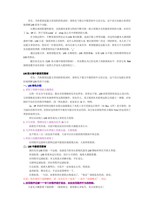
3.几乎所有设置都可以在界面上直接完成,方便快捷这个特点三言二语也说不清楚,大家可以在后面的使用指南中体会到。
目录PAD系统简介 (3)培训主题概述 (4)电脑基本知识 (5)打版放码系统 (7)生产实际流程 (9)纸样操作介绍 (10)排料操作介绍 (24)南京贝特CAD技术有限公司NANJING BETTER CAD TECHNOLOGIES CO., LTD.地址:南京市江宁区文靖路59号E-mail:316387972@PAD系统简介欢迎使用PAD计算机辅助服装设计系统。
PAD公司(PAD System Technologies)是世界最先进的服装CAD/CAM专业技术公司之一,其总部设在加拿大的蒙特利尔,在美国设有分部。
PAD在全球的54个国家和地区共有11,000多家用户。
本系统提供各种工具,用户可以在电脑上直接完成制版、打刀眼、打洞眼、贴边、作缝份、作省、省转移、剪切、拼接等传统的制版方法;并提供三种形象的放码方法,以应不同客户的需要;自动排料及人机交互式排料,灵活方便;独有的三维立体试衣,即时体现设计效果,同时检验版形线条,已减少生产失误。
系统的特点:1、系统操作灵活、方便、快速a、简单易学,操作方便;b、多视窗下编辑及修改;c、样片、设计图、排料图可在同一视窗或多个视窗间任意修改、复制/粘贴,以及多个模块间的复制/粘贴;d、排料图上可直接进行纸样编辑、修改。
2、苹果机和PC机下的WINXP的工作环境通用,操作界面亲切。
3、 PAD(派特)系统是个开放的系统a、能驱动三十多种绘图仪、二十多种数字化仪;b、图形及文本文件或其它著名服装CAD设计软件的数据库文件,如Gerber、Lectra等,都可在PAD(派特)系统环境下运行;4、独有的真三维立体试衣效果5、能适合每个人体需要,进行量身度做6、十四种语言版本可任意的选择、转换7、根据客户规模大小而定做的各种模块,不仅适应个人同时也适合大型企业培训主题概述派特系统的培训是使用户对技术的理解达到一个高的水平。
通过理论和实践的案例,用户将理解并能预估,在视窗上打板、放码及排料的不同步骤。
智威汤逊手册智威汤逊(WPP)是一家全球领先的综合性传媒和广告集团,提供广告、公关、市场营销等多种服务。
智威汤逊手册是为了帮助员工了解公司和业务,进一步提高工作效率和专业水平而编写的。
以下是智威汤逊手册的主要内容:1. 公司概况:手册开篇介绍智威汤逊的历史、发展和组织架构,让员工对公司有一个整体的了解。
2. 价值观和使命:明确智威汤逊的核心价值观和使命,例如客户第一、卓越创新等,以激发员工的归属感和团队合作精神。
3. 业务领域:介绍智威汤逊在广告、公关、市场研究和数字营销等领域的业务,以及在各个领域的领先地位和客户资源。
4. 组织架构:详细描述智威汤逊的各个业务单元和部门,以帮助员工了解公司的内部组织和工作流程,便于信息和资源的共享。
5. 工作职责和规范:列举不同职位的具体工作职责和要求,明确员工在各个岗位上的责任和任务,以保证工作效率和质量。
6. 员工发展计划:智威汤逊鼓励员工个人发展和职业成长,手册中会包含培训和发展计划,以及晋升路径和机会。
7. 薪酬和福利:介绍智威汤逊的薪酬体系和员工福利,包括基本工资、绩效奖金、健康保险、带薪休假等,让员工了解公司对待员工的权益和福利。
8. 企业文化和活动:介绍智威汤逊的企业文化和公益活动,例如团队建设、员工互动和社会责任等,让员工感受到公司的关怀和文化氛围。
9. 重要政策和流程:手册中会涵盖一些重要的公司政策和流程,例如行为准则、保密协议、项目管理流程等,以确保员工的工作符合公司的规定和要求。
10. 常见问题和答案:手册最后将列出一些常见问题和答案,供员工参考,以解答员工在工作中可能遇到的问题。
智威汤逊手册的目的在于帮助员工了解公司的组织结构、业务范围和工作方式,以便员工能更好地适应和融入公司的文化和团队中。
它是一份对员工负责的承诺,同时也是促进公司发展的关键工具。
智威汤逊手册是一份旨在帮助员工了解公司的综合性传媒和广告服务,并提高工作效率和专业水平的重要指南。
HikCentral ProfessionalQuick Start GuideContentsChapter 1 Guide Content (1)Chapter 2 Administrator Rights (2)Chapter 3 System Requirements (3)3.1 System Requirements for Servers (3)3.2 System Requirements for Control Client (3)Chapter 4 Installation (5)4.1 Install Module (5)4.1.1 Install Service Module in Custom Mode (6)4.1.2 Install Service Module in Typical Mode (7)4.2 Install Control Client (7)4.3 Service Manager (8)Chapter 5 Login (9)5.1 Recommended Running Environment (9)5.2 Login for First Time for admin User (9)Chapter 6 License Management (11)6.1 Activate License - Online (11)6.2 Update License - Online (13)Chapter 1 Guide ContentThis guide briefly explains how to install your HikCentral Professional as well as how to configure some of its basic features.To ensure the properness of usage and stability of the HikCentral Professional, please refer to the contents below and read the guide carefully before installation and operation.Chapter 2 Administrator RightsWhen you install and run the service modules, it is important that you have administrator rights on the PCs or servers that should run these components. Otherwise, you cannot install and configure the platform.Consult your IT system administrator if in doubt about your rights.If you access the platform via HikCentral Professional, you can log in to the operating system with the following default administrator user name and password at the first boot.●Default User Name: Administrator●Default Password: Abc12345It is recommended that you change the default administrator password immediately after entering the platform for data security.NoteWe highly recommend you to create a strong password of your own choosing (using a minimum of 8 characters, including at least three kinds of following categories: upper case letters, lower case letters, numbers, and special characters) in order to increase the security of your product. And we recommend you change your password regularly, especially in the high security system, changing the password monthly or weekly can better protect your product.Chapter 3 System Requirements3.1 System Requirements for ServersOperating SystemMicrosoft®Windows 11 (64-bit), Microsoft®Windows 10 (64-bit), Windows 8.1 (64-bit), Windows 7 SP1 (64-bit); Windows Server 2019 (64-bit), Windows Server 2016 (64-bit), Windows Server 2012 R2 (64-bit), Windows Server 2008 R2 SP1 (64-bit)NoteFor Windows 8.1 and Windows Server 2012 R2, make sure it is installed with the rollup(KB2919355) undated in April, 2014.CPUIntel®Core™ I3 and aboveMemory4 GB and aboveHDDSATA-II 7200 RPM Enterprise Class disk with 650 GB storage capacity. When running the SYS, there should be at least 1 GB free space.3.2 System Requirements for Control ClientOperating SystemMicrosoft®Windows 11 (64-bit), Microsoft®Windows 10 (64-bit), Windows 8.1 (64-bit), Windows 7 SP1 (64-bit); Windows Server 2019 (64-bit), Windows Server 2016 (64-bit), Windows Server 2012 R2 (64-bit), Windows Server 2008 R2 SP1 (64-bit), Mac OSNoteFor Windows 8.1 and Windows Server 2012 R2, make sure it is installed with the rollup(KB2919355) undated in April, 2014.CPUIntel®Core TM I5 and aboveMemory4 GB and aboveGraphics CardNVIDIA® Geforce GTX 970 and aboveHDDWhen running the Control Client, there should be at least 1 GB free space.Chapter 4 InstallationInstall the service modules on your servers or PCs to build your HikCentral Professional. Multiple installation packages are provided on the Hikvision's official website ( https:// ) and Partner Portal ( https:// ) for building your system.Basic Installation PackageOn the Hikvision's official website, this package is named as "HikCentral Professional.exe". It contains all the modules to build the system, including System Management Service, Streaming Service, Control Client, and Database Service.NoteThe System Management Service and Streaming Service cannot be installed on the same PC. Control Client Installation PackageOn the Hikvision's official website, four packages are provided to meet the requirement of different operating systems, including "HikCentral Professional Control Client x64.exe", "HikCentral Professional Control Client x86.exe", "HikCentral Professional Control Client x64.msi", and "HikCentral Professional Control Client x86.msi". This kind of package contains the Control Client module only.pStor Installation PackageOn the Hikvision's official website, this package is named as "pStor.exe". It contains a module to build the storage access service used for managing local HDDs and logical disks.SAC Installation PackageOn the Hikvision's official website, this package is named as "HikCentral Professional SAC Installer.exe". It contains a module to build the pStor cluster service for storage.Language Installation PackageOn the Hikvision's official website, this package is named as "HikCentral Professional LanguagePack.exe". It contains modules to display the system in different languages. OpenAPI Installation PackageOn the Partner Portal, this package is named as "HikCentralPro OpenAPI". It provides multiple APIs for third-party systems to fast integrate different applications .4.1 Install ModuleTwo installation methods are available for building the modules.Typical ModeInstall all the service modules (except the Streaming Service) and client.Custom ModeSelect the installation directory and modules to be installed as desired.4.1.1 Install Service Module in Custom ModeDuring installation in custom mode, you can select the installation directory and install the specified service modules as desired.Steps1.Double-click (HikCentral Professional) to enter the Welcome panel of the InstallShield Wizard.2.Click I agree to the terms in License Agreement and read the License Agreement.3.Select Custom Installation as setup type.4.Select the module(s) you want to install and click Next.Figure 4-1 Select Modules to InstallNoteThe System Management Service and Streaming Service cannot be installed on the same PC.In this way, you can install the service and client modules to different PCs or servers as desired.5.Optional:Select the hot spare mode if you select to install Video Surveillance Service in the previous step.-Select Normal if you do not need to build a hot spare system.-Select Mirror Hot Spare to build a mirror hot spare system. There are two HikCentral servers in the hot spare system: host server and spare server. When the host server works, the data in host server is copied to the spare server in real time. When the host server fails, the spare server switches into operation without interruption, thus increasing the reliability of thesystem.NoteFor building the hot spare system, contact our technical support engineer.6.Optional:Change the default directory as desired to install the program module(s) and the database.7.Click Custom Installation again to return to the Welcome panel.8.Click Install Now to begin the installation.A panel indicating progress of the installation will display.9.Click Finish to complete the installation.4.1.2 Install Service Module in Typical ModeYou can install all the service modules (except the Streaming Service) and client on one PC or server.Steps1.Double-click (HikCentral Professional) to enter the welcome panel of the InstallShield Wizard.2.Click I agree to the terms in License Agreement and read the License Agreement.3.Click Install Now to begin the installation.A panel indicating progress of the installation will display.4.Click Finish to complete the installation.4.2 Install Control ClientYou must install HikCentral Professional Control Client on your computer before you can access the system via Control Client. You can get the installation package from Hikvision's official site, or download from HikCentral Professional Web Client's Home page (64-bit).StepsNoteWe provide an installation package of Control Client in MSI format. For scenario with Active Directory Domain Services (AD DS), you can install/upgrade the Control Clients on the PCs in the AD domain in a batch by Windows® Group Policy. Click here to visit the official site of Microsoft®and you can view details and instructions about Windows® Group Policy.1.Double-click (HikCentral Professional_Client) to enter the welcome panel of the InstallShield Wizard.2.Optional:Select a proper directory on your computer to install the Control Client.3.Click Install Now to begin the installation.A panel indicating progress of the installation will display.4.Click Finish to complete the installation.4.3 Service ManagerAfter successfully installing the service module(s), you can run the Service Manager and perform related operations of service, such as starting, stopping, or restarting the service.Steps1.Right-click and select Run as Administrator to run the Service Manager.Figure 4-2 Service Manager Main PageNoteThe displayed items vary with the service modules you selected for installation.2.Optional: Perform the following operation(s) after starting the Service Manager.Stop AllClick Stop All to stop all the services.Restart AllClick Restart All to run all the services again.Stop SpecificService Select one service and click to stop the service.Edit Service Click the service name to edit the port of the service.NoteIf the port number of the service is occupied by other service, the port No.will be shown in red. You should change the port number to other value before the service can work properly.Open Service Location Select one service and click to go to the installation directory of the service.3.Optional: Check Auto-Launch to enable launching the Service Manager automatically after the PC started up.4.Click Dual-Server Deployment to deploy the database on another server.Chapter 5 LoginYou can access and configure the platform via web browser directly, without installing any client software on the your computer.NoteThe login session of the Web Client will expire and a prompt with countdown will appear after the configured time period in which there is no action. For setting the time period, refer to .5.1 Recommended Running EnvironmentThe following is recommended system requirement for running the Web Client.CPUIntel®Core™ I3 and aboveMemory4 GB and aboveWeb BrowserInternet Explorer®11 and above, Firefox®84 and above, Google Chrome®84 and above, Safari®11 and above,Microsoft®Edge 89 and above.NoteYou should run the web browser as the administrator.5.2 Login for First Time for admin UserBy default, the platform predefined the administrator user named admin. When you login via the Web Client for the first time, you are required to create a password for the admin user before you can properly configure and operate the system.Steps1.In the address bar of the web browser, enter the address of the PC running SYS service and press Enter key.ExampleIf the IP address of PC running SYS is 172.6.21.96, and you should enter http://172.6.21.96 or https://172.6.21.96 in the address bar.2.Enter the password and confirm password for the admin user in the pop-up Create Password window.The password strength of the device can be automatically checked. We highly recommend you change the password of your own choosing (using a minimum of 8 characters, including at least three kinds of following categories: upper case letters, lower case letters, numbers, and special characters) in order to increase the security of your product. And we recommend you change your password regularly, especially in the high security system, changing the password monthly or weekly can better protect your product.Proper configuration of all passwords and other security settings is the responsibility of the installer and/or end-user.3.Click OK.The Home page of Web Client will be displayed after you successfully creating the adminpassword.Chapter 6 License ManagementAfter installing HikCentral Professional, you have a temporary License for a specified number of cameras and limited functions. To ensure the proper use of HikCentral Professional, you can activate the SYS to access more functions and manage more devices. If you do not want to activate the SYS now, you can skip this chapter and activate the system later.Two types of License are available for HikCentral Professional:●Base: You need to purchase at least one basic License to activate the HikCentral Professional.●Expansion: If you want to increase the capability of your system (e.g., connect more cameras), you can purchase an expanded License to get additional features.Note●Only the admin user can perform the activation, update, and deactivation operation.●If you encounter any problems during activation, update, and deactivation, please send the server logs to our technical support engineers.6.1 Activate License - OnlineIf the SYS server to be activated can properly connect to the Internet, you can activate the SYS server in online mode.Steps1.Log in to HikCentral Professional via the Web Client.2.On the Home page, click Activate to open the Activate License panel.3.Click Online Activation to activate the License in online mode.Figure 6-1 Activate License in Online Mode4.Enter the activation code received when you purchased your License.Note●If you have purchased more than one Licenses, you can click and enter other activationcodes.●The activation code should contain 16 characters or 32 characters (except dashes).5.Check I accept the terms of the agreement to open the License Agreement panel and click OK.6.Optional:Select the machine environment type.Physical Machine (Default)A physical computer that contains hardware specifications and is used for running the SYS. Ifthe hardware changed, the License will be invalid, and the SYS may not run normally.AWS (Amazon®Web Services)A virtual machine that provides the cloud computing service for running the SYS.Azure (Microsoft®Azure)A virtual machine that provides the cloud computing service for running the SYS.NoteIf you select the machine environment type as the AWS or Azure, the pStor server, Streaming Server, and other external servers can not access the platform. And the Rose hot spare system is also not supported.7.Optional:Check the Hot Spare, select type, and enter the IP address if you want to build a hot spare system.Note●You must select Hot Spare mode when you install the system.●For how to build the hot spare system, please contact our technical support engineers.8.Click Activate.The email settings pane will appear after activating the License.9.Enter an email address for the admin user.NoteThis email is used to receive the License activation code when the admin user forgets the password for logging in to the platform and the activation code at the same time.10.Set the email server parameters.11.Click OK to save the email settings.6.2 Update License - OnlineAs your project grows, you may need to increase the connectable number of resources (e.g., cameras) for your HikCentral Professional. If the SYS to be updated can properly connect to the Internet, you can update the License in online mode.Before You StartContact your dealer or our sales team to purchase a License for additional featuresSteps1.Log in to HikCentral Professional via the Web Client.2.In the top right corner of Home page, select Maintenance and Management→ Update License → Online Update to open the Online Update panel.3.Enter the activation code.Note●If you have purchased more than one Licenses, you can click and enter other activationcodes.●Up to 110 Licenses are allowed in one system.4.Check I accept the terms of the agreement to open the License Agreement panel and click OK.5.Click Update.。
Blue Coat ProxySG First Steps Solution for Exception PagesSGOS6.7Legal NoticeBroadcom,the pulse logo,Connecting everything,and Symantec are among the trademarks of Broadcom.The term“Broadcom”refers to Broadcom Inc.and/or its subsidiaries.Copyright©2021Broadcom.All Rights Reserved.The term“Broadcom”refers to Broadcom Inc.and/or its subsidiaries.For more information,please visit .Broadcom reserves the right to make changes without further notice to any products or data herein to improve reliability,function, or rmation furnished by Broadcom is believed to be accurate and reliable.However,Broadcom does not assume any liability arising out of the application or use of this information,nor the application or use of any product or circuit described herein, neither does it convey any license under its patent rights nor the rights of others.Friday,May28,2021Blue Coat ProxySG First StepsContentsSolution:Create Custom Exception Pages4 Steps4 Set Services to Intercept4 Design a Custom Exception Page4 Install a Custom Exception Page7 Create Policy for a Custom Exception Page9 Test a Custom Exception Page10Exception Page Troubleshooting11 Why are HTML tags displaying in my browser?11 How can I view the exception page I created?11 Why doesn't the content of my exception page display?12 Why can't I delete my custom exceptions page?123Creating Custom Exception Pages Solution:Create Custom Exception PagesAn exception page is an HTML page that appears in a user's web browser after the person has tried to access a website the company has blocked access.For example,if the company has a policy that blocks the Shopping URL category and a user attempts to go to ,an exception page displays instead of the Amazon website.The ProxySG offers built-in exception pages and allows you to create custom exception pages.The steps below are the tasks you need to perform in order to create custom exception pages.Steps1."Design a Custom Exception Page"below.2."Install a Custom Exception Page"on page 7.3."Create Policy for a Custom Exception Page"on page 9.4."Test a Custom Exception Page"on page 10.Set Services to InterceptIn transparent ProxySG deployments,Internet applications aren't aware that the proxy is in the network,so the ProxySG has to monitor the ports used for their traffic.The most common ports are80(HTTP),443(HTTPS), and1935(RTMP).For explicit proxy deployments,client browsers direct all traffic to the appliance on the same port,(typically80or8080).When explicit traffic is intercepted,the appliance uses an advanced protocol detection method to identify the type of traffic(HTTP, HTTPS,RTMP,and so on)and handles it according to the standards for that traffic.Open the Proxy Services page(Configuration>Services>Proxy Services)and set the desired services to Intercept. Design a Custom Exception PageException pages are rendered in HTML.To design a custom exception page,you need to create an HTML page to display your customized exception message.The HTML page you design displays when users try to access content for which a blocking policy has been created.This topic discusses the process of designing your custom exception page using HTML code.1.Copy the following HTML code.<!DOCTYPE html><html><head>4Blue Coat ProxySG First Steps<title>Denied Access Policy</title><meta name="author"content="Your Company Name Here"><meta name="description"content="Denied Access Policy"><meta name="category"content="$(exception.category)"></head><body><center><img src="/images/NameOfImage.jpg"/><br><p><font face="Arial,Helvetica,sans-serif"size="4"color="Red"><b>You are about to access the internet from:Your Company Network</font><br><font face="Arial,Helvetica,sans-serif"size="4"color="Red">INTERNET USAGE IS MONITORED AND LOGGED.</font><br><font face="Arial,Helvetica,sans-serif"size="3"color="Red"><b>Your IP address:123.45.67.89<!--$(client.address)--><br>Your username:Jane Smith<!--$()--></b></font><br><font face="Arial,Helvetica,sans-serif"size="4"color="red">YOU HAVE BEEN DENIED ACCESS TO THIS SITE.PLEASE READ OUR SECURITY POLICY AT:/up.html<front><br> <font face="Arial,Helvetica,sans-serif"size="4"color="red">This has been reported by: Your Proxy Name<!--$()--><font><br>For any comments email<A href='mailto:***********************?subject=Barred web page<!--$(url)-->,IP address:<!--$(client.address)-->,User ID:<!--$(user)-->'>Customer ServiceCenter</a></font></a></font></p></center></body></html>2.Paste the copied HTML code into an HTML or text editor.Each tag is designed to hold a particular type of text and It's important that you use each tag according to that purpose.Below is a close up of each tag that needs to be modified to fit your exception page needs.a.Edit the title of the exception page by removing the text in between the opening and closing title tags,andreplacing that text with the name of the exception page you are creating.<title>Exception Page Title</title>.b.Edit the meta data tags to represent your company name,and the name of the exception.<meta name="author"content="Your Company Name Here"><meta name="description"content="Denied Access Policy">5Creating Custom Exception Pages c.Edit the image tag to include your company logo.<img src="/images/NameOfImage.jpg"/>.d.Edit the text between the opening and closing<font>tags to create your desired exception message.Thefont tags below display the body of your exception message.<font face="Arial,Helvetica,sans-serif"size="4"color="Red"><b>You are about to access the Internet from the Your Company Network</font><br><font face="Arial,Helvetica,sans-serif"size="4"color="Red">INTERNET USAGE IS MONITORED AND LOGGED.</font><br><font face="Arial,Helvetica,sans-serif"size="3"color="Red"><b>Your IPaddress:123.45.67.89<!--$(client.address)--><br>Your username:<!--$()--></b></font><br><font face="Arial,Helvetica,sans-serif"size="4"color="red">YOU HAVE BEEN DENIED ACCESS TO THIS SITE.PLEASE READ OUR SECURITY POLICY AT/up.html<front><br><font face="Arial,Helvetica,sans-serif"size="4"color="red">This has been reported by<!--$()-><font><br>For any comments email<A href='mailto:***********************?subject=Barred web page<!--$(url)-->,IP address:<!--$(client.address)-->,User ID:<!--$(user)-->'> Customer Service Center</a></font></a></font>e.Edit the font tag itself to change the font type,size and color.For example,to change the size of the fontto7,you need to change the attribute,from size="3"to size="7".Each attribute’s value must besurrounded in quotes otherwise the HTML does not render as desired.<font face="Arial,Helvetica,sans-serif"size="3"color="Red"><b>Your IP address:6Blue Coat ProxySG First Steps$(client.address)<br>Your username:$()</b></font><br>3.Save the file with the.html file extension.Substitution variables are predefined variables that can be included in your exception page.These variables,when referenced in your HTML code,display the values of the variables when the exception page is displayed to the user.The most commonly used substitution variables are listed below.Variable Description$(exception.category)The category of the requested URL$(user)The name of the requester$(url.host)The requested URL's host name portion$()The name of the ProxySG$(client.address)The IP address of the clientA full list of variables can be found in the ProxySG Log Fields and Substitutions guide.Install a Custom Exception PageBefore you begin this step,be sure that you have completed the steps in the topic"Design a Custom Exception Page"on page 4.Use the command line interface to install the custom exceptions page you created.e a remote login utility(such as Putty)to access the command line interface.2.Enter the following CLI commands:SG#enableEnable Password:SG#conf tSG#(config)exceptionsSG#(config exceptions)create my_exceptionokSG#(config exceptions)edit my_exceptionSG#(config exceptions user-defined.my_exception)inline format EOF3.Copy the code from your HTML file and paste that code into the command line.4.After you have pasted in the HTML code,type EOF to signal the end of your code.ok7Creating Custom Exception PagesOnce you have entered your CLI commands and HTML code in to the CLI,your screen should be similar to the following example.5.Assign an HTTP response status code to your custom exception page by entering the following command:SG#(config exceptions user-defined.my_exception)http-code<code#>okwhere<code#>is one of the following HTTP status codes:302,307,403.(403is probably the most common when creating policy for blocked URL categories.)Status Code Description302The requested URL was temporarily changed but the same URL should be used in the future.307The URL was temporarily moved.The new URL should be given.403Access forbidden.8Blue Coat ProxySG First StepsCreate Policy for a Custom Exception PageTo reference the custom exceptions page you have created,you need to create policy.By creating policy,you instruct the ProxySG how to handle the exceptions being processed.1.Log in to the ProxySG Management Console.2.Open the Visual Policy Manager.a.Select Configuration>Policy>Visual Policy Manager.b.Click Launch.The VPM opens in a new window.3.Select Policy>Add Web Access Layer.4.In the Add New Layer pop-up dialog,enter a name for the Web Access layer and click OK.5.To define the action that returns your custom exception,right-click the Action column and select Set.The Set ActionObject dialog opens.6.Select New>Return Exception from the Set Action Object dialog.The Add Return Exception Object dialog opens.7.Select User-defined exception in the Add Return Exception Object dialog.9Creating Custom Exception Pages8.Select the custom exception you created from the User-defined exception drop-down list.9.Click OK and click OK again.10.Install the policy.11.Close the Visual Policy Manager.Test a Custom Exception PageTo test your custom exception page,go to a URL denied by your policy.For example,if the Shopping category is blocked,go to .You should see the custom exceptions page you created.10Blue Coat ProxySG First StepsException Page TroubleshootingWhy are HTML tags displaying in my browser?11 How can I view the exception page I created?11 Why doesn't the content of my exception page display?12 Why can't I delete my custom exceptions page?12Why are HTML tags displaying in my browser?Problem:When I click"View Sample HTML,"from the Management Console,my content displays but fragments of HTML tags mistakenly display as well.Resolution:When you code HTML,all tags and characters must have opening and closing characters to match.For example, every<opening tag>must have a matching</closing tag>.Similarly,all""and<>need to be properly opened and closed.If you do not do this,HTML renders improperly in various ways.Colors may not display correctly,a blank page may display or images may appear broken.1.In a text or HTML editor,open the HTML file containing your exception page code.Study the code to make sure allopening tags have matching closing tags.Look for other errors(such as typing mistakes)in your tags.correct any errors you find.2.Log in to your CLI console using a remote log-in utility.3.To edit the exception page,enter the following commands.SG#configSG#exceptionsSG#edit name_of_exceptionSG#inline EOF4.Copy the HTML code from the file you edited in step1above.5.Paste the HTML code into your CLI console.6.Type EOF and press Enter.How can I view the exception page I created?Problem:I would like to see a preview my custom exception page.11Creating Custom Exception Pages Resolution:1.In the Management Console,select Configuration>Policy>Exceptions.2.Select View File>Exception Configuration>View.3.Choose the exception you would like to view from the User-Defined list.Click View Sample HTML.The customexception page opens in a new window.Why doesn't the content of my exception page display?Problem:When I view my HTML output in the Management Console viewer,I am only able to see the name of the exception page I created.The image below is how the browser displays my custom exception page.Resolution:When you name your custom exception page,it is not necessary to precede the name with"user-defined."If you have mistakenly preceded the name of your exception with"user-defined,"you need to delete it so that you can recreate the exception.You can do that by following the procedures listed in the"Why can't I delete my custom exceptions page?"below topic.After deleting the misnamed exception,you can create a new custom exception page,with the correct name,by following the procedures in the"Solution:Create Custom Exception Pages"on page 4Why can't I delete my custom exceptions page?Problem:I cannot delete the custom exception page I created.Resolution:Custom exception pages that are referenced by policy cannot be deleted.In order to delete your custom exception page,you must first delete the policy that references the custom exception you wish to delete.Once you have deleted the policy,you can delete the custom exception.1.Log in to the Management Console.2.Select Configuration>Policy>Visual Policy Manager>Launch.3.In the VPM,right-click the tab of the policy layer you wish to delete.12Blue Coat ProxySG First Steps4.Click Delete Layer or Rule.5.Click Yes to confirm the deletion.6.Close the VPM.Once the above instructions are complete,you can delete the custom exception.1.Log in to your CLI console using a remote log-in utility.2.Enter the following CLI commands.SG#configSG#exceptionsSG#edit name_exceptionSG#delete name_exceptionok13。
首先,当你看到这篇文章而跃跃欲试时,请你先下载文中提供的中文语言包,这个语言包能让你更好地理解LNS的各个功能。
长期以来因机器性能差,且机器有重要文档而不断寻找一款占资源少且性能优异的防火墙,在经历了ZA、OP后,终于发现Look’n’stop是心目中理想的防火墙。
在寻找过程中,不断发现有网友认为LNS难以配置、造成不能上网等问题,对这些问题本人感到困惑和不解:LNS只是一款简单的工具软件,是什么原因使大家难以使用呢?经过一周的研究,本人有了写这篇文章的冲动,恰好应一位朋友所托,故写出来与大家共享。
希望能通过这篇文章,使英文不太好的网友也能很快掌握并熟悉使用这个款难得的墙。
^_^通过这篇文章,我希望能改变:LNS太难使用、LNS规则难编、安装LNS后不能上网的那些网友对LNS的看法。
题目估且定为《LNS防火墙中级使用指南》,其实偶认为已经达到了高级指南水平,但其它如Raw规则设置并没有讲到(虽然几乎没有人能用到它)。
LNS防火墙中级使用指南首先,当你看到这篇文章而跃跃欲试时,请你先下载文中提供的中文语言包,这个语言包能让你更好地理解LNS的各个功能。
一、LNS特色介绍1.采用了理想中的防火墙理论记得一位安全专家说过:最安全的策略的先否定所有,再肯定个别。
LNS的原型恰恰是这么设计的,它的策略是先禁止所有本地和所有远程的操作,再允许之,真正做到在本机和远程之间建立一堵墙,在初始时不信任任何程序和操作。
因一网友批评,此处省去45字,呵呵。
ZA、OP的组件控制功能在安装完成就假定了本机上非可直接运行程序(如DLL 文件)是可靠的,故当成信任程序对待,但恰好这些程序中就有可能含有非法代码。
其它知名的软件防火墙如Tiny的也采用了类似的处理方法。
所以从结构上LNS就有成为王者的先天优势。
2.小巧灵珑,物理内存+虚拟内存共4M左右此特色不用多说,目前可能还没有任何防火墙能及其左右。
3.几乎所有设置都可以在界面上直接完成,方便快捷这个特点三言二语也说不清楚,大家可以在后面的使用指南中体会到。
4.所有已设置的规则直观明了应用程序过滤和互联网过滤中能很好地展现出来,大家即将看到。
二、LNS中级使用指南我们先对LNS的做一个远观,也就是当你双击系统托盘里LNS图标时所打开的主界面。
欢迎标签:LNS的基本运行状态,没什么可讲的,地球人都能看懂。
应用程序过滤标签:本文的重点讲解对象,不忙说它。
互联网过滤标签:同应用程序过滤标签。
日志标签:地球人都明白,可是不一定知道怎么用,得说说。
选项标签:顾名思义,不过还是得唠叨一下。
注册标签:一句话,如果你用注册机注册成功了,“验证”按钮是灰色的,恭喜。
注意:你在使用下述图解时,请一定先打开“选项”—>选中“高级模式”,切记。
1.应用程序过滤----专门对程序进行设定,决定应用程序行为的控制。
大家先大概看看下面的图一(做的很丑,看到那么多标号,差点没晕过去)先看看红色编号1区,这个区显示是正连接在网络上或者曾经连接过网络目前还没有关闭的软件清单。
重点是看绝色编号2区,这个区才是重点,有N多的门道在里面。
这个区猛一看是已允许的相信的程序,仔细看看,偶已经列出了11种属性,当然也是可能的全部属性了。
现在按此区的“列”来开讲^_^,之前必需选中黑色编号12“应用程序过滤已启用”,否则所做的任何设置都不起作用,嘿嘿。
第一列只有此二种属性,简而言之就是启用或者禁用该规则,单击实现二种属性之间的切换。
见黑色编号1,黑色编号2。
黑色编号1,是指启用为它所在行的那个程序制定的规则,也就是说让该程序按既定的规则运行,此所谓的应用程序过滤。
如果你不想为这个程序设置的规则起作用的话,那么点击一下,就会变成黑色编号2所指的样子。
第二列有三种属性,分别是允许(黑色编号5)、禁止(黑色编号4)、自定义(黑色编号3)。
单击则在允许与禁止之间切换,如果有自定义属性,则在三者之间进行切换。
黑色编号3:黄色圆饼标志。
当你为此程序制定了特殊规则,如指定程序只能连接远程的哪些端口、或者不允许连接哪些端口;允许连接哪些地址、禁止连接哪些地址时,则出现黄色的圆。
(功能强大,设置之灵活让人唏嘘。
)具体看看如下:双击某个程序(当然也可以通过点击点击黑色编号12来实现),就会出现如图二所示的“选择端口和IP地址”窗口,此时你可以设置具体的内容了。
比如,偶的TW,偶只允许它连接远程的80端口,不允许连接其它端口,那么就按上面的设置;此时对IP地址没有限制。
如果你想让他只连接远程的某个IP地址,那么就在IP地址栏输入。
当然没有人会这么对待浏览器。
这个自定义功能不会只是如此简单吧?当然不是,其实重要的不是允许去什么地方,而是禁止它去什么去什么地方。
比如,你的CuteFTP一启动就想去它的主站验证一下它的合法性,那么你就可以在这里设置一下了,而又不影响其它程序(如IE)访问CuteFTP的主站(目前偶还没有发现哪个防火墙能这样设置的,嘿嘿,如果有恕偶无知)。
说了半天,允许和禁止在这里是看不出区别的,该怎么办?其它很简单,允许访问的端口或者IP,则直接输入在上面就行。
如果你要禁止某个端口或者地址,呵呵,只要在端口前面加上一个感叹号“!”就行了,是不是真的简单?对了,如果是多个IP或者端口,不要忘记在它们之间加上一个半角的分号“;”哦。
黑色编号4:红色禁止标志。
此标志表示禁止该程序连接网络。
黑色编号5:绿色允许标志。
此标志表示允许该程序连接网络。
现在来看第三列,此列只有二种属性,单击则实现二种属性之间的切换。
见黑色编号7、黑色编号9。
这一列是强大功能的一个体现,作用是允许或者禁止此程序调用另一个程序并且使用被调用的这个程序连接网络,也就是说:A程序启动了B程序,B程序有连网企图,此属性就是对这种情况进行控制的。
必须打开“高级选项”中的“高级模式”才会出现此列。
黑色编号7:双箭头标志。
当为此标志时则意味着允许当前程序去调用另外一个要使其连接网络的程序。
如果发生这种情况,则出现提示窗。
黑色编号9:红色禁止标志。
当为此标志时不允许当前程序去调用另外一个要使其连接网络的程序,当然如果被调用的程序没有连接网络的企图,则防火墙是不出现提示的。
第四列,此列有三种属性,其中二种属性与第一列的属性配合才能看到效果。
黑色编号6、黑色编号10、黑色编号11。
黑色编号11:如果是这个标志,则什么也不发生。
相当于此属性被禁用。
黑色编号10:单感叹号标志。
此标志表示在日志中记录该应用程序的连网“企图”,此时要与第一列配合使用,第一列的属性必须是禁止标志才起作用。
这个功能的好处太多了,比如:一个被你禁止了的程序,可能也已经关闭了,但频频试图连网,估计它也不是什么好东西,木马常常这么干!黑色编号6:双感叹号标志。
此标志表示无论该程序是禁止还是允许连网,都在日志中记录。
好了,应用程序过滤篇到此完毕。
可以看出,LNS对程序的控制非常灵活且强大,10个属性有36种不同组合。
仅一个页面可以实现允许禁止、记录与否、单程序访问控制、进程调用四种功能的控制。
2.互联网过滤----专门对防火墙规则进行设定,也有少量设定涉及到程序。
决定网络连接及数据包行为的控制。
图三是互联网过滤,继续按“列”进行讲解。
此页面部分功能与“选项”时的“消息框”、“声音”、“日志”配合使用。
第一列,有三种属性。
自定义的启动该规则属性、默认的启用该规则属性、不启用该规则属性,分别对应黑色编号3、黑色编号1和黑色编号2。
三种属性之间点击进行切换,但如果没有进行自定义,则只在二种属性间切换。
黑色编号1:绿色带勾标志。
此标志表示启用该规则,且该规则没有进行特别的自定义。
黑色编号2:灰色小圆点标志。
此标示表示不使用该规则,也就是说防火墙对网络连接请进行检查时不与该规则进行匹配操作。
相当于这条规则只是临时放在这里,并没有什么作用。
黑色编号3:暗红色带勾标志。
此标志表明这条规则只对特定的程序起作用,当此特定的程序启动后,此标志则变为绝色带勾标志,表示规则启用了,否则为暗红色带勾标志,表示这规则暂时未被启用。
这种设置方式似乎也没有在其它防火墙中见到,极其特别,也是LNS灵活的一个体现。
它的好象是什么呢?显示易见,当该特定程序没有启动时,就相当于少了一条规则,少一条规则多一分安全是主要的;其次可以加快对规则匹配操作的时间。
设置特定程序的方法为双击当前规则,出现一个设置窗如图四所示。
双击一条规则后会出现如红色编号1的窗口,点击些窗口上的“应用程序…”按钮,出现如红色编号2所示的窗口,将此窗口中右侧的程序双击添加到左侧,然后一路确定就可以了。
图示是偶为BT添加的自定义规则,只有当BT 启动后它才启用,平时这条规则相当于不存在,呵呵,否则会浪费偶的资源的。
第二列,有二种属性。
分别是禁止与允许,对应于黑色编号4。
此列主要用途是,允许执行与此规则匹配的连接请求,还是禁止与此规则匹配的连接请求。
黑色编号4:红色禁止标志。
此标志表示,当某个连接请求或者操作与此规则匹配时,则禁止该连接请求或者操作。
如果是灰色圆点标志,则表示此允许此连接请求或者操作。
此属性的好处是,可以用来限制某些特定的操作而又不产生全局影响,而当你需要时又可以打开这一特定规则。
第三列,二种属性。
记录或者不记录与该规则匹配的操作信息。
黑色编号6:单感叹号标志。
表示当某个连网请求或者操作与此规则匹配时,则记录些操作的信息,这些信息一定会在日志标签的窗口里显示出来。
如果你启用了“选项”标签中的日志文件功能,则这些信息保存在日志文件中,如果没有启用日志文件功能,则不保存。
另一灰色圆点标志表示不记录也不保存这些信息。
本人建议把LNS的记录功能打开,这样一旦某些软件不能正常上网时,可以在日志中发现并生成规则(后面讲到如何用日志生成适用规则)。
第四列,二种属性。
分别对应黑色编号7、黑色编号8。
功能比较简单,但却非常的有用啊。
黑色编号7:黄色下箭头标志。
些标志表示,如果某个操作与此规则匹配时,则直接进行相应的操作(即第一列、第二列、第三列所定义的属性及具体规则内容进行操作),不再继续匹配后续的其它规则,因为LNS匹配规则的顺序是自上而下的(故大家最好不要调整那些LNS默认生成的规则的上下顺序,否则可能什么程序也上不了网)。
这种属性产生的操作带来的好处是:不用将所有规则匹配一遍,极大地减少了LNS规则匹配操作所用的时间;其次如果你添加了一条过于宽泛自己不知道有没有漏洞的规则,那么你可以关闭此属性,则当有某个操作与此规则匹配后,后续规则继续对其进行检测,以发现问题。
黑色编号8:灰色圆点标志。
此标志表示匹配完此规则后,再继续匹配后续规则。
第五列,三种属性。
对应于黑色编号9、黑色编号10。
作用是当有某操作与此规则匹配时,以什么方式来报警。