US100使用说明
- 格式:pdf
- 大小:209.66 KB
- 文档页数:4
+GF+ SIGNET 8850-1 电导/电阻率表说明书Signet公司的电导/电阻率表在使用前必须被设置和校正(注意:这些已经在本公司被完成)。
阅读仪表随带说明书可以获得更多的安装细节。
一、菜单功能VIEW(观察浏览)菜单:在标准操作期间显示。
●按“▲”或“▼”按钮观察过程参数。
通过按钮的操作,将依次显示:被测介质流量及温度的过程数据、当前输出的电流信号值、最后修改参数的时间。
●10分钟内不按任何按钮,显示界面将回到“VIEW”菜单。
CALIBRATE(校准)菜单:包含了显示设置和输出参数设置功能。
进入此菜单设有密码功能,防止未经授权的私自篡改。
进入CALIBRATE 菜单步骤:●按“ENTER”按钮2秒将显示:CALIBRATE:――――Enter Key Code●依次按“▲”、“▲”、“▲”、“▼”按钮将显示:CALIBRATE:××××Enter Key CodeOPTIONS 菜单:包含了为其它次要的显示或输出调整的设置功能和显示功能。
进入“OPTION”菜单步骤:●按“ENTER”按钮5秒将显示:OPTIONS:――――Enter Key Code●依次按“▲”、“▲”、“▲”、“▼”按钮将显示:OPTIONS:××××Enter Key Code二、菜单提示●当“>”符号显示时,“►”键功能可用来向右卷动,从顶行移动到底行,并且允许进行编辑。
●进入“CALIBRATE”或“OPTIONS”菜单,电导/电阻率变送器将继续测量和1控制输出。
当“►”键被按下时,输入值被抑制在最后测得的过程值。
当传感器没有被连接时,流量变送器将显示“CHECK SENSOR(检查传感器)”。
三、举例说明:(改变修改日期)为了改变日期,第一步进入“CALIBRATE”菜单(按“ENTER”按钮2秒;依次按“▲”、“▲”、“▲”、“▼”按钮),一旦进入“CALIBRATE”菜单,按“▲”按钮1次或依次按“▼”按钮,直至屏幕显示“Last Call:”。
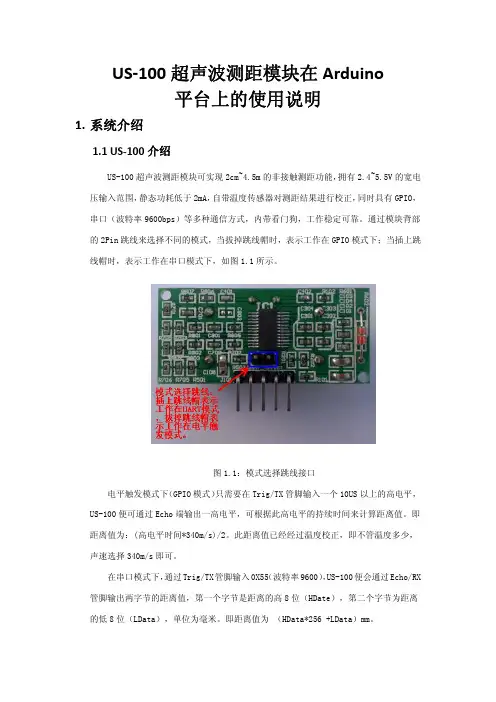
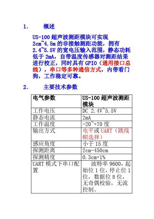
1.概述US-100超声波测距模块可实现2cm~4.5m的非接触测距功能,拥有2.4~5.5V的宽电压输入范围,静态功耗低于2mA,自带温度传感器对测距结果进行校正,同时具有GPIO(通用接口总线),串口等多种通信方式,内带看门狗,工作稳定可靠。
2.主要技术参数3.本模块实物图及尺寸本模块如图3.1和图3.2所示:图3.1:US-100正面图本模块的尺寸:45mm*20mm*1.6mm。
板上有两个半径为1mm的机械孔,如图3.3所示:图3.3:US-100尺寸图4.接口说明本模块共有两个接口,即模式选择跳线和5 Pin接口。
模式选择跳线接口如图4.1所示。
模式选择跳线的间距为2.54mm,当插上跳线帽时为UART(串口)模式,拔掉时为电平触发模式。
图4.1:模式选择跳线接口5 Pin接口为2.54mm间距的弯排针,如图4.2所示:图4.2:5 Pin接口从左到右依次编号1,2,3,4,5。
它们的定义如下:1号Pin:接VCC电源(供电范围2.4V~5.5V)。
2号Pin:当为UART模式时,接外部电路UART的TX端;当为电平触发模式时,接外部电路的Trig端。
3号Pin:当为UART模式时,接外部电路UART的RX端;当为电平触发模式时,接外部电路的Echo端。
4号Pin:接外部电路的地。
5号Pin:接外部电路的地。
5.电平触发测距工作原理在模块上电前,首先去掉模式选择跳线上的跳线帽,使模块处于电平触发模式。
电平触发测距的时序如图5.1所示:图5.1:US-100测距时序图图5.1表明:只需要在Trig/TX管脚输入一个10US以上的高电平,系统便可发出8个40KHZ的超声波脉冲,然后检测回波信号。
当检测到回波信号后,模块还要进行温度值的测量,然后根据当前温度对测距结果进行校正,将校正后的结果通过Echo/RX管脚输出。
在此模式下,模块将距离值转化为340m/s时的时间值的2倍,通过Echo端输出一高电平,可根据此高电平的持续时间来计算距离值。
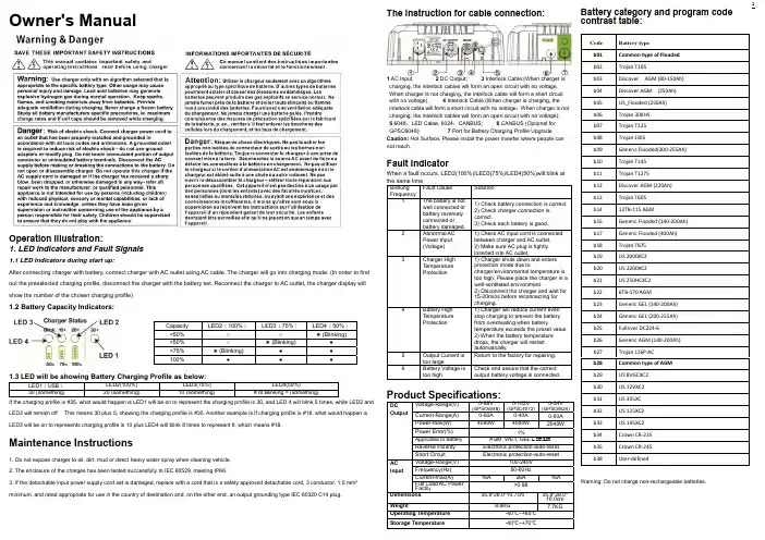
1Owner's ManualOperation illustration:1. LED Indicators and Fault Signals1.1 LED Indicators during start up:After connecting charger with battery, connect charger with AC outlet using AC cable. The charger will go into charging mode. (In order to find out the preselected charging profile, disconnect the charger with the battery set. Reconnect the charger to AC outlet, the charger display will show the number of the chosen charging profile)1.2 Battery Capacity Indicators:1.3 LED will be showing Battery Charging Profile as below:LED1(USB ) LED2(100%) LED3(75%) LED4(50%) 30 (something)20 (something) 10 (something) # of Blinking = (something)If the charging profile is #35, what would happen is LED1 will be on to represent the charging profile is 30, and LED 4 will blink 5 times, while LED2 and LED3 will remain off. This means 30 plus 5, showing the charging profile is #35. Another example is if charging profile is #18, what would happen is LED3 will be on to represents charging profile is 10 plus LED4 will blink 8 times to represent 8, which means #18.Maintenance Instructions1. Do not expose charger to oil, dirt, mud or direct heavy water spray when cleaning vehicle.2. The enclosure of the charges has been tested successfully to IEC 60529, meeting IP66.3. If the detachable input power supply cord set is damaged, replace with a cord that is a safety approved detachable cord, 3 conductor, 1.5 mm² minimum, and rated appropriate for use in the country of destination and, on the other end, an output grounding type IEC 60320 C14 plug.The instruction for cable connection:1 AC Input;2 DC Output;3 Interlock Cable:(When charger ischarging, the interlock cables will form an open circuit with no voltage.When charger is not charging, the interlock cable will form a short circuit with no voltage); 4 Interlock Cable:(When charger is charging, the interlock cable will form a short circuit with no voltage ;When charger is notcharging, the interlock cables will form an open circuit with no voltage); 5 6048:LED Cable, 6024:CANBUS; 6 CANBUS (Optional for GPSC6048); 7 Port for Battery Charging Profile UpgradeCaution: Hot Surface. Please install the power inverter where people cannot reach .Fault IndicatorWhen a fault occurs, LED2(100%)/LED3(75%)/LED4(50%)will blink atthe same time.Blinking FrequencyFault Cause Solution 1 The battery is notwell connected orbattery reverselyconnected orbattery damaged.1) Check battery connection is correct.2) Check charger connection iscorrect.3) Check each battery is good..2 Abnormal AC Power Input (Voltage) 1) Check AC input cord is connectedbetween chargerand AC outlet. 2) Make sure AC plug is tightlyinserted into AC outlet.3 Charger High TemperatureProtection1) Charger shuts down and entersprotection mode due to charger/environmental temperature is too high. Please place the charger in a well-ventilated environment.2) Disconnect the charger and wait for 15-20mins before reconnecting for charging.4 Battery High Temperature Protection 1) Charger will reduce current evenstop charging to prevent the battery from overheating when batterytemperature exceeds the preset value. 2) When the battery temperature drops, the charger will restart automatically.5 Output Current is too largeReturn to the factory for repairing.6 Battery Voltage is too high Check and assure that the correctoutput battery voltage is connected.Product Specifications:DCOutputVoltage-Range(V)0-68V(GPSC6048) 0-102V (GPSC4072) 0-34V(GPSC6024)Current-Range(A) 0-60A 0-40A 0-60APower-max(W) 4080W 4080W 2040W Power Error(%)1%Applicable to BatteryAGM, WET, GEL Lithium Reverse Polarity Electronic protection-auto-reset Short CircuitElectronic protection-auto-resetACInputVoltage-Range(V) 100-240V Frequency(Hz) 50-60Hz Current-max(A) 16A 26A 16AFull Load AC Power Factor>0.98Dimensions 35.8*28.0*10.7cm35.8*28.0* 10.0cmWeight 8.6KG 7.7KG Operating Temperature -40℃~+65℃Storage Temperature -40℃~+70℃Battery category and program code contrast table:Code Battery type b01Common type of Floodedb02 Trojan T105b03 Discover AGM (80-150Ah) b04 Discover AGM (250Ah)b05 US_Flooded (250Ah) b06 Trojan 30XHS b07 Trojan T125 b08 Trojan J305 b09 Generic Flooded(200-255Ah) b10 Trojan T145 b11 Trojan T1275 b12 Discover AGM (220Ah) b13 Trojan T605 b14 12TB-115 AGM b15 Generic Flooded (140-200Ah) b17Generic Flooded (400Ah)b18 Trojan T875 b19 US 2000XC2 b20 US 2200XC2 b21 US 250HCXC2 b22 6TB-170 AGMb23 Generic GEL (140-200Ah) b24 Generic GEL (200-255Ah) b25 Fullriver DC224-6 b26 Generic AGM (140-200Ah) b27 Trojan L16P-AC b28Common type of AGMb29 US 8VGCXC2 b30 US 12VXC2b31 US 305XC b32 US 125XC2 b33 US 145XC2 b34 Crown CR-235 b35 Crown CR-245 b38 User-definedWarning: Do not charge non-rechargeable batteries.Capacity LED2(100%) LED3(75%) LED4(50%) <50%○ ○★ (Blinking)>50% ○★ (Blinking)● >75% ★ (Blinking)● ● 100%●●●2使用说明书一、警告信息请在使用本产品前详细阅读使用说明书,理解这些安全指导,并保存好此说明书以方便取阅。
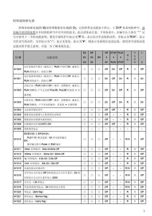
特殊辅助继电器特殊补助继电器(特M)及特殊数据寄存器(特D),它的种类及功能如下所示。
于DVP各系列机种中,部份编号相同的装置在不同的机种当中有不同的意义,此点请务必注意。
下列各表中,在编号右上角有”*” 记号可参考下一节的功能说明,像其中属性栏中标示为”R”者,表示仅可作读取的动作,若标示为”R/W”,表示可作读写的动作。
另若标示为”-”,表示无变化。
标示为”#”,则表示为系统信息设定值,使用者可读取该设定值对照手册之说明,可进一步了解系统信息。
特M 功能说明ESEXSSEPSASXEHOffOnSTOPRUNRUNSTOP属性停电保持出厂值M1000*运行监视常开接点(a接点)。
RUN中常时On,a接点。
RUN的状态下,此接点On○○○ Off On Off R 否 OffM1001*运行监视常闭接点(b接点)。
RUN中常时Off,b接点。
RUN的状态下,此接点Off○○○ On Off On R 否 OnM1002*启始正向(RUN的瞬间’On’)脉冲。
初期脉冲,a接点。
RUN的瞬间,产生正向的PULSE,PULSE的宽度 =扫描周期○○○ Off On Off R 否 OffM1003*启始负向(RUN的瞬间’Off’)脉冲。
初期脉冲,a接点。
RUN的瞬间,产生负向的脉冲,其宽度 =扫描周期○○○ On Off On R 否 OnM1004*文法检查错误发生○○○ Off Off - R 否 OffM1005 数据备份存储器与主机密码比对错误╳╳○ Off - - R 否 OffM1006 数据备份存储器未被初始化╳╳○ Off - - R 否 OffM1008*扫描逾时定时器(WDT) ON ○○○ Off Off - R 否 OffM1009 系统使用标志- - - - - - - - -M1010 ES/EX/SS及EP/SA/SX:PLSY Y0 模式选择,On时为连续输出EH:脉冲输出指令Pulse在END输出○○○ Off - - R/W否 OffM1011* 10ms 时钟脉冲,5ms On/5ms Off ○○○ Off - - R 否 Off M1012* 100ms 时钟脉冲,50ms On / 50ms Off ○○○ Off - - R 否 Off M1013* 1s 时钟脉冲,0.5s On / 0.5s Off ○○○ Off - - R 否 Off M1014* 1min 时钟脉冲,30s On / 30s Off ○○○ Off - - R 否 Off M1015*高速连接定时器动作╳○○ Off - - R/W否 OffM1016*万年历公元年显示Off的时候显示公元年右2位,On的时候显示公元年右2位加上2000╳○○ Off - - R/W否 OffM1017*万年历±30秒校正╳○○ Off - - R/W否 Off M1018 径度/角度使用标志,On的时候表示角度╳○○ Off - - R/W否 Off M1020 零标志(Zero flag)○○○ Off - - R 否 Off M1021 借位标志(Borrow flag)○○○ Off - - R 否 Off M1022 进位标志(Carry flag)○○○ Off - - R 否 Off特M 功能说明ESEXSSEPSASXEHOffOnSTOPRUNRUNSTOP属性停电保持出厂值M1023 PLSYY1 模式选择,On时为连续输出○○╳ Off- - R/W 否 OffM1025 有不正确的通讯服务要求(当HPP,PC或MMI(人机接口)及PLC联机时,在数据的传输当中,若PLC接收到不合法的通讯服务要求时,M1025会被設定,且会将错误码存于D1025)○○○ Off- - R 否 OffM1026 EP/SA/SX及EH:RAMP模块启动标志╳○○ Off- - R/W 否 Off M1027 PR输出数目标志╳○○ Off- - R/W 否 OffM1028 10ms时间切换标志,Off时定时器T64~T126的时基为100ms,若为On时则时基改为10ms○╳╳ Off- - R/W 否 OffM1029*ES/EX/SS及EP/SA/SX:PLSY、PLSR指令脉冲输出Y0执行完毕,或其它相关指令执行完毕EH:第一组脉冲CH0 (Y0,Y1) 脉冲输出执行完毕,或其它相关指令执行完毕○○○ Off- - R 否 OffM1030*ES/EX/SS及EP/SA/SX:PLSY、PLSR指令脉冲输出Y1执行完毕EH:第二组脉冲CH1 (Y2,Y3) 脉冲输出执行完毕○○○ Off- - R 否 OffM1031*非停电保持区域全部清除○○○ Off- - R/W 否 Off M1032*停电保持区域全部清除○○○ Off- - R/W 否 Off M1033*非运行中记忆保持○○○ Off- - R/W 否 Off M1034*Y输出全部禁止○○○ Off- - R/W 否 OffM1035*启动X输入点作为RUN/STOP开关,对应D1035(EP/SA只可指定X7)╳○○- - - R/W是 OffM1039*固定时间扫描模式○○○ Off- - R/W 否 Off M1040 步进禁止○○○ Off- - R/W 否 Off M1041 步进开始○○○ Off- Off R/W 否 Off M1042 启动脉冲○○○ Off- - R/W 否 Off M1043 原点复归完毕○○○ Off- Off R/W 否 Off M1044 原点条件○○○ Off- Off R/W 否 Off M1045 全部输出复归禁止○○○ Off- - R/W 否 Off M1046 STL状态设定On ○○○ Off- - R 否 Off M1047 STL监视有效○○○ Off- - R/W 否 Off M1048 警报点状态标志╳○○ Off- - R 否 Off M1049 設定警报点监控标志╳○○ Off- - R/W 否 Off特M 功能说明ESEXSSEPSASXEHOffOnSTOPRUNRUNSTOP属性停电保持出厂值M1050 I001 禁止○○╳ Off - - R/W否 Off M1051 I101 禁止○○╳ Off - - R/W否 Off M1052 I201 禁止○○╳ Off - - R/W否 Off M1053 I301 禁止○○╳ Off - - R/W否 Off M1054 I401 禁止╳○╳ Off - - R/W否 Off M1055 I501 禁止╳○╳ Off - - R/W否 Off M1056 I6□□禁止○○╳ Off - - R/W否 Off M1057 I7□□禁止╳○╳ Off - - R/W否 Off M1059 I010~I060 禁止╳○╳ Off - - R/W否 Off M1060 系统错误讯息1 ○○○ Off - - R 否 Off M1061 系统错误讯息2 ○○○ Off - - R 否 Off M1062 系统错误讯息3 ○○○ Off - - R 否 Off M1063 系统错误讯息4 ○○○ Off - - R 否 Off M1064 操作数使用错误○○○ Off Off - R 否 Off M1065 语法错○○○ Off Off - R 否 Off M1066 回路错误○○○ Off Off - R 否 Off M1067*演算错误○○○ Off Off - R 否 Off M1068*演算错误锁定(D1068)○○○ Off - - R 否 OffM1070 ES/EX/SS及EP/SA:PWM指令Y1时脉单位切换,On时为100us,Off时为1msEH:第一组脉冲CH0 (Y0,Y1) PWM 指令输出时脉单位切换,On时为100us,Off时为1ms○○○ Off - - R/W否 OffM1071 第二组脉冲CH1 (Y2,Y3) PWM 指令输出时脉单位切换,On时为100us,Off时为1ms╳╳○ Off - - R/W否 OffM1072 PLC RUN指令执行○○○Off On Off R/W否 Off M1075 FLASH卡写入发生错误╳╳○ Off - - R 否 Off M1076*万年历故障╳○○ Off - - R 否 Off M1077 电池电压过低、故障或无电池╳╳○ Off - - R 否 Off M1078 PLSY指令Y0脉冲输出立即停止标志○○╳Off - - R/W否 Off M1079 PLSY指令Y1脉冲输出立即停止标志○○╳Off - - R/W否 Off M1081 FLT指令转换方向标志╳○○ Off - - R/W否 Off M1083 FROM/TO指令模式可允许中断程序执行切换╳○○ Off - - R/W否 OffM1088 矩阵比较标志,比较相同值(M1088 = 1)或不同值(M1088 = 0)╳○○ Off Off - R/W否 Off特M 功能说明ESEXSSEPSASXEHOffOnSTOPRUNRUNSTOP属性停电保持出厂值M1089 矩阵搜寻结束标志,当比较到最后一个bit时,M1089=1╳○○ Off Off- R 否 Off M1090 矩阵搜寻起始标志,由第一个bit开始比较,M1090=1╳○○ Off Off- R 否 OffM1091 矩阵位寻找标志,比较到达时立即停止比较动作,M1091=1╳○○ Off Off- R 否 OffM1092 矩阵指针错误标志,指针Pr值超出此范围则M1092=1╳○○ Off Off- R 否 Off M1093 矩阵指针递增标志,将指针目前值+1 ╳○○ Off Off- R/W 否 Off M1094 矩阵指针清除标志,将指针目前值清除为0 ╳○○ Off Off- R/W 否 Off M1095 矩阵旋转位移输出进位标志╳○○ Off Off- R 否 Off M1096 矩阵位移输入补位标志╳○○ Off Off- R/W 否 Off M1097 矩阵旋转位移方向标志╳○○ Off Off- R/W 否 Off M1098 矩阵计数字符为0或位为1标志╳○○ Off Off- R/W 否 Off M1099 矩阵计数结果为0 时On ╳○○ Off Off- R/W 否 Off M1100 SPD指令取样一次标志╳╳○ Off- - R/W 否 Off M1101*判断是否启动文件寄存器功能╳○○- - - R/W是 Off M1104*数字开关功能卡SW1状态/4DI卡AX0输入点(光耦隔离)╳╳○ Off Off - R 否 Off M1105*数字开关功能卡SW2状态/4DI卡AX1输入点(光耦隔离)╳╳○ Off Off- R否 Off M1106*数字开关功能卡SW3状态/4DI卡AX2输入点(光耦隔离)╳╳○ Off Off- R否 Off M1107*数字开关功能卡SW4状态/4DI卡AX3输入点(光耦隔离)╳╳○ Off Off- R否 Off M1108*数字开关功能卡SW5状态╳╳○ Off Off- R否 Off M1109*数字开关功能卡SW6状态╳╳○ Off Off- R否 Off M1110*数字开关功能卡SW7状态╳╳○ Off Off- R否 Off M1111*数字开关功能卡SW8状态╳╳○ Off Off- R否 Off M1112* 2DO卡AY0输出点(晶体管) ╳○○ Off- Off R/W否 Off M1113* 2DO卡AY1输出点(晶体管) ╳○○ Off- Off R/W否 Off M1115*加减速脉冲输出启动开关○○╳Off Off Off R/W否 Off M1116*加减速脉冲输出加速中标志○○╳Off Off Off R/W否 Off M1117*加减速脉冲输出到达目标频率标志○○╳Off Off Off R/W否 Off M1118*加减速脉冲输出减速中标志○○╳Off Off Off R/W否 Off M1119*加减速脉冲输出完成标志○○╳Off Off Off R/W否 Off M1120 通讯设定保持用,設定后D1120 变更无效○○○ Off Off - R/W 否 Off M1121 RS-485通讯数据发送等待○○○ Off On - R 否 On M1122 送信要求○○○ Off Off - R/W 否 Off M1123 接收完毕○○○ Off Off - R/W 否 Off M1124 接收等待○○○ Off Off - R 否 Off M1125 接收状态解除○○○ Off Off - R/W 否 Off M1126 STX/ETX使用者/系统定义选择○○○ Off Off - R/W 否 Off特M 功能说明ESEXSSEPSASXEHOffOnSTOPRUNRUNSTOP属性停电保持出厂值M1127 通讯指令数据传送接收完毕,不包含RS指令○○○ Off Off - R/W否 Off M1128 传送中 / 接收中指示○○○ Off Off - R 否 Off M1129 接收逾时○○○ Off Off - R/W否 Off M1130 STX/ETX使用者/系统定义选择○○○ Off Off - R/W否 OffM1131 MODRD/RDST/MODRW数据转换成HEX期间M1131=On○○○ Off Off - R 否 OffM1132 On为PLC程序中无通讯相关指令○○○ Off - - R 否 Off M1133*特殊高速脉冲Y0 (50KHz)输出开关(on为开始启动) ╳○╳Off Off Off R/W否 Off M1134*特殊高速脉冲Y0 (50KHz)输出On为连续输出开关╳○╳ Off Off - R/W否 Off M1135*特殊高速脉冲Y0 (50KHz)输出脉冲个数到达标志╳○╳Off Off Off R/W否 Off M1140 MODRD/MODWR/MODRW数据接收错误○○○ Off Off - R 否 Off M1141 MODRD/MODWR/MODRW指令参数错误○○○ Off Off - R 否 Off M1142 VFD-A便利指令数据接收错误○○○ Off Off - R 否 OffM1143 ASCII/RTU模式选择(配合MODRD/MODWR/MODRW指令使用(Off时为ASCII模式On时为RTU模式)○○○ Off - - R/W否 OffM1144*可调斜率加减速脉冲Y0输出功能加减速脉冲输出启动开关╳○╳Off Off Off R/W否 OffM1145*可调斜率加减速脉冲Y0输出功能加速中标志╳○╳ Off Off - R 否 Off M1146*可调斜率加减速脉冲Y0输出功能到达目标频率标志╳○╳ Off Off - R 否 Off M1147*可调斜率加减速脉冲Y0输出功能减速中标志╳○╳ Off Off - R 否 Off M1148*可调斜率加减速脉冲Y0输出功能完成此功能标志╳○╳Off Off Off R/W否 Off M1149*可调斜率加减速脉冲Y0输出功能暂时不计数个数标志╳○╳ Off Off - R/W否 Off M1150 宣告DHSZ指令为多组设定值比较模式来使用╳╳○ Off - - R/W否 Off M1151 DHSZ指令多组设定值比较模式执行完毕╳╳○ Off - - R 否 Off M1152 宣告DHSZ指令被当成频率控制模式来使用╳╳○ Off - - R/W否 Off M1153 DHSZ指令频率控制模式执行完毕╳╳○ Off - - R 否 Off M1154*可调斜率加减速脉冲输出功能启动指定减速功能标志╳○╳ Off - - R/W否 Off M1161 8位处理模式(On时8位模式)○○○ Off - - R/W否 Off M1167 HKY输入为16位模式╳○○ Off - - R/W否 Off M1168 SMOV工作模式指定╳○○ Off - - R/W否 Off M1170*启动单步执行╳╳○ Off - - R/W否 Off M1171*单步执行╳╳○ Off - - R/W否 Off M1172*两相脉冲输出开关(on为开起) ╳○╳Off Off Off R/W否 Off M1173* On为连续输出开关╳○╳Off- - R/W否 Off M1174*输出脉冲个数到达标志╳○╳Off Off Off R/W否 Off M1178* VR0旋钮启动╳○○ Off - - R/W否 Off特M 功能说明ESEXSSEPSASXEHOffOnSTOPRUNRUNSTOP属性停电保持出厂值M1179* VR1旋钮启动╳○○ Off- - R/W 否 OffM1184*啟動MODEM 功能╳○○ Off- - R/W 否 OffM1185*啟動MODEM初始化功能╳○○ Off- - R/W 否 OffM1186* MODEM初始化失敗╳○○ Off- - R 否 OffM1187* MODEM初始化完成╳○○ Off- - R 否 OffM1188*顯示目前MODEM是否連線中╳○○ Off- - R 否 OffM1196 显示器内容型态设定(Off:Dec,On:Hex);SX机种使用╳○╳ Off- - R/W 否 OffM1197 显示器十位数小数点显示设定; SX机种使用╳○╳ Off- - R/W 否 OffM1198 显示器个位数小数点显示设定; SX机种使用╳○╳ Off- - R/W 否 OffM1199 系统使用标志- - - - - - - - - M1200 C200计数模式設定(On时为下数)╳○○ Off- - R/W 否 OffM1201 C201计数模式設定(On时为下数)╳○○ Off- - R/W 否 OffM1202 C202计数模式設定(On时为下数)╳○○ Off- - R/W 否 OffM1203 C203计数模式設定(On时为下数)╳○○ Off- - R/W 否 OffM1204 C204计数模式設定(On时为下数)╳○○ Off- - R/W 否 OffM1205 C205计数模式設定(On时为下数)╳○○ Off- - R/W 否 OffM1206 C206计数模式設定(On时为下数)╳○○ Off- - R/W 否 OffM1207 C207计数模式設定(On时为下数)╳○○ Off- - R/W 否 OffM1208 C208计数模式設定(On时为下数)╳○○ Off- - R/W 否 OffM1209 C209计数模式設定(On时为下数)╳○○ Off- - R/W 否 OffM1210 C210计数模式設定(On时为下数)╳○○ Off- - R/W 否 OffM1211 C211计数模式設定(On时为下数)╳○○ Off- - R/W 否 OffM1212 C212计数模式設定(On时为下数)╳○○ Off- - R/W 否 OffM1213 C213计数模式設定(On时为下数)╳○○ Off- - R/W 否 OffM1214 C214计数模式設定(On时为下数)╳○○ Off- - R/W 否 OffM1215 C215计数模式設定(On时为下数)╳○○ Off- - R/W 否 OffM1216 C216计数模式設定(On时为下数)╳○○ Off- - R/W 否 OffM1217 C217计数模式設定(On时为下数)╳○○ Off- - R/W 否 OffM1218 C218计数模式設定(On时为下数)╳○○ Off- - R/W 否 OffM1219 C219计数模式設定(On时为下数)╳○○ Off- - R/W 否 OffM1220 C220计数模式設定(On时为下数)╳○○ Off- - R/W 否 OffM1221 C221计数模式設定(On时为下数)╳○○ Off- - R/W 否 OffM1222 C222计数模式設定(On时为下数)╳○○ Off- - R/W 否 OffM1223 C223计数模式設定(On时为下数)╳○○ Off- - R/W 否 OffM1224 C224计数模式設定(On时为下数)╳○○ Off- - R/W 否 OffM1225 C225计数模式設定(On时为下数)╳○○ Off- - R/W 否 Off特M 功能说明ESEXSSEPSASXEHOffOnSTOPRUNRUNSTOP属性停电保持出厂值M1226 C226计数模式設定(On时为下数)╳○○ Off - - R/W否 OffM1227 C227计数模式設定(On时为下数)╳○○ Off - - R/W否 OffM1228 C228计数模式設定(On时为下数)╳○○ Off - - R/W否 OffM1229 C229计数模式設定(On时为下数)╳○○ Off - - R/W否 OffM1230 C230计数模式設定(On时为下数)╳○○ Off - - R/W否 OffM1231 C231计数模式設定(On时为下数)╳○○ Off - - R/W否 OffM1232 C232计数模式設定(On时为下数)╳○○ Off - - R/W否 OffM1233 C233计数模式設定(On时为下数)╳○○ Off - - R/W否 OffM1234 C234计数模式設定(On时为下数)╳○○ Off - - R/W否 OffM1235 C235计数模式設定(On时为下数)○○○ Off - - R/W否 OffM1236 C236计数模式設定(On时为下数)○○○ Off - - R/W否 OffM1237 C237计数模式設定(On时为下数)○○○ Off - - R/W否 OffM1238 C238计数模式設定(On时为下数)○○○ Off - - R/W否 OffM1239 C239计数模式設定(On时为下数)╳○○ Off - - R/W否 OffM1240 C240计数模式設定(On时为下数)╳○○ Off - - R/W否 OffM1241 C241计数模式設定(On时为下数)○○○ Off - - R/W否 OffM1242 C242计数模式設定(On时为下数)○○○ Off - - R/W否 OffM1243 C243计数模式設定(On时为下数)╳╳○ Off - - R/W否 OffM1244 C244计数模式設定(On时为下数)○○○ Off - - R/W否 OffM1246 C246计数监视(On时为下数)○○○ Off - - R 否 OffM1247 C247计数监视(On时为下数)○○○ Off - - R 否 OffM1248 C247计数监视(On时为下数)╳╳○ Off - - R 否 OffM1249 C249计数监视(On时为下数)○○○ Off - - R 否 OffM1251 C251计数监视(On时为下数)○○○ Off - - R 否 OffM1252 C252计数监视(On时为下数)○○○ Off - - R 否 OffM1253 C253计数监视(On时为下数)╳╳○ Off - - R 否 OffM1254 C254计数监视(On时为下数)○○○ Off - - R 否 OffM1256 系统使用标志- - - - - - - - - M1258 PWM指令Y0脉冲输出信号反相╳╳○ Off - - R/W否 OffM1259 PWM指令Y2脉冲输出信号反相╳╳○ Off - - R/W否 OffM1260 X5作为所有高速计数器之复位输入信号╳○╳ Off - - R/W否 OffM1261 DHSCR 指令高速比较标志╳╳○ Off - - R/W否 OffM1264 启动HHSC0 Reset功能控制╳╳○ Off - - R/W否 OffM1265 启动HHSC0 Start功能控制╳╳○ Off - - R/W否 OffM1266 启动HHSC1 Reset功能控制╳╳○ Off - - R/W否 OffM1267 启动HHSC1 Start功能控制╳╳○ Off - - R/W否 Off特M 功能说明ESEXSSEPSASXEHOffOnSTOPRUNRUNSTOP属性停电保持出厂值M1268 启动HHSC2 Reset功能控制╳╳○ Off- - R/W 否 Off M1269 启动HHSC2 Start功能控制╳╳○ Off- - R/W 否 Off M1270 启动HHSC3 Reset功能控制╳╳○ Off- - R/W 否 Off M1271 启动HHSC3 Start功能控制╳╳○ Off- - R/W 否 Off M1272 HHSC0Reset 控制╳╳○ Off- - R/W 否 Off M1273 HHSC0Start控制╳╳○ Off- - R/W 否 Off M1274 HHSC1Reset控制╳╳○ Off- - R/W 否 Off M1275 HHSC1Start控制╳╳○ Off- - R/W 否 Off M1276 HHSC2Reset控制╳╳○ Off- - R/W 否 Off M1277 HHSC2Start控制╳╳○ Off- - R/W 否 Off M1278 HHSC3Reset控制╳╳○ Off- - R/W 否 Off M1279 HHSC3Start控制╳╳○ Off- - R/W 否 Off M1280 I00□允许中断标志╳╳○ Off- - R/W 否 Off M1281 I10□允许中断标志╳╳○ Off- - R/W 否 Off M1282 I20□允许中断标志╳╳○ Off- - R/W 否 Off M1283 I30□允许中断标志╳╳○ Off- - R/W 否 Off M1284 I40□允许中断标志╳╳○ Off- - R/W 否 Off M1285 I50□允许中断标志╳╳○ Off- - R/W 否 Off M1286 I6□□允许中断标志╳╳○ Off- - R/W 否 Off M1287 I7□□允许中断标志╳╳○ Off- - R/W 否 Off M1288 I8□□允许中断标志╳╳○ Off- - R/W 否 Off M1289 I010 允许中断标志╳╳○ Off- - R/W 否 Off M1290 I020 允许中断标志╳╳○ Off- - R/W 否 Off M1291 I030 允许中断标志╳╳○ Off- - R/W 否 Off M1292 I040 允许中断标志╳╳○ Off- - R/W 否 Off M1293 I050 允许中断标志╳╳○ Off- - R/W 否 Off M1294 I060 允许中断标志╳╳○ Off- - R/W 否 Off M1295 I110 允许中断标志╳╳○ Off- - R/W 否 Off M1296 I120 允许中断标志╳╳○ Off- - R/W 否 Off M1297 I130 允许中断标志╳╳○ Off- - R/W 否 Off M1298 I140 允许中断标志╳╳○ Off- - R/W 否 Off M1299 I150 允许中断标志╳○○ Off- - R/W 否 Off M1303 XCH指令高低位交换标志╳○○ Off- - R/W 否 Off M1304*X输入点可强行On-Off ╳○○ Off- - R/W 否 Off M1312 C235Start输入点控制╳╳○ Off- - R/W 否 Off M1313 C236Start输入点控制╳╳○ Off- - R/W 否 Off特M 功能说明ESEXSSEPSASXEHOffOnSTOPRUNRUNSTOP属性停电保持出厂值M1314 C237 Start输入点控制╳╳○ Off - - R/W否 Off M1315 C238 Start输入点控制╳╳○ Off - - R/W否 Off M1316 C239 Start输入点控制╳╳○ Off - - R/W否 Off M1317 C240 Start输入点控制╳╳○ Off - - R/W否 Off M1320 C235 Reset输入点控制╳╳○ Off - - R/W否 Off M1321 C236 Reset输入点控制╳╳○ Off - - R/W否 Off M1322 C237 Reset输入点控制╳╳○ Off - - R/W否 Off M1323 C238 Reset输入点控制╳╳○ Off - - R/W否 Off M1324 C239 Reset输入点控制╳╳○ Off - - R/W否 Off M1325 C240 Reset输入点控制╳╳○ Off - - R/W否 Off M1328 C235 Start/Reset允许控制╳╳○ Off - - R/W否 Off M1329 C236 Start/Reset允许控制╳╳○ Off - - R/W否 Off M1330 C237 Start/Reset允许控制╳╳○ Off - - R/W否 Off M1331 C238 Start/Reset允许控制╳╳○ Off - - R/W否 Off M1333 C240 Start/Reset 允许控制╳╳○ Off - - R/W否 Off M1334 CH0 (Y0,Y1) 暂停脉冲输出╳╳○ Off - - R/W否 Off M1335 CH1 (Y2,Y3) 暂停脉冲输出╳╳○ Off - - R/W否 Off M1336 CH0 (Y0,Y1) 脉冲送出指示标志╳╳○Off Off Off R 否 Off M1337 CH1 (Y2,Y3) 脉冲送出指示标志╳╳○Off Off Off R 否 Off M1338 CH0 (Y0,Y1) 偏移量(Offset) 脉冲启动标志╳╳○ Off - - R/W否 Off M1339 CH1(Y2,Y3) 偏移量(Offset) 脉冲启动标志╳╳○ Off - - R/W否 Off M1340 CH0 (Y0,Y1) 脉冲送出结束后,产生中断I110 ╳╳○ Off - - R/W否 Off M1341 CH1 (Y2,Y3) 脉冲送出结束后,产生中断I120 ╳╳○ Off - - R/W否 Off M1342 CH0 (Y0,Y1) 脉冲送出同时,产生中断I130 ╳╳○ Off - - R/W否 Off M1343 CH1 (Y2,Y3) 脉冲送出同时,产生中断I140 ╳╳○ Off - - R/W否 Off M1344 CH0 (Y0,Y1) 补偿量脉冲启动标志╳╳○ Off - - R/W否 Off M1345 CH1 (Y2,Y3) 补偿量脉冲启动标志╳╳○ Off - - R/W否 Off M1346 ZRN CLEAR 输出信号允许╳╳○ Off - - R/W否 Off M1347 PLSY指令CH0脉冲输出结束复归╳╳○ Off - - R/W否 Off M1348 PLSY指令CH1脉冲输出结束复归╳╳○ Off - - R/W否 Off M1350* PLC LINK 启动标志╳○○ Off - - R/W否 Off M1351*启动PLC LINK 为自动模式╳○○ Off - - R/W否 Off M1352*启动PLC LINK 为手动模式╳○○ Off - - R/W否 Off M1360*PLC LINK ID 1 存在╳○○ Off - - R 否 Off M1361*PLC LINK ID 2 存在╳○○ Off - - R 否 Off M1362*PLC LINK ID 3 存在╳○○ Off - - R 否 Off特M 功能说明ESEXSSEPSASXEHOffOnSTOPRUNRUNSTOP属性停电保持出厂值M1363*PLC LINK ID 4 存在╳○○ Off- - R 否 Off M1364*PLC LINK ID 5 存在╳○○ Off- - R 否 Off M1365*PLC LINK ID 6 存在╳○○ Off- - R 否 Off M1366*PLC LINK ID 7 存在╳○○ Off- - R 否 Off M1367*PLC LINK ID 8 存在╳○○ Off- - R 否 Off M1368*PLC LINK ID 9 存在╳○○ Off- - R 否 Off M1369*PLC LINK ID 10 存在╳○○ Off- - R 否 Off M1370*PLC LINK ID 11 存在╳○○ Off- - R 否 Off M1371*PLC LINK ID 12 存在╳○○ Off- - R 否 Off M1372*PLC LINK ID 13 存在╳○○ Off- - R 否 Off M1373*PLC LINK ID 14 存在╳○○ Off- - R 否 Off M1374*PLC LINK ID 15 存在╳○○ Off- - R 否 Off M1375*PLC LINK ID 16 存在╳○○ Off- - R 否 Off M1376*PLC LINK ID 1 动作╳○○ Off- - R 否 Off M1377*PLC LINK ID 2 动作╳○○ Off- - R 否 Off M1378*PLC LINK ID 3 动作╳○○ Off- - R 否 Off M1379*PLC LINK ID 4 动作╳○○ Off- - R 否 Off M1380*PLC LINK ID 5 动作╳○○ Off- - R 否 Off M1381*PLC LINK ID 6 动作╳○○ Off- - R 否 Off M1382*PLC LINK ID 7 动作╳○○ Off- - R 否 Off M1383*PLC LINK ID 8 动作╳○○ Off- - R 否 Off M1384*PLC LINK ID 9 动作╳○○ Off- - R 否 Off M1385*PLC LINK ID 10 动作╳○○ Off- - R 否 Off M1386*PLC LINK ID 11 动作╳○○ Off- - R 否 Off M1387*PLC LINK ID 12 动作╳○○ Off- - R 否 Off M1388*PLC LINK ID 13 动作╳○○ Off- - R 否 Off M1389*PLC LINK ID 14 动作╳○○ Off- - R 否 Off M1390*PLC LINK ID 15 动作╳○○ Off- - R 否 Off M1391*PLC LINK ID 16 动作╳○○ Off- - R 否 Off M1392*PLC LINK ID 1 ERROR ╳○○ Off- - R 否 Off M1393*PLC LINK ID 2 ERROR ╳○○ Off- - R 否 Off M1394*PLC LINK ID 3 ERROR ╳○○ Off- - R 否 Off M1395*PLC LINK ID 4 ERROR ╳○○ Off- - R 否 Off M1396*PLC LINK ID 5 ERROR ╳○○ Off- - R 否 Off M1397*PLC LINK ID 6 ERROR ╳○○ Off- - R 否 Off M1398*PLC LINK ID 7 ERROR ╳○○ Off- - R 否 Off特M 功能说明ESEXSSEPSASXEHOffOnSTOPRUNRUNSTOP属性停电保持出厂值M1399*PLC LINK ID 8 ERROR ╳○○ Off - - R 否 Off M1400*PLC LINK ID 9 ERROR ╳○○ Off - - R 否 Off M1401*PLC LINK ID 10 ERROR ╳○○ Off - - R 否 Off M1402*PLC LINK ID 11 ERROR ╳○○ Off - - R 否 Off M1403*PLC LINK ID 12 ERROR ╳○○ Off - - R 否 Off M1404*PLC LINK ID 13 ERROR ╳○○ Off - - R 否 Off M1405*PLC LINK ID 14 ERROR ╳○○ Off - - R 否 Off M1406*PLC LINK ID 15 ERROR ╳○○ Off - - R 否 Off M1407*PLC LINK ID 16 ERROR ╳○○ Off - - R 否 Off M1408*PLC LINK ID 1 读取完毕╳○○ Off - - R 否 Off M1409*PLC LINK ID 2 读取完毕╳○○ Off - - R 否 Off M1410*PLC LINK ID 3 读取完毕╳○○ Off - - R 否 Off M1411*PLC LINK ID 4 读取完毕╳○○ Off - - R 否 Off M1412*PLC LINK ID 5 读取完毕╳○○ Off - - R 否 Off M1413*PLC LINK ID 6 读取完毕╳○○ Off - - R 否 Off M1414*PLC LINK ID 7 读取完毕╳○○ Off - - R 否 Off M1415*PLC LINK ID 8 读取完毕╳○○ Off - - R 否 Off M1416*PLC LINK ID 9 读取完毕╳○○ Off - - R 否 Off M1417*PLC LINK ID 10 读取完毕╳○○ Off - - R 否 Off M1418*PLC LINK ID 11 读取完毕╳○○ Off - - R 否 Off M1419*PLC LINK ID 12 读取完毕╳○○ Off - - R 否 Off M1420*PLC LINK ID 13 读取完毕╳○○ Off - - R 否 Off M1421*PLC LINK ID 14 读取完毕╳○○ Off - - R 否 Off M1422*PLC LINK ID 15 读取完毕╳○○ Off - - R 否 Off M1423*PLC LINK ID 16 读取完毕╳○○ Off - - R 否 Off M1424*PLC LINK ID 1 写入完毕╳○○ Off - - R 否 Off M1425*PLC LINK ID 2 写入完毕╳○○ Off - - R 否 Off M1426*PLC LINK ID 3 写入完毕╳○○ Off - - R 否 Off M1427*PLC LINK ID 4 写入完毕╳○○ Off - - R 否 Off M1428*PLC LINK ID 5 写入完毕╳○○ Off - - R 否 Off M1429*PLC LINK ID 6 写入完毕╳○○ Off - - R 否 Off M1430*PLC LINK ID 7 写入完毕╳○○ Off - - R 否 Off M1431*PLC LINK ID 8 写入完毕╳○○ Off - - R 否 Off M1432*PLC LINK ID 9 写入完毕╳○○ Off - - R 否 Off M1433*PLC LINK ID 10 写入完毕╳○○ Off - - R 否 Off M1434*PLC LINK ID 11 写入完毕╳○○ Off - - R 否 Off特M 功能说明ESEXSSEPSASXEHOffOnSTOPRUNRUNSTOP属性停电保持出厂值M1435*PLC LINK ID 12 写入完毕╳○○ Off- - R 否 Off M1436*PLC LINK ID 13 写入完毕╳○○ Off- - R 否 Off M1437*PLC LINK ID 14 写入完毕╳○○ Off- - R 否 Off M1438*PLC LINK ID 15 写入完毕╳○○ Off- - R 否 Off M1439*PLC LINK ID 16 写入完毕╳○○ Off- - R 否 Off特殊辅助继电器群组功能说明PLC۞ྻҖᇾᄫM1000~M1003 1. M1000:M1000为RUN中常时On接点,即运行监视常开接点(a接点),PLC于RUN的状态下,M1000保持为On。
频谱仪 Gate使用步骤安捷伦射频应用工程师王创业在脉冲雷达信号或者是Bluetooth等时变信号测试时,需要对脉内信号进行频谱进行分析,这时就需要用到频谱仪或信号分析仪的时间门的功能。
具体详细说明可以参考《5952-0292CHCN频谱仪分析基础》第44页。
下面主要描述如何正确使用频谱仪的Gate功能。
测试信号:脉冲调制信号,中心频率2GHz,幅度0dBm,脉冲宽度10us,重复周期30us。
1.首先要设置频谱仪中心频率2GHz,扫频范围100MHz,这时候可以看到仪表默认RBW为910KHz,需要设置成1Mhz。
由于Free run没有触发,所以频谱在不断的跳动。
2.接着要去设置Gate View,也就是选取所要分析的脉内信号。
a.按Sweep/control→Gateb.Gate View选择on,这时仪表进入zero span模式。
为了获得时域的脉冲包络,要把RBW设置大于0.35倍的脉冲上升时间的倒数,也就是RBW尽可能要大。
同时频谱仪的扫描时间也要大于一个完整重复周期,最好设置3倍的重复周期。
c.按BW→RBW: 1MHz,这时可能还没有信号或得到的信号是不断抖动,需要设置Gate触发源。
d.按Sweep/control→Gate→More→Gate source→RF Burst3.设置Gate View Setup,该步骤要设置好参考位置和选取Gate时间段,选取的时间段一定要在参考位置(蓝线)外面。
如果参考段涵盖的范围很宽,则需要在增加Gate View Start Time,这里设置80us。
设置Gate View Sweep Time 100us约为重复周期的3倍。
再进入到Gate设置界面。
a.Sweep/control→Gate→Gate View Setup,Gate View Sweep Time:100us, Gate ViewStart Time:80us。
b.设置Gate Delay :120us,Gate Length:5us。
US-100超声波测距模块解析1. 简介US-100超声波测距模块是一种用于非接触式测量距离的模块,它可以通过发送超声波信号并接收其回波,根据回波时间计算物体与模块的距离。
US-100模块是HC-SR04模块的升级版,具有较高的精度和更全面的功能。
US-100超声波测距模块有四个引脚:VCC、Trig、Echo和GND。
其中,VCC和GND是电源引脚,Trig是发射引脚,Echo是接收引脚。
模块可以通过直接连接到Arduino等微控制器上进行使用。
2. 原理超声波是一种高频音波,其频率通常在20kHz以上。
US-100模块工作原理是,当Trig引脚发出一个10微秒的高电平信号时,模块内部会产生一次20kHz的超声波发射。
当超声波遇到物体后反射回来,回波会被Echo引脚接收到。
模块会将Echo引脚的电平变化转换成一个时间信号,并将此信号与回波时间进行比较从而计算出距离。
通过改变Trig引脚产生高电平信号的持续时间,我们可以控制超声波的发送距离和精度。
US-100模块可以设置不同的模式,以改变Trig信号的长度和测量单位等参数。
3. 使用方法接线:•VCC引脚接3.3V或5V电源•GND引脚接地•Trig引脚接Arduino的数字输出引脚•Echo引脚接Arduino的数字输入引脚代码:```c int trigPin = 2; int echoPin = 3; long duration, cm, inches;void setup() { pinMode(trigPin, OUTPUT); pinMode(echoPin, INPUT);Serial.begin(9600); }void loop() { digitalWrite(trigPin, LOW); delayMicroseconds(2);digitalWrite(trigPin, HIGH); delayMicroseconds(10); digitalWrite(trigPin, LOW); duration = pulseIn(echoPin, HIGH); cm = duration / 58; inches = duration / 148;Serial.print(cm); Serial.print(。
WJR三相电动机软起动器说明书齐齐哈尔齐力达电子有限公司目录1概述 (1)1.1型号命名 (1)1.2性能指标 (1)1.3面板示意图 (3)2安装 (4)2.1场所要求 (4)2.2检查 (4)3接线 (5)3.1主回路及控制回路电路图 (5)3.2控制信号端子说明 (5)3.2.1控制电源输入端子 (5)3.2.2起动、停止、公共端信号输入端子 (6)3.2.2.1三线控制 (6)3.2.2.2二线控制 (6)3.2.3旁路信号输出端子 (6)3.2.4运行信号输出端子 (6)3.2.5故障信号输出端子 (6)3.2.6复位端子说明 (5)3.2.7工作状态指示灯 (7)3.3安全注意事项 (7)4参数调节 (7)4.1起动初始电压 (7)4.2起动电流限制 (8)4.3起动时间 (8)4.4软停时间 (9)4.5软起、软停时间对照表 (9)5 功率降额及三相不平衡保护的功能及调整方法: (9)6产品外型尺寸与安装尺寸图 (10)7故障 (12)7.1 其它故障时指示灯说明 (12)附图 三相电动机过载保护反时限图、 软起动器应用标准接线图 (14)附页 功率降额及三相不平衡保护的功能及调整方法... (15)1 概述WJR—BE系列三相电动机软起动器是三相交流异步电动机专用控制产品。
起动采用电压时间斜坡方式,并兼有起动电流限制模式。
本装置具有软起动、软停止和起动电流限制功能。
起动和运行时,具有故障诊断和故障保护功能。
可通过外接无源触点开关进行远距离操作(异地控制)。
该软起动器不需另配电机保护器或热继电器,运行时需用交流接触器旁路。
产品采用了我公司灭弧专利技术,旁路接触器在吸合和分断时无电弧产生。
通过软件设置可满足客户的多种功能需求。
1.1型号命名系列代号额定工作电流三相电动机软起动器1.2性能指标【额定绝缘电压Ui】660 V AC【额定工作电压Ue】380V AC 、660 V AC【额定工作频率】50Hz【控制电源电压Us】100V AC —250 V AC【额定工作电流Ie】15A—990A (全系列额定工作电流范围)【控制输入】12V DC,1.2 mA(内部提供电源,外部电路无须为其供电)【输出继电器】250V AC,Ie=3A【起动方式】电压时间斜坡并兼有起动电流限制【起动初始电压】20%~80%的额定工作电压之间调整(出厂值设定为30%)【起动电流范围】 1.0 — 4.0倍的额定电流之间调整(出厂值设定为3倍)【起动时间范围】1秒—75 秒(出厂值设定为10秒)【软停时间范围】0秒—75 秒(出厂值设定为0秒)【保护功能】断相、过流、过载、三相电流不平衡、晶闸管过热、晶闸管故障保护【功率降额】100% ~50%之间调整(出厂值设定为100%,详见第5节)【三相电流不平衡】10%-60%之间调整或关闭(出厂值设定为40%,详见第5节)【相序】输入电源无相序要求【使用类别】AC-53b【冷却方式】自然冷却或风冷表1 电机功率与软起动器额定电流对照表电机功率/KW型号额定电流/A控制回路功率/W380V 660VWJR-15-BE 15 7.5 11 10WJR-22-BE22 11 18.5 10WJR-30-BE30 15 22 10WJR-37-BE37 18.5 30 10WJR-44-BE44 22 37 10WJR-60-BE60 30 55 10WJR-74-BE74 37 65 10WJR-90-BE90 45 75 10WJR-110-BE110 55 90 10WJR-145-BE145 75 132 10WJR-175-BE175 90 160 10WJR-210-BE210 110 185 10WJR-255-BE255 132 220 10WJR-310-BE310 160 250 10WJR-350-BE350 185 290 10WJR-380-BE380 200 315 10WJR-420-BE420 220 380 10WJR-480-BE480 250 450 10WJR-520-BE520 280 485 10WJR-600-BE600 315 560 10WJR-670-BE 670 355 630 10WJR-750-BE 750 400 10WJR-850-BE 850 450 10WJR-940-BE 940 500 10WJR-1050-BE 1050 560 101.3 面板示意图(图1-1、图1-2、图1-3)图1-115A-90A 380 15A-90A 660V软起动器面板示意图图1-2 110A~255A/380V、110A~175A/660V软起动器面板示意图图1-3 310A~1050A/380V、210A~670A/660V软起动器面板示意图2 安装2.1场所要求为了达到预定的设计性能和使用寿命,应正确地安装WJR软起动器。
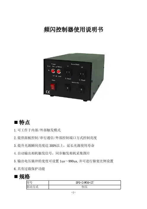
厦门智控
USUS-100 超声波测距模块
1. 概述
US-100 超声波测距模块可实现 0~4.5m 的非接触测距功能, 拥有 2.4~5.5V 的宽电压输入范围,静态功耗低于 2mA,自带温 度传感器对测距结果进行校正,同时具有 GPIO,等多种通信方 式,内带看门狗,工作稳定可靠。
2. 主要技术参数 电气参数
工作电压 静态电流 工作温度 输出方式 感应角度 探测距离 探测精度
USUS-100 超声波测距模块
DC 2.4V~5.5V 2mA -20~+70 度 电平或 UART(跳线帽选择) 小于 15 度 2cm-450cm 0.3cm+1%
本模块实物图及 实物图及尺寸 3. 本模块实物图及尺寸
本模块如图 3.1 和图 3.2 所示:
厦门智控
图 3.1: US-100 正面图
图 3.2:US-100 背面图
本模块的尺寸:45mm*20mm*1.6mm。
板上有两个半径为 1mm 的机械孔,如图 3.3 所示:
图 3.3:US-100 尺寸图
4. 接口说明
5 Pin 接口为 2.54mm 间距的弯排针,如图 4.1 所示:
厦门智控
图 4.2:5 Pin 接口 从左到右依次编号 1,2,3,4,5。
它们的定义如下: 1 号 Pin:接 VCC 电源(供电范围 2.4V~5.5V)。
2 号 Pin:接外部电路的 Trig 端。
3 号 Pin:接外部电路的 Echo 端。
4 号 Pin:接外部电路的地。
5 号 Pin:接外部电路的地。
电平触发测距 测距工作原理 5. 电平触发测距工作原理
电平触发测距的时序如图 5.1 所示:
10US
8 40K
图 5.1:US-100 测距时序图
厦门智控
图 5.1 表明:只需要在 Trig 管脚输入一个 10US 以上的高 电平,系统便可发出 8 个 40KHZ 的超声波脉冲,然后检测回波 信号。
当检测到回波信号后,模块还要进行温度值的测量,然 后根据当前温度对测距结果进行校正,将校正后的结果通过 Echo 管脚输出。
在此模式下,模块将距离值转化为 340m/s 时的时间值的 2 倍, 通过 Echo 端输出一高电平, 可根据此高电平的持续时间来 计算距离值。
即距离值为:(高电平时间*340m/s)/2。
注:因为距离值已经经过温度校正,此时无需再根据环境 温度对超声波声速进行校正,即不管温度多少,声速选择 340m/s 即可。
联系方式:159******** 廖先生 地址:福建厦门杏林北路 25 号 2 栋 网站:
淘宝店铺:
。