第三章 结构材料的力学性能及指标
- 格式:ppt
- 大小:86.00 KB
- 文档页数:16


3 Mechanical Properties (1)—1 Introduction and Concepts of Stress and strain教学目的:了解材料力学性能在实际中的应用,掌握表征材料力学性能的参数,施加载荷的类型;了解拉伸试验和测试的标准样品;熟练掌握工程应力和应变的概念。
教学重点:材料的工程应力和应变。
教学难点:剪切和扭转测试。
教学方法:多媒体和板书相结合。
学时分配:3.1 Introduction 30 min3.2 Concepts of stress and strain3.2.1 Tension tests 30 min3.2.2 Compression tests 10 min3.2.3 Shear and torsional tests 20 min教学过程与内容:3.1 Introduction回顾:性能与结构,性能与加工、制备间的关系。
Many materials, when in service, are subjected to forces or loads; examples include the aluminum alloy from which an airplane wing is constructed and the steel in an automobile axle. In such situations it is necessary to know the characteristics of the material and to design the member from which it is made such that any resulting deformation will not be excessive and fracture will not occur. The mechanical behavior of a material reflects the relationship between its response or deformation to an applied load or force. Important mechanical properties are strength, hardness, ductility, and stiffness.The mechanical properties of materials are ascertained by performing carefully designed laboratory experiments that replicate as nearly as possible the service conditions. Factors to be considered include the nature of the applied load and its duration, as well as the environmental conditions. It is possible for the load to be tensile, compressive, or shear, and its magnitude may be constant with time, or it may fluctuate continuously. Application time may be only a fraction of a second, or it may extend over a period of many years. Service temperature may be an importantfactor.Mechanical properties are of concern to a variety of parties (e.g., producers and consumers of materials, research organizations, and government agencies) that have differing interests. Consequently, it is imperative that there be some consistency in the manner in which tests are conducted, and in the interpretation of their results. This consistency is accomplished by using standardized testing techniques. Establishment and publication of these standards are often coordinated by professional societies.The role of structural engineers is to determine stresses and stress distributions within members that are subjected to well-defined loads. This may be accomplished by experimental testing techniques and/or by theoretical and mathematical stress analyses. These topics are treated in traditional stress analysis and strength of materials texts.Materials and metallurgical engineers, on the other hand, are concerned with producing and fabricating materials to meet service requirements as predicted by these stress analyses. This necessarily involves an understanding of the relationships between the microstructure (i.e., internal features) of materials and their mechanical properties.Materials are frequently chosen for structural applications because they have desirable combinations of mechanical characteristics. This chapter discusses the stress–strain behaviors of metals, ceramics, and polymers and the related mechanical properties; it also examines their other important mechanical characteristics.3.2 Concepts of stress and strainIf a load is static or changes relatively slowly with time and is applied uniformly over a cross section or surface of a member, the mechanical behavior may be ascertained by a simple stress–strain test; these are most commonly conducted for metals at room temperature. There are three principal ways in which a load may be applied: namely, tension, compression, and shear (Figures 3.1 a, b, c). In engineering practice many loads are torsional rather than pure shear; this type of loading is illustrated in Figure 3.1 d.Figure 3.13.2.1 Tension testsOne of the most common mechanical stress–strain tests is performed in tension. As will be seen, the tension test can be used to ascertain several mechanical properties of materials that are important in design. A specimen is deformed, usually to fracture, with a gradually increasing tensile load that is applied uniaxially along the long axis of a specimen. A standard tensile specimen is shown in Figure 3.2. Normally, the cross section is circular, but rectangular specimens are also used. During testing, deformation is confined to the narrow center region, which has a uniform cross section along its length. The standard diameter is approximately 12.8 mm, whereas the reduced section length should be at least four times this diameter; 60 mm is common. Gauge length is used in ductility computations; the standard value is 50 mm. The specimen is mounted by its ends into the holding grips of the testing apparatus. The tensile testing machine is designed to elongate the specimen at a constant rate, and to continuously and simultaneously measure the instantaneous applied load and the resulting elongations. A stress–strain test typically takes several minutes to perform and is destructive; that is, the test specimen is permanently deformed and usually fractured.Figure 3.2To minimize these geometrical factors, load and elongation are normalized to the respective parameters of engineering stress and engineering strain. Engineering stress σ is defined by the relationshipA F =σ (3.1) in which F is the instantaneous load applied perpendicular to the specimen cross section, in units of newtons (N), and A 0 is the original crosssectional area before any load is applied (m 2). The units of engineering stress are megapascals, MPa (SI).Engineering strain ε is defined according to00l l l l l i ∆=-=ε (3.2) in which l 0 is the original length before any load is applied, and l i is the instantaneous length. Sometimes the quantity l i - l 0 is denoted as Δl , and is the deformation elongation or change in length at some instant, as referenced to the original length. Engineering strain (subsequently called just strain) is unitless, but meters per meter or inches per inch are often used; the value of strain is obviously independent of the unit system.3.2.2 Compression testsCompression stress –strain tests may be conducted if in-service forces are of this type. A compression test is conducted in a manner similar to the tensile test, except that the force is compressive and the specimen contracts along the direction of the stress. Equations 3.1 and 3.2 are utilized to compute compressive stress and strain, respectively. By convention, a compressive force is taken to be negative, which yields a negative stress. Furthermore, since l 0 is greater than l i , compressive strains computed from Equation 3.2 are necessarily also negative. Tensile tests are more common because they are easier to perform; also, for most materials used in structural applications, very little additional information is obtained from compressive tests. Compressive tests are used when a material’s behavior under large and permanent (i.e., plastic) strains is desired, as in manufacturing applications, or when the material is brittle in tension.3.2.3 shear and torsional testsFor tests performed using a pure shear force as shown in Figure 3.1c, the shearstress τ is computed according toA F =τ (3.3) where F is the load or force imposed parallel to the upper and lower faces, each of which has an area of A 0 . The shear strain γ is defined as the tangent of the strain angle θ, as indicated in the figure. The units for shear stress and strain are the same as for their tensile counterparts. Torsion is a variation of pure shear, wherein a structural member is twisted in the manner of Figure 3.1d; torsional forces produce a rotational motion about the longitudinal axis of one end of the member relative to the other end. Examples of torsion are found for machine axles and drive shafts, and also for twist drills. Torsional tests are normally performed on cylindrical solid shafts or tubes. A shear stress τ is a function of the applied torque T , whereas shear strain γ is related to the angle of twist, ф in Figure 3.1d.Brief Summary总结本节讲的主要内容,及其重点。


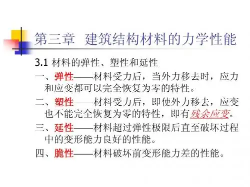

第三章 材料的力学性能第一节 拉伸或压缩时材料的力学性能一、概述分析构件的强度时,除计算应力外,还应了解材料的力学性质(Mechanicaiproperty ),材料的力学性质也称为机械性质,是指材料在外力作用下表现出的变形、破坏等方面的特性。
它要由实验来测定。
在室温下,以缓慢平稳的方式进行试验,称为常温静载试验,是测定材料力学性质的基本试验。
为了便于比较不同材料的试验结果,对试件的形状、加工精度、加载速度、试验环境等,国家标准规定了相应变形形式下的试验规范。
本章只研究材料的宏观力学性质,不涉及材料成分及组织结构对材料力学性质的影响,并且由于工程中常用的材料品种很多,主要以低碳钢和铸铁为代表,介绍材料拉伸、压缩以及纯剪切时的力学性质。
二、低碳钢拉伸时的力学性质低碳钢是工程中使用最广泛的金属材料,同时它在常温静载条件下表现出来的力学性质也最具代表性。
低碳钢的拉伸试验按《金属拉伸试验方法》(GB/T228—2002)国家标准在万能材料试验机上进行。
标准试件(Standard specimen )有圆形和矩形两种类型,如图3-1所示。
试件上标记A 、B 两点之间的距离称为标距,记作l 0。
圆形试件标距l 0与直径d 0有两种比例,即l 0=10d 0和l 0=5d 0。
矩形试件也有两种标准,即00l l ==其中A 0为矩形试件的截面面积。
试件装在试验机上,对试件缓慢加拉力F P ,对应着每一个拉力F P ,试件标距l 0有一个伸长量Δl o 表示F P 和Δl 的关系曲线,称为拉伸图或F P —Δl 曲线。
如图3-2a ,由于F P —Δl 曲线与试件的尺寸有关,为了消除试件尺寸的影响,把拉力F P 除以试件横截面的原始面积A 0,得出正应力0P F A σ=为纵坐标;把伸长量Δl 除以标距的原始长度l 0,得出应变0l l ε∆=为横坐标,做图表示σ与ε的关系(图3-2b )称为应力——应变图或σ—ε曲线(Stress-strain curve )。