机械制造装备设计之组合机床总体设计
- 格式:pptx
- 大小:3.12 MB
- 文档页数:30


组合机床总体设计及液压夹具设计中原工学院毕业设计(论文)应用组合机床加工大批量零件,快捷高效,生产效率高是机械加工的发展方向。
本次设计任务是制定梳棉机箱体结合件的加工工艺、组合钻孔工序的工装设计、液压控制系统设计、组合机床设计。
在工艺制定过程中,通过生产批量的分析确定梳棉机箱体结合件的加工方案,并寻求最佳的工艺方案,借此说明了工艺在生产过程中的重要性;在组合钻孔工序的工装设计过程中,结合实例,介绍了夹具设计方法,特别是对孔的加工精度进行了探讨;在液压控制系统设计过程中,以双面钻孔组合机床为对象,依据液压系统设计的基本原理,拟出合理的液压系统图。
通过系统主要参数的计算确定了液压元件的规格;在组合机床设计过程中,结合具体实例和设计经验, 阐述了通用件(如液压滑台,动力箱等)的选取及专用部件(如主轴箱)的设计计算。
:组合机床多轴箱工艺钻夹具液压传动1中原工学院毕业设计(论文)AbstractThis paper introduces the design of the box joint part of carding machinedrill combination machine,which is widely used for its high efficiency. Thisdesign task includes five parts: working out processing technologyof jointpart of carding machine, design and assemble of drilling jig, design andassemble of main spindle box, design hydraulic control parts, design combination machine tool.During process planning, define the productive process of joint part ofcarding machine and find out the best process plan by analyzing productionlot, which show process planning is very important in product process; thispaper introduces experiences of attachment design by using apracticalexample.It focuses on discussing how to improve the precision of holeposition; using two sides bore modular machine tool as an object, accordingto the basic principle of the hydraulic system design, formulates thereasonable schematic diagram, the hydraulic pressure part specificationthrough computation of the system main parameters is determined; Somedesigning examples are analyzed in this paper, and the considerations arediscussed for designing compo site tools for machining holes during designingcombination machine tool, such as general parts’ (hydraulic slipperyplatform, driving force box, etc) selection and special use components’ (mainspindle box) design .: combination machine tool hydraulic transmission axleboxes handicraft drills clamp2中原工学院毕业设计(论文)1、毕业设计(论文)选题审批表2、毕业设计(论文)任务书3、毕业设计(论文)评审表一4、毕业设计(论文)评审表二5、毕业设计(论文)评审表三6、毕业设计(论文)答辩记录文摘.......................................................................................... 1 英文文摘................................................................................. 2 主要符号表.............................................................................. 5 第一章引言 (6)1.1本课题提出的背景及意义 (6)1.2国内研究现状 (6)1.3本论文的主要内容.................................................................. 6 第二章工艺方案的拟定 (7)2.1 梳棉机箱体结合件零件的工艺技术分析 (7)2.2 定位分析、基准选取及制定工艺路线.......................................... 8 第三章钻夹具设计 (11)3.1 梳棉机箱体结合件钻孔组合机床夹具分析.................................... 11 3.2 定位夹紧方案的确定............................................................... 11 3.3 刀具选择及切削用量的选取 (11)3.4 夹具体设计........................................................................... 13第四章组合机床总体设计 (17)4.1 被加工零件工序图 (17)4.2 加工示意图 (18)4.3 机床联系尺寸图 (19)4.4 机床分组.................................................................................21 第五章液压系统设计 (23)5.1液压压紧系统设计 (23)5.2 钻削进给液压系统设计...............................................................25 第六章多轴箱——右主轴箱设计 (30)6.1引言 (30)3中原工学院毕业设计(论文)6.2绘制多轴箱设计原始依据图............................................................30 第七章经济性分析........................................................................ 39 7.1箱体结合件加工工艺的制定: (39)7.2 夹具定位加紧分析: (39)7.3组合机床应用分析:........................................................................ 39 第八章结论和展望........................................................................ 41 参考文献..........................................................................................42 致谢................................................................................................ 43 附件 (44)4中原工学院毕业设计(论文)符号单位意义M 牛.米弯矩F 牛力n 转每分转速Z 齿数m 模数d 毫米直径v 米每秒速度S 转每毫米进给量L 毫米长度P 千瓦功率T 牛.米扭矩q 升每分流量p 帕压力t 秒时间5中原工学院毕业设计(论文)1.1梳棉机是棉纺工艺流程中的关键性机台,被称为纺纱工艺的“心脏”设备。

2009年5月23 日目录第一部分组合机床总体设计 (3)一、工艺方案的制定 (3)1.1零件工艺基面的选择 (3)1.2 加工工艺分析 (3)1.3 孔切削用量的选择 (3)二、机床配置型式和结构方案的确定 (4)三、组合机床方案图纸设计 (4)3.1被加工零件工序图 (4)3.2加工示意图 (5)3.2.1加工示意图的编制步骤 (6)3.3组合机床生产率的计算 (11)3.3.1生产率的计算和生产率计算卡的绘制 (11)3.4机床联系尺寸图的绘制 (13)3.4.1机床主要联系尺寸的确定 (14)第一部分组合机床总体设计一、工艺方案的制定1.1零件工艺基面的选择由于被加工零件(缝纫机体)是箱体类零件,所以我选择了“一面二孔”的定位方法。
该方法有以下特点:a、很简便的消除工件的六个自由读,使工件获得稳定的固定位置;b、有同时加工五个面的可能。
既能高度集中加工工序,又有利于提高各面上孔的位置精度;c、该方法可以作为从粗加工到精加工的全部工序加工的基准,使整个工艺过程实现基准统一;d、该方法使夹紧方便,夹紧机构简单。
容易使夹紧力对准支承,消除夹紧力引起工件变形对加工精度的影响。
为了保证零件的加工精度及技术要求,工艺基面必须规定相应的公差。
根据缝纫机体零件的大小,定位销孔径选择∅16,太小时,定位销很细,加工中易受力产生较大的变形。
销孔的精度为2级,两销孔中心距定为321毫米,其公差为±毫米。
0.061.2 加工工艺分析由于被加工零件只需要钻孔,所以该机床只有一个钻孔加工工艺。
而且钻孔深度不大,属于一般钻孔。
1.3 孔切削用量的选择由于该缝纫机体是铸铁件,而且硬度大概在200~241左右,根据下表选取切削用量。
表1用高速钢钻头加工铸铁件的切削用量二、机床配置型式和结构方案的确定由于被加工的缝纫机体是一个箱体件,一次只加工一个,生产率要求不是很高,所以我选择了单工位组合机床,而且该零件孔中心线与定位基准面平行,而且需要同时加工两个面,因此选择单工位组合机床中的卧式双面组合机床。
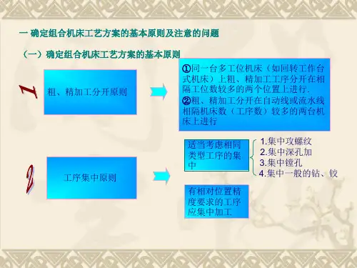
变速器上盖组合机床总体设计摘要组合机床是根据工件加工需要,以大量通用部件为基础,配以少量专用部件组成的一种高效专用机床。
目前,组合机床主要用于平面加工和孔加工两类工序。
而且其生产效率高,加工精度稳定,自动化程度高,使工人劳动强度降低。
由于本次加工的零件为变速器箱体,为大批量生产,而且所要加工的孔较多,本次设计的组合机床主要是对孔进行加工。
此设计绘制的是机床联系尺寸总图。
它是以被加工零件工序图和加工示意图为依据,并初步按选定的主要通用部件以及确定的专用部件的总体结构而绘制的。
是用来表示机床的配置形式,主要构成及各部件安装位置,相互联系,运动关系的总体布局图。
由于组合机床进行加工能够进行多工位加工,提高自动化程度,缩短加工时间和辅助时间。
而且组合机床大部分都是由通用部件组成,研制周期较短,便于设计,制造和使用维护,成本低。
而且机床易于改造,产品和工艺变化时,通用部件还能重复利用,经济性较好。
所以组合机床在大批量生产中的应用十分广泛。
关键词:组合机床,机床总图,自动化The overall design of combination machine tools for the cover oftransmissionABSTRACTThe assembly machine processes is according to the requirement of work pieces , and it is made of a lot of general use parts and a little exclusive use parts and it is a kind of a efficiently production machine. The present, assembly machine tool primarily is used in making the plane surface and the apertures. And because of high production efficiency, the accuracy of process, the stability of it's result, the automation extent higher, and so it can debase the strength of the labour.Because this parts for processing is transmission box, there is a lot of apertures in the part , and want that the processed bore is more, so the main process is making the holes.The design draw's is a total diagram of size of contact of tool machine. It is with was process the spare parts work preface diagram and process sketch map is basis, and the first step press the total structure of the main and in general use parts and certain appropriation parts that make selection but draw of. Is to use to mean that the tool machine installs the form, main composing and each parts install the position, contacting mutually, exercise total layout diagram of relation.Because the assembly machine tool can process some parts together ,so it can boost to automate extent, and shorten the time of process,And that assembly machine tool is made of a lot of general use parts, short the time of design, and it is convenient for designing, fabrication , the cost is low. And the machine tool is apt to be reconstructed, When the technics route changes, the general parts can be reused again, so we use assemble machine tool is economical .So large numbers of assembly machine tools are applied in the machine industrial.KEY WORDS: assembled machine tool,two-sided,active boring board,total diagram of tool machine,automation目录第1章组合机床理论基础 (5)1.1机床在国民经济的地位 (5)1.2组合机床的组成及特点 (5)1.3 组合机床研究基本内容 (6)第2章组合机床方案的制定 (7)2.1 组合机床的工艺范围及配置形式 (7)2.1.1 组合机床工艺范围 (7)2.1.2 组合机床配置形式 (7)2.2 组合机床工艺方案的拟定 (8)2.2.1 确定工艺方案的基本原则 (8)2.2.2 确定工艺方案应注意的问题 (8)第3章组合机床总体设计 (10)3.1 被加工零件工序图 (10)3.1.1 被加工零件工序图的作用与内容 (10)3.1.2 加工零件要求 (10)3.2组合机床切削用量 (11)3.2.1 确定切削用量应注意的问题 (11)3.2.2 切削用量的计算 (12)第4章加工示意图 (14)4.1 加工示意图的作用和内容 (14)4.2刀具,工具,导向装置的选择 (15)4.2.1刀具的选择 (15)4.2.2接杆的选择 (15)4.2.3导向套的选择 (15)4.3初定主轴类型、尺寸和外伸长度 (16)4.4动力部件的工作循环及工作行程的确定 (16)第5章机床联系尺寸图及生产率计算卡 (18)5.1 机床动力部件的选择 (18)5.1.1 动力箱的选择 (18)5.1.2 动力滑台的选择及附属部件 (19)5.2 确定机床尺寸 (21)5.2.1 确定装料高度 (21)5.2.2 中间底座轮廓尺寸 (21)5.2.3 多轴箱轮廓尺寸 (22)5.2 确定机床尺寸 (23)5.3 机床生产率计算卡 (24)结论 (27)谢辞 (28)参考文献 (29)第1章组合机床理论基础1.1机床在国民经济的地位随着现代化工业技术的快速发展,特别是随着它在自动化领域内的快速发展,组合机床的研究已经成为当今机器制造界的一个重要方向,在现代工业运用中,大多数机器的设计和制造都是用机床大批量完成的。
毕业设计题目:两缸柴油机机体8-M8螺纹底孔组合钻床的总体设计及主轴箱设计学科部:___________________________________专业:____________________________________班级:____________________________________学号:____________________________________学生姓名:_________________________________指导教师:_________________________________起讫日期:_________________________________中文摘要本次设计是对卧式单面8 轴组合钻床的设计,设计的内容包括组合钻床的总体设计以及多轴箱的设计。
组合钻床的总体设计主要是“三图”的设计。
三图的设计包括:被加工零件工序图、加工示意图、机床联系尺寸图。
多轴箱的设计关键是传动系统方案的确定。
再根据传动系统图确定手柄轴和油泵轴的位置安排,然后进行坐标计算,绘制多轴箱装配总图,箱体补充加工图,前盖补充加工图、最后根据上面的内容设计组合钻床。
关键子字:组合钻床、多轴箱、被加工零件工序图、加工示意图、机床联系尺寸图。
外文摘要This design is to horizontal axis combination drilling machine of single anddesign, the design of content including combination drilling machine of the overall design and the design of the spindle box. Combination drilling machine of the overall design mainly is the "three figure" design. The design of the three figure includes: processing parts process diagram, processing schemes, machine tool contact size figure. The design of the spindle box is key to the scheme determination of transmission system. Again according to the transmission system graph determine the handle axis and oil pump shaft placement, and then coordinate calculation, draw spindle box of general assembly, the casing is added processing figure, the front cover added processing diagram, according to the content of the above design combination drilling machine.Key son word : combination drilling machine, spindle box, be processing parts process diagram, processing schemes, machine tool contact size figure.、尸■、亠前言组合机床是用按系列化标准化设计的通用部件和按被加工零件的形状及加工工艺要求设计的专用部件组成的专用机床。

1、选择题1、工艺装备是机械加工中所使用的刀具、模具、机床夹具、量具和刀具的总称。
2、公比ψ值小则相对转速损失小(大、小、不变)。
3、组合机床总体设计的“三图一卡”是指被加工零件工序图、加工示意图、机床联系尺寸图和生产率计算卡。
4、进给运动消耗的功率远小于主传动功率(大、小、不变)。
5、转速图中“一点三线”。
一点指转速点,三线是指主轴转速线、传动轴线和传动线。
6、公比ψ值小,当变速范围一定时变速级数将增多。
(增多、减少、不变)7、机床精度包括几何精度、传动精度、运动精度、定位和重复定位精度、工作精度和精度保持性等。
8、拉刀的拉削方式可分为分层式、分块式和组合式三种。
2、选择题1、为防止爬行,在设计低速运动部件时,主要应采取下列那项措施。
[ D ]。
A. 提高传动精度B. 提高抗振能力C. 减少热变形D. 减少静、动摩擦系数之差2、下列哪一项不属于主变速传动系设计中扩大变速范围的方法。
[ D ]。
A.增加变速组B. 采用分支传动C.采用双公比传动系D. 采用交换齿轮3、设计机床主变速传动系时,为避免扩大传动误差,减少振动噪声,一般限制直齿圆柱齿轮的最大升速比 [ A ]。
4、最大相对转速损失率为21%的标准公比ψ是 [ B ]。
A. 1.12B. 1.26C. 1.41D. 1.585、下列哪一项属于主变速传动系设计中扩大变速范围最常用的方法。
[ C ]。
A.增加变速组B. 采用分支传动C.采用双公比传动系D. 采用交换齿轮3、简答题1、试述分级主轴变速箱设计的一般原则?答:(1)传动副前多后少的原则:主变速传动系统从电动机到主轴,通常为降速传动。
接近电动机传动件转速较高,根据公式可知,传动的转矩M较小,尺寸小些,因此,在拟定主变速系统时,尽可能将传动副较多的变速组安排在前面。
(2)传动顺序与扩大顺序相一致的原则:当各传动轴最高转速相同时,前密可使最低转速提高,从而减少传动件尺寸。
(3)变数组的降速要前慢后快,中间轴的转速不宜超过电动机的转速。