基于松下FP0_PLC的MG995舵机控制系统实现
- 格式:pdf
- 大小:381.82 KB
- 文档页数:2

mg995舵机控制Chapter 1: IntroductionThe MG995 servo is a widely used motor in robotic systems due to its high torque, accuracy, and reliability. This chapter provides an overview of the significance and objectives of this paper, along with an introduction to the MG995 servo.1.1 Significance of the StudyThe MG995 servo has gained popularity in various robotic applications, including robotics arm, autonomous vehicles, and aerial drones. Its precise control and robust construction make it suitable for a wide range of tasks. Understanding the principles of controlling the MG995 servo is crucial for designing efficient and reliable robotic systems.1.2 ObjectivesThe objective of this paper is to explore the control methods and principles of the MG995 servo. By delving into the technical aspects and capabilities of this servo, we can gain insights into its potential applications and improve the overall performance of robot systems.Chapter 2: MG995 Servo MechanicsIn this chapter, we focus on the internal mechanics of the MG995 servo. Understanding its structure and principles of operation helps in comprehending its unique control requirements.2.1 Internal StructureThe MG995 servo consists of a DC motor, gears, a potentiometer, and a control circuit. The gear reduction system enhances torquewhile preserving accuracy. The potentiometer provides feedback to the control circuit, allowing for precise position control.2.2 Principles of OperationWhen a control signal is supplied to the MG995 servo, the control circuit adjusts the current flowing through the DC motor. This current, combined with the gear reduction system, generates the desired output torque. The potentiometer provides feedback on the servo's position, allowing for closed-loop control.Chapter 3: Control Methods for MG995 ServoThis chapter focuses on various control methods and techniques used to operate the MG995 servo effectively. We explore both open-loop and closed-loop control approaches.3.1 Open-Loop ControlOpen-loop control involves sending a specific control signal to move the servo to a predetermined position. However, due to external factors such as friction and load variations, open-loop control may result in positional errors. Nevertheless, it is suitable for simple applications where precise positioning is not critical. 3.2 Closed-Loop ControlClosed-loop control incorporates feedback from the potentiometer to continuously adjust the control signal until the desired position is achieved. Proportional-Integral-Derivative (PID) control is a commonly used technique in closed-loop control for MG995 servos. It allows for accurate and stable position control, compensating for external disturbances.Chapter 4: Applications and Future DirectionsThis final chapter discusses the practical applications of MG995 servos in various fields and identifies potential areas for future research and development.4.1 ApplicationsThe MG995 servo finds applications in robotics arms, walking robots, humanoid robots, autonomous vehicles, and aerial drones. It offers precise actuation, enabling these systems to perform complex tasks with high accuracy and reliability.4.2 Future DirectionsFuture research can focus on improving the MG995 servo's performance by exploring advanced control techniques, reducing positional errors, enhancing communication interfaces, and minimizing power consumption. Additionally, exploring the integration of MG995 servos with advanced artificial intelligence algorithms can enable more sophisticated and intelligent robotic systems.In conclusion, the MG995 servo is a versatile and high-performance motor widely used in robotics. This paper provides an overview of its mechanics, control methods, and potential applications. Understanding the control principles of the MG995 servo is crucial for designing efficient and reliable robotic systems. With further advancements, the MG995 servo holds immense potential to revolutionize the field of robotics.Chapter 1: Introduction1.1 Significance of the StudyThe MG995 servo is a crucial component in various fields of robotics, including industrial robotics, humanoid robots, and autonomous vehicles. Understanding the control methods and principles of the MG995 servo is significant as it allows researchers and engineers to optimize its performance, improve the accuracy of robotic systems, and enable them to perform complex tasks efficiently.1.2 ObjectivesThe objective of this paper is to delve into the technical aspects and capabilities of the MG995 servo. By exploring its internal mechanics and control methods, we can gain insights into its potential applications and provide guidelines for efficient and reliable integration of the servo into robotic systems. This paper aims to provide a comprehensive understanding of the MG995 servo, its control principles, and its role in the advancement of robotics.Chapter 2: MG995 Servo Mechanics2.1 Internal StructureThe internal structure of the MG995 servo consists of several key components. These include a DC motor, gear system, potentiometer, and control circuit. The DC motor is responsible for generating the necessary torque to drive the servo's movement. The gear system provides torque amplification and precise motion transmission. The potentiometer serves as a feedback device, constantly measuring the position of the servo, allowing for accurate control. The control circuit processes the control signal and adjusts the electrical current to the motor accordingly.2.2 Principles of OperationThe MG995 servo operates based on the principles of electrical and mechanical systems. When a control signal is applied to the servo, the control circuit adjusts the electrical current flowing through the motor coils. This current generates a magnetic field that interacts with the permanent magnet inside the motor, resulting in rotational motion. The gear system amplifies the torque generated by the motor, allowing for precise movement control. The potentiometer provides position feedback to the control circuit, enabling closed-loop control.Chapter 3: Control Methods for MG995 Servo3.1 Open-Loop ControlOpen-loop control is a basic control method where a control signal is sent to the servo without considering feedback from the potentiometer. While open-loop control is simple to implement, it may result in positional errors due to external factors such as friction and load variations. This control method is suitable for applications where precise positioning is not critical, such as controlling the opening and closing of a robot gripper or adjusting the orientation of a camera.3.2 Closed-Loop ControlClosed-loop control incorporates feedback from the potentiometer, allowing for more accurate position control. Proportional-Integral-Derivative (PID) control is a commonly used technique in closed-loop control for MG995 servos. It continuously adjusts the control signal based on the difference between the desired position and theactual position measured by the potentiometer. By taking into account the history of error and the rate of change, PID control ensures stability and improves the servo's response to external disturbances.Chapter 4: Applications and Future Directions4.1 ApplicationsThe MG995 servo has countless applications in the field of robotics. Its high torque and accurate control make it suitable for tasks that require precise movement and manipulation. In industrial robotics, the MG995 servo can be used to control robotic arms for assembly, handling, and welding operations. In the field of humanoid robotics, it can be employed to control the joints of humanoid robots, enabling them to mimic human movements. Furthermore, in autonomous vehicles and aerial drones, theMG995 servo can be used to control steering mechanisms, camera gimbals, and flight control surfaces.4.2 Future DirectionsFuture research and development of the MG995 servo can focus on several areas. Firstly, advanced control techniques can be explored to improve its performance, such as adaptive control algorithms and nonlinear control methods. Secondly, efforts can be made to reduce positional errors by enhancing the mechanical design and minimizing backlash in the gear system. Additionally, improving communication interfaces and integrating the MG995 servo with advanced artificial intelligence algorithms can enhance its capabilities and enable more sophisticated and intelligent robotic systems. Moreover, research can be conducted to optimize powerconsumption and develop energy-efficient control strategies for the servo.In conclusion, the MG995 servo is a versatile and high-performance motor widely used in robotics. This paper has provided an overview of its internal mechanics, control methods, and potential applications. By understanding the principles of controlling the MG995 servo, researchers and engineers can optimize its performance, improve the accuracy of robotic systems, and enable more efficient and reliable task execution. With further advancements and developments, the MG995 servo holds immense potential to contribute to the advancement of robotics in various fields.。

mg995舵机中文资料(参数_尺寸_控制程序)
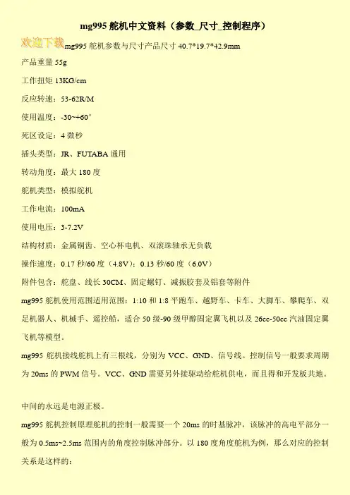
mg995舵机参数与尺寸产品尺寸40.7*19.7*42.9mm
产品重量55g
工作扭矩13KG/cm
反应转速:53-62R/M
使用温度:-30~+60°
死区设定:4微秒
插头类型:JR、FUTABA通用
转动角度:最大180度
舵机类型:模拟舵机
工作电流:100mA
使用电压:3-7.2V
结构材质:金属铜齿、空心杯电机、双滚珠轴承无负载
操作速度:0.17秒/60度(4.8V);0.13秒/60度(6.0V)
附件包含:舵盘、线长30CM、固定螺钉、减振胶套及铝套等附件
mg995舵机使用范围适用范围:1:10和1:8平跑车、越野车、卡车、大脚车、攀爬车、双足机器人、机械手、遥控船,适合50级-90级甲醇固定翼飞机以及26cc-50cc汽油固定翼飞机等模型。
mg995舵机接线舵机上有三根线,分别为VCC、GND、信号线。
控制信号一般要求周期为20ms的PWM信号。
VCC、GND需要另外接驱动给舵机供电,而且得和开发板共地。
中间的永远是电源正极。
mg995舵机控制原理舵机的控制一般需要一个20ms的时基脉冲,该脉冲的高电平部分一般为0.5ms~2.5ms范围内的角度控制脉冲部分。
以180度角度舵机为例,那么对应的控制关系是这样的:。

舵机的工作原理:控制信号由接收机的通道进入信号调制芯片,获得直流偏置电压。
它内部有一个基准电路,产生周期为20ms,宽度为 1.5ms的基准信号,将获得的直流偏置电压与电位器的电压比较,获得电压差输出。
最后,电压差的正负输出到电机驱动芯片决定电机的正反转。
当电机转速一定时,通过级联减速齿轮带动电位器旋转,使得电压差为0,电机停止转动。
当然我们可以不用去了解它的具体工作原理,知道它的控制原理就够了。
就象我们使用晶体管一样,知道可以拿它来做开关管或放大管就行了,至于管内的电子具体怎么流动是可以完全不用去考虑的。
舵机的控制:舵机的控制一般需要一个20ms的时基脉冲,该脉冲的高电平部分一般为0.5ms~2.5ms范围内的角度控制脉冲部分。
以180度角度舵机为例,那么对应的控制关系是这样的:0.5ms--------------0度;1.0ms------------45度;1.5ms------------90度;2.0ms-----------135度;2.5ms-----------180度;请看下形象描述吧:舵机的工作电压和电流:每一款舵机都有自己的参数,如TR213舵机的工作电压是 4.8-7.2V,TR205舵机的工作电压是 4.8-6V,电压不能超过这个范围,否则会很容易烧坏舵机,在不清楚舵机工作电压范围的情况下,建议使用5V给舵机供电。
舵机的工作电流是根据舵机的实际情况而定的,如TR213舵机,在空载的时候电流几乎为0,而在正常负载的情况下,电流在0.5A左右,视实际情况而定。
六足机器人需要18个TR213金属舵机,需要提高的电流大概在8A左右,如果电源功率不够会影响舵机的性能,最常见的现象是,当一个舵机负载的时候,其他舵机会出现混乱,无规律的乱摆。
舵机三根线的区分:信号线接单片机I/O口,由于舵机内部有驱动电路,所以可以直接用普通的单片机I/O口直接控制;电源正极,接输入电源的正极;地线,接输入电源的负极;备注:如果控制部分和电源部分是分开的,两者一定要共地。
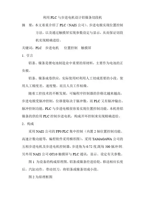
利用PLC与步进电机设计铝镍条切段机摘要:本文着重介绍了PLC(NAIS公司)、步进电极实现位置控制方法,以及通过触摸屏实现参数设定与显示,从而保证切段机实现精确进给。
关键词:PLC 步进电机位置控制触摸屏1.引言铝条、镍条是锂电池制造业中重要的原材料,主要作为电池的正负极。
铝条、镍条成卷供应,实际使用时利用人工切成需要的小段。
使用人工精度差,速度慢。
而且人员工作枯燥。
随着工控技术的不断发展,可编程序控制器的价格比越来越高,步进电极受脉冲控制,位移量取决于脉冲数,而PLC又有脉冲输出、脉冲控制功能,PLC与步进电极很容易实现位置控制功能。
本机将铝镍条的供给用PLC控制步进电机,构成开环控制来实现精确进给。
2.构成采用NAIS公司的FP0 PLC集中控制(内置2轴位置控制功能、高速计数功能等,编程软件采用梯形图),采用TAMAGAWA公司的五相步进电机及步进电机控制器,步进角为0.72度,既每500脉冲/转.另外用NAIS公司GT10触摸屏与PLC通讯,显示、设定有关参数。
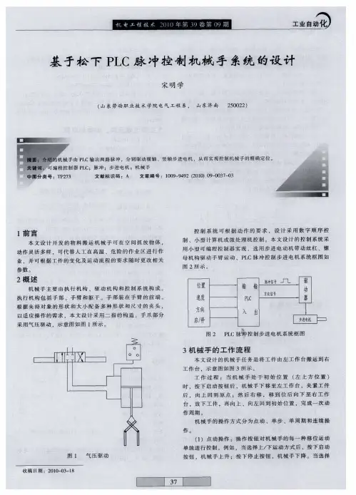
图1 为设备的构成原理图。
铝条或镍条经进给轮,移送相应长度后,汽缸动作,带动切刀,将铝条或镍条切成小段。
图2为原理框图3.系统设计因为本系统只有一台步进电机,所以只有1轴位置控制,其中Y0为PLC 位置通道1的脉冲输出端子,Y2为方向控制端子,X0为原点输入端子。
利用速度及位置控制指令F168(SPD1)可以方便的实现步进电机的转速,旋转量等的控制,从而控制铝条或镍条的长度。
并且进给轮连续运行,不须要原点复位及绝对值位置控制。
只要在原来的基础上相对位移多长的距离就可以了。
步进电机与进给轮用1:1驱动。
而步进电机为500脉冲/转。
知铝条卷汽缸进给轮步进电机切刀图1 系统构成道需要步进的距离,及进给轮的半径就可以计算需要多少个脉冲。
本设计中进给轮周长为50mm ,即每个脉冲为0.1mm 。
本设计中对于步进的精度要求不是很高,0.1已经足够。
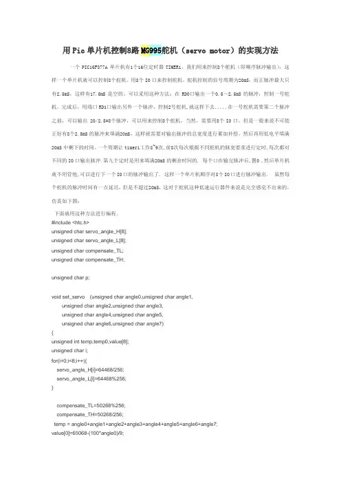
用Pic单片机控制8路MG995舵机(servo motor)的实现方法一个PIC16F877A单片机有1个16位定时器TIMER1,我们用来控制8个舵机(即顺序脉冲输出),这样一个单片机就可以控制8个舵机。
用8个IO口来控制舵机,舵机控制的信号周期为20mS,而正脉冲最大只有2.5mS,这样有17.5mS是空的。
可以采用这种方法:在RD0口输出一个0.5~2.5mS的脉冲,控制一号舵机。
完成后,用端口RD1口输出另外一个脉冲,控制2号舵机,就这样下去.....在一号舵机需要第二个脉冲之前,可以输出 20/2.5=8个脉冲,可以用来控制8个舵机,当然,需要用8个IO口。
但是一般来说不可能正好有8个2.5mS的脉冲来填满20mS,这样就需要对输出脉冲的总宽度进行累加补偿,然后再用低电平填满20mS中剩下的时间。
一个周期让timer1工作8~9次,前8次每次根据不同舵机的脉宽要求进行定时,每次都对不同的IO口输出脉冲.第九个定时是用来填满20mS的剩余时间的. 每个口在输完脉冲后,置0 ,然后单片机就不用管他,可以进行下一个IO口的脉冲输出了. 这样一个单片机顺序对8个IO口进行脉冲输出. 虽然每个舵机的脉冲时间有一点延迟,但是不超过20mS,这对于舵机这种低速运行器件来说是完全感觉不出来的。
仿真如下图:下面就用这种方法进行编程。
#include <htc.h>unsigned char servo_angle_H[8];unsigned char servo_angle_L[8];unsigned char compensate_TL;unsigned char compensate_TH;unsigned char p;void set_servo (unsigned char angle0,unsigned char angle1,unsigned char angle2,unsigned char angle3,unsigned char angle4,unsigned char angle5,unsigned char angle6,unsigned char angle7){unsigned int temp,temp0,value[8];unsigned char i;for(i=0;i<8;i++){servo_angle_H[i]=64468/256;servo_angle_L[i]=64468%256;}compensate_TL=50268%256;compensate_TH=50268/256;temp = angle0+angle1+angle2+angle3+angle4+angle5+angle6+angle7;value[0]=65068-(100*angle0)/9;value[1]=65068-(100*angle1)/9;value[2]=65068-(100*angle2)/9;value[3]=65068-(100*angle3)/9;value[4]=65068-(100*angle4)/9;value[5]=65068-(100*angle5)/9;value[6]=65068-(100*angle6)/9;value[7]=65068-(100*angle7)/9;for(i=0;i<8;i++){servo_angle_H[i]=value[i]/256;servo_angle_L[i]=value[i]%256;}temp0=46068+(100*temp)/9;compensate_TL=temp0%256;compensate_TH=temp0/256;}//主程序***********************************************************************void main(void){unsigned int a;unsigned int b;INTCON=0;GIE=1;// ;打开总中断PEIE=1;// ;打开外部中断使能位TMR1IE=1;// ;打开TMR1中断TRISD=0X00;PORTD= 0X00;//脉冲波形起始状态T1CON=0x01;//设置TMR1的控制字TMR1IF=0;unsigned char i;set_servo (13,34,56,87,80,123,156,13);while(1){; }}//中断服务程序*************************************************************void interrupt timer1(void){TMR1IF=~TMR1IF;switch(p){case 0: TMR1L=servo_angle_L[p];TMR1H=servo_angle_H[p];PORTD=0X01; break;case 1: TMR1L=servo_angle_L[p];TMR1H=servo_angle_H[p];PORTD=0B00000010; break;case 2: TMR1L=servo_angle_L[p];TMR1H=servo_angle_H[p];PORTD=0B00000100; break;case 3: TMR1L=servo_angle_L[p];TMR1H=servo_angle_H[p];PORTD=0B00001000; break;case 4: TMR1L=servo_angle_L[p];TMR1H=servo_angle_H[p];PORTD=0B00010000; break;case 5: TMR1L=servo_angle_L[p];TMR1H=servo_angle_H[p];PORTD=0B00100000; break;case 6: TMR1L=servo_angle_L[p];TMR1H=servo_angle_H[p];PORTD=0B01000000; break;case 7: TMR1L=servo_angle_L[p];TMR1H=servo_angle_H[p];PORTD=0B10000000; break;default:TMR1L=compensate_TL;TMR1H=compensate_TH;PORTD=0B00000000;p=0; break;}p++;}。

松下PLC控制伺服电机实例程序上位机设定伺服电机旋转速度单位为<转/分),伺服电机设定为1000个脉冲转一圈.PLC输出脉冲频率=< 速度设定值/6)*100<HZ).上位机设定伺服电机行走长度单位为(0.1mm>,伺服电机每转一圈地行走长度10mm,伺服电机转一圈需要地脉冲数为1000, 故PLC发出一个脉冲地行走长度为0.01mm(一个丝>.PLC输出脉冲数=长度设定值*10.上面两点地计算都是在伺服电机参数设定完地基础上得岀地.也就是说,在计算PLC发岀脉冲频率与脉冲前,必须先根据机械条件,综合考虑精度与速度要求设定好伺服电机地电子齿轮比!大致方法如下:机械安装结束,伺服电机转动一圈地行走长度已经固定<如上面所说地10mm ),设计要求地行走精度为0.1mm(10个丝>.为了保证此精度,一般情况下是让一个脉冲地行走长度低于0.1mm,如设定一个脉冲地行走长度为如上所述地0.01mm,于是电机转一圈所需要脉冲数即为1000个脉冲.此种设定当电机速度要求为1200转/分时,PLC应该发出地脉冲频率为20K.松下PLC 地CPU本体可以发脉冲频率为100K,完全可以满足要求.如果电机转动一圈为100mm,设定一个脉冲行走仍然是0.01mm,电机转一圈所需要脉冲数即为10000个脉冲,电机速度为1200转时所需要脉冲频率就是200K.PLC地CPU本体就不够了.需要加大成本,如增加脉冲输出专用模块等方式.知道了频率与脉冲数地算法就简单了,只需应用PLC地相应脉冲指令发出脉冲即可,松下PLC地程序图如下:松下伺服常见问题一、基本接线主电源输入采用〜220V,从L1、L3接入<实际使用应参照操作手册);控制电源输入r、t也可直接接〜220V。
电机接线见操作手册第22、23页,编码器接线见操作手册第24〜26页,切勿接错.二、试机步骤1.JOG试机功能仅按基本接线就可试机;在数码显示为初始状态’r 0 '下,按’SET键,然后连续按’MODE键直至数码显示为’AF-AcL',然后按上、下键至’AF- JoG。
•舵机的工作原理:控制信号由接收机的通道进入信号调制芯片,获得直流偏置电压。
它内部有一个基准电路,产生周期为20ms,宽度为1.5ms的基准信号,将获得的直流偏置电压与电位器的电压比较,获得电压差输出。
最后,电压差的正负输出到电机驱动芯片决定电机的正反转。
当电机转速一定时,通过级联减速齿轮带动电位器旋转,使得电压差为0,电机停止转动。
当然我们可以不用去了解它的具体工作原理,知道它的控制原理就够了。
就象我们使用晶体管一样,知道可以拿它来做开关管或放大管就行了,至于管内的电子具体怎么流动是可以完全不用去考虑的。
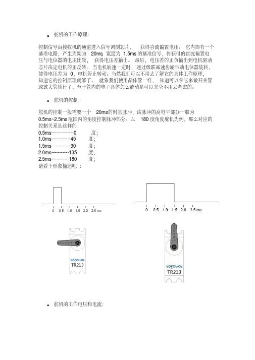
•舵机的控制:舵机的控制一般需要一个20ms的时基脉冲,该脉冲的高电平部分一般为0.5ms~2.5ms范围内的角度控制脉冲部分。
以180度角度舵机为例,那么对应的控制关系是这样的:0.5ms--------------0度;1.0ms------------45度;1.5ms------------90度;2.0ms-----------135度;2.5ms-----------180度;请看下形象描述吧:•舵机的工作电压和电流:每一款舵机都有自己的参数,如TR213舵机的工作电压是4.8-7.2V,TR205舵机的工作电压是4.8-6V,电压不能超过这个范围,否则会很容易烧坏舵机,在不清楚舵机工作电压范围的情况下,建议使用5V给舵机供电。
舵机的工作电流是根据舵机的实际情况而定的,如TR213舵机,在空载的时候电流几乎为0,而在正常负载的情况下,电流在0.5A左右,视实际情况而定。
六足机器人需要18个TR213金属舵机,需要提高的电流大概在8A左右,如果电源功率不够会影响舵机的性能,最常见的现象是,当一个舵机负载的时候,其他舵机会出现混乱,无规律的乱摆。
•舵机三根线的区分:信号线接单片机I/O口,由于舵机内部有驱动电路,所以可以直接用普通的单片机I/O口直接控制;电源正极,接输入电源的正极;地线,接输入电源的负极;备注:如果控制部分和电源部分是分开的,两者一定要共地。