基于51单片机的智能照明控制系统设计毕业设计演示
- 格式:ppt
- 大小:296.50 KB
- 文档页数:39
基于51单片机的楼体彩灯控制系统摘要随着社会的进步,人们的审美眼光不断提升,城市的景观建设也备受人们重视。
房地产的崛起让城市的楼层越来越高,单调的混凝土让城市的夜晚变得单调。
然而,伴随着城市越来越多的工程亮化工作的增多,越来越多的城市面积扩大,集中性的维护以及管理城市以及景观的亮化工作也变得越来越迫切,常常有不少城市的楼体亮化或景区的亮化在平常时不愿意开启,只有周末或者在国家法定节假日开启,这样一来更加造成了维护人员的困难。
基于51单片机的楼体彩灯控制系统,其总体架构是由一个51主控板采用80C51和多个51单片机控制节点所组成,主控板通过无线发射模块发射信号给子节点,子节点收到信号后通过MCU的I/O口来控制继电器来实现远程控制楼体彩灯开关,与此同时,子节点单片机将此节点彩灯的开关信号发送给主控板。
其中主控板用来处理复杂的子节点信号,通过内部算法进行实时有效的控制整栋楼甚至是多栋楼的亮灯效果。
伴随着科技的进步计算机在社会各个方面开始大规模应用,单片机随着集成电路的发展越来越便捷,操作更加简单,体积越来越小,功能越来越多,在生活上的应用随处可见。
更是随着智能家居的口号越来越响,单片机和A/D 芯片应用更是与日俱增。
如何让楼体彩灯控制智能化,引发了我们的思考。
本文阐述了以MCS-51单片机为核心控制的楼体亮化系统的设计方案。
该设计方案能够智能化控制楼体彩灯,极大的节省了人力成本,并且能很好的实现楼体美化以及很好的广告效果。
关键词:MCS-51单片机楼体彩灯控制系统无线发射模块THE CONTROL CYSTERMOF FLOOR LANTERN BASEDON 51 MCUABSTRACTAs society progresses, people's aesthetic vision of continuous improvement, construction of urban landscape has attracted much attention. Rising real estate make the city more and more high floor, monotonous concrete to make the city at night becomes monotonous. However, with the increasing number of urban lighting engineering work increased, more and more cities expand the area of concentration of maintenance and management of urban and landscape lighting has also become more and more urgent, and often there is not House of the city's less scenic lighting lighting or unwilling to open during normal, open only on weekends or during a national holiday, so to create a more difficult maintenance personnel.51 microcontroller-based floor Lottery light control system, the overall architecture is composed of a 51 MPUs 80C51 MCU control node and a plurality of 51 composed of the main control board transmit signals through the wireless transmitter module to a child node, the child node receives a signal after the adoption of the MCU I / O port to control relay to remote control building Lottery light switch, at the same time, the child nodes of this node lights switch MCU signal to the control board. Wherein the main control board for processing complex signals child nodes, through effective internal algorithms for real-time control of the whole building and even more building's lighting effects.With the advancement of computer technology began large-scale applications in all aspects of society, with the development of single-chip integrated circuits more and more convenient, easier operation, smaller and smaller, more and more functions, used in daily life can be seen everywhere . With the smart home is getting louder and louder slogan, microcontroller and A /D chip applications is increasing. How to make floor lamps Lottery intelligent control, led us to thinking. In this paper, with MCS-51 microcontroller as the core control of the House of lighting system design.This design can be intelligently controlled House Lottery lights, greatly save labor costs, and can achieve a good building body beautification and good advertising effect.KEY WORDS:MCS-51 microcontroller House Lottery light control system Wireless transmitter module目录前言 (1)第1章绪论 ....................................................错误!未定义书签。
基于51单片机的红外线遥控智能台灯设计-智能台灯的控制系统电路设计摘要随着社会的发展,智能产品也随着变化,电子产品快速发展,我们家用电器智能化越来越多,常见的智能家居如电饭煲,电磁炉,台灯等主要系统都具有一个共同的特点,那就是利用单片机控制系统作为本次的核心系统,因此带来巨大的方便,本次针对智能家居的台灯控制系统设计,对我国的智能家居发展是十分必要的,有着巨大的市场价值和市场潜力。
本设计以STC89C52为控制芯片,通过对红外传感器和光敏电阻的输出信息信号采集实现对LED灯的控制,达到模拟控制灯光的目的。
论文的主要的目的是完成智能灯光的硬件设计和软件设计,硬件设计的选择包括选型和电路设计;软件是对硬件的每个部分模块进行驱动,对于软件程序的编写可以将硬件部分传感器的数据采集和控制输出功能,从而做到灯光的智能控制。
关键词:STC89C52,智能台灯,光敏电阻,红外传感器Design of infrared remote control intelligent table lamp based on 51 single chip microcomputer-The control system circuit design ofintelligent table lampAbstractWith the development of society, intelligent products are also changing, and electronic products are developing rapidly. More and more intelligent home appliances are used. Common intelligent home systems such as rice cooker, electromagnetic stove, table lamp and so on have a common feature. That is to use the single-chip microcomputer control system as the core system of this time, which brings great convenience. This time, for the intelligent home The design of lamp control system is very necessary for the development of smart home in China, and has great market value and market potential.This design is based on STC89C52 as the control chip, through the acquisition of the output information signal of photoresist and infrared sensor to achieve the control of LED lamp, to achieve the purpose of analog control of light. The main purpose of this paper isto complete the hardware design and software design of intelligent lighting. The choice of hardware design includes selection and circuit design. The software is to drive each part of the hardware module. For the preparation of software program, the data acquisition and control output function of the hardware part of the sensor can be achieved, so as to make the lighting intelligent control.Key words: STC89C52; intelligent table lamp; photosensitive resistance; infrared sensor目录1 绪论 (3)1.1 本设计研究背景 (3)1.2 本设计的目的和意义 (3)1.3 设计方案的提出 (2)2 总体方案的选择 (2)2.1 主控芯片的选择 (2)2.2 三极管驱动模块 (3)2.3 热释电红外传感器 (3)2.4 光敏电阻 (3)2.5 报警模块的选择 (4)2.6 按键控制模块 (4)2.7 信号处理模块的选择 (5)2.8 手势模块的选择 (5)2.9 智能灯光方案的确定 (5)3 硬件设计 .................................................. 错误!未定义书签。
摘要LED台灯作为LED绿色照明光源产品,作为国家绿色照明推广使用的产品。
随着时代发展,节能环保、健康与人们的日常生活变得密不可分,科技的进步,也使家电更加智能化和人性化。
台灯作为家电中基础的,也是必不可少的,所以,提出PWM调光灯设计。
该设计是以STC89C51RC单片机为控制核心的集多种功能于一体的智能LED台灯。
该台灯实现了光亮度具有手动、自动两种调节方式;具有呼吸模式功能,还具有红外遥控功能。
硬件设计部分分为单片机控制模块、按键模块、照明模块、光敏模块、LED指示模块、遥控模块等多个部分。
单片机主控制芯片选用STC89C51RC,LED指示模块选用三种不同颜色的小LED来指示不同的工作模式,通过按键模块来调整工作模式和LED的亮度,照明模块选用12草帽型白光LED,光敏模块选用ADC0809芯片实现对光敏信号的采集,并利用PWM 调光技术对LED进行光度的自动调节。
可以通过红外遥控远距离无线遥控,通过单片机C语言编程进行软件设计,综合实现了全部控制功能。
关键词LED台灯光度PWM调光自动调节AbstractLED lamp as LED green lighting products, as the country to promote the use of green lighting products. With the development of the times,energy saving and environmental protection, health and the peopledaily life are inseparable, the progress of science and technology,also makes home appliances more intelligent and humanized. The lamp as home appliances based, so is a lso essential,, put forward PWM dimming the lights design.The design is based on STC89C51RC SCM as control core and multi functions in one of the intelligent LED lamp. The table lamp realizes the brightness with manual, automatic two types of regulation;respiratory mode function, but also has the function of infrared remote control. The design of the hardware part consists of MCU control module, keyboard module, lighting module, photosensitive module,LED module, remote control module instruction. The MCU main control chip STC89C51RC, LED indicating module with three kinds ofdifferent colors of small LED to indicate different working modes,brightness through the key module to adjust the working mode and the LED lighting module, using 12 straw hat type white LED,photosensitive module uses ADC0809 chip implementation of a signal acquisition, automatic regulation and luminosity of LED using PWM dimming technology. Through the infrared remote control, wireless remote control, software design of the MCUC language programming,integrated control functions are realized by.Key wordLED lamp dimming automatically adjust luminosity of PWM目录5第1章绪论..................................................................................................................5 1.1 课题研究背景.........................................................................................................5 1.2 系统方案的提出.....................................................................................................51.2.1 LED优势......................................................................................................61.2.2 方案简述.......................................................................................................7第2章系统方案的选择...............................................................................................7 2.1 控制芯片的选择方案.............................................................................................72.1.1 STC89C51RC ...............................................................................................72.1.2 A VR单片机..................................................................................................82.1.3 FPGA ............................................................................................................2.1.4 主控制芯片的确定 (8)2.2 照明模块的选择.....................................................................................................882.2.1 三极管驱动...................................................................................................92.2.2 PWM芯片控制............................................................................................102.2.3 照明方案的确定.........................................................................................10 2.3 遥控模块的选择...................................................................................................102.3.1 超再生无线模块.........................................................................................2.3.2 红外遥控....................................................................................................112.3.3 遥控方案的确定 (11)12第3章硬件设计........................................................................................................3.1 单片机STC89C51芯片简介 (12)16 3.2 LED驱动电路....................................................................................................18 3.3 按键控制电路.......................................................................................................19 3.4 LED指示电路....................................................................................................19 3.5自动控制电路........................................................................................................203.5.1 光敏电路...................................................................................................203.5.2 ADC0809模数转换 .................................................................................21 3.6遥控电路................................................................................................................23第4章软件设计........................................................................................................23 4.1 Keil C51 ..............................................................................................................4.2 Protel99SE ..........................................................................................................2325 4.3 程序流程图...........................................................................................................26第5章调试................................................................................................................5.1 硬件调试...............................................................................................................2626 5.2 软件调试...............................................................................................................27第6章总结................................................................................................................28参考文献...................................................................................................................... 附录一:protel99se 原理图 (29)30附录二:源程序..........................................................................................................前言LED照明又称固态照明,作为继白炽灯、荧光灯后的第三代照明技术,具有节能、环保、安全可靠的特点,固态光源是被业界看好的未来十年替换传统照明器具极具潜力的新型光源,代表照明技术的未来。
编号: 毕业论文(设计)题目基于51单片机智能光控节能灯的设计毕业设计(论文)原创性声明和使用授权说明原创性声明本人郑重承诺:所呈交的毕业设计(论文),是我个人在指导教师的指导下进行的研究工作及取得的成果。
尽我所知,除文中特别加以标注和致谢的地方外,不包含其他人或组织已经发表或公布过的研究成果,也不包含我为获得及其它教育机构的学位或学历而使用过的材料.对本研究提供过帮助和做出过贡献的个人或集体,均已在文中作了明确的说明并表示了谢意。
作者签名: 日期:指导教师签名: 日期:使用授权说明本人完全了解大学关于收集、保存、使用毕业设计(论文)的规定,即:按照学校要求提交毕业设计(论文)的印刷本和电子版本;学校有权保存毕业设计(论文)的印刷本和电子版,并提供目录检索与阅览服务;学校可以采用影印、缩印、数字化或其它复制手段保存论文;在不以赢利为目的前提下,学校可以公布论文的部分或全部内容.作者签名:日期:学位论文原创性声明本人郑重声明:所呈交的论文是本人在导师的指导下独立进行研究所取得的研究成果。
除了文中特别加以标注引用的内容外,本论文不包含任何其他个人或集体已经发表或撰写的成果作品。
对本文的研究做出重要贡献的个人和集体,均已在文中以明确方式标明。
本人完全意识到本声明的法律后果由本人承担。
作者签名: 日期:年月日学位论文版权使用授权书本学位论文作者完全了解学校有关保留、使用学位论文的规定,同意学校保留并向国家有关部门或机构送交论文的复印件和电子版,允许论文被查阅和借阅.本人授权大学可以将本学位论文的全部或部分内容编入有关数据库进行检索,可以采用影印、缩印或扫描等复制手段保存和汇编本学位论文.涉密论文按学校规定处理.作者签名:日期:年月日导师签名: 日期:年月日德州学院毕业论文(设计)开题报告书三、课题设计方案系统总体设计方案:采用AT89S52单片机作为核心控制部件,利用时钟芯片DS1302对路灯进行定时控制,由光敏器件完成环境光照度的采集与路灯故障的检测,并通过LCD显示故障路灯编号,利用光电开关实现车流量的检测,根据环境光强度、车流量大小自动调节路灯亮灭情况,从而实现系统的智能化。
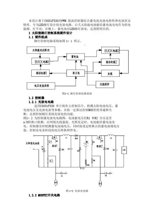
本设计基于C8051F330的PWM 限流控制器结合蓄电池充放电特性和电池伏安特性,专为LED路灯设计的充放电路。
白天太阳能电池板给蓄电池充电作为供电能源,灯不亮;在晚上,蓄电池对LED路灯放电,达到照明目的。
1 太阳能路灯控制系统硬件设计1.1 硬件组成路灯控制电路系统如图1- 1 所示。
图1-1 路灯控制电路系统1.2 控制器1.2.1 充放电电路选用C8051F330 单片机作主控制芯片,检测太阳电池电压、蓄电池电压及充放电流等参数,并按一定算法控制MOS管的导通和关断,达到控制路灯系统充放电的功能。
图1- 2 为控制器充放电电路图,电池板电压经R1 和R2 分压送至A/D转换口检测,以判别光线强弱。
光照充足时,电池板给蓄电池充电。
控制器实时检测蓄电池端电压,同时按设定转换点的蓄电池端电压值,控制充电各阶段的电压转换和停充。
图1-2 充放电电路1.2.2 MOSFET开关电路设计中用MOSFET 实现电路通断。
MOSFET 开关频率高适合作为PWM 控制充电开关。
采用N 沟道MOSFET ,导通电压Vth>0,由图1- 3 实现MOSFET 驱动。
R1 为基极限流电阻,C 为加速电容。
当输入信号上升、下降时,R1 电阻瞬间被旁路并提供基极电流,在晶体管由导通状态变化到截止状态时能够迅速从基区取出电子(因为R1 被旁路),消除开关的时间滞后,提高开关速度。
图1-3 MOSFET 驱动电路图1.3 电流采样电路通过康铜丝电阻采样的电压经LM358 放大输入单片机,进行数据的处理。
如下图1- 4 所示。
图1-4 电流的采样电路回路电流在康铜丝电阻上产生的压降输入到放大器的反向输入端。
其中 10-R R -U U R U R U -0V0U -U 1203231021====1.4 电源电路如图1- 5 所示,蓄电池电压经过R1 限流后输入到稳压器7812再通过IN4733 进行分压后,经稳压器AS117,将输出电压调至3.3V以供单片机工作。
摘要随着社会的发展人们对生活质量的要求越来越高,照明在能耗中所占的比例日益增加,因而照明节能也日显重要。
现在国内外普及使用的节能开关基本有声控型、触摸型、感光型等。
这几种开关各有自己的弊端,如声控型不适合环境嘈杂场所、感光型开关在无人期间不能自动关闭。
单片微型计算机简称单片机,是典型的嵌入式微控制器(Microcontroller Unit),常用英文字母的缩写MCU 表示单片机,单片机又称单片微控制器,它不是完成某一个逻辑功能的芯片,而是把一个计算机系统集成到一个芯片上。
单片机由运算器,控制器,存储器,输入输出设备构成,相当于一个微型的计算机(最小系统)。
和计算机相比,单片机缺少了外围设备等。
概括地讲:一块芯片就成了一台计算机。
它体积小、质量轻、价格便宜、为学习、应用和开发提供了便利条件。
同时,学习使用单片机是了解计算机原理与结构的最佳选择。
单片机在工业控制领域广泛应用。
单片机由仅有CPU的专用处理器芯片发展而来。
最早的设计理念是通过将大量外围设备和CPU集成在一个芯片中,使计算机系统更小,更容易集成到复杂的对体积要求严格的控制设备当中。
本文利用所学51单片机基础知识结合自动控制技术和蓝牙2.0通信技术设计完成一套无线遥控家电开关系统。
本设计详细地讲述了51单片机控制原理和单片机编程技术,HC-06蓝牙通信技术以及自动化控制技术。
整个系统以STC89C52单片机为核心,单片机实现HC-06蓝牙指令的解析与继电器开关控制指令的发出。
蓝牙通信单元采用工业级的HC-06蓝牙模块来完成,蓝牙模块在整个系统中负责蓝牙指令的接收和传输;家电开关的自动控制部分采用4路继电器开关来实现,继电器开关是典型的弱电信号控制型照明系统开关。
关键词:单片机、蓝牙、照明系统AbstractWith the development of society, people's quality of life is becoming more and more demanding, and the proportion of lighting in the energy consumption is increasing. Now the popularity of energy-saving switch at home and abroad, the basic use of voice control, touch type, sensitive type, etc.. These switches have their owndrawbacks, such as voice type is not suitable for noisy environment, photosensitive switch can not be automatically shut down during the unmanned. As the single chip computer is a typical embedded micro controller (Microcontroller Unit), usually abbreviated as MCU English letters single-chip microcontroller also known as single-chip microcontroller, it is not the completion of a logic function of the chip, but a computer system integrated into a chip. The single chip microcomputer is composed of an arithmetic device, a controller, a memory, an input and output device, which is equivalent to a microcomputer. Compared with the computer, SCM, such as the lack of peripherals. Generally speaking: a chip is a computer. The utility model has the advantages of small size, light weight, low cost and convenient conditions for learning, application and development. At the same time, learning to use the MCU is to understand the principle and structure of the computer the best choice.SCM is widely used in the field of industrial control. Single chip processor developed by only CPU dedicated chip. The first idea is to integrate a large number of peripherals and CPU in a single chip, so that the computer system is smaller, more easily integrated into the complex requirements of the control of the volume of equipment. In this paper, we design a set of wireless remote control switch system based on the 51 basic knowledge of MCU and the technology of Bluetooth and 2. This design describes in detail the 51 single-chip microcomputer control principle and single-chip programming technology, HC-06 Bluetooth communication technology and automation control technology. The whole system is based on STC89C52 single chip microcomputer, and the analysis of the HC-06 Bluetooth command and the control of the relay switch control instructions. Bluetooth communication unit using HC-06 Bluetooth module to complete the industrial level, the Bluetooth module is responsible for Bluetooth instruction in the whole system of receiving and transmission; automatic control appliance switch using 4 way relay switch to achieve the relay switch control is a typical type of weak current signal lighting system switch.Keywords: MCU, Bluetooth, lighting system摘要 (1)Abstract (1)1绪论 (4)1.1 课题研究的背景 (4)1.2 课题的研究意义 (5)2 体统的总体设计 (6)2.1 选择单片机 (6)2.2 蓝牙设备 (7)2.3 检测光照 (8)2.4 继电器 (8)3 硬件的设计 (9)3.1 系统硬件概述 (9)3.2 CPU的介绍 (9)3.3 主接线图设计 (10)3.4 蓝牙通信模块设计 (10)4 软件系统设计 (11)4.1 系统流程设计 (11)4.2 程序仿真 (12)4.2.1 keil简介 (12)5 系统测试 (15)5.1 蓝牙通信模块测试 (15)5.2 单片机最小电路测试 (16)总结 (16)参考文献 (18)致谢 (19)1绪论随着国民经济的快速发展和社会进步,教育在全社会愈加被关注和重视,校园规模也随着受教育者的数量增加而不断扩大,教室的数量也大幅度增加。

基于51单片机的智能LED照明控制系统设计摘要随着社会的发展人们对生活质量的要求越来越高,照明在能耗中所占的比例日益增加,因而照明节能也日显重要。
现在国内外普及使用的节能开关基本有声控型、触摸型、感光型等。
这几种开关各有自己的弊端,如声控型不适合环境嘈杂场所、感光型开关在无人期间不能自动关闭。
本设计通过AT89C51单片机结合LED照明技术、红外传感技术、光感技术、延时技术、处理等技术来实现对照明设备的智能控制。
单片机通过继电器控制照明设备的打开或者关闭、通过光照检测电路对照明设备周边亮度进行检测,如果亮度不够则单片机同时检测BIS0001芯片是否采集到了人体热释电传感信号,根据有无人体热释电传感信号单片机立刻控制照明设备打开或关闭。
关键词:单片机;传感器;BIS0001;照明控制;节能AbstractWith the development of society people of the quality of life in demand is higher and higher, lighting in the proportion of energy consumption, thus increasing illumination energy conservation also more and more importantly. Now universal use energy-saving switch at home and abroad have sonic basic type, touch type, photographic type and so on. This several switch have their own disadvantages, such as sonic type is not suitable for environmental noisy places, photographic switch in one period can't shut automatically. This design combined by AT89C51 LED lighting technology, infrared sensing technology, light sensor technology, the delay technique and processing technology to realize the intelligent control of lighting equipment. Microcomputer controls lighting equipment open or closed, by the relay ,through the light detection circuit for lighting equipment testing, if surrounding brightness is not enough then microcomputer detect the BIS0001 chip whether collected to human pyroelectric sensing signals, according to whether have pyroelectric sensing signals microcontroller redirected immediately control lighting equipment open or closed.Keywords: microcontroller;sensor;BIS0001;lighting control;energy-saving目录摘要 (I)ABSTRACT (III)前言 (1)1 概述 (2)1.1 课题研究背景 (2)1.2 课题研究的目的与意义 (2)1.2.1 良好的节能效果和延长灯具寿命 (2)1.2.2 改善工作环境,提高工作效率 (2)1.2.3 提高管理水平 (3)1.2.4 较好的投资收益效果 (3)2 系统设计方案 (4)2.1 单片机的选择 (4)2.2光照检测方式 (5)2.3 人体感应方式 (5)2.4 延时参数设置电路 (6)2.5 照明设备驱动电路 (6)3 硬件电路设计与实现 (7)3.1 系统硬件总述 (7)3.2 CPU性能介绍 (7)3.3 主控制机电路设计 (7)3.4 菲涅尔透镜 (8)3.5 热释电传感器及处理电路 (9)3.5.1 热释电红外线传感器 (9)3.5.2 信号处理电路 (10)3.6 光照检测电路 (11)3.7 控制电路 (11)3.7.1 延时时间选择电路 (11)3.7.2 输出控制电路 (12)3.8 时钟电路 (12)4 系统软件设计及实现 (13)4.1 系统软件流程图 (13)4.2 仿真环境介绍 (14)4.2.1 Keil介绍 (14)4.2.2 Proteus介绍 (14)5 系统可靠性技术 (15)5.1干扰产生的后果 (15)5.2 单片机应用系统的硬件抗干扰设计 (16)5.3 软件抗干扰技术 (17)毕业设计总结......................................... 错误!未定义书签。
编号:毕业设计(论文)题目:基于51单片机的智能路灯控制器的设计与实现院(系):机电工程学院专业:电气工程及其自动化学生姓名:学号:指导教师单位:电气工程及其自动化系姓名:职称:题目类型:☐理论研究☐实验研究☑工程设计☐工程技术研究☐软件开发摘要当今社会,是一个经济和科技高速发展的社会。
随着经济和科技的高速发展,城市的建设也在快速发展。
城市的基础设施也不断地与科技化、信息化、智能化和自动化接轨。
城市照明系统是城市基础设施不可缺少的一部分。
城市路灯照明系统能够发挥其作用,主要是靠路灯控制器的控制。
于是,各种各样的路灯控制器就应运而生了。
目前,由于单片机具有集成度高,处理能力强,扩展能力强,可靠性高,结构简单和价格低廉等优点,它已被广泛应用到各行各业当中。
近年来随着计算机在各个领域的广泛应用,单片机技术正在不断的进步。
单片机技术在各个领域中起着无可替代的作用。
尤其是在和控制有关的领域中,单片机技术提高了产品的智能化程度和技术水平,也降低了产品成本。
现在市场上的很多智能化产品和控制类系统基本都是以单片机技术为核心的。
因此,采用单片机技术来实现路灯的智能控制是一个非常可行的方法。
本文介绍了一个采用MCS-51系列单片机,相关的光电检测设备以及继电设备设计的智能路灯控制器系统。
本系统实现了能根据实际光线的强度来通过单片机I/O口自动控制路灯开/关的功能。
本系统还具有手动操作的功能。
本系统采用NE555芯片和光敏电阻组成光电检测电路,实现对实际光照强度的检测,并传送电平信号到单片机。
单片机通过对该电平信息进行运算,处理后,将输出信号传送给继电器执行电路,从而达到对路灯开关的自动控制。
本系统结构简单,性能稳定,实用性强,实现了路灯的智能控制,非常具有可行性。
关键词:路灯;光电检测;单片机AbstractToday's society, is a rapid development of economic and technological’s society. With the rapid developed of economic and technological, urban construction has also developed rapidly. The city's infrastructure has been with the science and technology, information, intelligence and automation standards. Urban lighting system is one indispensable part of urban infrastructure . City street lighting system can play its role, is mainly controlled by the lamp controller. Thus, a variety of streetlight controller came into being.At present, due to the MCU has the advantages of high integration, processing capability, scalability, reliability and simple structure, low cost advantages etc,it has been widely applied to all walks of life .With the computer was applied in various fields in recent years, the MCU technology is constantly progress. The MCU technology plays a irreplaceable role in all fields . Especially in the areas of about control, the MCU technology not only improve the intelligentize degree and technical level of the product, but also reduce product cost. Now the MCU technology basically as the core of many intelligent products on the market and control systems. Therefore, adopt the microcontroller technology to achieve intelligent control of streetlight is a very feasible method.This article presents a intelligent streetlight controller system which designed by single chip of MCS-51 series, related photoelectric detection equipment and the relay equipment. The system realizes the function of according to the actual intensity of light and through the MCU I / O port to control the streetlights on / off automatically. The system also has the function of manual operation.This system uses the NE555 chip and photoconductive resistance to composition the photoelectric detection circuit,which realizes the detection on actual light and send level signals to the MCU. After the MCU calculations and processing the level information, it transfers the output signal to the relay circuit, then achieve the control of the streetlights on / off automatically.Key words:Streetlight; Photoelectric detection;MCU目录引言 ............................................................................................................................... 错误!未定义书签。
编号本科生毕业设计(论文)题目:基于51单片机的智能台灯的设计与应用物联网工程学院微电子学专业二〇一四年六月摘要随着社会在不断进步,高科技含量决定着产品发展的新趋势和前景,智能化技术在电子产品领域的应用意义深远.电子产品的快速发展,家用电器也越来越智能化,目前已经应用于实际中的有智能洗衣机,智能空调,智能电磁炉等,而所用的智能化家用电器都用一个共同的特点,都是利用单片机作为中央控制单元.结合了单片机的智能家用电器和普通家用电器相比,使用更方便,安全可靠性也更高,效率更高,最重要的是它们为能源节约提供巨大的帮助.智能台灯以专门感应人体红外信号的红外传感器为基础,这意味着仅当有人的时候,红外传感器才输出一个信号,经放大处理后达到单片机的输入门限电压,单片机开始运行,台灯自动点亮.当人离开的时候,单片机控制台灯自动关闭,以达到节约用电的目的.此外,单片机内的计时器将会计时一小时,在此之前如果人未离开,计时结束后,台灯上的蜂鸣器将会响起,提醒使用者应该离开休息一会儿,同时台灯将自动关闭,这个功能可以帮助保护使用者的视力.关键词:单片机;智能台灯;红外传感器;信号放大ABSTRACTWith the progress of society, the development prospect of new products depends on its high-technology content. As electronic products become more and more advanced, some domestic appliance seems ‘intelligent’ to some extent, and some technology has been applied into real life at present, such as smart washing machine, smart air-condition and intelligent induction cooker, etc. All of them have a common characteristic, that is, they all use a MCU(Micro Controller Unit)as their ‘brain’. Comparing with those household appliances which have no MCU, they are more convenient, safe and efficient. More important, they make great effort to the project of electrical energy saving.The intelligent desk lamp depend on a kind of infrared sensor which can perceive human beings, that means, it will output a signal when there is someone near it, this signal will be amplified and reach the threshold voltage to trigger the MCU, and then, the desk lamp will be automatically opened. When you leave, the desk lamp with be shutdown by MCU, this will help saving electrical energy. Besides, the MCU will timing for an hour, if you haven’t left when that time is up, the buzzer on it will remind you to take a rest, and the light will automatically shutdown at same time. This feature can protect your eyesight.Keyword: MCU; Intelligent Desk Lamp; Infrared Sensor; Signal Amplification目录第1章绪论 (1)1.1研究课题的意义 (1)1.2智能家电的历史和发展概况 (1)1.3本课题的研究内容、研究方法和实施方案 (2)第2章硬件电路系统设计 (5)2.1硬件系统的架构 (5)2.2中央控制模块 (5)2.2.1 STC89C52RC型单片机 (6)2.2.2 数码管扫描电路 (9)2.2.3 蜂鸣器和发光二极管回路 (10)2.3信号采集放大电路设计 (11)2.3.1 红外传感器RE200B (11)2.3.2 运算放大电路 (11)2.3.3 信号处理电路 (14)第3章软件系统设计与仿真 (15)3.1K EIL编程软件 (15)3.2单片机程序设计 (18)3.2.1 数码管动态扫描程序 (18)3.2.2 中断程序 (20)3.3仿真测试 (21)第4章结论与展望 (24)4.1结论 (24)4.2展望 (24)参考文献 (25)致谢26附录1第1章绪论1.1 研究课题的意义随着科技的发展,人们的生活水平不断提高,高科技产品越来越普及,如何研发能够大大提高人们生活质量并且使用便捷的家用电器成为家电产业的重要研究领域.台灯是人们在日常生活中必不可少的家用电器.相对于普通的日光灯,其功耗更小,亮度更集中,是人们在夜晚进行阅读和工作的得力助手,但是由于人们在离开时经常忘记关掉台灯,会造成很大的电力能源浪费.如果台灯离门较远,每当夜晚来临时,人们又要摸黑去开灯,非常不方便,也有一定的安全隐患.虽然现在出现运用传感器和微控制器自动控制灯开启与关闭的技术,并广泛运用于建筑走廊等处所,但是在家居生活方面,自动控制灯具开关的系统却十分少见,而且功能不够完善,不够“智能”,比如楼道中的照明灯通常都是采用声音控制.采用声控的方法可以有效的检测声音信号,再通过中央处理单元控制灯的亮灭,但却无法做到精确识别和屏蔽干扰,当环境中有较多噪声时,如当有车经过或是有宠物的声响时,照明灯将不可避免的被噪声影响而产生不必要的点亮,这将造成很大的能源浪费.因此在这里通过研究以检测人体红外辐射为基础的传感控制电路,来解决目前自动控制电路的不足.目前已有专门用来感应人体红外辐射波长(约为9.5 um)的红外传感器,这便为自动控制照明灯系统提供性能优良的信号采集模块.本课题设计了以51单片机为基础,通过红外传感器检测人体红外辐射信号来控制台灯开启关闭的电路系统.当有人出现在红外线传感器的探测范围内,并且满足一定其它设定条件(如光照强度较暗)时,信号采集模块可以提供一个有效的激励信号,经过运算放大电路和滤波电路放大滤波后的信号进入中央处理单元,通过相应指令控制灯的开启与关闭.51系列单片机作为一种通用型单片机,可以通过外接模块如传感器、存储器等来实现许多功能,本课题运用51单片机的内部计时模块来实现其他的功能,例如在一定时间人未离开桌面,则发出警告并自动熄灭,当人离开时红外传感器产生的信号将通过51单片机控制灯自动关灯,以达到节约能源的目的.1.2 智能家电的历史和发展概况在介绍智能家电的历史和发展之前,需要引入一个新的概念——智能家居.智能家居是以住宅为平台,通过设计将电子线路技术、网络通信技术、自动控制技术以及其他相关技术融入到与生活密切相关设施中的一种技术,它能够帮助提升家居的便捷性和舒适性,同时又能达到环保节能的目的.智能家电是智能家居中很重要的一部分,它主导着智能家居的发展方向,也承载着智能家居的主要技术.由于人们还没有完全认识到智能家电为我们的生活带来的巨大改善,以及市场消费观念还未完全形成,智能家电的发展还是较为缓慢.但随着智能家电市场推广措施的进一步落实,消费者对智能家电认识的深入,智能家电市场的消费潜力必然是巨大的,产业前景光明.智能家电在中国的发展历程约有20余载,从人们最初的梦想,到如今真真切切走入我们的生活,经历了一个漫长而又艰难的发展过程.智能家电在中国的发展可以概况为四个阶段,分别是萌芽期、开创期、徘徊期和融合演变期[1].萌芽期(1994年到1999年)又称智能小区期,这是智能家电在中国的第一个发展阶段,这时整个行业还处在一个认知的阶段,国内还没有出现专门生产智能家电的厂商,仅有几家从事智能家电代理销售的公司,产品也大多不是销售给中国用户.随着国内企业对国外技术的学习和自主创新,我国的智能家居行业步入了开创期(2000年到2005年),国内先后注册了五十多家智能家电生产企业,当时主要集中在北京、上海、深圳、厦门等地.智能家电的市场营销、技术培训体系逐步完善起来,在此阶段,国外智能家电产品基本没有进入国内市场.但是国内市场发展过快,一些问题也随之而来,自2005年以后,由于智能家电企业的野蛮成长和恶性竞争,给智能家电行业带来了很大的负面影响,智能家电行业进入徘徊期(2006到2010年),许多厂商过度“包装”智能家电,夸大智能家电的功能,而实际产品却达不到宣传的效果,产品的不稳定导致较差的用户体验.同时厂商们只顾着快速扩张代理商的覆盖范围来提高自己的市场占有率,却忽略了对代理商最基本的培训和服务保障,导致了代理商经营困难,售后服务难以保证.用户和媒体开始质疑智能家电的实用性和可靠性,在消费上也变得更加谨慎,市场的增长开始减缓,甚至部分地区出现销售额下降的现象.在2006和2007这两年,大约有20多家智能家电生产企业因经营不善退出市场,各地代理商结业转行的也不在少数.许多坚持下来的智能家电企业,在这两年也经历了缩减规模的痛苦.就在这一时期,国外的智能家电品牌却暗度陈仓,悄然进入中国市场,目前活跃在市场上的国外智能家电品牌都是这一时期进入中国市场的,如LEGRAND、Honeywell、Schneider Electric 等.国内部分存活下来的企业也逐渐找到自己的发展方向,成为工业智能控制的厂家.虽然国内厂商把方向瞄准了工业控制,但从未放弃过智能家居的梦想.进入2011年以来,市场有了明显增长的势头,智能家电市场的增长说明智能家电行业进入了一个新的拐点,由徘徊期进入一个很重要的时期——融合演变期(2011年到如今).在该阶段,智能家电进入一个相对快速的发展阶段,同时吸取了过去的教训,国内厂商们将协议与技术标准主动互通和融合,形成一个新的行业标准,这大大缩短了研发周期,也规范了产品的标准,减小了研发的困难.预计在接下来的五到十年,将是智能家电行业快速发展的时期,也是最不可琢磨的时期,智能家电行业作为提高生活质量,拓展消费市场的制高点,是国内各企业竞相争夺的战略高地,如果有谁能够掌握智能家居的技术,那么他将掌握人们未来的生活方式!正因为如此,国内优秀的家居企业越来越重视智能家电的开发,特别是对适应客户需求的智能家电的研究,一大批国内优秀的智能家电品牌正迅速崛起,逐渐成为智能家居产业中的翘楚!1.3 本课题的研究内容、研究方法和实施方案本课题运用红外传感器作为“智能控制”的基础,目前已知红外传感器可对人体红外信号做出响应,但是其响应的幅度和工作频率等参数将直接影响到信号采集放大电路模块的正常工作,因此合理选择红外传感器对电路的设计是十分重要的.要实现自动控制的功能,不仅需要掌握单片机的工作原理,还需要熟悉常用单片机的编程语言,完成该设计系统的单片机控制模块的程序编辑,尤其是对单片机的中断结构和计时功能必须进行更加深入的了解.信号采集放大模块的具体要求:设计出对人体信号采集放大的电路结构,并且要考虑到外部噪声的干扰,设计合理的滤波电路抑制干扰,在广泛借鉴各种设计的优点的同时,充分考虑设计中的各个环节,并运用仿真软件对电路进行仿真测试,最后制作实物对本课题的正确性进行验证.自动控制模块的具体要求:以51单片机为核心,蜂鸣器、八段数码管、发光二极管等元件构成外围电路,运用C语言或者汇编语言编写程序并在51单片机开发板上调试,模拟人来人走的情景,测试自动控制模块的响应能力和正确性,最后与信号采集放大电路相结合,实现具体的功能.采用的研究方法:通过阅读书籍掌握红外线传感器工作原理;选择合适的电气元件,绘制电路原理图;设计单片机控制台灯的点亮与熄灭的程序,并利用相关工具进行功能调试;将程序烧入进单片机中.实施方案:在课题的前期,大量阅读参考文献,了解当前热释电红外传感器的应用情况,对设计所需要的知识,包括红外传感器,51单片机等进行详细的了解;在课题的中期,通过对电路的分析,设计应用电路,重点在于信号的收集和电路的控制;在课题的后期,对设计的过程进行全面的整理,分析仿真的结果,对于设计过程中出现的问题进行分析总结,最后完成实物的制作以及论文的书写.江南大学学士学位论文第2章硬件电路系统设计2.1 硬件系统的架构本设计的硬件系统主要分为两部分,一部分为信号采集放大模块,另一部分为自动控制模块.信号采集放大模块以红外传感器和光敏电阻为基础,以运算放大器构成的滤波放大电路为核心,通过外加电容和调节电阻大小来实现稳定的滤波放大功能,要求当有人进入检测范围时能够输出一个稳定的高电平.自动控制模块以STC89C52RC单片机为核心,通过外接发光二极管、蜂鸣器报警电路和八段数码管搭建完整的台灯控制电路,该模块可以在有信号输入的时候开始计时,并在八段数码管上显示计时的时间,在达到设定的时间(如一个小时)后,产生一个激励信号开启蜂鸣器并关闭台灯.系统架构如图2-1所示.其中光敏电阻感应光信号,在光线较暗的情况下产生一个激励信号以开启红外传感器感应电路,红外传感器检测其监测范围内是否有人出现,通过放大滤波后产生一个有效的激励信号传送至单片机,此后通过单片机内部程序处理一系列的外围I/O信号.图2-1 系统总体设计图2.2 中央控制模块中央控制模块俗称单片机,最初源于“Single Chip Microcomputer(SCM)”,在单片机诞生时,因为它的组成与原理是基于计算机的,所以SCM是一个准确的、流行的称谓.随着SCM在技术上、体系结构上的进步,其主要作用已经是控制而不是计算了.国际上逐渐采用微控制器(Micro Controller Unit,MCU)来代替SCM,形成了单片机领域公认的、最终统一的名词.在国内因为单片机一词已约定俗成,故继续沿用.单片机就相当于将组成微型计算机的各功能部件:中央处理器CPU、随机存取存储器(Random Access Memory,RAM)、只读存储器(Read Only Memory,ROM)、可编程存储器(Erasable Programmable Read Only Memory,EPROM)、并行及串行输入输出I/O接口电路、定时/计数器、中断控制器等部件集成在一块半导体芯片上,构成一个完整的微型计算机[2].单片机内部具体结构如图2-2所示.随着大规模集成电路技术的发展,单片机内还可包含A/D、D/A转换器、高速输入/输出部件、DMA通道、浮点运算等新的特殊功能部件.图2-2 中央控制单元的内部架构图2.2.1 STC89C52RC型单片机目前世界上单片机生产厂商很多,如:Intel、Motorola、Philips、Atmel、SST、Winbond、Zilog等公司,本课题中使用的STC系列单片机是深圳宏晶公司的产品,其引脚如图2-3所示,它支持在线编程,烧录程序的时候不用再反复插拔单片机,使用方便,寿命较长.STC89C52RC型单片机在传承经典MCS-51内核设计理念的基础上,做了较多的技术改进与完善,使STC89C52RC芯片不仅具有传统51单片机具备的基础功能,还使单个芯片上拥有灵巧的8位CPU,功能上支持ISP(在系统可编程)与IAP(在应用可编程)等功能.STC89C52RC型单片机可为多种嵌入式控制应用系统提供更灵活、高效的应用系统解决方案.该单片机具有6时钟/机器周期和12时钟/机器周期的两种工作模式,其指令代码完全兼容传统8051;3.3 V~5.5 V的宽范围工作电压;0~40 MHz的可调工作频率,且实际工作频率可达48 MHz;采用PDIP封装8K字节程序存储空间,片上集成有512字节数据存储器;拥有32个通用I/O口:P0、P1、P2、P3,均为准双向口(弱上拉);无需专用编程器和仿真器,可通过串口RXD(P3.0)和TXD(P3.1)直接下载用户程序,数秒即可完成较大程序的下载;内带2K字节EEPROM存储空间;具有3个16位定时器/计数器.即定时器T0、T1、T2;具有4个外部中断,触发方式可设置为下降沿中断或低电平触发,掉电模式可由外部中断低电平触发中断方式唤醒;通用异步串行口(UART),还可用定时/计数器编程实现多个UART;工作温度范围从0 ℃到75 ℃[3].此外,STC89C52RC型单片机支持两种节电模式,一种为空闲模式,另一种为掉电保护模式.当STC89C52RC在空闲模式下工作时,中央处理器停止工作,允许随机存取存储器、串行I/O口、定时/计数器、中断控制器维持工作;当STC89C52RC在掉电保护模式下工作时,随机存取存储器的内容被保存,振荡器被冻结,单片机的一切工作停止,直到下一次中断或硬件复位才开始正常工作.图2-3 STC89C52RC型单片机引脚图STC89C52RC的相关引脚定义如下:1)VCC/GND:两者为主电源引脚,GND为电源负端,一般视为接地;VCC为电源正端,STC89C52RC的VCC允许范围为3.3 V~5.5 V.2)XTAL1/XTAL2:这两个引脚为时钟电路的I/O端.XTAL1接外部晶体的一端,它是片内振荡器反向放大器的输入端.在采用外部时钟时,外部时钟振荡信号直接送入此引脚作为驱动端,其频率范围为0~40 MHz;XTAL2接外部晶体的另一端,它是片内振荡器反向放大器的输出端,振荡电路的频率是晶体振荡频率.若采用外部时钟电路时,此引脚应悬空不用[4].3)RST:复位输入端.在该引脚输入两个机器周期以上的高电平将使单片机复位.4)ALE/PROG:该引脚具有两种功能,即地址锁存允许输出/编程脉冲输入端.在访问片外存储器时,ALE作为锁存扩展地址低位字节的输出控制信号(称允许锁存地址),在一个指令周期中将丢失一个脉冲.在不访问片外存储器时,该端也以1/6的时钟振荡频率固定输出正脉冲,可供定时或其他需要使用,还可检测CPU是否已经工作.ALE端的负载驱动能力为8个LSTTL(低功耗高速TTL).在固化片内存储器的程序(也称为烧录程序)时,此引脚用于输入编程负脉冲.5)PSEN:片外程序存储器选通控制信号端.在访问片外程序存储器时,此端输出负脉冲作为程序存储器读选通信号.CPU在向片外程序存储器取指令期间,PSEN信号在12个时钟周期中两次生效.由于现在基本不再使用片外程序存储器,所以这个引脚也就没有用了.6)EA/VPP:该引脚有两种功能,即内、外程序存储器选择/编程电源输入端.当EA端接高电平时,CPU从片内程序存储器0000H单元开始执行程序,当地址超过4KB时,将自动执行片外程序存储器的程序.当EA端接低电平时,CPU仅访问片外程序存储器.即CPU直接从片外程序存储器0000H单元开始执行程序.在对片外程序存储器编程时,此引脚用于施加编程电压VPP.7)P0口:P0口是一个标准的双向8位并行接口,既可以作为通用I/O接口使用,也可以作为地址/数据线使用.由特殊功能寄存器P0管理P0口各位的工作状态,其地址为80H,各位地址为80H~87H.在访问片外存储器时,它分时提供低8位地址和8位数据,故这些I/O线有地址/数据总线之称,简写为AD0~AD7.在不做总线时,也可作为普通I/O接口使用.本课题采用P0口作为八段数码管字代码的输出口,由于P0口是漏极开路输出,在连接八段数码管时,需分别加上一个上拉电阻,同时可以防止LED数码管直接与高电位相连造成瞬间的大电流烧坏数码管.8)P1口:P1口是一个准双向的8位并行I/O口,主要作为通用I/O口使用,由特殊功能寄存器P1管理P1口各位的工作状态,其地址为90H,各位地址为90H~97H.STC89C52RC单片机的P1口除了可以作为一般的I/O接口,其中5位还有第二功能,见表2-1.由表可见P1.0、P1.1用于定时/计数器2,P1.5、P1.6、P1.7用于ISP功能,它的作用是把在PC上编号的程序通过所定义的这三根ISP接口线进行在线下载,即直接传输并固化到STC89C52RC单片机中的闪存中.固化时RST引脚要接到Vcc 端,编程前首先要擦除该芯片,接入SCK引脚的时钟频率不能大于单片机频率的1/16.这种方法比使用一般的编程器廉价、方便.表2-1 P1口的第二功能9)P2口:P2口是一个准双向的8位并行I/O口,既可以作为通用I/O接口使用,也可以作为高8位地址线使用.由特殊功能寄存器P2管理P2口各位的工作状态,其地址为A0H,各位地址为A0H~A7H.在访问片外存储器时,它输出高8位地址,即A8~A15.在不做总线时,也可以作为普通I/O接口使用.本课题中使用了P2.0~P2.3口通过电阻与PNP管的基极相连,PNP管的发射极与集电极分别接入电源和八段数码管的位选端相连,当P2.0~P2.3中有一位为低电平时,三极管导通,相应位选端被置高电平,对应位数码管显示数字.10)P3口:P3口是一个多功能的准双向8位并行I/O口,它的每一位既可以作为通用I/O接口使用,又具有第二功能,见表2-2.由特殊功能寄存器P3管理P3口各位的工作状态,其地址为B0H~B7H.本课题中使用了P3.0作为控制LED灯亮灭的输出端;P3.2口和P3.3口用做外部中断,P3.2和P3.3接入同一个信号接收端,分别用于控制灯的开启与熄灭;P3.4口与蜂鸣器回路连接,通过控制P3.4口的状态可以发出蜂鸣器警告.表2-2 P3口的第二功能P3.0口的各位第二功能的名称及作用P3.0 RXD(串行口的输入端)P3.1 TXD(串行口的输出端)P3.2 INT0(外部中断0输入端,两种触发方式:低电平触发和下降沿触发)P3.3 INT1(外部中断1输入端,两种触发方式:低电平触发和下降沿触发)P3.4 T0(定时/计数器0中断的外部输入端)P3.5 T1(定时/计数器1中断的外部输入端)P3.6 WR(片外RAM写入选通控制端)P3.7 RD(片外RAM读取选通控制端)2.2.2 数码管扫描电路本设计中所使用的数码管为共阳数码管.当段选为低电平时,所对应的灯段点亮,各位的段选通过一个电阻与P0口相连,这里必须接电阻,防止发光二极管过功率烧坏.位选端通过PNP型三极管与电源相连,PNP型三极管的基极通过一个电阻与P2口相连,控制数码管显示数值的位,其电路如图2-4所示:图2-4 数码管显示模块这里要特别注意数码管的位选端不能直接与P2口相连,在实际的电路调试中,若一开始将位选端与P2口相连,将会造成数码管各位显示的字段模糊,这是由于发光二极管属于二极管的一种,其发光主要是由于电子和空穴在该二极管的PN结处发生复合,并以光子的形式发出能量,当发出能量的波长恰好为某中可见光的波长时,就显示出该种颜色的光[5],PN结的特性可知复合率和载流子的浓度等因素有关,因此必然和流过其内部的正向电流大小有关,而单片机的拉电流不足1 mA,这就造成了流过各数码管LED灯的电流很小,亮度较暗,显示的字段难以分辨.而通过PNP管接地后,形成一个完整的回路,可以通过改变与LED灯串联的电阻大小来调节电流,在选择合适的阻值后,数码管各位均可正常显示.两位共阳数码管(四位共阳数码管即为两个两位共阳数码管并接)电路原理如图2-5所示:图2-5 两位数码管内部结构图由图2-5原理图可知,当P2.0~P2.3口中的某一位为低电平时,其对应的PNP三极管导通,高电平VCC通过三极管输入到数码管对应位各段发光二级管的阳极,当P0.0~P0.7口中的某几位为低电平时,对应的发光二极管点亮,反之则是熄灭的.又由于编号为A~DP 的发光二极管在前面板中是以一定的位置关系摆放的,所以当输入特定的二进制代码的时候,在数码管的前面板上将会显示可见的数字形状,一般的共阳数码管可以显示0~F的字样,转换后的十六进制代码分别为:C0,F9,A4,B0,99,92,82,F8,80,90,88,83,C6,A1,86,8E[6].2.2.3 蜂鸣器和发光二极管回路因为要实现电路系统的定时警告功能,所以必须用到蜂鸣器,警报电路原理如图2-6所示,本设计采用的蜂鸣器为有源蜂鸣器,分正负极,必须正确的接在电路中才能正常工作.同理,发光二极管也有正负极,同时还要串联一个电阻,防止过功率烧坏[7].当外部激励信号输入(P3.1口)后,单片机通过P3.0口发送一个高电平信号开启发光二极管并通过内部程序开始计时,计时结束后,单片机将会改变P3.0为低电平关闭发光二极管并且通过P3.4口发送一连串的激励信号控制蜂鸣器有间隔的发出声响.该图中还包含两个按键开关,用来模拟外部中断0和外部中断1的输入.。
基于51单片机的智能LED照明控制系统设计摘要随着社会的发展人们对生活质量的要求越来越高,照明在能耗中所占的比例日益增加,因而照明节能也日显重要。
现在国内外普及使用的节能开关基本有声控型、触摸型、感光型等。
这几种开关各有自己的弊端,如声控型不适合环境嘈杂场所、感光型开关在无人期间不能自动关闭。
本设计通过AT89C51单片机结合LED照明技术、红外传感技术、光感技术、延时技术、处理等技术来实现对照明设备的智能控制。
单片机通过继电器控制照明设备的打开或者关闭、通过光照检测电路对照明设备周边亮度进行检测,如果亮度不够则单片机同时检测BIS0001芯片是否采集到了人体热释电传感信号,根据有无人体热释电传感信号单片机立刻控制照明设备打开或关闭。
关键词:单片机;传感器;BIS0001;照明控制;节能AbstractWith the development of society people of the quality of life in demand is higher and higher, lighting in the proportion of energy consumption, thus increasing illumination energy conservation also more and more importantly. Now universal use energy-saving switch at home and abroad have sonic basic type, touch type, photographic type and so on. This several switch have their own disadvantages, such as sonic type is not suitable for environmental noisy places, photographic switch in one period can't shut automatically. This design combined by AT89C51 LED lighting technology, infrared sensing technology, light sensor technology, the delay technique and processing technology to realize the intelligent control of lighting equipment. Microcomputer controls lighting equipment open or closed, by the relay ,through the light detection circuit for lighting equipment testing, if surrounding brightness is not enough then microcomputer detect the BIS0001 chip whether collected to human pyroelectric sensing signals, according to whether have pyroelectric sensing signals microcontroller redirected immediately control lighting equipment open or closed.Keywords: microcontroller;sensor;BIS0001;lighting control;energy-saving目录摘要 (I)ABSTRACT (III)前言 (1)1 概述 (2)1.1 课题研究背景 (2)1.2 课题研究的目的与意义 (2)1.2.1 良好的节能效果和延长灯具寿命 (2)1.2.2 改善工作环境,提高工作效率 (2)1.2.3 提高管理水平 (3)1.2.4 较好的投资收益效果 (3)2 系统设计方案 (4)2.1 单片机的选择 (4)2.2光照检测方式 (5)2.3 人体感应方式 (5)2.4 延时参数设置电路 (6)2.5 照明设备驱动电路 (6)3 硬件电路设计与实现 (7)3.1 系统硬件总述 (7)3.2 CPU性能介绍 (7)3.3 主控制机电路设计 (7)3.4 菲涅尔透镜 (8)3.5 热释电传感器及处理电路 (9)3.5.1 热释电红外线传感器 (9)3.5.2 信号处理电路 (10)3.6 光照检测电路 (11)3.7 控制电路 (11)3.7.1 延时时间选择电路 (11)3.7.2 输出控制电路 (12)3.8 时钟电路 (12)4 系统软件设计及实现 (13)4.1 系统软件流程图 (13)4.2 仿真环境介绍 (14)4.2.1 Keil介绍 (14)4.2.2 Proteus介绍 (14)5 系统可靠性技术 (15)5.1干扰产生的后果 (15)5.2 单片机应用系统的硬件抗干扰设计 (16)5.3 软件抗干扰技术 (17)毕业设计总结.......................................... 错误!未定义书签。