VLT HVAC Drive FC102选型指南
- 格式:pdf
- 大小:8.06 MB
- 文档页数:40
目录1 安全性3安全说明3一般警告4开始维修工作之前4特殊条件4避免意外启动5变频器安全停止5IT 主电源62 简介93 机械安装13开始之前134 电气安装19如何连接19主电源接线概述24如何连接电动机 - 前言29电动机接线概述31C1 和 C2 的电动机连接34C3 和 C4 的电动机连接35如何测试电动机和旋转方向。
425 如何操作变频器49有三种操作方法49如何操作数字式 LCP (NLCP)54提示与技巧596 如何为变频器编程61如何设置61快捷菜单模式62功能设置67参数列表980-** 操作/显示991-** 负载/电动机1012-** 制动1023-** 参考值/加减速1034-** 极限/警告1045-** 数字输入/输出1056-** 模拟输入/输出1078-** 通讯和选件1099-** Profibus111 10-** CAN 现场总线112 11-** LonWorks113 13-** 智能逻辑控制器114 14-** 特殊功能115 15-** 变频器信息116 16-** 数据读数118 18-** 信息和读数120 20-** FC 闭环121 21-** 扩展闭环122 22-** 应用功能124 23-** 基于时间的功能126 24-** 应用功能 2127 25-** 多泵控制器128 26-** 模拟输入输出选件 MCB 1091307 疑难解答133报警和警告133警告/报警列表1368 规格139规范139特殊条件149索引15111.1.1符号在此操作说明中使用的符号。
注意表示读者应注意的事项。
表示一般警告。
表示高压警告。
*表示默认设置1.1.2高压警告变频器和 MCO 101 选件卡与主电源连接时带有危险电压。
如果电动机或变频器安装不当,可能导致设备损坏甚至人身伤亡。
因此,必须遵守本手册的说明以及国家和地方的规章和安全法规。
1.1.3安全说明•确保变频器已正确接地。

Pure competence in air.927665-0FREQUENCY CONVERTERS DANFOSS FC 101 AND FC 102NOVENCO CONTROL USER GUIDE927665-0GBFrequency converters Danfoss FC 101 and FC 102Novenco control user guideContents1.General2.Wire configuration3.First time run after installation4.Configuration of FC101 converter5.Configuration of FC102 converter6.Modbus configuration7.Reference documentation8.Patents and trademarks9.Declaration of conformity1.GeneralThe procedures in this guide serve as examples of how to control the Danfoss FC 101 and FC 102 frequency con-verters in combination with Novenco fans.Please read all relevant parts of this complete guide.Procedures and methods in this guide should be fol-lowed for the warranty to remain valid.2.Wire configurationCheck wires are correctly connected•Check that a wire connects the terminals no. 12 and 27 in the frequency converter.•Connect a control wire to terminal no. 18 in the fre-quency converter. The terminal must pull high (24V) to activate the converter.•Check the signal wire is connected to terminal no. 53. For voltage control the signal levels are 0 - 10V and for current control the levels are 4 - 20mA.•Check that ground is connected to terminals no. 20 and 55.Table 1.Icons in guideFigure 2Terminal block set up for current control3.First time run after installationHow to check the installation is correct1.Check the installation is powered off on the mainswitch.2.Check the fan and frequency converter are in-stalled correctly. Refer to the installation and maintenance guides for the fan and frequency converter.3.Power on the installation at the main switch. Thefrequency converter starts in idle mode.4.Push Hand On on the local control panel (LCP)on the frequency converter. This activates the fan rotor.5.Check the direction of rotation is consistent withthe arrows on the fan casing.6.Turn off the installation at the main switch.7.Connect the start signal wire to terminal no. 18.8.Voltage or current mode:Connect the reference wire to terminal no. 53.Modbus mode:Connect the reference wires to terminals no. 68 and 69.4.Configuration of FC101 converterThe converter is set up for voltage mode as standard. The minimum speed is indicated with 0V and the max-imum speed with 10V.Figure 3Wire diagram for the FC101+10 V DC4.1Change from voltage to current con-trolHow to change the FC101 to current control1.Push the Menu button on the LCP on the fre-quency converter.2.Push the ↓ and ↑ buttons to navigate to the Wiz-ard. Push OK to select.3.Push ↓ to navigate to the following menu item.6-19 Terminal 53 mode[1] Voltage mode4.Push OK to access and use the ↓ and ↑ to selectcurrent mode.5.Push OK to accept.The frequency converter now operates in current mode for control signals. The minimum speed is indicated with 4mA and the maximum speed with 20mA.5.Configuration of FC102 converter The converter is set up for voltage mode as standard.The minimum speed is indicated with 0V and the max-imum speed with 10V.Figure 4Wire diagram for the FC1025.1Change from voltage to current con-trolHow to change the FC102 to current control1.Remove the screw that holds the lid on the fre-quency converter.2.Pull out the LCP with a straight pull.3.Locate the text A53 U - I.4.Push the button from position U to I with ascrewdriver.5.Put the LCP back.6.Attach the lid and insert the screw.The frequency converter now operates in current mode for control signals. The minimum speed is indicated with 4mA and the maximum speed with 20mA. 6.Modbus configurationAll parameters are accessible through Modbus RTU (Re-mote Terminal Unit) either directly or via PCD (Process Data).To setup the Modbus RTU1.Push the Menu button two times.2.Push ↓ to navigate to8-** Comm. and Options.3.Push OK.4.Push ↓ to navigate to 8-3 FC port settings.5.Push OK.6.Push OK again.7.Push ↓ to navigate to [2] Modbus RTU.8.Push OK to confirm.9.Push ↓ to navigate down and check the followingsettings.•Address•Baud Rate•Parity / Stop bit•Minimum Response Delay•Maximum Inter-char..10.Push OK to select, the ↓ and ↑ buttons to changeand push OK to confirm settings.Write and start-stop notes•PCD: It is possible to configure up to 64 parame-ters in PCDs.Write PCDs in par. 8-42.xx, and read PCDs in par.8-43.xx. These PCDs are accessible via holdingregisters 28xx and 29xx.•Write control word: Par. 8-42.0 and par. 8-42.1 areset to the control word and as reference, respec-tively. Set par. 8-42[2-63] to the par. no. to write to.•Start-stop: Write the control word to register 2810to start or stop the converter.Read notes•The reference register is 2811 with 0 - 4000hex(0-100%).•Read status word: Par. 8-43.0 and par. 8-43.1 areset to status word and main actual value, respec-tively. Set par. 8-43[2-63] to the par. no. to readfrom.Figure 5Location of terminal 53Bit Bit value = 0Bit value = 100Reference value External selection LSB01Reference value External selection MSB02DC brake Ramp03Coasting No coasting04Quick stop Ramp05Hold output frequency Use ramp06Ramp stop Start07No function Rest08No function Jog09Ramp 1Ramp 210Data invalid Data valid11Relay 01 open Relay 01 active12Relay 02 open Relay 02 active13Parameter set-up Selection LSB14< Not used >< Not used >15No function ReverseTable 2.Control word bit positions•Read status word: Read the status word from reg-ister 2910.Other notes•Set the speed, i.e. the main actual value, with reg-ister 2911.•Read the configuration of par. 8-43.3.. with regis-ter 2912.•To configure a PCD to read a 32bit parameter re-quires configuration of two consecutive PCDs to the same parameter. For example, the parameter 16-10 Power [kW] is a 32bit integer, which may be configured in par. 8-43.2 and 8-43-3, or par. 8-43.4 and 8-43.5 and so on.The sizes of the different parameters are available in the programming guide.•To address parameters directly use the register no. = parameter no. x 10. For example, the par. 16-90 is accessible via register no 16900.•Some PLCs have 0 offsets, which means the value 1 must be subtracted from the register no. For ex-ample, reg. 2810 is 2809 etc.00Control not ready Control ready 01Drive not ready Drive ready 02Coasting Enable 03No error Trip04No error Error (no trip)05Reserved -06No error Triplock 07No warningWarning08Speed reference Speed = reference 09Local operationBus control10Out of frequency limit Frequency limit ok 11No operation On operation12Drive ok Stopped, auto start 13Voltage ok Voltage exceeded 14Torque ok Torque exceeded 15Timer okTimer exceededTable 3.Status word bit positionsNovenco Building & Industry A/S Industrivej 22Tel. +45 70 77 88 994700 Naestved Denmark7.Reference documentation•Danfoss Operating guideVLT ® HVAC basic drive FC 101Publication no. MG18AA02, 04/2018•Danfoss Programming guide VLT ® HVAC basic drive FC 101Publication no. MG18B502, 04/2018•Danfoss Design guideVLT ® HVAC basic drive FC 101Publication no. MG18C802, 04/2018•Danfoss Operating guide VLT ® HVAC drive FC 102Publication no. MG16O202, 04/2018•Danfoss Programming guide VLT ® HVAC drive FC 102Publication no. MG11CE02, 03/2015•Danfoss Design guide VLT ® HVAC drive FC 102Publication no. MG11BC02, 06/20148.Patents and trademarksNovenco ®ZerAx ® is a registered trademark of Novenco Building & Industry A/S.AirBox™ and NovAx™ are trademarks of Novenco Building & Industry A/S.VLT ® is a registered trademark of Danfoss A/S.The ZerAx ® processes of manufacture, technologies and designs are patented by Novenco A/S or Novenco Building & Industry A/S.Pending patents include Brazil no. BR-11-2012-008607-3, BR-11-2012-008543-3, BR-11-2012-008545-0, BR-11-2014-002282-8 and BR-11-2014-002426-0; India no. 4140/CHENP/2012, 4077/CHENP/2012, 821/CHENP/2014 and 825/CHENP/2014; PCT no. EP2012/064908 and EP2012/064928; South Korea no. 10-2012-7012154.Granted patents include Canada no. 2.777.140,2.777.141, 2.777.144, 2.832.131 and 2.843.132; China no. ZL2010800458842, ZL2010800460965, ZL2010800464275 and ZL2012800387210; EU no. 2488759, 2488760,2488761, 2739860 and 2739861; India no. 312464; South Korea no. 10-1907239, 10-1933724, 10-1980600 and 10-2011515; US no. 8.967.983, 9.200.641, 9.273.696 B2,9.683.577 and 9.926.943 B2. Granted designs include Bra-zil no. BR-30-2012-003932-0; Canada no. 146333; China no. 1514732, 1517779, 1515003, 1555664 and 2312963; EU no. 001622945-0001 to 001622945-0009 and 001985391 - 0001; India no. 246293; South Korea no. 30-0735804; US no. D665895S, D683840S, D692119S, D704323S,D712023S, D743018S, D755363S, D756500S, D821560S and D823452S.The NovAx Basic jet fans manufacturing processes, technologies and designs are patented by Novenco A/S or Novenco Building & Industry A/S.Granted patents include EU no. 2387670 and United Arab Emirates no. 1372. Granted designs include EU no. 001069884-0003, 001069884-0008, 001069884-0010, 001069884-0013, 001069884-0017, 001069884-0019, 001069884-0022, 001069884-0026 and 001069884-0028; United Arab Emirates no. D223/2009.The CGF jet fans designs are patented by Novenco A/S or Novenco Building & Industry A/S.Granted designs include EU no. 001610643-0001 to 001610643-0005.Copyright © 2016 - 2020,Novenco Building & Industry A/S.All rights are reserved.9.Declaration of conformityRefer to the declaration information in the documenta-tion for the fans and frequency converters.Figure 6QR code to this guide onPure competence in air. ttt͘EKs E Kͳ h/> /E'͘ KD。
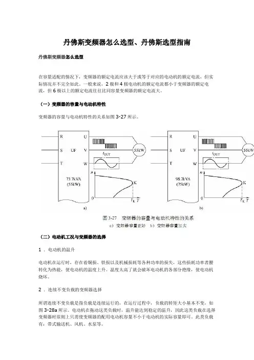
丹佛斯变频器怎么选型、丹佛斯选型指南丹佛斯变频器怎么选型在容量适配的情况下,变频器的额定电流应该大于或等于对应的电动机的额定电流,但实际情况并不完全如此。
一般来说,2极和4极电动机的额定电流都小于变频器的额定电流,但6极以上的额定电流往往比同容量变频器的额定电流大。
(一)变频器的容量与电动机特性变频器的容量与电动机特性的关系如图3-27所示。
(二)电动机工况与变频器的选择1 .电动机的温升电动机在运行时,存在着铜损、铁损以及机械损耗等各种功率的损失,这些损耗功率者腰转化为热能,使电动机的温度上升。
温度太高了就会破坏电动机的各部分绝缘,使电动机烧坏。
2 .连续不变负载的变频器选择所谓连续不变负载是指负载是连续运行的,在运行过程中,负载的转矩大小基本不变,如图3-28a所示。
电动机在拖动这类负载时,温升能达到稳定的温升,因此这类负载在选择变频器时原则上只需使变频器的配用电动机容量不小于电动机的实际容量即可。
此类负载有:带式输送机、风机、水泵等。
3 .连续变动负载的变频器选择负载是连续运行的,但负载的轻重却是经常变动的。
当电动机拖动这类负载时,其温升将随着负载转矩的轻重而变化(见图3-28b)。
选择变频器的原则是:只要电动机的温升不超过额定温升,允许短时过载。
4 .断续负载的变频器选择时开时停的负载,开的时候电动机的温升达不到稳定温升,停的时候电动机的温升也降不到O,如图3-28c所示。
对于这类负载,选择电动机容量的基本原则与连续变动负载一样。
5 .短时负载负载运行时间很短,而停止时间很长,运行时温升达不到稳定温升,停止时温升能下降为O。
如三峡水电站的船闸的闸门电动机。
这类负载在选择变频器时不考虑电动机温升,主要考虑电动机的过载能力即可。
(三)一台变频器带多台电动机1 .多台电动机同时起动和运行如果所有电动机都同时起动,并且同时升速、降速(见图3-29),变频器的容量可以按下列公式计算:即变频器的额定电流大于1.05-1.1倍的各电动机额定电流之和。
目录1. 安全性5安全说明5一般警告5开始维修工作之前6避免意外启动6变频器的安全停止6IT 主电源62. 简介9类型代码字符串103. 机械安装13开始之前13如何安装144. 电气安装21如何连接21主电源接线概述23如何连接电动机-前言27电动机接线概述28如何测试电动机和旋转方向。
325. 如何操作变频器37有三种操作方法37如何操作 NLCP37如何操作 GLCP39提示与技巧466. 如何为变频器编程49如何编程49参数列表537. 疑难解答71报警和警告71警告/报警列表738. 规范77规范77特殊条件87索引89目录 | IllustrationIllustration 2.1: 该示例显示了一个标识标志。
9Illustration 3.1: 无论机架尺寸如何,均可并排安装。
14Illustration 3.2: 请务必安装背板(A2 和 A3 除外),否则将导致冷却不充分和设备使用寿命缩短。
(如图所示) 15Illustration 3.3: 这是正确的设备安装方式。
15Illustration 3.4: 如果设备必须安装在离墙很近的位置,请定购该设备的背板(请参阅订购类型代码,第 14-15 位)。
A2 和 A3 设备标配中就带有背板。
15Illustration 3.5: 步骤 1:根据下表中的尺寸钻孔。
16Illustration 3.6: 步骤 2A:不要完全拧紧螺钉。
16Illustration 3.7: 步骤 2B:这样可以轻松地将设备挂到螺钉上。
16Illustration 3.8: 步骤 3:将设备抬起,挂到到螺钉上。
16Illustration 3.9: 完全拧紧螺钉。
17Illustration 3.10: 步骤 1:根据下表中的尺寸钻孔。
18Illustration 3.11: 步骤 2A:不要完全拧紧螺钉。
18Illustration 3.12: 步骤 2B:这样可以轻松地将设备挂到螺钉上。
目录1 如何阅读本手册3简介3安全说明5开始维修工作之前5特殊条件6避免意外启动7变频器安全停止7IT 主电源82 变风量通风系统9简介9安装11节能估计16变频器功能183 单区定风量通风系统21简介21风量控制21变频器的优势23节能25变频器功能274 冷却塔鼓风机控制29简介29鼓风机速度控制30节能31变频器功能325 冷凝器水泵送系统35简介35泵控制35变频器的优势37节能39变频器功能416 主/辅冷却水泵送系统的主泵43简介43主循环控制43节能46变频器功能497 主/辅冷却水泵送系统的辅泵51简介51循环泵控制51循环泵控制54传感器56节能57变频器功能608 变频泵送系统63简介63变速泵63传感器65节能潜力66变频器功能689 增压泵送系统71增压泵送系统71增压泵控制73选择75传感器75节能77节能79变频器功能8282索引84VLT®HVAC 变频器应用VLT®HVAC 变频器应用 1 如何阅读本手册11 1.1.1简介这些 HVAC 应用示例旨在帮助规划人员和技术人员构建具有不同功能的的 HVAC 设备。
文中介绍了 8 种典型的 HVAC 应用以及各自的节能潜力和变频器 (FC) 功能。
此外还对传统的解决方案与优化的 Danfoss VLT® HVAC 变频器解决方案进行了比较,并且介绍了后者的优势。
这些应用是:•变风量通风系统•单区定风量通风系统•冷却塔鼓风机控制•冷凝器水泵送系统•主/辅冷却水泵送系统的主泵•主/辅冷却水泵送系统的辅泵•变频泵送系统•增压泵送系统1.1.2可用文献-操作说明 MG.11.Ax.yy 提供了安装和运行该变频器所需的信息。
-设计指南 MG.11.Bx.yy 详细介绍了有关该变频器、用户设计和应用的所有技术信息。
-编程指南 MG.11.Cx.yy 提供了有关如何编程的信息,并且包括完整的参数说明。

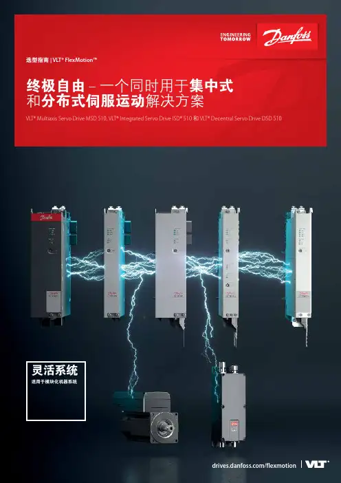
选型指南 | VLT® FlexMotion™终极自由 – 一个同时用于集中式和分布式伺服运动解决方案VLT® Multiaxis Servo Drive MSD 510, VLT® Integrated Servo Drive ISD® 510 和 VLT® Decentral Servo Drive DSD 510灵活系统适用于模块化机器系统VLT®VLT® Decentral Servo Drive DSD 510Danfoss Drives · DKDD.PB.702.A3.412 您是否正在努力对机器结构进行模块化,以适应您的业务需求?那就了解一下 Danfoss VLT® FlexMotion™ 吧。
这是一个多用途、通用型、可兼容的伺服驱动器概念,满足未来的机器结构要求而设计。
对各种模块进行组合和扩展来满足您的具体需求。
因此,其各种集中式和分布式模块让您能够实现多种功能。
开放的系统体系结构为您带来全面的自由,可选择的任何电机和 PLC 集成。
各种巧妙设计可实现快速安装和调试,从而节省时间和成本。
全部这些因素可以实现严苛环境下可靠的运行。
总而言之,该系统为您的机器设计带来终极自由度。
开放快速可靠VLT® Integrated Servo Drive ISD® 510VLT® Multiaxis Servo Drive MSD 5103Danfoss Drives · DKDD.PB.702.A3.41每个模块都让机器制造商能够保持最大灵活性,无论您需要添加新产品线 – 还是要通过增加伺服器扩展现有产品线。
4Danfoss Drives · DKDD.PB.702.A3.41使用多用途系统构建模块化机器可扩展概念现代机器系统需要在适应性和扩展方面具有极致灵活性。
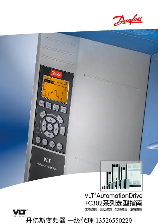
目录1. 简介32. 如何编程5本地控制面板5快捷菜单模式13功能设置19主菜单模式223. 参数说明27参数选择27主菜单 - 操作/显示 - 第 0 组28主菜单 - 负载和电动机 - 第 1 组41主菜单 - 制动 - 第 2 组52主菜单 - 参考值/加减速 - 第 3 组54主菜单 - 极限/警告 - 第 4 组61主菜单 - 数字输入/输出 - 第 5 组65主菜单 - 模拟输入/输出 - 第 6 组80主菜单 - 通讯和选件 - 第 8 组88主菜单 - Profibus - 第 9 组95主菜单 - CAN 现场总线 - 第 10 组103主菜单 - LonWorks - 第 11 组108主菜单 - 智能逻辑 - 第 13 组109主菜单 - 特殊功能 – 参数组 14118主菜单 - 变频器信息 - 第 15 组126主菜单 - 数据读数 - 第 16 组133主菜单 - 数据读数 2 - 第 18 组140主菜单 - FC 闭环 - 第 20 组142主菜单 - 扩展闭环 - FC 100 - 第 21 组152主菜单 - 应用功能 - FC 100 - 第 22 组160主菜单 - 时基功能 - FC 100 - 第 23 组173主菜单 - 变频器旁路 – 参数组 24187主菜单 - 多泵控制器 - 第 25 组193主菜单 - 模拟 I/O 选件 MCB 109 - 第 26 组2054. 疑难解答215报警和警告215报警字218警告字219扩展状态字220故障消息2215. 参数列表225参数选项225默认设置225 0-** 操作/显示226 1-** 负载/电动机228 2-** 制动229 3-** 参考值/加减速230 4-** 极限/警告231 5-** 数字输入/输出232 6-** 模拟输入/输出234 8-** 通讯和选件236 9-** Profibus238 10-** CAN 现场总线239 11-** LonWorks240 13-** 智能逻辑控制器241 14-** 特殊功能242 15-** 变频器信息243 16-** 数据读数245 18-** 信息和读数247 20-** FC 闭环248 21-** 扩展闭环249 22-** 应用功能251 23-** 基于时间的功能253 24-** 应用功能 2254 25-** 多泵控制器255 26-** 模拟输入输出选件 MCB 109257索引2591.1本设计指南适用于软件版本为 2.7x 的所有 HVAC 变频器。
机械密封选型指南每一种机械密封,只有用于规定的范围内才能有效地发挥作用。
选型不当,则会使密封性能显著降低,寿命缩短,甚至失效。
选型的主要参数如下:一、密封腔介质压力P介质润滑性好,粘度较高时,P≤0.8MPa选用非平衡型。
介质润滑性差,粘度低时,P≥0.5Mpa二、线速度VV≤25m/s选用旋转型。
V≥25m/s时选用静止型。
三、PV值PV值涉及到密封面之间流体膜的稳定性(汽化)和磨擦副的耐磨性。
PV极限值举例:四、密封介质温度T在没有外冷条件下,机械密封的最高温度一般取决于辅助密封材料的安全使用温度。
见下表:五、介质的特殊性。
1、粘度:低粘度介质易干磨擦宜选用平衡型。
高粘度介质,宜采用强制传动结构。
2、腐蚀和化学溶剂: a、强腐蚀宜用外装式的四氟波纹管密封。
b、辅助密封在不同化学介质中的适用表如下:3、含悬浮固体颗粒:动静环材料宜采用碳化钨/碳化钨,或碳化硅/碳化硅,当颗粒易于阻塞密封腔时,须采用辅助装置经过过滤或分离后的冲冼液,冲洗端面。
4、剧毒或气体介质:宜采用双端面机械密封。
泵用机械密封(一)泵用机械密封(摘自JB/T1472-1994)6.1基本型式及主要尺寸泵用机械密封共分7种基本型式,各种形式及主要尺寸见表29.7-10~13。
6.2机械密封的基本参数(见表29.7-14)表29.7-10 103型内装单端面单弹簧非平衡并圈弹簧传动机械密封B103型内装单端面单弹簧平衡型并圆弹簧传动机械密封(摘自JB/T1472-1994)(mm)注:1 安装机械密封部位的轴的轴向窜动量不大于3mm。
2 生产厂:自贡机械密封件厂、浓阳机械密封研究所、天津克半密封有限公司,到表23-20前注皆相同。
泵用机械密封(二)泵用机械密封表29.7-11 104型内装单端面单弹簧非平衡型套传动机械密封B104型内装单端面单弹簧平衡型套传动机械密封(摘自JB/T1472-1994)(mm)泵用机械密封表29.7-12 105型内装单端面多弹簧非平衡型螺钉传动机械密封B105型内装单端面多弹簧平衡型螺钉传动机械密封(摘自JB/T1472-1994)(mm)泵用机械密封表29.7-13 114型外装单端面单弹簧过平衡型拨叉传动机械密封及其派生型114a(摘自JB/T1472-1994)(mm)泵用机械密封表29.7-14基本参数①对粘度较大、润滑性好的介质取0.6~3,对粘度较小、润滑性差的介质取0.3~3。
丹佛斯变频器怎么选型、丹佛斯选型指南丹佛斯变频器怎么选型在容量适配的情况下,变频器的额定电流应该大于或等于对应的电动机的额定电流,但实际情况并不完全如此。
一般来说,2极和4极电动机的额定电流都小于变频器的额定电流,但6极以上的额定电流往往比同容量变频器的额定电流大。
(一)变频器的容量与电动机特性变频器的容量与电动机特性的关系如图3-27所示。
(二)电动机工况与变频器的选择1 .电动机的温升电动机在运行时,存在着铜损、铁损以及机械损耗等各种功率的损失,这些损耗功率者腰转化为热能,使电动机的温度上升。
温度太高了就会破坏电动机的各部分绝缘,使电动机烧坏。
2 .连续不变负载的变频器选择所谓连续不变负载是指负载是连续运行的,在运行过程中,负载的转矩大小基本不变,如图3-28a所示。
电动机在拖动这类负载时,温升能达到稳定的温升,因此这类负载在选择变频器时原则上只需使变频器的配用电动机容量不小于电动机的实际容量即可。
此类负载有:带式输送机、风机、水泵等。
3 .连续变动负载的变频器选择负载是连续运行的,但负载的轻重却是经常变动的。
当电动机拖动这类负载时,其温升将随着负载转矩的轻重而变化(见图3-28b)。
选择变频器的原则是:只要电动机的温升不超过额定温升,允许短时过载。
4 .断续负载的变频器选择时开时停的负载,开的时候电动机的温升达不到稳定温升,停的时候电动机的温升也降不到O,如图3-28c所示。
对于这类负载,选择电动机容量的基本原则与连续变动负载一样。
5 .短时负载负载运行时间很短,而停止时间很长,运行时温升达不到稳定温升,停止时温升能下降为O。
如三峡水电站的船闸的闸门电动机。
这类负载在选择变频器时不考虑电动机温升,主要考虑电动机的过载能力即可。
(三)一台变频器带多台电动机1 .多台电动机同时起动和运行如果所有电动机都同时起动,并且同时升速、降速(见图3-29),变频器的容量可以按下列公式计算:即变频器的额定电流大于1.05-1.1倍的各电动机额定电流之和。