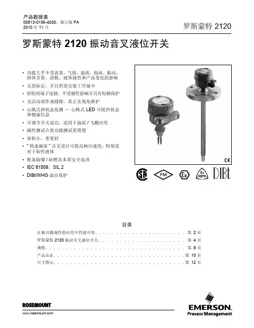
罗斯蒙特音叉开关2120
- 格式:pdf
- 大小:1.48 MB
- 文档页数:20
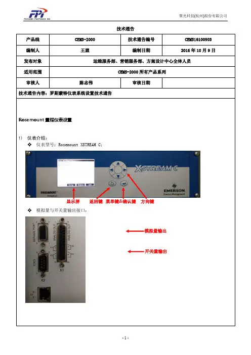
技术通告产品线 CEMS-2000 技术通告编号 CEMS16100903 编制人 王盟编制日期2016年10月9日发布对象 运维服务部、营销服务部、方案设计中心全体人员适用范围 CEMS-2000所有产品系列审核人陈志伟 审核日期技术通告内容:罗斯蒙特仪表系统设置技术通告Rosemount 量程仪表设置1) 仪表介绍:✧ 仪表型号:Rosemount XSTREAM C;✧ 模拟量与开关量输出接口:显示屏返回键 菜单键&确认键 方向键模拟量输出开关量输出✧按键说明:在测量界面按进入菜单,按为返回或取消在具体对某项设置时与是对数字位数的选择,与具有调节数字大小或者选择某个组分的功能。
仪表上电需要预热,测量主界面上的“Temperature”(温度)达到46℃左右时才算预热结束,此时才能进行调零和标定操作。
2)上电设置✧单位设置(设为ppm):(测量主界面)测量主界面按 进入菜单Control(操作)按切换到Setup(设置) 选中 Display(显示),按进入配置,选中 Unit(单位)按键来切换到ppm量程设置:测量主界面按 Control(操作),然后按切换到Setup(设置)点确定点选中In/Outputs(输入输出)点确定。
选中Analog outputs(模拟量输出)按键,选择相应的组分,因子输出顺序和测量界面因子顺序一致分别设置“LowScale”(量程下限)和“HowScale”(量程上限)按上、下键进行量程的修改,键确认更改设置,按保存。
开关量设置:测量主界面按键Control(操作) → 按切换到Setup(设置) →点选中In/Outputs(输入输出)点确定, 选中Digital outputs(数字量输出)按进行配置。
超低开关量配置:Output2(第二输出)按进行设置,按上、下键调为Fail(仪表故障) → 按保存 →Output4(第四输出)设置为AutoC(自动调零)→Output1(第一输出)和Output3(第三输出)设置为Blank(空)→ 按确认键保存常规开关量配置:Output1(第一输出)设置为Fail(仪表故障) → 按保存 →Output2(第二输出)设置为AutoC(自动调零)→Output3(第三输出)和Output4(第四输出)设置为Blank(空)→ 按确认键保存(操作方法同上) 超低仪表和常规仪表如何区分:1、开关量和模拟量开关接口(超低仪表) (常规仪表)2、自动调零时间(超低仪表) (常规仪表)自动调零时间单位不同,超低仪表单位为M;常规仪表单位为h,且不可更改。
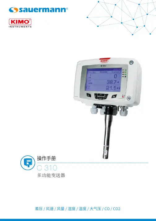
差压 / 风速 / 风量 / 湿度 / 温度 /大气压 / CO / CO2操作手册C 310多功能变送器0 / 4 ~ 20 m A - 电流输出信号接线端口 (a)电源供应 (c)电缆接入电源种类(a)模拟输出 (1)0 ~ 5 / 10 V - 电压G N D - 接地差压自动校准元件压力连接端口智能型探头连接端口差压或大气压模块差压手动零点校准以太网通讯模块总线通讯RS 485 (d)继电器 (b)N OC O MN C(b)继电器 (1)N OC O MN C继电器 (4)N OC O MN C继电器 (3)N OC O MN C继电器 (2)0 / 4 ~ 20 m A - 电流模拟输出 (4)0 ~ 5 / 10 V - 电压G N D - 接地0 / 4 ~ 20 m A- 电流模拟输出 (3)0 ~ 5 / 10 V- 电压G N D - 接地0 / 4 ~ 20 m A - 电流模拟输出 (2)0 ~ 5 / 10 V - 电压G N D - 接地(c)用于电源供应相位 中性 (c)用于电源供应相位 中性 (d)Modbus RS-485ABC 310 接线图电气接线 - 符合 NFC15-100 标准接线应由合格技术人员操作。
当接线时, 变送器必须停止供应电源。
➢电流输出信号 0 / 4 ~ 20 mA 接线方式:➢电源供应 24 Vdc 接线方式:➢电源供应 24 Vac 接线方式:➢电源供应 230 Vdc 接线方式:电源供应 24 Vac Class II显示仪 或 PLC / BMS主动种类+-24 Vdc电源供应+-N LLN Pe 230 VacLN Pe 230 Vac或LN LN LN 24 VacLN 230 Vac电源供应GND-+显示仪 或 PLC / BMS主动种类-+GNDL N 24 Vac电源供应 24 Vac Class II➢电压输出信号 0 ~ 5 / 10 V 接线方式:内容目录1. 产品介绍 (5)1.1 变送器介绍 (5)1.2 按键介绍 (5)1.3 温湿度传感器保护盖 (6)2. Modbus 通讯 (7)2.1 设置参数 (7)2.2 功能 (7)2.3 寄存器读取码 (7)3. 设置变送器 (12)3.1 输入安全码 (12)3.2 设置变送器的参数 (12)3.2.1 设置显示屏 (13)3.2.2 设置曲线图时段 (13)3.2.3 设置语言 (13)3.2.4 设置日期和时间 (13)3.2.5 开启/关闭按键音 (13)3.2.6 锁定或开启按键 (13)3.2.7 修改安全码 (14)3.2.8 恢复出厂设置 (14)3.2.9 设置Modbus通讯 (适用于已订购此功能) (14)3.2.10 设置以太网通讯 (适用于已订购此功能) (14)3.2.11 访问变送器信息 (15)3.3 设置测量通道 (15)3.4 设置模拟信号输出 (15)3.4.1 选择模拟信号输出类型 (15)3.4.2 设置模拟信号输出对应量程 (16)3.4.3 输出信号自诊断 (16)3.5 设置报警 (17)3.5.1 选择报警模式 (17)3.5.2 设置上升或下降报警模式 (18)3.5.3 设置监测报警模式 (18)3.5.4 设置变送器状态报警模式 (19)3.5.5 设置继电器 (适用于已订购此功能) (19)3.6 设置探头, 模块和标准参数 (20)3.6.1 设置风速和风量探头 (20)3.6.2 设置二氧化碳或温湿度探头 (21)3.6.3 设置模块 (21)3.7 开启其他选购功能 (24)4. 功能描述和 Modbus 通讯连接 (26)4.1 变送器 (26)4.2 测量通道 (27)4.3 输出信号 (27)4.4 报警和继电器 (28)4.4.1 报警 (28)4.4.2 继电器 (29)4.5 测量参数 (29)4.6 差压模块和探头 1 和 2 参数 (30)4.6.1 差压模块参数 (30)4.6.2 探头 1 参数 (31)4.6.3 探头 2 参数 (31)4.6.4 标准参数 (32)1. 产品介绍1.1变送器介绍C310 变送器含显示屏型号可通过按键进行设置。

Reference Manual00809-0100-4029, Rev AA July 2005Rosemount 2110Compact Vibrating Fork Liquid Level SwitchReference Manual00809-0100-4029, Rev AAJuly 2005Rosemount 2110 2110 Compact Vibrating ForkLiquid Level SwitchRead this manual before working with the product. For personal and system safety, and for optimum product performance, make sure you thoroughly understand the contents before installing, using, or maintaining this product.The United States has two toll-free assistance numbers and one International number. Customer Central1-800-999-9307 (7:00 a.m. to 7:00 P.M. CST)International1-(952) 906-8888National Response Center1-800-654-7768 (24 hours a day)Equipment service needsThe products described in this document are NOT designed for nuclear-qualified applications. Using non-nuclear qualified products in applications that require nuclear-qualified hardware or products may cause inaccurate readings.For information on Emerson Process Management nuclear-qualified products, contact your local Emerson Process Management Sales Representative.Rosemount pursues a policy of continuous development and product improvement. The specification in this document may therefore be changed without notice. To the best of our knowledge, the information contained in this document is accurate and Rosemount cannot be held responsible for any errors, omissions or other misinformation contained herein. No part of this document may be photocopied or reproduced without the prior written consent of Rosemount.Reference Manual00809-0100-4029, Rev AA Rosemount 2110July 2005Reference Manual00809-0100-4029, Rev AAJuly 2005Rosemount 2110 Table of ContentsSECTION 1IntroductionSwitch Overview . . . . . . . . . . . . . . . . . . . . . . . . . . . . . . . . . . . . . . . . . . . . . . . . . . . . . . . .1-2 Short Fork Technology. . . . . . . . . . . . . . . . . . . . . . . . . . . . . . . . . . . . . . . . . . . . . . . .1-2 Rosemount 2110 Application and Mounting Examples. . . . . . . . . . . . . . . . . . . . . . . . . . .1-2 Overfill Protection. . . . . . . . . . . . . . . . . . . . . . . . . . . . . . . . . . . . . . . . . . . . . . . . .1-3Pump Protection. . . . . . . . . . . . . . . . . . . . . . . . . . . . . . . . . . . . . . . . . . . . . . . . . .1-3High and Low Level Alarm. . . . . . . . . . . . . . . . . . . . . . . . . . . . . . . . . . . . . . . . . .1-3Leak Detection. . . . . . . . . . . . . . . . . . . . . . . . . . . . . . . . . . . . . . . . . . . . . . . . . . .1-3Pump Control. . . . . . . . . . . . . . . . . . . . . . . . . . . . . . . . . . . . . . . . . . . . . . . . . . . .1-3Hygienic Applications. . . . . . . . . . . . . . . . . . . . . . . . . . . . . . . . . . . . . . . . . . . . . .1-3 Application Considerations . . . . . . . . . . . . . . . . . . . . . . . . . . . . . . . . . . . . . . . . . . . . . . . .1-4 Handling the 2110. . . . . . . . . . . . . . . . . . . . . . . . . . . . . . . . . . . . . . . . . . . . . . . . . . . . . . .1-4 Rosemount Identification. . . . . . . . . . . . . . . . . . . . . . . . . . . . . . . . . . . . . . . . . . . . . . . . . .1-6 Installation Considerations and Recommendations . . . . . . . . . . . . . . . . . . . . . . . . . . . . .1-7 Switchpoint. . . . . . . . . . . . . . . . . . . . . . . . . . . . . . . . . . . . . . . . . . . . . . . . . . . . . . . . .1-8 Service Support. . . . . . . . . . . . . . . . . . . . . . . . . . . . . . . . . . . . . . . . . . . . . . . . . . . . . . . . .1-9 Warranty. . . . . . . . . . . . . . . . . . . . . . . . . . . . . . . . . . . . . . . . . . . . . . . . . . . . . . . . . . .1-9 SECTION 2InstallationSafety Messages. . . . . . . . . . . . . . . . . . . . . . . . . . . . . . . . . . . . . . . . . . . . . . . . . . . . . . . .2-1 Mechanical Installation . . . . . . . . . . . . . . . . . . . . . . . . . . . . . . . . . . . . . . . . . . . . . . . . . . .2-1 Correct Fork Alignment. . . . . . . . . . . . . . . . . . . . . . . . . . . . . . . . . . . . . . . . . . . . . . . . . . .2-2 Pipe Installation . . . . . . . . . . . . . . . . . . . . . . . . . . . . . . . . . . . . . . . . . . . . . . . . . . . . .2-2 Vessel Installation. . . . . . . . . . . . . . . . . . . . . . . . . . . . . . . . . . . . . . . . . . . . . . . . . . . .2-2 Cover Orientation . . . . . . . . . . . . . . . . . . . . . . . . . . . . . . . . . . . . . . . . . . . . . . . . . . . .2-3 Electrical Installation . . . . . . . . . . . . . . . . . . . . . . . . . . . . . . . . . . . . . . . . . . . . . . . . . . . . .2-4 Mode Selection. . . . . . . . . . . . . . . . . . . . . . . . . . . . . . . . . . . . . . . . . . . . . . . . . . . . . .2-4 LED Indication . . . . . . . . . . . . . . . . . . . . . . . . . . . . . . . . . . . . . . . . . . . . . . . . . . . . . .2-5 Function . . . . . . . . . . . . . . . . . . . . . . . . . . . . . . . . . . . . . . . . . . . . . . . . . . . . . . . . . . .2-6 Wiring . . . . . . . . . . . . . . . . . . . . . . . . . . . . . . . . . . . . . . . . . . . . . . . . . . . . . . . . . . . . .2-7 Reference Manual00809-0100-4029, Rev AA July 2005Rosemount 2110TOC-2SECTION 3Troubleshooting Magnetic Test Point. . . . . . . . . . . . . . . . . . . . . . . . . . . . . . . . . . . . . . . . . . . . . . . . . . . . . .3-1Inspection . . . . . . . . . . . . . . . . . . . . . . . . . . . . . . . . . . . . . . . . . . . . . . . . . . . . . . . . . . . . .3-1Maintenance . . . . . . . . . . . . . . . . . . . . . . . . . . . . . . . . . . . . . . . . . . . . . . . . . . . . . . . . . . .3-2Troubleshooting. . . . . . . . . . . . . . . . . . . . . . . . . . . . . . . . . . . . . . . . . . . . . . . . . . . . . . . . .3-2Spare Parts. . . . . . . . . . . . . . . . . . . . . . . . . . . . . . . . . . . . . . . . . . . . . . . . . . . . . . . . . . . .3-2APPENDIX AReference DataPhysical Specifications . . . . . . . . . . . . . . . . . . . . . . . . . . . . . . . . . . . . . . . . . . . . . . . . . . A-1Mechanical . . . . . . . . . . . . . . . . . . . . . . . . . . . . . . . . . . . . . . . . . . . . . . . . . . . . . . . . A-1Performance Specifications. . . . . . . . . . . . . . . . . . . . . . . . . . . . . . . . . . . . . . . . . . . . . . . A-2Functional Specifications. . . . . . . . . . . . . . . . . . . . . . . . . . . . . . . . . . . . . . . . . . . . . . . . . A-2Electrical. . . . . . . . . . . . . . . . . . . . . . . . . . . . . . . . . . . . . . . . . . . . . . . . . . . . . . . . . . A-3Dimensional Drawing . . . . . . . . . . . . . . . . . . . . . . . . . . . . . . . . . . . . . . . . . . . . . . . . . . . A-5Ordering Information. . . . . . . . . . . . . . . . . . . . . . . . . . . . . . . . . . . . . . . . . . . . . . . . . . . . A-6Accessories . . . . . . . . . . . . . . . . . . . . . . . . . . . . . . . . . . . . . . . . . . . . . . . . . . . . . . . . . . A-7APPENDIX BProduct CertificationsL.V. Directive. . . . . . . . . . . . . . . . . . . . . . . . . . . . . . . . . . . . . . . . . . . . . . . . . . . . . . . . . . B-1Electro Magnetic Compatibility (EMC) Directive . . . . . . . . . . . . . . . . . . . . . . . . . . . . . . . B-1Overfill Protection . . . . . . . . . . . . . . . . . . . . . . . . . . . . . . . . . . . . . . . . . . . . . . . . . . . . . . B-1Approved Manufacturing Locations. . . . . . . . . . . . . . . . . . . . . . . . . . . . . . . . . . . . . . . . . B-1Reference Manual00809-0100-4029, Rev AAJuly 2005Rosemount 2110S ECTION 1I NTRODUCTIONSwitch Overview . . . . . . . . . . . . . . . . . . . . . . . . . . . . . . . . . . . . . . . . . . . . . page 1-2Rosemount 2110 Application and Mounting Examples . . . . . . . . . . . . . page 1-2Application Considerations . . . . . . . . . . . . . . . . . . . . . . . . . . . . . . . . . . . . page 1-4Handling the 2110 . . . . . . . . . . . . . . . . . . . . . . . . . . . . . . . . . . . . . . . . . . . . page 1-4Installation Considerations and Recommendations . . . . . . . . . . . . . . . . page 1-7Rosemount Identification . . . . . . . . . . . . . . . . . . . . . . . . . . . . . . . . . . . . . page 1-6Service Support . . . . . . . . . . . . . . . . . . . . . . . . . . . . . . . . . . . . . . . . . . . . . page 1-9Procedures and instructions in this manual may require special precautions to ensure the issues is indicated by a caution symbol (Reference Manual00809-0100-4029, Rev AAJuly 2005Rosemount 21101-2The Rosemount 2110 is a liquid point level switch based on the vibrating short forktechnology. It is a compact switch with a rugged stainless steel body and forks for use in a wide range of liquid applications. Economical 3/4-in. or 1-in. threaded mounting in pipes or tanks or hygienic mounting for food industry use. Direct load switching suits all supplies or PNP output for direct interface to PLCs. For use in safe area only.Short Fork TechnologyThe natural frequency (~1300Hz) of the fork is chosen to avoid interference from plant vibration which may cause false switching. This also gives short fork length for minimal intrusion into vessel and pipe. Using Short Fork Technology, the Rosemount 2110 isdesigned for use in virtually all liquid applications. Extensive research has maximized the operational effectiveness of the fork design making it suitable for almost all liquids, including coating liquids (avoid bridging of forks), aerated liquids, and slurries.Rosemount 2110 Application and Mounting ExamplesFor most liquids including coating and aerated liquids and slurries, the function is virtually unaffected by flow, turbulence, bubbles, foam, vibration, solid particles, build-up or properties of the liquid.For use in safe area and process temperatures up to 302°F (150°C).Mount in any position in the tank or pipe. Mounting is by 3/4-in. or 1-in. threaded or hygienic fitting.2110c l e a r _r e v .t i fReference Manual00809-0100-4029, Rev AAJuly 2005Rosemount 21101-3Overfill ProtectionSpillage caused by overfilling can be hazardous to people and theenvironment, resulting in lost product, and clean up costs. The 2110 is alimit level switch used to signal overfill at any time.Pump ProtectionShort forks mean minimum intrusion wetside and allow simple low costinstallation at any angle into your pipes or vessels. With the fork projectingonly 2-in. (50 mm) (dependant on connection type), the 2110 can beinstalled in even small diameter pipes. By selecting the option of direct loadswitching electronics, the 2110 is ideal for reliable pump control and can beused to protect against pumps running dry.High and Low Level AlarmMaximum and minimum level detection in tanks containing many differenttypes of liquids are an ideal application for the 2110. The robust 2110operates continuously at temperatures up to 302°F (150°C) and operatingpressure up to 1450 psig (100 barg) making it perfect for use as a high orlow level alarm. It is common practice to fit an independent high level alarmswitch to provide extra back up to the level switch in case of failure.Leak DetectionFlanges, gaskets, seals, corrosive liquids – they all have the potential toleak at the most inconvenient times. Many users site tanks and vesselsabove trays or in containments to prevent any liquids from escaping. Alevel switch can quickly and accurately detect any leakage and therebyeliminating cost.Pump ControlMany processes have batching and header tanks, and there is usually theneed to control a pump to maintain levels between set points. These tanksare often manufactured from thin wall materials and cannot support theweight of heavy instrumentation.Hygienic ApplicationsWith the option of highly polished forks providing a surface finish (Ra)better than 0.8 µm, the 2110 meets the principle design criteria of the moststringent hygienic requirements used in food and beverage, andpharmaceutical applications. Manufactured in stainless steel the 2110 isrobust enough to easily withstand steam cleaning (CIP) routines attemperatures up to 302°F (150°C).Reference Manual00809-0100-4029, Rev AA July 2005Rosemount 21101-4Application Considerations •Ensure liquid is inside the temperature and pressure ranges (see specifications).•Check that the liquid is inside recommended viscosity range 0.2 to 10,000 cP .•Examples of products with too high of viscosity is chocolate syrup, ketchup, peanut butter and bitumen. The switch will still detect these products but the drain time can be very long.•Check that the liquid density is above 37.5 lb/ft 3 (600 kg/m 3).•Examples of products with too low of density is acetone, pentane and hexane. •Check for risk of build-up on the forks.•Avoid situations where drying and coating products may create excessive build-up.•Ensure no risk of bridging the forks.•Examples of products that can create bridging of forks are dense paper slurries and bitumen.•Check if solid content in liquid•Problems may occur if product coats and dries causing caking•As a guideline maximum solid particle diameter in the liquid is 0.2-in. (5 mm)•Extra consideration is needed when dealing with particles bigger than 0.2-in. (5 mm), consult factoryHandling the 2110Figure 1-1. Do not hold the 2110 by forks.2110/2110_19a a , 2110_19a a .e p s1-5Figure 1-2. Do not alter the 2110 in any way.2110/2110_27a a .e p s1-6Rosemount IdentificationFigure 1-3. Load Switching Models: ac/dcFigure 1-4. PNP solid state output Models: dc low voltage: 21...264V AC (50/60Hz) /DC 2110/2110_57a a , 2110_58a a .e p s1-7Installation Considerations and RecommendationsBefore you install the Rosemount 2110 Level Switch, consider specific installation recommendations and mounting requirements.•Install in any orientation in tank containing liquid.•Always install in the normally “on” state•For high level recommendation is Dry = on (see “Function” on page 2-6).•For low level recommendation is Wet = on (see “Function” on page 2-6).•Always ensure the system is tested by using the local magnetic test point during commissioning (see “Magnetic Test Point” on page 3-1).•Ensure sufficient room for mounting and electrical connection (see “Dimensional Drawing” on page A-5).•Ensure that the forks do not come into contact with the tank wall or any internal fittings or obstructions.•Ensure the forks does not come into contact with the tank wall of any internal fitting.•Avoid installing the 2110 where it will be exposed to liquid entering the tank at the fill point.•Avoid heavy splashing on fork •Avoid product buildup•Ensure no risk of bridging the forks.•Ensure there is sufficient distance between build-up on the tank wall and the fork.•Ensure installation does not create tank crevices around the forks where liquid may connect (important in high viscosity and high density liquids).•Extra consideration is needed if the plant vibration is close to the 1300 Hz operating frequency of the 2110.•Ensure sufficient clearance for the fork so highly viscous liquids quickly flow off the forks.•Extra consideration is needed if the plant vibration is close to the 1300 Hz operating frequency of the 2110.Figure 1-5. Example of OK and not OK build-up on tank wall.2110/2110_25a a , 2110_26a a .e p s1-8Switchpoint2120/f i g 12.e p sSwitchpoint (H 20) (SP)Switching hysteresis (HY)In the top diagram a lowerdensity media will give switchpoint closer to the connection. A higher density media will give switchpointcloser to fork tip.Service SupportTo expedite the return process outside of the United States, contact the nearest Rosemount representative.Within the United States, call the Rosemount National Response Center using the1-800-654-RSMT (7768) toll-free number. This center, available 24 hours a day, will assist you with any needed information or materials.The center will ask for product model and serial numbers, and will provide a Return Material Authorization (RMA) number. The center will also ask for the process material to which the product was last exposed.Rosemount National Response Center representatives will explain the additional information and procedures necessary to return goods exposed to hazardous substance can avoid injury if they are informed of and understand the hazard. If the product being returned was exposed to a hazardous substance as defined by OSHA, a copy of the required Material Safety Data Sheet (MSDS) for each hazardous substance identified must be included with the returned goods.WarrantyEmerson Process Management will replace a faulty or failed 2110 with a new unit provided that the fault or failure is reported either directly or via an accredited representative, within 1 year from the date of supply, and the product has been installed and used in accordance with Emerson Process Management instruction manual 00809-0100-4029. Emerson Process Management reserves the right to examine such product and to refuse replacement at its discretion if the above conditions are not met.1-91-10S ECTION 2I NSTALLATIONSafety Messages . . . . . . . . . . . . . . . . . . . . . . . . . . . . . . . . . . . . . . . . . . . . page 2-1Mechanical Installation . . . . . . . . . . . . . . . . . . . . . . . . . . . . . . . . . . . . . . . page 2-1Correct Fork Alignment . . . . . . . . . . . . . . . . . . . . . . . . . . . . . . . . . . . . . . . page 2-2Electrical Installation . . . . . . . . . . . . . . . . . . . . . . . . . . . . . . . . . . . . . . . . . page 2-4Safety MessagesProcedures and instructions in this manual may require special precautions to ensure the issues is indicated by a caution symbol (). The external hot surface symbol (Mechanical InstallationFigure 2-1. SealingFigure 2-2. Tighten the SwitchGasketBSPP (G1)NPT, BSPT (R)Seal (supplied in 02100-1020-0001)Tri-ClampPTFE (Teflon)2110/2110_28a a , 2110_29a a .e p s2-2Correct Fork AlignmentEnsure correct fork alignment.Pipe InstallationVessel Installation2110/14a a .e p sAlignment groove2110/24a a , 2110_16a a .e p s2110/2110_34a a .t i f2-3Cover Orientation2110/2110_36a a .e p sElectrical Installation Mode SelectionMode Selection by customer wiring.2-4Reference Manual00809-0100-4029, Rev AAJuly 2005Rosemount 2110 LED Indication2-5Reference Manual00809-0100-4029, Rev AAJuly 2005Rosemount 21102-6FunctionPLC (positive output)PNP dcLoad switching ac/dcLEDU <100uAU <100uAReference Manual00809-0100-4029, Rev AA July 2005Rosemount 21102-7WiringThe 2110 is IP66 and IP67 when correctly assembled with the supplied connector and suitable cable.NOTEUse only connector supplied.1.Insert cable into plug housing and connect to terminals.2.Ensure both seals are in place to maintain the weatherproof rating.3.Fit plug to body.Maximum 0.31 (8)Minimum 0.24 (6)5.9 (1.5)2110/2110_15a a .e p s2110/ 2110_15a b .e p s Screw SealPlug Seal2110/ 2110_28a c .e p sReference Manual00809-0100-4029, Rev AAJuly 2005Rosemount 21102-84.Tighten the screw.5.Plug fitted.RELAY CONNECTION WARNING (FOR DIRECT LOAD SWITCHING)The Rosemount 2110 requires a minimum current of 3mA, which continues to flow when the 2110 is ‘off’. If selecting a relay to wire in series with the 2110, the user must ensure that the drop-out voltage of the relay is greater than the voltage which will be generated across the relay coil when 3mA flows through it.NOTE (FOR DIRECT LOAD SWITCHING)DPST = ‘Double Pole, Single Throw’ (on/off) switch - must be fitted for safe disconnection of the power supply. Fit the switch as near to the 2110 as possible. Keep the switch free of obstructions. Label the switch to indicate that it is the supply disconnection device for the 2110.2110/ 2110_28a b .e p sPlug Fitted2110/2110_17a a .e p sReference Manual00809-0100-4029, Rev AA July 2005Rosemount 2110S ECTION 3T ROUBLESHOOTINGMagnetic Test Point . . . . . . . . . . . . . . . . . . . . . . . . . . . . . . . . . . . . . . . . . . page 3-1Inspection . . . . . . . . . . . . . . . . . . . . . . . . . . . . . . . . . . . . . . . . . . . . . . . . . . page 3-1Maintenance . . . . . . . . . . . . . . . . . . . . . . . . . . . . . . . . . . . . . . . . . . . . . . . . page 3-2Troubleshooting . . . . . . . . . . . . . . . . . . . . . . . . . . . . . . . . . . . . . . . . . . . . . page 3-2Spare Parts . . . . . . . . . . . . . . . . . . . . . . . . . . . . . . . . . . . . . . . . . . . . . . . . . page 3-2Magnetic Test PointA magnetic test point is marked on the side of the housing allowing a functional test of the 2110. By touching a magnet on the target the 2110 output will change state for as long as the magnet is present.InspectionVisually examine the 2120 for damage. If it is damaged, do not use. Check connector and seals are correctly fitted, also that the connector fixing screw and gland are tight.Ensure the LED flash rate is 1 Hz or continually on. If anything else is demonstrated see “LED Indication” on page 2-5.2110/2110_47a a .e p sNormal Condition Test ConditionNo MagnetMagnetReference Manual00809-0100-4029, Rev AAJuly 2005Rosemount 21103-2MaintenanceNOTEIf using a brush to clean, ensure it is of a soft type.TroubleshootingIf there is a malfunction, see Table 3-1 for information on possible causes.Table 3-1. Troubleshooting chart.Spare PartsSee “Accessories” on page A-7.Symptom/Indication Action/SolutionDoes not switch•No LED; no power•Check the power supply; (checkload on direct load switching electronics model)•LED 3 flashes per second •Internal failure; contact supplier •LED 1 flash every 2 seconds •Uncalibrated; return to supplier •LED 1 flash every 4 seconds•Load fault; load current too high, load short circuit; check installation •Fork damaged•Replace•Thick encrustation on forks•Clean the fork with care • 5 second delay on changing mode/delay•Wait 5 secondsIncorrect switching•Dry = On, Wet = On set correctly•Check wiring in the connector. See “Mode Selection” on page 2-4Faulty switching•Excessive electrical noise•Suppress the cause of the interference2110_07a a , 2110_20a a , 2110_12a aReference Manual00809-0100-4029, Rev AAJuly 2005Rosemount 2110 A PPENDIX A R EFERENCE D ATAPhysical Specifications . . . . . . . . . . . . . . . . . . . . . . . . . . . . . . . . . . . . . . . page A-1 Performance Specifications . . . . . . . . . . . . . . . . . . . . . . . . . . . . . . . . . . . page A-2 Functional Specifications . . . . . . . . . . . . . . . . . . . . . . . . . . . . . . . . . . . . . page A-2 Dimensional Drawing . . . . . . . . . . . . . . . . . . . . . . . . . . . . . . . . . . . . . . . . . page A-5 Ordering Information . . . . . . . . . . . . . . . . . . . . . . . . . . . . . . . . . . . . . . . . . page A-6 Accessories . . . . . . . . . . . . . . . . . . . . . . . . . . . . . . . . . . . . . . . . . . . . . . . . page A-7 Physical SpecificationsProductRosemount 2110 Compact Liquid Level SwitchMeasuring principleVibrating ForkApplicationsMost liquids including coating liquids, aerated liquids, and slurriesMechanicalProcess material316L Stainless Steel (1.4404)For Tri-Clamp connection hand polished to better than 0.8 μm. Gasket material for 1 in. BSPP (G1) is Non-asbestos BS7531 Grade X carbon fiber with rubber binder.Housing materialsBody: 304 SST with polyester labelLED window: Flame retardant Polyamide (Pa12) UL94 V2Plug: Polyamide glass reinforcedPlug seals: Nitrile butadiene rubber 122-in. (50 mm)ConnectionsSee “Process Connection Size / Type” on page A-6.Mounting•3/4-in. BSPT (R) or NPT•1-in. BSPT (R) or BSPP (G) thread, or•Hygienic 2-in. (51 mm) Tri-clamp fittingDimensional DrawingsSee “Dimensional Drawing” on page A-5Ingress of Protection RatingIP66/67 to EN60529Reference Manual00809-0100-4029, Rev AAJuly 2005Rosemount 2110A-2Performance SpecificationsHysteresis (water)±0.039-in. (± 1mm) nom.Switching point (water)0.5-in. (13mm) from tip (vertical) / from edge (horizontal) of fork (this will vary with different liquid densities)Functional SpecificationsMaximum Operating PressureFinal rating depends on tank connectionThreaded Connection See Figure A-1.Hygienic Connection 435 psig (30 barg)Figure A-1. Process PressureTemperature See Figure A-2.Figure A-2. Temperature(-40)(50)(150)Process Temperature °F (°C)P r o c e s s P r e s s u r e p s i g (b a r g )2120/2120_18a b .e p s (0)(60)(-40)(150)Process Temperature °F (°C)A m b i e n t T e m p e r a t u r e °F (°C )2120/2120_18a c .e p s(0)Reference Manual00809-0100-4029, Rev AAJuly 2005Rosemount 2110 Liquid DensityMinimum 37.5 lb/ft3 (600 kg/m3)Liquid Viscosity Range0.2 to 10,000 cP (centiPoise)Solids Content and CoatingMaximum recommended diameter of solid particles in the liquid is 0.2-in. (5 mm).For coating product, avoid bridging of forks.Switching delay1 sec dry to wet/wet to dryCIP (Clean In Place) CleaningWithstands steam cleaning routines up to 302°F (150°C)ElectricalSwitching modeUser selectable (Dry =on or Wet =on) by selecting plug wiringCable connectionVia 4-way plug provided - DIN43650. Max. conductor size - 15AWG. Orientation 4-position(90/180/270/360 deg).Conductor sizeMaximum 0.06 inch2 (1.5 mm2)Cable glandPG9 provided - cable diameter 0.24 to 0.31-in. (6 to 8 mm)ProtectionReverse polarity insensitive. Missing load / short circuit protectionGroundingThe 2110 should always be grounded either through the terminals or using the external ground connection provided.A-3Reference Manual00809-0100-4029, Rev AAJuly 2005Rosemount 2110A-4Operating Voltage21 to 264V ac (50-60Hz)/dc Maximum switched load 500mAMaximum peak load 5A for 40 ms max.Minimum switched load 20mA continuousVoltage drop6.5V @ 24V dc / 5.0V @ 240V ac Current draw (load off)<3.0mA continuousOperating Voltage18-60V dc Maximum switched load 500mAMaximum peak load 5A for 40 ms max.Voltage drop <3VSupply Current3mA nominal Output current (load off)<0.5mALoad0V/N+V/N PEReference Manual00809-0100-4029, Rev AAJuly 2005Rosemount 2110 Dimensional DrawingTable A-1. Dimensions are in inches (millimeters)Connections A B C D3/4-in. BSPT (R) 2.72 (69) 1.97 (50)7.40 (188)N/A 3/4-in. NPT 2.72 (69) 1.97 (50)7.40 (188)N/A1-in. BSPT (R) 2.72 (69) 1.97 (50)7.40 (188)N/A1-in. BSPP (G) 3.07 (78) 2.36 (60)7.91 (201)N/A 2-in. (51 mm) Tri-Clamp 2.72 (69) 1.97 (50)7.40 (188) 2.52 (64)1-in. Semi-extended 4.57 (116) 3.86 (98)9.41 (239)N/AA-5Reference Manual00809-0100-4029, Rev AA July 2005Rosemount 2110A-6Ordering Information2110Compact Vibrating Fork Liquid Level Switch 0Direct load switching with plug connection (2 wire) 21 to 264 V ac 50/60 Hz, 21 to 264 V dc 1PNP/PLC low voltage switching with plug connection 18 to 60 V dc 0A3/4-in. BSPT (R) thread 1A1-in. BSPT (R) thread 0D3/4-in. NPT thread 2R 2-in. (51mm) Tri-clamp 1B1-in. BSPP (G) thread 1L1-in. BSPP (G) Semi-extended 4.6-in. (116 mm)NANo Hazardous Locations Certifications (safe area use only)Overfill U1DIBt/WHG Overfill protection Calibration Data Certificate Q4Certificate of functional test Tag Plates STTag plate SST engraved plate (maximum 16 digits)WT Tag plate laminated paper (maximum 40 digits)。
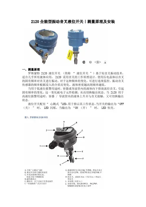
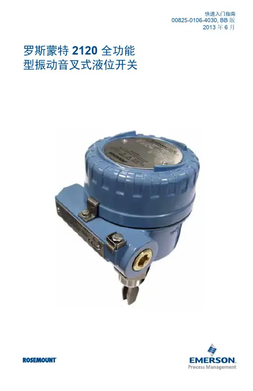
2120全能型振动音叉液位开关|测量原理及安装一、测量原理罗斯蒙特 2120 液位开关(简称“液位开关”)基于短音叉振动技术,适合几乎所有液体应用, 2120 采用音叉的工作原理设计。
使用压电晶体以音叉的固有频率对音叉进行振动。
对于这种频率的变化,可进行连续监控。
振动音叉传感器的频率根据浸入的介质而变化。
液体密度越高则频率越低。
当用于低液位报警用途时,容器或导波管内的液体向下排放流经音叉,引起固有频率的变化,这一变化被电子元件检测,从而切换输出状态。
当 2120 用于高液位报警用途时,容器 / 导波管内的液体上升并与音叉接触,又可切换输出状态。
液位开关配有“心跳式”LED,用于指示其工作状态。
当开关的输出为“OFF (关)”时, LED 闪烁,当输出为“ON (开)”时, LED 恒亮。
二、安装准备工作该液位开关可提供本安或防爆 / 防火型。
还可提供适用于普通场所的液位开关型(针对未分类的安全区域)和卫生型。
带重型法兰和延长型音叉的罗斯蒙特 2120 液位开关(简称“液位开关”)的重量可能超过 18 kg (37 lb)。
搬运、吊装和安装液位开关前需要进行风险评估。
对罗斯蒙特 2120 应轻拿轻放,请采用正确姿势。
如下图:环镜考虑因素:此液位开关设计为在开放式或封闭式储罐以及管道上安装。
它不受天气影响,能够防尘,但必须防止其受到水淹。
确保在储罐或管道外有足够的空间。
需要 30 mm (1.2 in.) 空隙,以便拆卸护盖。
务必安装金属外壳盖,使金属与金属接触,或塑料与塑料接触,从而确保正确密封。
应使用罗斯蒙特 O 形圈。
必须按照国家和当地电气规范将外壳接地。
最有效的接地方法是直接接地来获得最小阻抗。
对于带有 NPT 导管入口的金属外壳,应使用音叉的地线。
三、安装建议*避免安装在储罐进液口附近。
*避免音叉溅上大量液体。
应增加延时以减少意外开关情况。
*避免安装在热源附近。
*确保音叉不与罐壁 / 管壁或配件接触。
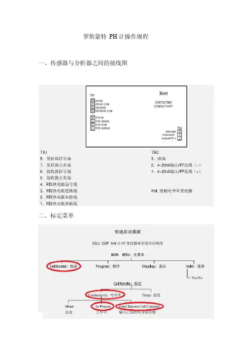
罗斯蒙特PH计操作规程一、传感器与分析器之间的接线图二、标定菜单三、准备工具:电导率标液、大活扳手一把、抹布若干、水杯一个四、标定过程:电导率的标定我们采用的标定方法类似于单点标定。
首先我们应该将电导率探头取出用蒸馏水或者新鲜水清洗干净。
要是有杂质粘附或者堵塞在探头的检测缝隙内就要用相应的试剂进行清除(或者用其他办法但是必须确保电极的完好)。
清洗完成后要用吸水纸或者干净的抹布将探头尽量的擦拭干净以免杂质(水或者其他电解质)融入试剂中影响标液的试值从而影响标定结果。
清理完后此时需要标定电导率零点,电导率零点的标定很简单就是将探头置于空气中看电导率会不会归零要是不归零就可以用一下方法进行标定按MENU键→进入主菜单→再选中calibrate→进入标定菜单→再选中标定项conductivty→然后选中in process进入标定状态。
此时界面显示上方为测量值,下面为标定值。
此时在下方Cal 的位置输入0然后按ENTER键即可做完这些这些之后就可以开始标定量程了,将探头放进试剂中,此时最好电极是悬浮于标液中不要让电极碰到容器四壁,标液最好高于电极10mm左右以保证电极完全侵没在标液之中,完成这些就可以进行第的标定了。
按MENU键→进入主菜单→再选中calibrate→进入标定菜单→再选中标定项conductivty→然后选中in process进入标定状态。
此时界面显示上方为测量值,下面为标定值。
然后输入此时标准液的真实值例如:147待测量值稳定后就可以按确认键,在此过程中可以轻微的摇晃探头使得电极与标液充分接触,但是小心不能损坏电极,洒落标液或者使电极暴漏于空气中。
此时如果检测示值与真实值偏差过大并且长时间恢复不过来应检查电导池常数(因为一般情况下一旦投用电导池常数是正确的)。
按MENU键→进入主菜单→再选中calibrate→进入标定菜单→再选中标定项conductivty→按右键选中》在按ENTER进入之后选中resistivity进入看里面的数值是否跟要求的(或者名牌上)的电导池常数一致。

快速安装指南00825-0106-4030, Rev GB2022 年 3 月Rosemount™ 2120 液位开关振动音叉快速安装指南2022 年 3 月内容关于本指南 (3)安装 (5)准备电气连接件 (11)接线和通电 (26)组态 (30)操作 (32)2Rosemount 2120 液位开关2022 年 3 月快速安装指南1关于本指南本快速安装指南提供 Rosemount2120的基本安装指导。
更多说明,请参阅Rosemount 2120参考手册。
手册和本指南的电子版本亦可以从/Rosemount获得。
1.1安全信息警告不遵守安全安装与检修准则,可能导致死亡或严重受伤。
请确保由取得相关资质人员按照相应的操作规程安装物位开关。
只能使用本手册中规定的物位开关。
只能使用本手册中规定的物位开关。
带重型法兰和延长型音叉的物位开关的重量可能超过 37 lb. (18 kg)。
搬运、吊装和安装物位开关前必须执行风险评估。
修理设备(例如更换组件等)可能危害安全性,在任何情况下都是不允许的。
警告爆炸可能会导致死亡或严重受伤。
验证物位开关的工作环境符合相应的危险场所认证。
在易爆气体环境中,连接手持通讯器之前,请确保按照本质安全或非易燃现场接线实践安装仪表。
在隔爆以及非易燃型安装中,不得在液位开关通电的情况下拆卸壳体盖子。
为满足隔爆要求,壳体盖子必须完全盖上。
警告触电可能导致死亡或严重受伤。
不得接触引线或接线端子。
引线上可能存在的高压会导致触电。
在进行物位开关接线时,请确保物位开关的电源处于关闭状态,并且与任何其他外部电源连接的线路均处于断开状态,或者没有通电。
确保接线符合电流要求,且绝缘符合电压、温度和环境要求。
快速安装指南3快速安装指南2022 年 3 月警告过程泄漏可能导致死亡或严重受伤。
请务必轻拿轻放物位开关。
如果过程密封件受损,气体可能会从容器(储罐)或管道中逸出。
警告物理接触未经授权的人员可能会对最终用户的设备造成明显受损和/或误组态。
罗斯蒙特-EHSMALL—MRO工业品LAB实验室设备M我司为(美国ROSEMOUNT罗斯蒙特)代理,价格优惠,欢迎来电咨询。
福州长浩自动化设备有限公司汪其淼0591-********134********QQ:86727437/86047030罗斯蒙特压力变送器(工控仪表) 1151AP4E12M1B202罗斯蒙特测长传感器(传感器) 1151DP4S22M1B4L4P1S2罗斯蒙特测长传感器(传感器) 1151DP4S22B1M1DFL4罗斯蒙特测长传感器(传感器) 1151DP4S22S2M1B3E3罗斯蒙特压力变送器(工控仪表) 1151AP5S52B3M1罗斯蒙特压力变送器(工控仪表) 1151DP5S22S2M1B3E3罗斯蒙特接近开关(传感器) 1151DP4S52B1M1DF 0-37.3KPa罗斯蒙特压力变送器(工控仪表)1151DP5S22B3M4K5S2罗斯蒙特压力变送器(工控仪表) 1151GP0S52B3M1罗斯蒙特压力变送器(工控仪表) 1151DP5S22B5Q4M4P1罗斯蒙特压力变送器(工控仪表) 1151GP4S22M4B3C5罗斯蒙特测长传感器(传感器) 1151G P7S22S1M1B3E3罗斯蒙特接近开关(传感器) 1151HP5S52B3M1 罗斯蒙特测长传感器(传感器) 1151GP6S 22B3M1 DF 1/2NPT罗斯蒙特压力变送器(工控仪表) 1151LT5SA0T22DM1DFE3罗斯蒙特测长传感器(传感器) 1151GP9S52B3M1罗斯蒙特压力变送器(工控仪表) 1199DDC56DFFWJGDA00罗斯蒙特压力变送器(工控仪表) 1151LT4SA0T22DM1DFE3罗斯蒙特压力变送器(工控仪表) 1151LT6SE0T22DM1DFE3罗斯蒙特测长传感器(传感器) 1151GP6S22B3M4K5D2DF罗斯蒙特测长传感器(传感器) 375HR1ENA9罗斯蒙特压力变送器(工控仪表) 3051TG3A2B21AB4罗斯蒙特压力变送器(工控仪表) 3051TG1A2B21AS1B4E5M5罗斯蒙特测长传感器(传感器) 1199DHE59AFFW71DC00罗斯蒙特压力变送器(工控仪表) 3051TG2A2B21AB4罗斯蒙特接近开关(传感器) 1199PDC59AFFWG1DC00罗斯蒙特压力变送器(工控仪表) 1199WDC56AFFWG5DA00CV罗斯蒙特压力变送器(工控仪表) 1199DDC59AFFWG1DA00CV罗斯蒙特压力变送器(工控仪表) 1199DDC53DFFWJGDA000罗斯蒙特测长传感器(传感器) 1199DDC62DEFWJGDD60罗斯蒙特测长传感器(传感器)1199DDC60DFFWJGDC00罗斯蒙特压力变送器(工控仪表) 01151-0137-0001(智能型)罗斯蒙特压力变送器(工控仪表) 3051SFADG200ZCHFS2A1C003AAA1罗斯蒙特压力变送器(工控仪表) 1199WDC56AFFWG5DA00罗斯蒙特测长传感器(传感器) 1199DDC63DFFWJGDC00罗斯蒙特压力变送器(工控仪表) 3051TG2A2B21AB415M5罗斯蒙特压力变送器(工控仪表) 208862SA1M5 罗斯蒙特压力变送器(工控仪表) 3051SFADG140ZCHFS2A1C0031AA1罗斯蒙特测长传感器(传感器) 3051S2CD4A2A 罗斯蒙特压力变送器(工控仪表) 3051TG2A2B21AB4M5罗斯蒙特压力变送器(工控仪表) 0065D21D0035D0300T44E5罗斯蒙特压力变送器(工控仪表) 0065D21D0035D0300T44E5罗斯蒙特压力变送器(工控仪表)3051L2AJOYH21AAE5M5罗斯蒙特压力变送器(工控仪表) 3051CG4A22A1AB4E5M5 0~0.6MPA罗斯蒙特接近开关(传感器) 3051TG3A2B21AB4E5M5Q4罗斯蒙特压力变送器(工控仪表) 3051L3AAOTA21AAQ4罗斯蒙特压力变送器(工控仪表) 3051CD2A22A1BM5B4K5DF罗斯蒙特压力变送器(工控仪表) 3051TG4F2A21AB4I5M5 0~25mpa罗斯蒙特压力变送器(工控仪表) 1199WHF56AFFWG1DC000罗斯蒙特压力变送器(工控仪表) 3051CD1A22A1AM5B4DFI5 0~0.004mpa罗斯蒙特测长传感器(传感器) 3051TG1A2B21BB4M5罗斯蒙特接近开关(传感器) 375-F-R-1-E-NA-U 罗斯蒙特测长传感器(传感器) 3051S2C02A2E 罗斯蒙特测长传感器(传感器) 3051S2CD4A2A11A1AP0罗斯蒙特压力变送器(工控仪表)罗斯蒙特专用传感器(传感器) 0301RC32B11B4 罗斯蒙特压力变送器(工控仪表) 3051TG4A2B21AB4M5S1罗斯蒙特压力变送器(工控仪表) 3051CD3A22A2BS5B4E8M6罗斯蒙特压力变送器(工控仪表) 3051L3AA0TD21ACM5罗斯蒙特测长传感器(传感器) 3051CD2A22A1AB4罗斯蒙特压力变送器(工控仪表) 0054PH/ORP 罗斯蒙特压力变送器(工控仪表) 3051CG5A52A1AB4I5M5 0~4mpa罗斯蒙特压力变送器(工控仪表) 3051CD2A22A2BS5B4E8罗斯蒙特压力变送器(工控仪表) 3051CG4A22A1AM5B4DFI5 0~0.6mpa罗斯蒙特压力变送器(工控仪表) 3051L2AA2TD21ACL4Q4罗斯蒙特测长传感器(传感器) 3051TG3A2B21K罗斯蒙特压力变送器(工控仪表)罗斯蒙特压力变送器(工控仪表) 1151DP4S22B1DFM1罗斯蒙特压力变送器(工控仪表) 3051CG4A22A1AB4E5M5 0~1.6MPA罗斯蒙特压力变送器(工控仪表) 3051CD2A22A1AS2M5B4E5罗斯蒙特液位变送器(工控仪表) RTG3940/THE罗斯蒙特测长传感器(传感器) 3051CG5A22A1AB4E5M5 0~6MPA罗斯蒙特压力变送器(工控仪表) 3051TA1A2B21BB4M5罗斯蒙特测长传感器(传感器) 3051S2LD3AA1A1020DFF71DC00M5罗斯蒙特接近开关(传感器) 3051CG4A22A1AM5B4DFI5 0~1.0mpa罗斯蒙特塑壳断路器(低压断路器) NS100/3P/80A 29631罗斯蒙特压力变送器(工控仪表) 3051CD3A22A1AB4罗斯蒙特测长传感器(传感器)3051TG3A2B21CB4M5罗斯蒙特压力变送器(工控仪表) 3051CG3A22A1AB4DF 0-100KPA罗斯蒙特压力变送器(工控仪表) 644HAE5J6M5罗斯蒙特压力变送器(工控仪表) 3051CG3A22A1AB4E5M5 0~0.2MPA罗斯蒙特压力变送器(工控仪表) 3051TG5A2B31AB4M5 0-60MPA罗斯蒙特测长传感器(传感器) 3051TG2A2A21KE5罗斯蒙特压力变送器(工控仪表) 3051TG4A2B21CB4M5罗斯蒙特测长传感器(传感器) 3051CG4A52A1AB4I5M5 0~1mpa罗斯蒙特压力变送器(工控仪表) 3051CD1A02A1AS5B4M5 0301RC32B11罗斯蒙特塑壳断路器(低压断路器) NS400N/3P/380V 32693罗斯蒙特专用传感器(传感器) 3051CD3A22A1AM5B4罗斯蒙特测长传感器(传感器)3051CG5A52A1AB4I5M5 0~10mpa罗斯蒙特压力变送器(工控仪表) 3051CD3A22A1AS2M5B4E5罗斯蒙特压力变送器(工控仪表) 3051CD1A22A1BM5B4K5DF罗斯蒙特测长传感器(传感器) 3051CG2A22A1AM5B4DFI5 0~0.03mpa罗斯蒙特压力变送器(工控仪表) 01151-0137-0001(模拟量型)罗斯蒙特压力变送器(工控仪表) 3051GP3A2B21AB4M5 0-1MPA罗斯蒙特压力变送器(工控仪表) 3051CD3A22A1AM5B4DFI5 0~0.2mpa罗斯蒙特塑壳断路器(低压断路器) NS100N-100A-3P 29630罗斯蒙特接近开关(传感器) 3051CD2A22A1AM5B4DFI5 0~0.03mpa罗斯蒙特阀门执行器(电和气动驱动器) 0306RT22BA11罗斯蒙特测长传感器(传感器) 3051CG5A22A1AB4E5M5 0~4MPA罗斯蒙特压力变送器(工控仪表)3051TG1A2B21AB4M5S1罗斯蒙特测长传感器(传感器) 2090PG2S22C3M5罗斯蒙特测长传感器(传感器) 1151DP3S22B2 罗斯蒙特压力变送器(工控仪表) 3051TA1A2B21AS5B4M5 0306RT22BA11罗斯蒙特测长传感器(传感器) 3051CG1A22A1AM5B4DFI5 0~0.004mpa罗斯蒙特压力变送器(工控仪表) 3051CD2A02A1AB4M5S5 0305RC32B11罗斯蒙特专用传感器(传感器) 01199-0018-1111 罗斯蒙特断路器附件(低压断路器) DZ10-100/330罗斯蒙特转换器(工业以太网) 54EPH-ORP-01-09罗斯蒙特压力变送器(工控仪表) 1151G8S52B3M1罗斯蒙特压力变送器(工控仪表) 3051TG1A2B21AS5B4M5 0306RT22AA11罗斯蒙特压力变送器(工控仪表) 3051CD1A22A1AB4DF 0-6KPA罗斯蒙特压力变送器(工控仪表)3051TG4A2B21AS5B4M5 0306RT22BA11罗斯蒙特真空开关(真空设备) NS160H/160A/3P(30670)罗斯蒙特专用传感器(传感器) 2088G3S22D2 0~55.2BAR罗斯蒙特真空开关(真空设备) NS100N IN=100A/380V(29630)罗斯蒙特液位变送器(工控仪表) RTG39ABRS00R01罗斯蒙特压力变送器(工控仪表) 3051CD0A02A1BH2L4M5B3罗斯蒙特专用传感器(传感器) 2088G2S22D2 0~10.3BAR罗斯蒙特压力变送器(工控仪表) 3051CD1A02A1AS5M5 0301RC32B11B4罗斯蒙特压力变送器(工控仪表) 2088G2S22A2 罗斯蒙特压力变送器(工控仪表) 3051CD3A22A1AB4DF罗斯蒙特便携式四合一气体检测仪(工控仪表) TETRA罗斯蒙特压力变送器(工控仪表) 3051TG1A2B21AB4M5罗斯蒙特压力变送器(工控仪表) 3051CG2A02A1AS5M5 0305RT22A11B2罗斯蒙特压力变送器(工控仪表) 3051TG4A2B21AS5B4M5 0306RT22AA11罗斯蒙特压力变送器(工控仪表) 3051TG3A2B21AS5B4E5M5 0306RT22BA罗斯蒙特压力变送器(工控仪表) 3051CG2A02A1AS5M5 0305RT22A11B1罗斯蒙特压力变送器(工控仪表) 3051TG2A2B21AS5B4M5 0306RT22AA11罗斯蒙特便携式一氧化碳检测仪(工控仪表) GASMAN-III 0-500PPM罗斯蒙特压力变送器(工控仪表) 3051CD3A02A1AS5M5 0301RC32B11B4罗斯蒙特压力变送器(工控仪表) 3051GP3A2B21AB4M5E5 0-1MPA罗斯蒙特压力变送器(工控仪表) 3051CG3A02A1AS5M5 0305RT22A11B2罗斯蒙特压力变送器(工控仪表) 3051CG2A02A1AB4M5S5 0305RC22B11罗斯蒙特低压熔断器(熔断器) BR1-40A罗斯蒙特压力变送器(工控仪表)罗斯蒙特专用传感器(传感器) 3051L3AA07D21ACM5罗斯蒙特压力变送器(工控仪表) 3051CD2A02A1AB4M5S5 0305RC22B11罗斯蒙特压力变送器(工控仪表) 2088G2S22A2 0-0.8MPA罗斯蒙特便携式硫化氢检测仪(工控仪表) GASMAN-III 0-50PPM罗斯蒙特数据采集卡(工控机) DAU\2100罗斯蒙特行程开关(传感器) LX510-12-380V 10A罗斯蒙特时间继电器(继电器) \JQX\10F罗斯蒙特压力变送器(工控仪表) 2090PA2S22A3E5罗斯蒙特转换开关(低压配电开关) LW5-16B0020/1罗斯蒙特压力变送器(工控仪表) 3051CG3A02A1AS5M5 0305RT22A11B1罗斯蒙特压力变送器(工控仪表) 305CD3A22B1KS5B4M6罗斯蒙特压力变送器(工控仪表)罗斯蒙特压力变送器(工控仪表) 3051CD4A02A1AS5E5M5 0301RC32B11B罗斯蒙特压力变送器(工控仪表) 3051CD3A22A1AS2B4E8Q41199WDB54DRFWDGDAA5 1199MDC6罗斯蒙特落地式配电柜(机柜系列) RITTAL罗斯蒙特压力变送器(工控仪表) 3051CD2A22A1AS2B4E8Q4-1199WDB58DRF WDGAA5罗斯蒙特压力变送器(工控仪表) 3051TG1A2B21A罗斯蒙特压力变送器(工控仪表) 3051TG3A2B21AB4 0-1.6MPA罗斯蒙特压力变送器(工控仪表) 3051TG3A2B21AS5B4M5 0306RT22AA11罗斯蒙特压力变送器(工控仪表) ROSEMOUNT罗斯蒙特压力变送器(工控仪表) 3051CG4A2B21AB4K5DF 0-1.6MPA罗斯蒙特压力变送器(工控仪表)3051TG4A2B21AB4 0-6MPA罗斯蒙特压力变送器(工控仪表) 3051CD3A22A1BM5B4DF罗斯蒙特压力变送器(工控仪表) 1151DP6S22B3D2AY1 0-0.25MPA罗斯蒙特熔芯(熔断器) RSF-AC500/750A-BCK100KA罗斯蒙特测长传感器(传感器) 3051CD2A02A1AM5S5罗斯蒙特压力变送器(工控仪表) 3051CD3A02A1AS5B4M5 0301RC32B11罗斯蒙特压力变送器(工控仪表) 3051TG2A2B21AS5B4E5M5 0306RT22BA罗斯蒙特压力变送器(工控仪表) 3051L2AAOTD21ACL4M5罗斯蒙特压力变送器(工控仪表) 3051TG1A2B21AS5B4M5 0306RT22BA11罗斯蒙特压力变送器(工控仪表) 3051CG2A22A1A罗斯蒙特压力变送器(工控仪表) 3051L4AA4TD11ACL5罗斯蒙特压力变送器(工控仪表)罗斯蒙特压力变送器(工控仪表) 3051CD3A22A1AS2B4E8Q4-1199WDB54DRFWDGDAA5罗斯蒙特压力变送器(工控仪表) 3051CG2A22A1BB4DF罗斯蒙特压力变送器(工控仪表) 3051CD2A23A1BM5B4DF罗斯蒙特压力变送器(工控仪表) 1151DP4S22B1D1AY1 0-10KPA罗斯蒙特便携式氢气检测仪(工控仪表) GASMAN-III 0-100%LEL罗斯蒙特压力变送器(工控仪表) 1151DP4S22B1D1AY1 0-30KPA罗斯蒙特压力变送器(工控仪表) 3051CG4A02A1CH2L4M5罗斯蒙特压力变送器(工控仪表) 3051CD3A02A1CH2L4M5罗斯蒙特压力变送器(工控仪表) 3051CG2A22A1A 0-20KPA罗斯蒙特压力变送器(工控仪表)罗斯蒙特压力变送器(工控仪表) 3051TG2A2B21AB4 0-1MPA罗斯蒙特压力变送器(工控仪表) 3051TG2A2B21AB4 0-0.6MPA罗斯蒙特压力变送器(工控仪表) 3051CD0A02A1AB3DFH2L4 -50PA-50PA罗斯蒙特压力变送器(工控仪表) 3051TG4A2B21AB4 0-10MPA罗斯蒙特压力变送器(工控仪表) 3051TG4A2B21AB4 0-16MPA罗斯蒙特压力变送器(工控仪表) 1151DP5S22B1D1AY1 0-100KPA罗斯蒙特稳压电源(工业电源) WYJ-12V2A罗斯蒙特压力变送器(工控仪表) 3051TG4A2B21AB4罗斯蒙特压力变送器(工控仪表) 3051TG1A2B21AB4 0-0.1MPA罗斯蒙特压力变送器(工控仪表) 3051TG2A2B31BB4M5罗斯蒙特压力变送器(工控仪表) 1151DP7S22B2罗斯蒙特压力变送器(工控仪表) 1151DP4S22B3D1AY1 0-30KPA罗斯蒙特压力变送器(工控仪表) 1151DP6S22B1D1AY1 0-625KPA罗斯蒙特压力变送器(工控仪表) 1151DP5S22B1D2AY1 0-100KPA罗斯蒙特限位开关(传感器) 73-1356N-B2罗斯蒙特调压阀(阀) 0305RC32B11罗斯蒙特压力变送器(工控仪表) 3051CG5A22A1AM5B4DFE5罗斯蒙特压力变送器(工控仪表) 3051CG3A22A1AE54Q罗斯蒙特直流电压表(电压表) PMAC600B-Z-CS罗斯蒙特压力变送器(工控仪表) 1151DP4S22B1D1AY1 -18-0KPA罗斯蒙特压力变送器(工控仪表) 1151DP4S22B1D1AY1 0-18KPA罗斯蒙特流量开关(阀) 456-060-181 480V AC 5A罗斯蒙特熔断器底座(熔断器) 10×38罗斯蒙特压力变送器(工控仪表)3051CD2A22A1BB4E5M5S2(配2个1199DDC64APFWG2DA00)罗斯蒙特压力变送器(工控仪表) 3051CD4A07A1BS5E5M5膜片:镀金(配0301RC32B11B4L40)罗斯蒙特压力变送器(工控仪表) 3051CG4A22A1BB4E5M5S1(配1199WDC59APCWG2DA00)罗斯蒙特压力变送器(工控仪表) 3051CD2A02A1DS5I5M5(配0301RC32B11B4L4)罗斯蒙特压力变送器(工控仪表) 3051CG4A22A1BB4E5L4M5DF罗斯蒙特压力变送器(工控仪表) 3051CG3A22A1DB4I5L4M5DF罗斯蒙特压力变送器(工控仪表) 3051CD4A02A1BS5E5M5(配0301RC32B11B4L4)罗斯蒙特压力变送器(工控仪表)3051CD2A22A1BB4E5M5S2(配2个1199DDC66APFWG2DA00)罗斯蒙特压力变送器(工控仪表) 3051CG5A22A1DB4I5L4M5DF罗斯蒙特压力变送器(工控仪表) 3051CG3A22A1BB4E5L4M5DF罗斯蒙特压力变送器(工控仪表) 3051CD2A22A1BB4E5M5S2(配2个1199DDC69APFWG2DA00)罗斯蒙特压力变送器(工控仪表) 3051CD3A02A1BS5E5M5罗斯蒙特压力变送器(工控仪表) 3051CG4A22A1DB4I5L4M5DF罗斯蒙特压力变送器(工控仪表) 3051CG5A22A1BB4E5L4M5DF罗斯蒙特压力变送器(工控仪表) 3051CG5A27A1BB4E5L4M5DF膜片:镀金罗斯蒙特压力变送器(工控仪表) 3051CG5A22A1BB4E5M5S1(配1个1199WDC59APCWG4DA00)罗斯蒙特压力变送器(工控仪表) 3051CD2A02A1BS5E5M5(0301RC32B11B4L4)罗斯蒙特直流电压表(电压表) JSGW-0.5 380/100V罗斯蒙特直流电压表(电压表) DTSD720罗斯蒙特压力变送器(工控仪表) 3051CD1A22A1AB4DF罗斯蒙特压力变送器(工控仪表) 3051CD4A22A1AB4DF罗斯蒙特压力变送器(工控仪表) 3051CD2A22A1AB4DF罗斯蒙特压力变送器(工控仪表) 3051GP3A2B21AB4M5罗斯蒙特压力变送器(工控仪表) 3051TG3A2B21A罗斯蒙特压力变送器(工控仪表) 3051CD2A22A1AB4 0-5KPA罗斯蒙特压力变送器(工控仪表) 3051CG2A22A1AB4 -6~0KPA罗斯蒙特压力变送器(工控仪表) 3051TG1A2B21C 0-20KPA罗斯蒙特压力变送器(工控仪表) 3051TG2A2B21C 0-1MPA罗斯蒙特压力变送器(工控仪表) 3051CG2A22A1CB4 0-12KPA罗斯蒙特压力变送器(工控仪表) 3051CG2A22A1CB4 -4~0KPA罗斯蒙特压力变送器(工控仪表) 3051TG1A2B21C 0-80KPA罗斯蒙特电子变压器(变压器) 3051CG2A22A1AM5B4DF罗斯蒙特压力变送器(工控仪表) 3051GP2A2B21AB4M5D1罗斯蒙特压力变送器(工控仪表) 3051TG2A2B21A罗斯蒙特断路器附件(低压断路器) 375FRIEKLU罗斯蒙特压力变送器(工控仪表) 3051TG2A2B21BB4罗斯蒙特压力变送器(工控仪表) 3051L2AG0MD11AA罗斯蒙特压力变送器(工控仪表) 2088G1S22A1 罗斯蒙特压力变送器(工控仪表)1199WDAB3AFFWG1CA000罗斯蒙特压力变送器(工控仪表) 3051CG4A22A1AM5B4DF。
舟山世纪太平洋化工工程创亚太一流自动化控制基地舟山世纪太平洋化工有限公司舟山世纪太平洋化工工程创亚太一流自动化控制基地舟山世纪太平洋化工库区由南京扬子设计院设计,并对库区所有罐区、码头输配系统的自动控制系统采用以计算机为核心的数据采集和监控系统,油库的计算机控制系统采用分散式的数据采集、控制,集中监视和管理的方式。
控制中心完成对油库的数据采集、数据处理及存储归档、控制、故障处理、安全保护、报警等任务,同时完成罐区管理、罐区液位计量、流量计贸易交接计量、装船油泵运行状态、仪表故障诊断及分析等功能。
控制中心的调度和操作人员通过操作员工作站提供的油库储罐和库内管道的压力、温度、流量、密度、设备运行状态等信息对全库区进行监控及运行管理。
先进、高度集成的储罐自控系统,结合其他安全监控系统和信息管理系统,形成高精度的贸易交接、先进的控制水平、可靠的安全保障、全面、迅速、便捷的信息反应体系。
一:SCADA系统(组态自控系统):我们一期工程选用施耐德电气公司Modicon TSX Quantum大型PLC,分别在中央控制机房、现场机柜间、1#码头机柜间、2#码头机柜间设置1#、2#、3#、4#控制站。
为充分保证设备安全可靠,本系统采用冗余光纤双环网充分保证系统的安全平稳运行,热备系统采用双底板双CPU的热备系统,提供包括CPU、电源和通讯的热备方案,在故障时实现主站到后备站的自动无扰切换,主站和后备站之间采用光纤连接交换数据,保证系统稳定、可靠、高速。
本项目在系统结构设计上,采用符合工业设计规范要求的设备层、控制层和信息层的分层结构模式,在系统设备层中,主要监测和控制的设备参数为:储油罐液位、温度、压力的变化;油泵运行状态;气动蝶阀开关状态、电动消防阀门状态、可燃气体浓度检测和油料计量设备。
与英格索兰空压机采用标准Modbus RS485协议通讯;与氮压机采用PROFIBUS-DP协议通讯。
在软硬件系统的配置和设计上,为将来系统工程扩建以及今后的技术改造预留接口。