mms33(GE微量水分析仪说明书)
- 格式:pdf
- 大小:3.17 MB
- 文档页数:80
4.USER INTERFACE 用户界面Controller Display 控制显示器The 5000 Controller default normal operation screen is shown in Figure 4-1. The first three lines of the display are fully user-programmable. Live moisture concentration and system values such as cell temperature, pressure, and flow rate can be displayed. The fourth line displays system messages and alarm / error information only. Refer to Display Flags and Labels in Chapter 5 for more information on changing the format of the controller display. 5000控制器默认的通常操作界面如图4-1所示。
显示屏前三行用户是可完全设计(编程)的。
实时潮湿度和系统数值,比如单元温度,压力,流动速度都可以显示出来。
第四行只显示系统信息和警报/错误信息。
关于控制显示器变换格式的更多信息请参照第5章控制显示器显示标记和标签。
Figure 4-1. Typical operation screen (system message will vary) 典型操作界面(系统信息不同)System Security and Passwords 系统的安全性和密码The 5000 Controller has four system security levels: Levels 0, 1, 2 and Level 3.You must enter a password before you can access certain menus and system values. Factory default passwords are listed later in this section.5000控制器有四层系统安全性:0,1,2层和3层。
HTYWS-H微量水分测定仪HTYWS-H微量水分测定仪菜单及按键操作说明仪器按键为无标识按键,在不同的显示界面下,按键具有不同的功能,由对应显示的菜单来决定,这样的设计减少了按键数量,按键功能定义明确,使得人机界面更加友好。
由于采用了大屏幕液晶,每屏画面所能显示的信息量更丰富,减少了切换显示画面的数量,用户学习使用仪器变得更简单。
仪器共分为5个显示画面:1、开机欢迎画面;2、时间调整画面;3、历史记录画面;4、样品测定画面;5、测定结果画面。
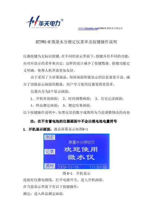
以下按键操作说明中,加黑反显的数字或图形为当前调整修改的内容注:在不含蓄电池的仪器画面中不会出现电池电量符号1. 开机显示画面:液晶屏幕显示如图6-1图6-1 开机显示连接好仪器电源线,打开电源开关,进入开机画面。
在当前显示界面下有以下按键操作:测定:进入样品测定画面。
HTYWS-H微量水分测定仪记录:进入历史记录查看画面。
调时:进入时间调整画面。
2. 时间调整显示画面:液晶屏幕显示如图6-2图 6-2 时间调整调整内容分为:“年,月,日,时,分,秒”在当前显示界面下有以下按键操作:跳格:光标在各数字项移动。
增加:光标处的数字加1,长时间按下该键,数字快速增加。
减少:光标处的数字减1,长时间按下该键,数字快速减少。
对时:更新当前的日期与时间。
将调整后的日期、时间写入仪器。
退出:退出时间调整画面,回到开机欢迎画面3. 历史记录显示画面:液晶屏幕显示如图6-3图6-3 历史记录 HTYWS-H微量水分测定仪在当前显示界面下有以下按键操作:前页:显示前一条历史记录,记录号减1,长时间按下该键,快速向前翻页,最大记录号为255。
后页:显示后一条历史记录,记录号加1,长时间按下该键,快速向后翻页,最小记录号为0。
删除:删除当前的记录,显示下一条记录。
打印:打印当前的历史记录,打印内容包括:样品编号、含水量、含水率、检测日期、检测时间。
退出:退出历史记录画面,回到开机欢迎画面。
GSM-03型精密微水仪使用说明书扬州市福来特桥架电气制造厂目录一、前言二、水份测量的重要性三、国内微水(湿度)测量方法概述四、测量原理五、主要技术参数六、操作方法七、按键说明八、注意事项九、售后服务附录:1.六氟化硫断路器含水量测量要求一、前言本公司经过多年对微水仪的开发与销售,并经仔细的市场调研,针对GSMO-03型露点仪的一些不足之处,我公司在GSM0-03型的基础上又开发了GSM-03型智能精密露点仪,主要特点如下:1、将原来的畜电池改用了能量密度大、体积小、重量轻的锂离子电池。
对充电、自动关断的全自动电源管理方式,即使用户不打开电源开关,只要插上220V交流电源可自动充电。
当电池量充到一定程度时,系统会自动判断并将其切断。
这样有效地阻止了电对电池的过充电,在使用过程中,仪器会检测电池电量的减少(显示在第二屏),但当电池电量为10%时仪器会提示用户进行充电,当电池电量不足5%时仪器会自动关机。
有效地防止了对电池的过放电,以避免对电池的损坏。
2、根据市场调研的情况来看,内置微型打印机的意义并不大,因为它最多能将测试资料打印出来,并不便于永久的保存,GSM精密露点仪一方面为了减小体积,另一方面也为减轻整机重量,使用户便于携带、便于使用,我们取消了内置微型打印机。
3、GSM-03型机保存记录以后,用户没有办法记住那条记录是测得哪个设备,针对这种情况,我们在开发GSM智能露点仪时,对每个记录,都加了设备名称一栏,即用户在保存记录时,需要输入设备名称,在以后调显时,可以根据设备名称来查相应的记录。
注意:设备名称总共六位,每位可以是0-9这10个阿拉伯数,用户可以通过上下键来修改每一位,左右移动键来确定每位。
4、针对电力系统对压力这个参数比较重视,所以GSM智能露点仪提高了压力测量的精度(±0.05Mpa)和分辩率(0.001Mpa),响应速度也更快。
本仪器主要是针对H2、SF6等无污染性气体的微水(露点)测量而开发的,在开发的过程中始终以“一切为了方便用户”为宗旨。
在线水分仪是指一种对固体、液体及浆体物料中水分含量进行在线测量的仪器。
在线水分仪又叫在线水分测量仪、在线水分测定仪、在线水分检测仪、在线水分分析仪、在线测水仪等,与常见的实验室水分仪、便携式水分仪不同,在线水分仪的最大优势在于可以实现对水分含量的在线实时测量,有效解决了传统测量方式的存在诸多弊端,同时满足各行业对水分含量的测量工作需求。
水分含量测量,是各行业产品生产和交易中的一个不可忽视的重要环节,而传统水分含量测量的方法,已经无法满足市场需求。
随着在线水分仪技术成熟和应用,极大解决了水分含量实时在线测量的难题。
目前,主流的在线水分仪主要有德国默斯进口在线微波水分仪和在线近红外水分仪等两种,可以实现卡车、皮带、烘干机、搅拌机、烧结机、料斗、储料仓、管道、螺旋输送机、溜槽、矿槽等不同工况下对物料进行实时水分含量动态连续测量,不仅可以降低人工成本,减少企业经营成本,更重要的是提高了原料水分含量的测量精度,为生产和交易提供准确的数据。
近年来,德国默斯进口在线近红外水分仪和在线微波水分仪的市场需求量越来越大,被普遍广泛应用于冶金、煤炭、化工、石油、造纸业、烟草、建材、糖业、食品、粮食、制药、日化、饲料、阿胶等各行业中的原料在线水分检测、生产过程在线水分检测及产品质量在线控制。
一、公司简介默斯测控技术(深圳)有限公司是德国默斯技术有限公司设在中国的办事处,成立于2012年,是一家专业提供德国默斯在线水分仪产品的销售和技术服务的高新技术企业。
德国默斯技术有限公司(MOSYE TECH GMBH)成立于1994年,总部位于慕尼黑普科姆工业园区,长期致力于固体、液体、浆体物料含水率测量技术的研究和应用,特别注重技术创新和新技术应用。
目前,德国默斯已经开发出多套适合各种工况的在线水分测量解决方案,是全球专业的水分测量解决方案提供商。
德国默斯在线水分仪产品系列及技术方案,广泛应用于粮食、饲料、建材、煤炭、制药、食品、糖业、日化、造纸、烟草、冶金、石油、阿胶、纺织、电力、化工等各行业原料水分检测、生产过程水分检测,以及产品质量控制等工艺环节。
WS―3型微量水分测定仪使用说明书上海高致精密仪器有限公司第一章概述WS―3型微量水分测定仪是库仑仪和卡尔―菲休法有效结合的应用电量法测定微量水分的新型仪器。
该仪器采用了大电解电流及电流自动控制,测定结果直接数字显示,具有测定速度快,分析过程时间短、精度高、操作简单,从而成为高效率、全自动的水分测定仪器。
主要用于石油、化工、医药、农药、炸药、纺织品、颜料、油漆、矿物原料等物质中水分的测定。
第二章技术参数显示系统;五位十进制数字读出单位;微克水电解电流;0―400毫安自动控制测定范围;0.1微克―100%灵敏阈;0.1微克精确度;10微克―1毫克水±5微克;大于1毫克水±0.5%电源;220V 50HZ功率消耗;30VA使用环境温度;5℃―40℃使用环境湿度;≤80%外形尺寸;330mm×260mm×150mm.重量;7千克第三章工作原理卡尔―菲休同水的反应式为;I2+SO2+3C5H5N+H2O―→2C5H5N•HI+C5H5N•SO3……⑴C5H5N•SO3+CH3OH―→C5H5N•HSO4CH3………………⑵在卡尔―菲休库仑滴定法中,把样品加入到试剂当中,在阳极上由电解所产生的碘与样品中的水起反应。
根据法拉第定律,同电荷量成正比例关系。
如下式;2Iˉ―2e―I2………⑶由(1)式可以看出,参加碘的克分子数等于水的克分子数。
把样品注入试剂中,样品中的水即参加反应,通过仪器可反映出反应过程中碘的消耗量,经仪器计算,在数字显示器上直接显示出测定的水分含量。
该仪器采用电解电流自动控制系统,电解电流的大小可根据样品中的含水量进行自动选择,最大300毫安,在电解过程中,水分逐渐减少,电解电流也随之按比例减小,直到相应的电解终点控制回路开启。
这一系统保证了分析过程中的高精度、高灵敏度和高速度。
另外,在做试验过程当中,难免会有一些干扰因素,如从空气中侵入的水分,使电解池吸潮,而产生空白电流。

SC-3微量水分测定仪操作规程一、开机准备工作:1、打开包装箱,如图安装好仪器。
2、将电极头两根铂丝平行分开,一端插入五口反应瓶电极接口处,另一端的插头插入电极插座。
3、用乳胶管连接五口反应瓶和滴定管,并在乳胶管中放入一个玻璃珠。
4、在小干燥管塞上开一个孔,插入滴定管,并在小干燥管内装入干燥剂。
5、关闭五口反应瓶上放排液进气口的玻璃阀门。
(如果需要将五口反应瓶中的液体排出,应打开排液进气口的玻璃阀门,堵住瓶上余下跑气口,用双链球加压将五口反应瓶中的液体排出。
6、在贮液瓶中倒入适量卡尔·费休试剂。
7、加入无水甲醇(分析纯于反应瓶中,至淹没电极铂丝即可。
8、用一手压住滴定管上的气孔,另一手用双链球加压,将卡尔·费休试剂缓缓地由贮液瓶压入滴定管的满刻度(零位后松手。
9、接通电源,打开电源,指示灯亮。
将选择开关置于“校正”位置,旋转“校正”旋钮,使电流表调到满度(50μA,然后将选择开关置于“测量”位置。
10、适当调节搅拌旋钮,使反应瓶中的液体在搅拌的作用下旋转。
二、测量方法:1、滴定甲醇的水份:(确定终点用手按动滴定管上的滴定玻璃珠,用卡尔·费休试剂滴定甲醇中的水份,此时电流表指示数值开始上升,随着卡尔·费休液不断滴入,电流表指示数值会逐步增大,反应瓶中的液体颜色也会由浅色转为棕色,当电流表接见45μA~48μA处,并基本不变,即可认为此值为滴定终点值。
2、标定卡尔·费休试剂:用双链球加压使卡尔·费休试剂到达滴定管的满刻度。
再用10微升微型注射器取10ul蒸馏水(G-标准水,通过加料入口橡皮盖中注入反应瓶中(不要将水溅到瓶壁,从而影响测量精度,这时反应瓶中原有棕色即可变为淡黄色,同时电流表数会由大变小直至最小。
这时,应进行滴定,随着卡尔·费休液不断滴入,电流表指示数值会逐步增大,反应瓶中的液体颜色也会产生变化,当电流表到达终点值且基本不变,即可认为此值为滴定终点值。
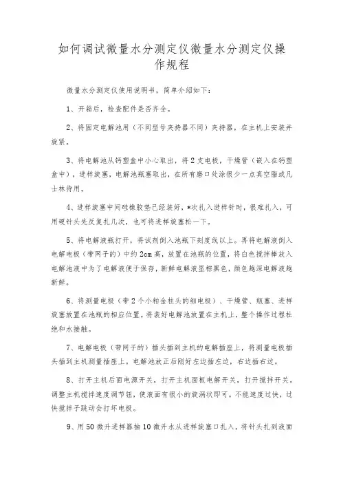
如何调试微量水分测定仪微量水分测定仪操作规程微量水分测定仪使用说明书,简单介绍如下:1、开箱后,检查配件是否齐全。
2、将固定电解池用(不同型号夹持器不同)夹持器,在主机上安装并旋紧。
3、将电解池从钙塑盒中小心取出,将2支电极,干燥管(嵌入在钙塑盒中),进样旋塞,电解池瓶塞取出,在所有磨口处涂很少一点真空脂或凡士林待用。
4、进样旋塞中间硅橡胶垫已经装好,*次扎入进样针时,很难扎入,可用硬针头先反复扎几次,也可将进样旋塞松一下。
5、将电解液瓶打开,将试剂倒入池瓶下刻度线以上。
再将电解液倒入电解电极(带网子的)中约2cm高,放置在池瓶的位置,将白色搅拌棒放入电解池液中为了电解液便于保存,新鲜电解液显棕黑色,颜色越深电解液越新鲜。
6、将测量电极(带2个小粕金柱头的细电极)、干燥管、瓶塞、进样旋塞放置在池瓶的相应位置。
将装好电解池放置在主机上,整个操作过程杜绝和水接触。
7、电解电极(带网子的)插头插到主机的电解插座上,将测量电极插头插到主机测量插座上。
电解池放正后刚好左边插左边,右边插右边。
8、打开主机后面电源开关,打开主机面板电解开关,打开搅拌开关。
调整主机搅拌速度调节钮,使液面有很小的旋涡状即可。
不能速度过快,过快搅拌子跳动会打坏电极。
9、用50微升进样器抽10微升水从进样旋塞口扎入,将针头扎到液面下。
注意:第1次可能很紧,可用手托一下,不能让针头弯曲。
这样反复几次用50微升进样器抽10微升水从进样旋塞口扎入,将水注入到电解液。
每进一次,要间隔10秒钟,观察颜色变化,待颜色变成棕红色时,进样量减为1微升水。
同样每进一次,要间隔10秒钟,观察颜色变化,待颜色变成浅黄色时开始计数,停止进水,计数至终点仪器报警,此时电解液即为新平衡点。
10、在正常测定样品前,为了确定仪器、电解池、电解液整个系统的正常和准确,可用0.5微升针进纯水进行标定,用0.5微升进样器进0.1微升水,显示在90110微克之间,说明仪器正常,可以正常使用。
GE微量水分析仪在聚乙烯装置中的应用状况及优化方法摘要:本文简单介绍了GE微量水在线分析仪表结构及其工作原理,着重描述了其在聚乙烯装置中应用的常见问题,并针对常见故障对其预处理部分提出合理的优化方法。
关键词:GE微量水在线分析仪表结构及工作原理预处理优化0 引言目前,在线分析使用的微量水分仪主要有电解式微量水分仪、电容式微量水分仪、晶体振荡式微量水分仪三种。
而我们公司主要采用GE的电容式微量水分析仪。
它的特点是气、液均可测,低含水量时精度高,响应时间快,维护方便。
缺点是氧化铝探头的湿敏性会随时间的推移逐步下降(老化现象),需要定期送厂家校准。
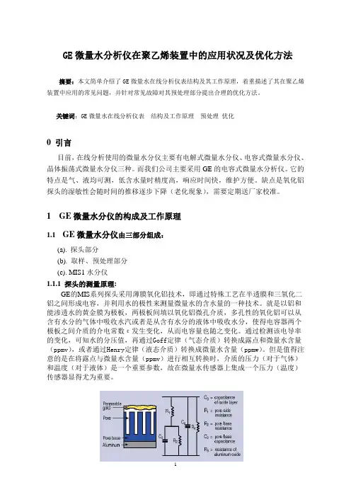
1 GE微量水分仪的构成及工作原理1.1 GE微量水分仪由三部分组成:(a). 探头部分(b). 取样、预处理部分(c). MIS1水分仪1.1.1 探头的测量原理:GE的MIS系列探头采用薄膜氧化铝技术,即通过特殊工艺在半透膜和三氧化二铝之间形成电容,并利用水的极性来测量微量水的含水量的一种技术。
就是以铝和能渗透水的黄金膜为极板,两极板间填以氧化铝微孔介质,多孔性的氧化铝可以从含有水分的气体中吸收水汽或者是从含有水分的液体中吸收水分,使得电容器两个极板之间介质的介电常数ε发生变化,从而电容量也随之变化。
通过检测该电导率的变化,可知水的分压值,再通过Goff定律(气态介质)转换成露点和微量水含量(ppmv),或者通过Henry定律(液态介质)转换成微量水含量(ppmw)。
但是值得注意的是在将露点与微量水含量(ppmv)进行相互转换时,介质的压力(对于气体)和温度(对于液体)是一个重要参数,故在微量水传感器上集成一个压力(温度)传感器显得尤为重要。
图1 电极及电容转换电路示意图故本次选用的MIS探头由TF探头和MISPE智能化前置电子处理器组成,可以测量气体和非水液体中从微量到常量的水分含量,可以满足不同量程,不同相态物质的测量。
同时此系列探头直接内置了温度、压力测量的元件,从而免除了安装与使用分离的温度、压力探头所带来的不便与限制。

1
您如何测量水份含量呢
?
微量水分析仪
GE
检测控制技术
GE 梦想启动未来
11
MIS 1微量水分析仪
应用
2
3
4
5
6
7
8
9
M系列氧化铝微量水探头
TF 系列氧化铝微量水探头
MISP2 氧化铝微量水探头
应用
此种氧化铝探头可测量气体和非水液体中从微量到常量的微量水份含量。
它需要与GE 检测控制技术
20
21
MG 101˘MIS 1 ҃ ͘
22
22
CH-M-P-2013-03GE检测控制技术
GE 检测控制技术业务是一个行业领先创新者,业务涉及传感测量,无损检测技术,状态监测,与自动化优化控制领域,帮客户实现精确、高效和安全。
旗下产品广泛应用于航空航天、石油天然气、电力、运输、医疗等行业。
它在25个国家拥有超过40家企业,隶属于GE 石油天然气集团,为客户提供更环保,更智能,更高效的解决方案。
中国客服中心电话:800 915 9966
/zh
13。
微量水分测定仪测定仪操作规程一、概述本设备采用卡尔一菲休库仑滴定法,对不同物质进行微量水分测定,是一种最可靠的方法。
HTWS-6型微量水分测定仪成功的应用了这一方法。
二、样品测定1、液体样品以含量计算公式F3、F4为例:在仪器平衡的状态下(如图6),根据样品的含水量选择适当的进样器。
如前面所述的参数设定方法设定所进样品的体积V、密度SG和所用的公式F3(或F4)。
用待测试样冲洗所用的进样器,然后吸取V体积的样品,按【启动】后在60秒内从进样口注入样品,仪器将自动测定并打印结果。
测定完成后若需储存,可按【确认】键来存储结果;要进行下次测定根据仪器提示如上操作即可。
注:仪器在测定过程中可按【退出】键进行仪器设定,终点之前的设定都有效。
2、固体样品以Fl、F2为例:固体试样可能是粉末颗粒和团块等形状(大的团必须捣碎),可用V形管固体进样器(厂方可提供)进样。
V形管固体进样器干燥后,装入适量的固体样品,然后称重(总重W),根据参数设定的方法设定好公式Fl(或F2)及W(总重),按【启动】后从进样口加入样品,然后再称重(皮重w),输入参数w,仪器到达终点并打印结果即可。
注:公式Fl、F3、F5结果为PPm,F2、F4、F6为百分率。
3、历史数据每次试验结束后可以按【确认】键对数据进行存储,如要查询可在图10的界面下选择历史数据按【确认】键进行查询。
三、注意事项1、电解池的注意事项(1)在正常的测定过程中,每100毫升电解液可与不小于l 克的水反应,如测定时间过长,电解液敏感下降,应更换新鲜电解液。
(2)阴极室中的电解液,如果在滴定过程中发现释放出强烈的气泡或电解液被污染成褐色,此时空白电流会增大,测量的再现性降低,还会使到达终点的时间加长,这种情况应尽快更换电解液。
(3)滴定时间超过半个小时,仪器尚不能稳定,此时应按搅拌开关停止搅拌,观察陶瓷滤板下部阳极上是否有明显的棕色碘产生,如果没有或产碘很少,则应更换电解液。
NRWS-8微量水份测试仪使用说明书武汉南瑞西高电气实业有限公司第一章概述本仪器采用卡尔——菲休库仑滴定法,对不同物质进行微量水分测定,是一种最可靠的方法,本微量水分测定仪成功的应用了这一方法,并采用了微计算机控制,其分析速度快,精度高,液晶屏中文显示,自动打印,且有仪器故障自诊,菜单选择等功能,以达到更好的操作与使用,具有操作简单,全自动的分析仪器。
是变压器油水分分析的最理想仪器。
第二章技术参数滴定方式:微计算机控制库仑滴定测量范围:1ug一100mg(典型值10ug一10mg)分辨率:0.1ug电解控制:自动电解电流控制(最大400mA)滴定速度:2.5mg/min(最大)准确度:10ug一100g±3ug1mg以上转化为0.3%(不含进样误差)终点显示:信息显示、蜂呜器响、终点指示灯亮日期:年月日小时分钟打印机:16个字符针式打印纸宽44毫米电源:交流220V±10% 50Hz±5%功率:60VA使用环境温度:5-40~C使用环境温度:≤90%夕L型尺寸:290X380X120重量:9kg第三章工作原理卡尔——菲休试剂同水的反应为:12+S02+3C5H5N+H20--2C5H5N·HI+C5H5N·S03…………………………………①C5H5N·SO3+CH30H—C5H5N·HS04CH……………………………………②所用试剂溶液是由占优势的碘和充有二氧化硫的砒啶,甲醇等混合而成,把样品加人到试剂中,在阳极上由电解所产生的碘与样品中的水起反映,在阳极上由电解所产生的碘与样品中的水起反映,根据法拉第定律,碘与电量成正比地产生出来。
2I- +2e—I21摩尔碘与1摩尔水质量反应,因此1mg水相当于10.71库仑电量,根据这个原理,水含量可以从电解所需要的电量中直接确定,经仪器计算,在显示器上直接显示出测定样品中的含水量。
第四章结构物征及使用方法仪器前面板与后面板说明(见图l、2)1、液晶显示屏2、打印机3、终点指示灯4、电解开关指示灯5、启动键在每个样品注入前按一下此键,指示灯亮,显示器复位为零。
容量法微量水测定仪使用说明书来源:中国分析仪器网 http://fenxi17一、容量法微量水测定仪的安全和使用:1.1 人身安全及保护措施确保所使用的电源要有可靠接地线!如未接地,可能导致人身伤亡事故。
请不要在有爆炸危险性的环境内工作!仪器外壳并非完全气闭,存在造成爆炸的可能性。
使用化学品和溶剂时,请遵照制造商的使用指导和通用实验室安全规范!所有卡尔·费休试剂都易燃并有毒性。
如果皮肤不慎接触了卡尔·费休试剂,请立即用大量的水冲洗。
如果眼睛不慎接触了卡尔·费休试剂,请立即用大量的水冲洗并注意咨询医生。
1.2 操作安全保护措施不要打开仪器外壳,如有异常情况请与大庆市日上仪器制造有限公司技术部咨询。
仪器不得安装在有腐蚀性气体的室内,腐蚀性气体可使仪器电路腐蚀,缩短仪器的寿命。
仪器不得安装在室温低于5℃或高于40℃的场所。
仪器不能放在阳光直接照射的地方。
仪器不得安装在操作频繁的大用电量电气设备附近。
仪器不得安装在湿度大的场所或者自来水排出管的附近。
仪器不得安装在电源波动超出规定数值的地方。
2 容量法微量水测定仪原理及应用领域2.1 仪器原理卡氏容量法微量水测定仪是测定样品中水分的专用仪器。
其测定原理是基于卡尔费休(Karl Fisher)化学反应,是测定物质水分含量最专业、最准确的化学方法,以容量法卡氏试剂为标准液,当样品与卡氏试剂接触时,即与样品中的水分发生定量反应。
通过消耗标准液的体积计算出样品的含水量。
2.2 应用领域卡氏水分测定仪具有准确度高、应用范围广(适合气体、液体、固体样品)、操作简单等优点,广泛适用于石油、化工、电力、制药等领域。
3容量法微量水测定仪主要功能与特点3.1 液体、固体、气体或粘性样品中水分测定3.2 等当点设置3.3 大屏幕LCD中文菜单显示3.4 100组实验数据存储3.5 十种分析方法,自由设置3.6 漂移自动扣除3.7 外接打印机、天平、计算机3.8 轻触式操作键盘,防尘防腐蚀,操作者可以通过键盘设定或修改仪器参数,即使滴定过程中也可以随时修改参数,无需中断正在进行中的滴定。
1.目的:建立卡氏微量水分测定仪标准操作规程,确保检验员能正确使用维护保养。
2.范围:适用于ZDJ-2S型卡氏微量水分测定仪的使用和维护保养。
3.职责:检验员负责对本仪器的正确使用和维护保养。
4.内容:4.1仪器使用操作方法4.1.1将仪器接通电源,打开仪器后面板开关至“开”位置。
4.1.2清洗滴定管:按仪器面板上“清洗”键进入清洗滴定管选项,输入清洗次数和每次清洗体积,按仪器面板上“启动”键,仪器开始清洗滴定管,使卡尔费休试液充满整个仪器进出液管。
4.1.3滴定管清洗完毕后,按自动给排液器“进液”按钮,向滴定池内加入试验规定的溶剂,将滴定池内的电极和出液管浸没(约需溶剂20~50ml),同时开启搅拌器。
4.1.4对试验样品进行水分测定前,依次对仪器系统进行预滴定、水分漂移值测量、水分标定测量操作。
4.1.4.1预滴定:按仪器面板上“样品”键,通过“↑/↓”键,选择“水分预滴定”,按“确认”键,启动预滴定过程。
开始预滴定时,仪器显示屏显示当前滴定液消耗量、当前漂移值及电流值。
预滴定达到平衡后时,预滴定停止,此时按“确认”键,系统保持平衡状态,仪器显示屏显示当前的漂移值和电流值。
4.1.4.2水分漂移值测量:按仪器面板上“样品”键,通过“↑/↓”键,选择“水分漂移”,按“确认”键,仪器通过4分钟自动测定漂移值。
漂移值测定完毕后,按“确认”键,系统保持平衡状态,仪器显示屏显示当前的漂移值和电流值。
4.1.4.3水分标定测量:按仪器面板上“样品”键,通过“↑/↓”键,选择“水分标定”,将微量进样器吸取5μl纯化水在电子称上称重后注入仪器滴定池中,在仪器控制面板上输入水的重量,按“确认”键后选择“测量”,再按“确认”、“启动”键,当结果出来后,按“确认”保存。
按上述水分标定操作同样做三份平衡样,取其平均值,在等待测量标定值状态下,选择“3.输入”,将标定平均值手工输入标定值,按“确认”键返回。
4.1.5水分测定:按仪器面板上“样品”键,通过“↑/↓”键,选择“水分样品”,按“确认”键,将按试验要求称取的样品倒入滴定池中,塞好池塞,将样品信息输入,再按“确认”、“启动”键,仪器即开始进行滴定。
zdj-1s卡尔微量水分测定仪使用手册卡尔克微量水分测定仪(ZDJ-1s)采用全不锈钢结构,整体重量轻;独特的动态旋钮设计,控制精度高;采用精确控制的动态振动补偿技术、振动范围宽为0.1~500 g/min;仪器可以测量样品与空气之间所形成的相对压力差、相对温度差值以及各种水分。
同时,根据检测目的设置不同的采样频率,保证了操作的灵活性及准确性。
卡尔克微量水分测定仪适用于各类产品、食品、医药等,为客户提供安全、可靠、高品质的产品。
本仪器采用精密的压差式采样技术,对样品进行高压处理。
•1、仪器安装与调试·检查各部件是否安装牢固,以免出现问题;·请注意各部件之间的接线正确安装,避免有松动;·连接好所有信号线和信号开关;·如果连接过程中有松动,请注意进行修复;·请仔细检查电源线和信号开关是否连接正确:·请勿将电源插头插入任何不正常的插座。
•2、使用方法将干燥剂(或无水乙醇)倒入微量水位计上,将水位计旋入样品杯,按仪器的操作步骤正确无误后在干燥剂上滴几滴清水便可使用了。
用干燥剂滴一滴水至水滴中并轻轻转动干燥器即可使水分扩散出来。
然后再用水位计在干燥器中滴几滴水,如滴数大于100 g则表明该样品已被湿润剂浸过,用天平称取水分含量为20 g的水样5 ml (1 ml=0.01 g)进行称量;若100 g水样在5-10 min内没有被水浸透则说明样品已被湿润,在此情况下可用天平称取5g-10g的水样进行试验,同时也可测量出100 g以下样品及100*10-50的水,用天平称取50毫升水样即可观察样品水分的变化。
•3、试验过程中的注意事项测量完成后,需检查仪器是否正常工作。
检测完成后,若仪器出现异常波动,请检查并调试传感器,如发现异常先关闭电源,然后用仪器内所需的气体调节阀门打开后再将检测器关好;如发现异常立刻停止并向技术人员汇报。
仪器在使用过程中有哪些注意事项?操作规程?试样运输与保存过程中注意:所有样品都应妥善保管并避免阳光直射。
GE微量水分析仪(蒋彩飞)GE微量水分析仪在聚乙烯装置中的应用状况及优化方法摘要:本文简单介绍了GE微量水在线分析仪表结构及其工作原理,着重描述了其在聚乙烯装置中应用的常见问题,并针对常见故障对其预处理部分提出合理的优化方法。
关键词:GE微量水在线分析仪表结构及工作原理预处理优化0 引言目前,在线分析使用的微量水分仪主要有电解式微量水分仪、电容式微量水分仪、晶体振荡式微量水分仪三种。
而我们公司主要采用GE的电容式微量水分析仪。
它的特点是气、液均可测,低含水量时精度高,响应时间快,维护方便。
缺点是氧化铝探头的湿敏性会随时间的推移逐步下降(老化现象),需要定期送厂家校准。
1 GE微量水分仪的构成及工作原理1.1 GE微量水分仪由三部分组成:(a). 探头部分(b). 取样、预处理部分(c). MIS1水分仪1.1.1 探头的测量原理:GE的MIS系列探头采用薄膜氧化铝技术,即通过特殊工艺在半透膜和三氧化二铝之间形成电容,并利用水的极性来测量微量水的含水量的一种技术。
就是以铝和能渗透水的黄金膜为极板,两极板间填以氧化铝微孔介质,多孔性的氧化铝可以从含有水分的气体中吸收水汽或者是从含有水分的液体中吸收水分,使得电容器两个极板之间介质的介电常数ε发生变化,从而电容量也随之变化。
通过检测该电导率的变化,可知水的分压值,再通过Goff定律(气态介质)转换成露点和微量水含量(ppmv),或者通过Henry定律(液态介质)转换成微量水含量(ppmw)。
但是值得注意的是在将露点与微量水含量(ppmv)进行相互转换时,介质的压力(对于气体)和温度(对于液体)是一个重要参数,故在微量水传感器上集成一个压力(温度)传感器显得尤为重要。
图1 电极及电容转换电路示意图故本次选用的MIS探头由TF探头和MISPE智能化前置电子处理器组成,可以测量气体和非水液体中从微量到常量的水分含量,可以满足不同量程,不同相态物质的测量。
同时此系列探头直接内置了温度、压力测量的元件,从而免除了安装与使用分离的温度、压力探头所带来的不便与限制。
GE IndustrialSensingMoisture Monitor Series 3 HygrometerAbridged ManualGE IndustrialSensingMoisture Monitor Series 3HygrometerAbridged Manual914-110A4August 2004Moisture Monitor Series 3 Hygrometer is a GE Panametrics product. GE Panametrics has joined other GE high-technology sensing businesses under a new name—GE Industrial, Sensing.Warranty Each instrument manufactured by GE Infrastructure Sensing, Inc. iswarranted to be free from defects in material and workmanship.Liability under this warranty is limited to restoring the instrument tonormal operation or replacing the instrument, at the sole discretion ofGE Infrastructure Sensing, Inc. Fuses and batteries are specificallyexcluded from any liability. This warranty is effective from the date ofdelivery to the original purchaser. If GE Infrastructure Sensing, Inc.determines that the equipment was defective, the warranty period is:•one year for general electronic failures of the instrument•one year for mechanical failures of the sensorIf GE Infrastructure Sensing, Inc. determines that the equipment wasdamaged by misuse, improper installation, the use of unauthorizedreplacement parts, or operating conditions outside the guidelinesspecified by GE Infrastructure Sensing, Inc., the repairs are notcovered under this warranty.The warranties set forth herein are exclusive and are in lieu ofall other warranties whether statutory, express or implied(including warranties of merchantability and fitness for aparticular purpose, and warranties arising from course ofdealing or usage or trade).Return Policy If a GE Infrastructure Sensing, Inc. instrument malfunctions within thewarranty period, the following procedure must be completed:1.Notify GE Infrastructure Sensing, Inc., giving full details of theproblem, and provide the model number and serial number of theinstrument. If the nature of the problem indicates the need forfactory service, GE Infrastructure Sensing, Inc. will issue a RETURNAUTHORIZATION number (RA), and shipping instructions for thereturn of the instrument to a service center will be provided.2.If GE Infrastructure Sensing, Inc. instructs you to send yourinstrument to a service center, it must be shipped prepaid to theauthorized repair station indicated in the shipping instructions.3.Upon receipt, GE Infrastructure Sensing, Inc. will evaluate theinstrument to determine the cause of the malfunction.Then, one of the following courses of action will then be taken:•If the damage is covered under the terms of the warranty, theinstrument will be repaired at no cost to the owner and returned.•If GE Infrastructure Sensing, Inc. determines that the damage is notcovered under the terms of the warranty, or if the warranty hasexpired, an estimate for the cost of the repairs at standard rateswill be provided. Upon receipt of the owner’s approval to proceed,the instrument will be repaired and returned.Table of ContentsChapter 1: G eneral InformationIntroduction. . . . . . . . . . . . . . . . . . . . . . . . . . . . . . . . . . . . . . . . . . . . . . . . . . . . . . . . . . . . . . . . . . . . . . . . . . . . 1-1 Unpacking the Series 3 . . . . . . . . . . . . . . . . . . . . . . . . . . . . . . . . . . . . . . . . . . . . . . . . . . . . . . . . . . . . . . . . . 1-1 Checking the Delta F Oxygen Cell for Leakage . . . . . . . . . . . . . . . . . . . . . . . . . . . . . . . . . . . . . . . . . . . 1-2 Choosing a Site. . . . . . . . . . . . . . . . . . . . . . . . . . . . . . . . . . . . . . . . . . . . . . . . . . . . . . . . . . . . . . . . . . . . . . . . . 1-3 Grounding the Series 3 . . . . . . . . . . . . . . . . . . . . . . . . . . . . . . . . . . . . . . . . . . . . . . . . . . . . . . . . . . . . . . . . . 1-5 Moisture/Temperature Probe Considerations . . . . . . . . . . . . . . . . . . . . . . . . . . . . . . . . . . . . . . . . . . . . 1-5 Temperature Range . . . . . . . . . . . . . . . . . . . . . . . . . . . . . . . . . . . . . . . . . . . . . . . . . . . . . . . . . . . . . . . . 1-6 Moisture Condensation . . . . . . . . . . . . . . . . . . . . . . . . . . . . . . . . . . . . . . . . . . . . . . . . . . . . . . . . . . . . . 1-6 Static or Dynamic Use . . . . . . . . . . . . . . . . . . . . . . . . . . . . . . . . . . . . . . . . . . . . . . . . . . . . . . . . . . . . . . 1-6 Pressure . . . . . . . . . . . . . . . . . . . . . . . . . . . . . . . . . . . . . . . . . . . . . . . . . . . . . . . . . . . . . . . . . . . . . . . . . . . 1-7 Long-Term Storage & Operational Stability . . . . . . . . . . . . . . . . . . . . . . . . . . . . . . . . . . . . . . . . . . 1-7 Freedom from Interference . . . . . . . . . . . . . . . . . . . . . . . . . . . . . . . . . . . . . . . . . . . . . . . . . . . . . . . . . 1-7 Corrosive Materials . . . . . . . . . . . . . . . . . . . . . . . . . . . . . . . . . . . . . . . . . . . . . . . . . . . . . . . . . . . . . . . . . 1-7 Sample System Guidelines. . . . . . . . . . . . . . . . . . . . . . . . . . . . . . . . . . . . . . . . . . . . . . . . . . . . . . . . . . . . . . 1-8 Moisture Sample Systems. . . . . . . . . . . . . . . . . . . . . . . . . . . . . . . . . . . . . . . . . . . . . . . . . . . . . . . . . . . 1-8 Oxygen Sample Systems . . . . . . . . . . . . . . . . . . . . . . . . . . . . . . . . . . . . . . . . . . . . . . . . . . . . . . . . . . . 1-9August 2004Table of Contents (cont.)Chapter 2: InstallationMounting the Hygrometer System. . . . . . . . . . . . . . . . . . . . . . . . . . . . . . . . . . . . . . . . . . . . . . . . . . . . . . 2-1 Mounting the Electronics Unit. . . . . . . . . . . . . . . . . . . . . . . . . . . . . . . . . . . . . . . . . . . . . . . . . . . . . . . 2-1 Mounting the Sample System. . . . . . . . . . . . . . . . . . . . . . . . . . . . . . . . . . . . . . . . . . . . . . . . . . . . . . . 2-1 Mounting the Oxygen Cell Assembly . . . . . . . . . . . . . . . . . . . . . . . . . . . . . . . . . . . . . . . . . . . . . . . . 2-1 Installing the Probes. . . . . . . . . . . . . . . . . . . . . . . . . . . . . . . . . . . . . . . . . . . . . . . . . . . . . . . . . . . . . . . . . . . . 2-2 Moisture Probes. . . . . . . . . . . . . . . . . . . . . . . . . . . . . . . . . . . . . . . . . . . . . . . . . . . . . . . . . . . . . . . . . . . . 2-2 Pressure Sensor. . . . . . . . . . . . . . . . . . . . . . . . . . . . . . . . . . . . . . . . . . . . . . . . . . . . . . . . . . . . . . . . . . . . 2-3 Delta F Oxygen Cell. . . . . . . . . . . . . . . . . . . . . . . . . . . . . . . . . . . . . . . . . . . . . . . . . . . . . . . . . . . . . . . . . 2-3 Making Basic Electrical Connections . . . . . . . . . . . . . . . . . . . . . . . . . . . . . . . . . . . . . . . . . . . . . . . . . . . . 2-5 Making Channel Connections . . . . . . . . . . . . . . . . . . . . . . . . . . . . . . . . . . . . . . . . . . . . . . . . . . . . . . . 2-6 Connecting the Power. . . . . . . . . . . . . . . . . . . . . . . . . . . . . . . . . . . . . . . . . . . . . . . . . . . . . . . . . . . . . . 2-6 Connecting Moisture Probes . . . . . . . . . . . . . . . . . . . . . . . . . . . . . . . . . . . . . . . . . . . . . . . . . . . . . . . . 2-7 Connecting the Delta F Oxygen Cell . . . . . . . . . . . . . . . . . . . . . . . . . . . . . . . . . . . . . . . . . . . . . . . .2-10 Establishing a Gas Flow Through the Oxygen Cell . . . . . . . . . . . . . . . . . . . . . . . . . . . . . . . . . . . . . . .2-14 Connecting Optional Recorder Outputs. . . . . . . . . . . . . . . . . . . . . . . . . . . . . . . . . . . . . . . . . . . . . . . . .2-16 Accessing the Channel Cards . . . . . . . . . . . . . . . . . . . . . . . . . . . . . . . . . . . . . . . . . . . . . . . . . . . . . .2-16 Setting the Switch Blocks . . . . . . . . . . . . . . . . . . . . . . . . . . . . . . . . . . . . . . . . . . . . . . . . . . . . . . . . . .2-16 Replacing the Channel Card . . . . . . . . . . . . . . . . . . . . . . . . . . . . . . . . . . . . . . . . . . . . . . . . . . . . . . .2-17 Connecting the Recorders . . . . . . . . . . . . . . . . . . . . . . . . . . . . . . . . . . . . . . . . . . . . . . . . . . . . . . . . .2-17 Connecting Optional Alarms. . . . . . . . . . . . . . . . . . . . . . . . . . . . . . . . . . . . . . . . . . . . . . . . . . . . . . . . . . .2-18August 2004Table of Contents (cont.)Chapter 3: Setup & OperationStartup Procedure. . . . . . . . . . . . . . . . . . . . . . . . . . . . . . . . . . . . . . . . . . . . . . . . . . . . . . . . . . . . . . . . . . . . . . 3-1 Powering Up . . . . . . . . . . . . . . . . . . . . . . . . . . . . . . . . . . . . . . . . . . . . . . . . . . . . . . . . . . . . . . . . . . . . . . . 3-1 Using the Keypad and Passcode . . . . . . . . . . . . . . . . . . . . . . . . . . . . . . . . . . . . . . . . . . . . . . . . . . . . 3-1 Displaying Measurements . . . . . . . . . . . . . . . . . . . . . . . . . . . . . . . . . . . . . . . . . . . . . . . . . . . . . . . . . . . . . . 3-2 Displaying Measurement Mode and Units . . . . . . . . . . . . . . . . . . . . . . . . . . . . . . . . . . . . . . . . . . . 3-3 Menu Map . . . . . . . . . . . . . . . . . . . . . . . . . . . . . . . . . . . . . . . . . . . . . . . . . . . . . . . . . . . . . . . . . . . . . . . . . . . . . 3-5 Adjusting the Screen Contrast. . . . . . . . . . . . . . . . . . . . . . . . . . . . . . . . . . . . . . . . . . . . . . . . . . . . . . . . . . . 3-6 Entering System Constants . . . . . . . . . . . . . . . . . . . . . . . . . . . . . . . . . . . . . . . . . . . . . . . . . . . . . . . . . . . . . 3-6 Entering a Saturation Constant . . . . . . . . . . . . . . . . . . . . . . . . . . . . . . . . . . . . . . . . . . . . . . . . . . . . . . . . . 3-8 Setting Up the Recorders . . . . . . . . . . . . . . . . . . . . . . . . . . . . . . . . . . . . . . . . . . . . . . . . . . . . . . . . . . . . . . . 3-9 Setting Up the Alarms . . . . . . . . . . . . . . . . . . . . . . . . . . . . . . . . . . . . . . . . . . . . . . . . . . . . . . . . . . . . . . . . .3-10August 2004Table of Contents (cont.)Chapter 4: Calibration & MaintenanceAluminum Oxide Moisture Probes . . . . . . . . . . . . . . . . . . . . . . . . . . . . . . . . . . . . . . . . . . . . . . . . . . . . . . . 4-1 Probe Cable Calibration. . . . . . . . . . . . . . . . . . . . . . . . . . . . . . . . . . . . . . . . . . . . . . . . . . . . . . . . . . . . . 4-1 Probe Cleaning. . . . . . . . . . . . . . . . . . . . . . . . . . . . . . . . . . . . . . . . . . . . . . . . . . . . . . . . . . . . . . . . . . . . . 4-2 Delta F Oxygen Cells . . . . . . . . . . . . . . . . . . . . . . . . . . . . . . . . . . . . . . . . . . . . . . . . . . . . . . . . . . . . . . . . . . . 4-3 Electrolyte Maintenance. . . . . . . . . . . . . . . . . . . . . . . . . . . . . . . . . . . . . . . . . . . . . . . . . . . . . . . . . . . . 4-4 Calibrating the Delta F Oxygen Cell. . . . . . . . . . . . . . . . . . . . . . . . . . . . . . . . . . . . . . . . . . . . . . . . . . 4-4 Entering Background Gas Calibration Data . . . . . . . . . . . . . . . . . . . . . . . . . . . . . . . . . . . . . . . . . . 4-7 Setting Up a New Probe or Sensor . . . . . . . . . . . . . . . . . . . . . . . . . . . . . . . . . . . . . . . . . . . . . . . . . . . . . . 4-9 Reconfiguring a Channel for a New Sensor . . . . . . . . . . . . . . . . . . . . . . . . . . . . . . . . . . . . . . . . . . 4-9 Entering Calibration Data for New Probes/Sensors. . . . . . . . . . . . . . . . . . . . . . . . . . . . . . . . . .4-12 Setting Up a New Channel Card. . . . . . . . . . . . . . . . . . . . . . . . . . . . . . . . . . . . . . . . . . . . . . . . . . . . . . . .4-17 Entering Moisture Reference Data. . . . . . . . . . . . . . . . . . . . . . . . . . . . . . . . . . . . . . . . . . . . . . . . . .4-18 Entering Oxygen Reference Data. . . . . . . . . . . . . . . . . . . . . . . . . . . . . . . . . . . . . . . . . . . . . . . . . . .4-18 Entering Pressure Reference Data. . . . . . . . . . . . . . . . . . . . . . . . . . . . . . . . . . . . . . . . . . . . . . . . . .4-18Chapter 1G eneral InformationIntroduction. . . . . . . . . . . . . . . . . . . . . . . . . . . . . . . . . . . . . . . . . . . . . . . . . . . . 1-1Unpacking the Series 3 . . . . . . . . . . . . . . . . . . . . . . . . . . . . . . . . . . . . . . . . . . 1-1Checking the Delta F Oxygen Cell for Leakage . . . . . . . . . . . . . . . . . . . . . 1-2Choosing a Site. . . . . . . . . . . . . . . . . . . . . . . . . . . . . . . . . . . . . . . . . . . . . . . . . 1-3Grounding the Series 3 . . . . . . . . . . . . . . . . . . . . . . . . . . . . . . . . . . . . . . . . . . 1-5Moisture/Temperature Probe Considerations. . . . . . . . . . . . . . . . . . . . . . 1-5Sample System Guidelines. . . . . . . . . . . . . . . . . . . . . . . . . . . . . . . . . . . . . . . 1-8August 2004 Introduction The GE Infrastructure Sensing, Inc. Moisture Monitor Series 3 is aone- or two-channel analyzer designed to measure dissolved moistureconcentration in gases and non-aqueous liquids, and dissolvedoxygen concentration in gases.A microprocessor-based instrument, the Series 3 combines hardwareand software to make various measurements. The user connects theneeded inputs (moisture probes, pressure transmitters, oxygen cells,etc.) to the back panel of the electronics unit using the appropriatecables. Typically, the user installs moisture probes and oxygen cellsinto the process using a sample system that is specifically designedfor the application. The sample system delivers a sample of theprocess gas or liquid to the probes. The probes then send signals tothe Series 3 electronics unit, which interprets the signals and convertsthem into measurements.Users typically install the Series 3 as part of a complex processsystem, which includes components such as filters, pumps, andpressure regulators. In such an environment, probes and other parts ofthe system may be subjected to environmental hazards, such as hightemperature, pressure extremes, corrosive elements, and mechanicalvibrations.!WARNING!To ensure the safe operation of this unit, you must installand operate the Series 3 as described in this manual. Inaddition, be sure to follow all applicable safety codes andregulations for installing electrical equipment in your area. Unpacking the Series 3Upon receipt, unpack the Series 3 and make sure all the parts anddocumentation listed on the packing slip are included. The packingslip may not list the Calibration Data Sheet(s), which are usuallypacked in the plastic storage case with the moisture, oxygen, andpressure probes. You may also find the Calibration Data Sheet(s) inan envelope taped to the Series 3. There should be one CalibrationData Sheet for each probe.Be sure to inspect each component, including the sample system, forevidence of mishandling. If anything has been damaged, report this tothe carrier and to GE Infrastructure Sensing, Inc. immediately. Youshould leave the plastic caps on the probes and the pressuretransmitters when they are not installed in the process stream. Ifanything is missing, contact GE Infrastructure Sensing, Inc.immediately.August 20041-2G eneral InformationChecking the Delta F Oxygen Cell for Leakage Before connecting the Delta F Oxygen Cell(s), you must check it fordamage and/or leakage. Depending on the application, the oxygencell may have a top drain or both a top and bottom drain for theelectrolyte reservoir. It is important to identify your cell for thefollowing procedure. Use Figure 1-1 below to identify your cell.1.Remove the top of the electrolyte reservoir.IMPORTANT:If your cell also has a bottom drain, make sure thatthe electrolyte discharge valve, mounted on the rearof the oxygen cell, is closed (in the vertical position).See Figure 1-1 below.2.Add approximately three ounces (100 ml) of distilled water to thereservoir and replace the top.ing the min/max window (see Figure 1-2 on the next page) onthe oxygen cell, check the water level. The water should coverabout 60% of the window.4.Let the oxygen cell stand for about 6 hours; then check for anyleakage.5.If there is no leakage, drain the cell completely.If the cell leaks, see the warranty information at the beginning of thismanual.August 2004 Checking the Delta F(cont.)Choosing a Site The Series 3 is available in rack, bench or panel mounts that aresuitable for most indoor installations, as well as weatherproof andexplosion-proof configurations. See the drawings at the end of thischapter for an example of each enclosure.You should have discussed environmental and installation factorswith an applications engineer or field sales person by the time youreceive the Series 3. The equipment should be suited to theapplication and installation site.Before installing the unit, read the guidelines below to verify that youhave selected the best installation site.IMPORTANT:For compliance with the EU’s Low Voltage Directive(IEC 1010), this unit requires an external powerdisconnect device. The disconnect device for this unitis its power cord.G eneral Information1-3August 20041-4G eneral InformationChoosing a Site (cont.)!WARNING!Division 2 applications may require special installation.Consult the National Electric Codeand/or the Canadian Electrical Code for proper installation requirements. The analyzer must be configured in asuitable equipment enclosure and installed according tothe sections of the National Electric Code, Article 500, andCanadian Electrical Code, Section 18, that pertain to thehazardous environment classification in which theelectronics will be used.•Choose an installation site for the probes and sample systems thatis as close to the process line as possible. Avoid long runs ofconnecting tubing. If long distances are unavoidable, a fastsampling by-pass loop is recommended. Do not install any othercomponents, such as filters, ahead of the probes or sample systemunless instructed by GE Infrastructure Sensing, Inc. to do so.•Observe all normal safety precautions. Use probes within theirmaximum pressure and temperature ratings.•Although the Series 3 may not need to be accessed during normaloperation, install the electronics unit at a convenient location forprogramming, testing and servicing. A control room or instrumentshed are typical locations.•Locate the electronics unit away from high temperatures, strongelectrical transients, mechanical vibrations, corrosive atmospheres,and any other conditions that could damage or interfere with theSeries 3 operation.•Protect the probe cables from excessive physical strain (bending,pulling, twisting, etc.). In addition, do not subject the cables totemperatures above 65°C (149°F) or below –50°C (–58°F).•Observe the proper cable restrictions for the probes as follows:•The M Series and TF Series probes require specially shieldedcable. You can locate the M and TF probes up to 600 m (2,000ft) from the Series 3. If you are measuring pressure with a TFprobe, the cable length should not exceed 152 m (500 ft).•The Delta-F Oxygen Cell uses a four-wire shielded cable 22AWG). Cells with a range from 0 to 1/10/100 ppm v or 0 to 0.5/5/50 ppm v can be located up to 15 m (50 ft) away. All othercells can be located up to 91 m (300 ft) away.Consult GE Infrastructure Sensing, Inc. for remote location of theoxygen cell and cable restrictions for other sensors.August 2004 Grounding the Series 3The Series 3 case is grounded to the electrical system safety groundthrough the third wire in the power connector and cord (refer toFigure 1-3 below). This ground should not be removed.Moisture/Temperature Probe Considerations The M Series and TF Series probes consist of an aluminum oxide sensor mounted on a connector head. Standard probe mounts include a protective stainless-steel shield.The probe sensor materials and housing maximize durability and insure a minimum of water-adsorbing surfaces in the vicinity of the aluminum oxide surface. A sintered stainless-steel shield is used to protect the sensor from high flow rates and particulate matter. The shield should not be removed except upon advice from GE Infrastructure Sensing, Inc..The sensor has been designed to withstand normal shock and vibration. You should make sure that the active sensor surface is never touched or allowed to come into direct contact with foreign objects, since this may adversely affect performance.Observing these few simple precautions will result in a long and useful probe life. GE Infrastructure Sensing, Inc. recommends that probe calibration be checked routinely, at 6-month intervals, or as recommended by our applications engineers for your particular application.The probe will measure the water vapor pressure in its immediate vicinity; therefore, readings will be influenced by its proximity to the system walls, materials of construction, and other environmental factors. The sensor can be operated under vacuum or pressure, flowing or static conditions.Observe the environmental precautions noted on the next page.G eneral Information1-5August 2004Temperature Range The standard probe is operable from –110°C to +70°C (–166°F to158°F).Moisture Condensation Be sure the temperature is at least 10°C (18°F) higher than the dew/frost point temperature. If this condition is not maintained, moisturecondensation could occur on the sensor or in the sample system,which will cause reading errors. If this happens, dry out the probefollowing the procedures outlined in Chapter 3.Static or Dynamic Use The sensor performs equally well in still air or where considerableflow occurs. Its small size makes it ideal for measuring moistureconditions within completely sealed containers or dry boxes. It willalso perform well under gas flow conditions as high as 10,000 cm/secand liquid flow conditions to 10 cm/sec. Refer to Table 1-1 below andTable 1-2 on the next page for maximum flow rates in gases andliquids.Table 1-1: Maximum G as Flow RatesBased on the physical characteristics of air at a temperature of77°F and a pressure of 1 atm, the following flow rates willproduce the maximum allowable gas stream linear velocity of10,000 cm/sec in the corresponding pipe sizes.Inside Pipe Diameter (in.)G as Flow Rate (cfm)0.2570.50270.75601.01072.04293.09664.01,7185.02,6846.03,8657.05,2618.06,8719.08,69710.010,73711.012,99112.015,4611-6G eneral InformationG eneral Information 1-7August 2004Static or Dynamic Use(cont.)Pressure The moisture probe always senses the correct water vapor pressureregardless of total ambient pressure. The moisture sensor measureswater vapor under vacuum or high pressure conditions from as littleas 5 µm Hg to as high as 5,000 psi total pressure.Long-Term Storage & Operational Stability Sensors are not affected by continuous abrupt humidity changes ordamaged by exposure to saturation conditions even when stored.However, you should store probes in their original shipping containerin a clean, dry location. If the probe is saturated during storage, referto Moisture Condensation on later in this chapter before installing theprobe. For best performance, do not store probes longer than one totwo years from their calibration date.Freedom from Interference The sensor is completely unaffected by the presence of a wide varietyof gases or organic liquids. Large concentrations of hydrocarbongases, Freon ®, ozone, carbon dioxide, carbon monoxide, andhydrogen have no effect on sensor water vapor indications. Thesensor will operate properly in a multitude of gaseous or non-conductive liquid environments.Corrosive MaterialsAvoid all materials that are corrosive or otherwise damaging toaluminum or aluminum oxide. These include strongly acidic or basicmaterials and primary amines.Table 1-2: Maximum Liquid Flow RatesBased on the physical characteristics of benzene at atemperature of 77°F , the following flow rates will produce themaximum allowable fluid linear velocity of 10 cm/sec in thecorresponding pipe sizes.Pipe I.D. (in.)Flow Rate (gal/hr)Flow Rate (l/hr)0.253110.5012460.75271031.0481822.01937303.04341,6424.07712,9195.01,2054,5616.01,7356,5677.02,3618,9398.03,08411,6759.03,90314,77610.04,81918,24311.05,83122,07412.06,93926,269August 20041-8G eneral InformationSample System Guidelines A sample system is required for oxygen measurement and, althoughnot mandatory, is highly recommended for moisture measurement.The purpose of a sample system is to condition or control a samplestream to within the specifications of a probe. The applicationrequirements determine the design of the sample system. GEInfrastructure Sensing, Inc. applications engineers will makerecommendations based on the following general guidelines.Moisture Sample SystemsTypically, sample systems should contain as few components aspossible and all or most of those components should be locateddownstream of the measurement probe. Figure 1-4 below shows anexample of a basic sample system consisting of an explosion-proofhousing with a sample cell, a filter, a flow meter, a vent valve andtwo-shut off valves, one at the inlet and one at the outlet.The sample system components should not be made of any materialthat will affect measurements. A sample system may include a filterto remove particulates from the sample stream or a pressure regulatorto reduce or control the pressure of the stream. However, mostcommon filters and pressure regulators are not suitable for samplesystems because they have wetted parts that may absorb or releasecomponents (such as moisture) into the sample stream. They may alsoallow ambient contamination to enter the sample stream. In general,you should use stainless steel material for all wetted parts.August 2004 Oxygen Sample Systems Oxygen sample systems are required and can be be ordered from GEInfrastructure Sensing, Inc. for bench or wall mounting, or you canbuild your own sample system by using the following guidelines.IMPORTANT:The GE Infrastructure Sensing, Inc. warranty is void,if the sample system does not have a relief valve.The basic sample system requirements are (see Figure 1-5 below):1.The oxygen cell requires a sample gas flow of2.0 to 2.5 SCFH.2.The sample gas pressure in the cell must be between 0.0 and 1.0psig. The pressure must not exceed 1.0 psig.3.A 10 psig pressure relief valve installed upstream of the oxygencell is required to prevent over-pressure.4.A flow meter is required to measure the flow.5.A pressure gauge is required to measure the pressure.6.A flow regulating or needle valve is required to regulate flow andshould be located upstream of the cell.7.A pressure regulator is required for sample gas supplies of 50 psigor greater.If a sample pump is required to draw a sample to the oxygen cell, thepump should be installed downstream of the oxygen cell. This willalso require you to install a vacuum relief valve set at 1.0 psigbetween the oxygen cell and the pump.G eneral Information1-9。