BY3246W-370直流减速电机使用说明
- 格式:pdf
- 大小:1.29 MB
- 文档页数:1
偏航电机使用说明书本手册介绍了YEJ电磁制动三相异步电机的安装及使用方法,请仔细阅读并妥善保管,以使电机能够安全可靠有效的运行。
一.概述YEJ电磁制动三相异步电机用于驱动风力发电机偏航用齿轮箱,电机设计电压及频率为400/690V 50Hz,也可根据用户需要派生制造。
电机非驱动端安装有电磁制动器,用于电机制动,具体使用方法将在本说明书第六部分给出。
电机安装有加热带,工作电压及频率为230V 50Hz。
同时,电机还安装有温度传感器,保护温度为100℃。
二.工作条件1.海拔不超过1000m。
2.运行时环境温度:-40℃~+55℃。
3.相对湿度不超过100%。
4.空气允许含盐且含有细沙。
5.电源电压变化不超过额定值的±5%。
6.电源频率变化不超过额定值的±1%。
7.电机工作制为S3,最长连续运行时间不超过1小时。
三.运输与储存1.装卸及运输中不得拆箱,避免雨淋和剧烈震动。
2.如不立即使用,对电机的轴伸应涂防锈剂或临时性涂封材料,包装箱内需衬油毛毡纸及塑料膜,并加干燥剂。
3.存放地点应清洁,通风良好,不得有腐蚀性气体,环境温度最好不低于+3℃,避免雨淋。
四.安装和使用1.清除机体内的灰尘及轴伸的防锈层。
2.仔细检查各零部件装配是否良好,紧固件有无松动现象。
3.检查导电接触部分是否良好,如有锈斑应清除之。
4.用手轻转电机轴伸,查看转动是否灵活,并细听内部有无摩擦或碰装等杂声。
5.检查电机铭牌数据是否符合要求。
6.用500兆欧表测量绕组相间及对机壳绝缘电阻,若测得的电阻不低于表1即可使用。
低于上述值时,需将电机拆开进行干燥处理,一般情况下保持100~110℃温度烘8~10小时,干燥过程中应做好测量记录,开始每小时测一次,以后每半小时测一次,直到绝缘电阻稳定合格为止。
若无烘干装置,亦可采用通入短路电流的方法进行,此时转子应堵转,定子输入 1.5倍以下额定电流,保持发热温度70~75℃。
表17.检查接地装置是否妥善并接好地线,地线应用裸线。


User ManualTable of ContentsDrive Features (1)Drive Specifications (2)Certifications (3)Installation - Drive Dimensions (3)Motor Dimensions (mm) (4)Drive Mounting (4)Wiring (5)Menu (7)Status Monitor (9)Fault Codes (10)Factory Test Menu (11)Initial Start-up Procedure (11)Drive (Controller) Label (12)Motor Label (12)Notes (12)Drive Features∙Versatile input voltage range∙Fan-less design with mounting plate heat sink∙Simple analog controls and RS-485 digital interface∙Compact integrated system with ETM’s M100 Direct Drive Motor and MD100 Motor Drive ∙ Internal protection- Motor regeneration effects- Motor and controller over-temp- Locked rotor∙Sinusoidal current control for smooth, quiet motor operationUser Manual Drive SpecificationsUser ManualCertificationsProduct is UL Listed to standard UL 61800-5-1. EFile number E478050.Drives shall be indicated for use in a pollution degree 2 environment.Installation - Drive Dimensions4X .270”dia mounting holesUser ManualMotor Dimensions (mm)Drive MountingAll dimensions in inches. Drive shall be mounted vertically. Ensure center of heatsink is exposed to airflow, as shown above.User ManualWiringFigure 1 shows the cable connections from the motor to the drive, as well as the I/O and signal connections. Figures 2 and 3 show the wiring diagram for the motor cable and I/O terminals. Branch protection shall be provided with Class K5 fuses rated 20A maximum, or the equivalent. Note: Motor must be wired to Drive before Supply Power is turned on.Figure 1: Cable connectionsMotor Power CableStrain ReliefMotor Encoder Programming, UI BoardRemote Control I/OMain BoardSupply PowerL1, L2 (120-240VAC)Supply GroundMotor Phase White = U Black = V Red = WMotor GroundSupply Power CableStrain ReliefJumperUser ManualFigure 2: Drive to Motor WiringFigure 3: I/O Wiring DiagramUser ManualI/O TerminalsMenuFigure 4: Display and keypad layoutDisplayUp/Down KeysLeft/Right KeysStop KeyEnter KeyUser ManualOn startup, the display shows the following text:∙ The speed (in RPM) of the motor can be adjusted by pressing the UP/DOWN arrows on the keypad. ∙ Press the ENTER key to confirm the selected speed. Speed is limited by the min/max speeddetermined by the user.∙ Once the correct speed has been selected, pressing the RIGHT arrow key will start the motor in theforward/reverse direction. (Determined by Start Key menu option) ∙ Pressing the STOP key will stop the motor.∙ Holding the LEFT arrow key and then holding the ENTER key for 2 seconds (while still holding theLEFT key) will lock out the direction and speed controls on the keypad. STOP will still be available. Remote direction and speed controls will still be available. Hold LEFT and ENTER again to unlock keypad. A locked display is indicated with the symbol Ω.To access the settings menu, hold down the ENTER key for 2+ seconds. Use the UP/DOWN keys to cycle through the menu options. Use the LEFT/RIGHT keys to adjust each setting. Press the ENTER key to confirm a setting change. Table 2 shows the structure of the menu options. To exit the menu, navigate to the “To Exit Menu Press ENTER” option, and press the ENTER key.STOP 10 RPM Speed Adj Up/DwnUser ManualStatus MonitorTo access the status monitors of the drive and motor, hold the ENTER key for 3+ seconds to open the menu. Then use the UP/DOWN keys to navigate to the Monitor subsection. Use the LEFT/RIGHT keys to cycle through the different monitor options.User ManualFault CodesStatus1 and Status2 indicate possible fault codes from the drive or motor. Each status is a hexadecimal representation of a 16 bit binary word. Each bit represents a different fault. Table 4 describes the fault codes associated with each bit.User ManualFactory Test MenuThe factory test menu has several extra options for debugging and resetting the drive and motor. WARNING: the factory test menu should only be accessed by technicians troubleshooting problems with the drive or motor.To access the factory test menu, navigate to the “Exit Menu” option of the main menu, then press STOP, LEFT, RIGHT, ENTER, in order one at a time. The display will then indicate the factory test menu is active. All the standard menu features are available in the factory test menu, as well as several extra options. Table 5 shows the structure of the extra factory test options.Initial Start-up ProcedureWhen a Drive and Motor are first connected, or when the Drive has been reset to factory defaults, the Drive must perform a one-time setup procedure to align the encoder on the Motor. When the drive is powered on, the display will read “Verify Motor or Conveyor is free to move and unloaded. Press Enter to Initialize Motor…”. Once the user has verified that the Motor is wired to the Drive, and there is no load on the conveyor, press ENTER to continue. The Motor will slowly turn one revolution forward. Once complete, the display will return to the home screen and normal operations can resume.The Phase alignment can also be accessed through the Factory Test Menu. Navigate to the Phase Alignment option and press ENTER to perform the alignment.User ManualDrive (Controller) LabelMotor LabelNotesThe drive is not provided with motor overload protection, external overload protection should be considered in the end product.The drive does not provide over temperature protection, external over temperature protection should be considered in the end product.。
概述
直流减速电机,即齿轮减速电机,是在普通直流电机的基础上,加上配套齿轮减速箱。
齿轮减速箱的作用是,提供较低的转速,较大的力矩。
同时,齿轮箱不同的减速比可以提供不同的转速和力矩。
这大大提高了,直流电机在自动化行业中的使用率。
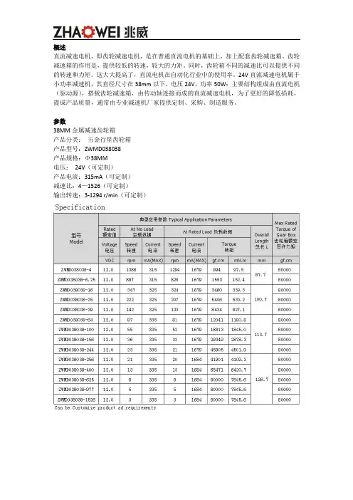
24V直流减速电机属于小功率减速机,其直径尺寸在38mm以下,电压24V,功率50W;主要结构组成由直流电机(驱动源),搭载齿轮减速箱,由传动轴连接而成的直流减速电机,为了更好的降低损耗,提成产品质量,通常由专业减速机厂家提供定制、采购、制造服务。
参数
38MM金属减速齿轮箱
产品分类:五金行星齿轮箱
产品型号:ZWMD038038
产品规格:Φ38MM
电压:24V(可定制)
产品电流:315mA(可定制)
减速比:4—1526(可定制)
输出转速:3-1294 r/min(可定制)
性能
24V直流减速电机具备体积小、功率大、减速范围广、传动效率高、寿命长、噪音低、耗能低等特点。
定制参数
按照客户需求定制直流减速电机参数:
电压:3V-24V
功率:0.5W-50W
减速比:5-1500
扭矩范围:1gf-cm到50kgf-cm;
直径范围:3.4mm-38mm
输出转速:5-2000rpm
噪音:45DB(分贝)
齿轮箱材质:塑胶、金属
用途
24V直流减速电机广泛应用在汽车驱动领域、智能家居领域、机器人传动领域、电子产品、智能穿戴设备领域、自动工业化领域。
品牌
深圳市兆威机电股份有限公司成立于2001年,是一家研发、生产精密传动系统及汽车精密注塑零组件的制造型企业,为客户提供传动方案设计,零件的生产与组装的定制化服务。
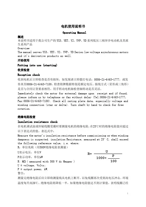
电机使用说明书Operating Manual概述本说明书适用于我公司生产的YX3、YET、Y2、YVP、YD系列低压三相异步电动机及其派生系列产品OverviewThe manual serves YX3、YET、Y2、YVP、YD Series low voltage asynchronous motors and it's derivative products as well.开始使用Putting into use (starting)收货检查Reception check收到电机后立即检查是否有损坏,如发现请立即拨打电话:0086-21-6463-1777,或发传真至0086-21-6463-7180,检查铭牌数据特别是额定电压、接线方式(星形或三角形)是否与合同订货要求相符,用手转动电机轴检查轴转动是否灵活。
Immediately check the motor for external damage upon receipt and if found, please inform us by telephone or fax without delay (Tel:0086-21-6463-1777, Fax:0086-21-6463-7180). Check all rating plate data, especially voltage and winding connection (star or delta). Turn shaft by hand to check for free rotation.绝缘电阻检查Insulation resistance check在电机调试前或怀疑线圈受潮时要测量电机的绝缘电阻,在25℃时的绝缘电阻值应超过以下表达式的值,表达式中:Measure the motor's insulation resistance before commissioning or when winding dampness is suspected. insulation Resistance, measured at 25°C, shall exceed the following reference value, i.e. where:R:单位兆欧(用500V绝缘电阻表测量)Array U表示电压,单位VP表示功率,单位kWR: MΩ( measured with 500 V dc Megger )U = voltage, Volts;P = output power, kW.警告:测量完绝缘电阻后应立即将测量线从电机上断开,以免线圈再次受到高电压冲击。
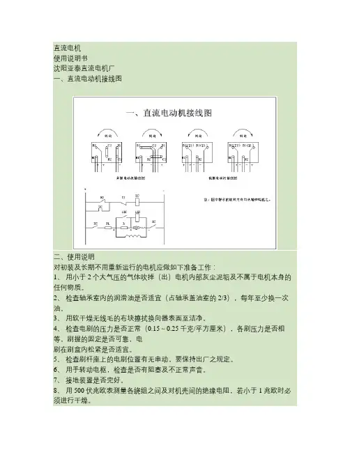
直流电机使用说明书沈阳亚泰直流电机厂一、直流电动机接线图二、使用说明对初装及长期不用重新运行的电机应做如下准备工作:1、用小于2个大气压的气体吹掉(出)电机内部灰尘泥垢及不属于电机本身的任何物质。
2、检查轴承室内的润滑油是否适宜(占轴承盖油室的2/3),每年至少换一次油。
3、用软干燥无线毛的布块擦拭换向器表面至洁净。
4、检查电刷的压力是否正常(0.15~0.25千克/平方厘米),各刷压力是否相等,刷握的固定是否可靠,电刷在刷盒内松紧是否适宜。
5、检查刷杆座上的电刷位置有无串动,要保持出厂之规定。
6、用手转动电枢,检查是否有阻塞及不正常声音。
7、接地装置是否完好。
8、用500伏兆欧表测量各绕组之间及对机壳间的绝缘电阻,若小于1兆欧时必须进行干燥。
9、检查电机出线及控制线路等联结是否正确。
三、维护及检修1、电机使用的条件应符合Z2系列小型直流电机标准JB1104-68之规定。
2、电机在额定状态工作时其各部分的温升不得超过以下各值:电枢绕组与磁场绕组B级绝缘80℃(电阻法);换向器80℃(温度计法);轴承55℃(温度计法)。
3、经常运转的电机要做到一般性检查:对电刷、刷架、换向器等进行检查。
4、定期检查:每月至少检查一次。
15、在额定负载下换向器表面上的火花不得大于1 级。
26、若换向器磨损,表面粗糙不光洁,可车削加工,云母下刻1~1.5mm。
7、电刷磨损严重者,应予更换。
(选D104并要研磨电刷)。
8、保持电机内部洁净。
9、检查各组及联接线的绝缘电阻不得小于1兆欧。
如小于1兆欧时应对绕组进行干燥。


直流传动系统使⽤说明书直流传动系统使⽤说明书第⼀部分调试⼤纲⼀、概述本连轧⽣产线直流传动系统均采⽤改制⽅式。
电机电枢的供电部分采⽤可控硅三相桥式全控整流形式,调节部分由6RA70控制器控制。
⼆、系统通电前的检查通电前⾸先应进⾏外观检查,有⽆元件损坏,接线是否松动。
检查进线调节柜、整流柜间线是否正确及柜外线连接是否正确。
检查变流器上插⼊式端⼦是否松动。
三、检查脉冲检查步骤:1.⾸先合控制器电源,设置6RA70控制器参数,基本参数有:P051=40 对于授权服务⼈员的参数值访问权P082=2 励磁的运⾏模式P083 速度实际值的选择P084 速度/电流或转矩闭环的选择P100 设定电机电枢额定电流(按电机铭牌设置)P101 设定电机电枢额定电压(按电机铭牌设置)P102 设定电机励磁额定电流(按电机铭牌设置)P140 编码器类型选择(按实际编码器设置)P141 编码器单圈脉冲数(按实际编码器铭牌设置)P142 编码器⼯作电压(按实际编码器铭牌设置)P143 电机最⾼⼯作转速(按电机铭牌设置)2.基本参数设置后,再合整流柜触发电源,然后令参数U840依次分别等于11~16和21~26,同时观察整流柜内相应的脉冲盒是否被触发(触发顺序如下所⽰),并检查触发脉冲幅值。
依次测试后须令U840等于0。
四、带电阻负载1.阻性负载开环实验:先将电机电枢线拆除,接上电阻箱作为负载。
将6RA70控制器设置为电流开环,检查电流反馈极性。
合闸顺序:⾸先令给定电位器为零,合控制器电源、操作电源、整流柜触发电源,合整流柜内触发电源和风机电源。
6RA70参数设置有:P082=0 不使⽤励磁;励磁脉冲禁⽌。
P083=3 速度实际值的选择实际EMF(K287)提供。
P084=2 在电流/转矩闭环运⾏P154=0 电枢电流调节器的I分量置零P155=1 电枢电流调节器的⽐例增益(适当调⼤即可)P602=0 电枢电流调节器实际值置零(开环控制)将“外控/内控”选择开关打⾄“内控”,将“合闸”选择开关打⾄右侧合闸,则CW1开关合闸,将“正转/反转”选择开关打⾄“正转”,这时6RA70控制器运⾏状态,调节给定电位器,⽤⽰波器观察模拟量输出端12#、13#(电流实际值)的波形,应是间隔60°的电流波形。
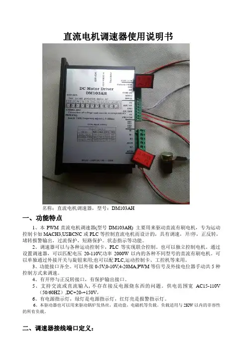
直流电机调速器使用说明书名称:直流电机调速器,型号:DM103AH一、功能特点1、本PWM直流电机调速器(型号DM103AH) 主要用来驱动直流有刷电机,专为运动控制卡如MACH3,USBCNC或PLC等控制直流电机而设计的,具有调速,开/停,正反转,堵转报警输出,过流保护,短路保护。
状态指示等功能。
2、调速器可以与各种运动控制卡,PLC等实现联合控制。
也可以独立控制电机。
通过设置调速器,可以匹配电压20-110V,功率2000W以内的各种不同型号的直流有刷电机。
可以单独通过外接开关与旋钮来用;也可以配PLC,运动控制卡、工控机等来用。
3、功能接口齐全。
可以外接0-5V,0-10V,4-20MA,PWM等信号及外接电位器手动共5种控制方式来调速。
4、有开停与正反转接口,有保护输出接口。
5、支持交流或直流输入,不存在接反电源烧东西的问题。
供电范围宽AC15-110V(50/60HZ),DC+20-+150V,6、有电源指示灯,绿灯是电源指示灯,红灯亮是报警指示灯。
6、本驱动器也可以用来驱动锅炉发热丝,震动盘,电磁机等负载。
负载适用与2KW以内的非容性的所有负载。
二、调速器接线端口定义:1、高压接口:M-:接直流有刷电机负极。
极限负载2KW,标称负载1.5KW,电机方向不对,交换电机两条线即可。
M+:接直流有刷电机正极。
极限负载2KW,标称负载1.5KWNC:空脚不用接,安全间距用。
ACIN:交流电源输入接口,也可以接直流,输入不分正负电源输入范围:AC15-110V 50/60HZ,DC20-150VNC::空脚不用接,安全间距用。
ACIN::交流电源输入接口,也可以接直流,输入不分正负,电源输入范围:AC15-110V 50/60HZ,DC+20-+150V2、模拟量输入接口:5V:电源5V输出脚。
外接电位器调速时的电位器接线脚。
外接正反转控制按键脚。
5V的端口在接电位器调速和接开关正反转或开停时会接线。
重庆赛力盟电机有限责任公司直流电机使用维护说明书1概述直流电机是将直流电能与机械能相互转换的旋转电机,它具有优良的调速特性,调速平滑、方便、范围宽广;它具有过载能力大,能承受频繁的冲击负载;它具有能实现频繁的无级快速起动、制动和反转,能满足各种生产过程自动化系统、不同的特殊运行特点的要求;它广泛用于冶金、矿山、交通运输、纺织、印染、造纸、印刷、水泥、化工、机床、风机等行业。
Z2系列适用于恒速或调速范围不大于2:1的电力拖动系统中,为自扇冷结构。
ZO2系列适用于多尘埃及金属切削等场合,为全封闭结构。
ZT2系列适用于削弱磁场向上恒功率调速,调速范围为1:3及1:4的电力拖动中。
Z2C系列适用于船舶恒速电力拖动系统中,也可作为海洋或内河船舶各种辅机电力拖动和供电电源之用。
Z3系列适用于恒速或转速调节范围不大于3:1的电力拖动系统小,有自扇冷结构和强迫通风两种。
Z4系列采用全迭片结构,适用于静止整流电源供电,具有转动惯量小,有较好的动态性能,为强迫通风结构,也可以用作管道通风或空水冷结构。
ZBL4系列采用全封闭结构,机座带散热片。
适用于多尘埃的场合。
ZSL4系列为自扇冷结构,可弱磁恒功率向上调速,达额定转速的1-2倍。
已生产电机的机座号132——200,共3个机座号。
ZLZ4系列采用全封闭结构,可用于连铸机的传动系统中。
ZZJ-800系列能承受频繁的起动、制动、正反转,过载能力大,用于金属轧机的辅传动机械及冶金起重,有全封闭结构,有强迫通风结构和空水冷结构。
过载能力为3倍左右。
ZZJ-900系列具有ZZJ-800系列的特点,且转动惯量为ZZJ-800系列的60%。
Z系列中型直流电动机可用于普通工业和传动金属轧机及其辅助机械,有强迫通风结构和空水冷结构。
ZSN4系列为水泥回转窖主传动专用直流电机,有强迫通风结构和管道通风结构。
2电机的起运、安装及校正2.1电机的起运2.1.1运输及拆箱时应遵守“小心轻放”、“切勿倒置”等说明。
特别注意:1.遇到特殊电压,特殊频率的情况,电机的额定参数必须和电机铭牌一致2.检查电机保护电流设定,按电机额定电流设定,保护电机3.检查外部配线是否牢固一.ABB(2=208 (240V)4=380……480V)a)ACS5501.)2.)AI1, AGND,+10V 速度给定端子,3.)AO2,AGND 输出电流端子(并接一个250欧姆的电阻)4.)RO3C,RO3A,RO3B故障端子5.)参数设定9902: 1(ABB标准宏)9904: 3 (标量速度)9905: 电机额定电压(按电机铭牌设定)9906:电机额定电流(按电机铭牌设定)9907:电机额定频率(按电机铭牌设定)9908:电机额定转速(按电机铭牌设定)(也就是电机极数)9909: 电机额定功率(按电机铭牌设定)9910: 06.)恢复出厂设置:将9902改为2保存断电,然后上电再将9902改成1保存断电,再上电,参数恢复完毕。
b)ACS5101.)2.)AI1, AGND,+10V 速度给定端子,3.)AO2,AGND 输出电流端子(并接一个250欧姆的电阻)4.)RO3C,RO3A,RO3B故障端子5.)参数设定9902: 1(ABB标准宏)9905: 电机额定电压(按电机铭牌设定)9906:电机额定电流(按电机铭牌设定)9907:电机额定频率(按电机铭牌设定)9908:电机额定转速(按电机铭牌设定)(也就是电机极数)9909: 电机额定功率(按电机铭牌设定)2605: 16.)恢复出厂设置:将9902改为2保存断电,然后上电再将9902改成1保存断电,再上电,参数恢复完毕。
二.日立(380V……480V)a)SJ700B1.)参数设定d001 : 输出频率监视d002: 输出电流监视b037: 00 (参数全显示)a001 : 01 (端子给定速度)a002 : 01 (端子控制启停)c028: 01 (AM端子表示输出电流)a003: 额定频率(按电机铭牌设定)a004: 最高频率(按电机铭牌设定)设成相同的值a082: 额定电压(按电机铭牌设定)b012: 电机热保护电流(按电机铭牌设定)(电机额定电流)h003: 电机容量h004: 4 (电机极数) (按电机铭牌设定)a044: 00 (恒转矩特性)2.)恢复出厂设置:b084: 01 同时按住功能键(机能FUNC)和向下键不放,然后按下停止/复位键(STOP/RESET),当显示闪烁时,松开停止/复位键,最后松开功能键和向下键b) WJ2001.)参数设定d001 : 输出频率监视d002: 输出电流监视b037: 00 (参数全显示)a001 : 01 (端子给定速度)a002 : 01 (端子控制启停)c028: 01 (AM端子表示输出电流)a003: 额定频率(按电机铭牌设定)a004: 最高频率(按电机铭牌设定)设成相同的值a082: 额定电压(按电机铭牌设定)b012: 电机热保护电流(按电机铭牌设定)(电机额定电流)a044: 00 (恒转矩特性)2.)恢复出厂设置:b084: 02 ,再将b180设为1三.直流调速器a)591+调试步骤翻开欧陆控制器上盖,可见到两行字的显示屏和四个按键,↑向上翻、↓向下翻、E退出、M进入,在以下的叙述中,皆为第二行显示内容。
车载逆变电源操作说明书一、产品概述:3706N-010车载逆变电源通过一个JF9014C 型的点烟器线束与整车电源相连,将直流电源转换为交流220伏,50赫兹的市电。
本产品可广泛应用于各种车辆及其它一些移动设备上为手机、CD 随身听、数码相机、摄像机、笔记本电脑等电器产品提供充电和工作电源。
二、工作条件:1、输入电压: DC24V2、输出电压: AC220V 50Hz (修正正弦波)3、额定功率: 70W4、工作温度: —40℃~+80℃三、功能定义:四、功能与使用将车载逆变电源的点烟器线束与整车点烟器插孔连接(中间的一极为正极),打开电源开关,此时应看见绿灯亮(红灯不亮),万用插座输出220伏的交流电。
1、 过载保护输入电压为额定值,当负载大于额定输出功率的150%时,产品关断输出,同时红灯亮,绿灯灭。
2、输入欠压保护当输入电压小于20伏时,产品关断输出,同时红灯亮,绿灯灭。
1、接点烟器插孔4、万用插座:输出交流220V ,50Hz2、电源开关3、报警灯 工作正常:绿灯亮 有故障:红灯亮3、输入过压保护当输入电压大于30伏时,产品关断输出,同时红灯亮,绿灯灭。
4、输入电压极性保护如果逆变电源输入的正、负极接反,逆变器能自动保护不引起损坏。
五、注意事项1、车载逆变电源的点烟器线束应与整车点烟器插孔可靠连接,不得长时间过电压、欠电压和电源极性反接工作。
2、严禁使用大功率电器如电吹风、电炉等。
当产品报警灯红灯亮时,说明有故障应及时修复或联系售后服务人员。
3、产品在使用时应保持环境通风、散热良好,远离易燃物品。
在贮存、保管和运输过程中,应保持产品平整放置,环境清洁干燥。