Lyman alpha absorption at low redshifts and hot gas in galactic haloes
- 格式:pdf
- 大小:109.11 KB
- 文档页数:14
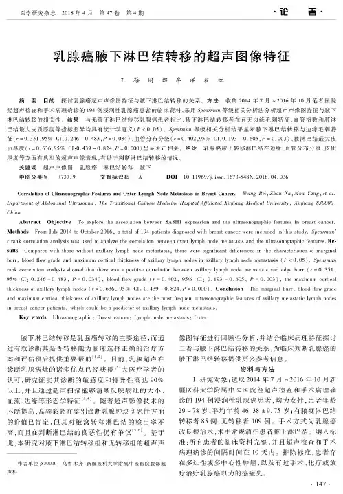
医学研究杂志2018年4月第47卷第4期• #-•乳腺癌腋下淋巴结转移的超声图像特征王蓓周娜牟洋翟虹摘要目的探讨乳腺癌超声声像图特征与腋下淋巴结转移的关系。
方法收集2014年7月?2016年10月笔者医院经超声检查和手术病理确诊的1'4例浸润性乳腺癌患者的临床资料,采用等级相关分析法分析超声声像图特征与腋下淋巴结转移的相关性。
结果与无腋下淋巴结转移乳腺癌患者相比,腋下淋巴结转移者在有无边缘毛刺特征、血管指数和腋淋巴结最大皮质厚度等指标差异均具有统计学意义(! <0.05)。
等级相关分析结果显示腋下淋巴结转移与边缘毛刺特征(r = 0.351,95[ ZI:0. 246 〜0.483,! = 0.034)、血管分布分级(r = 0.402,95[ ZI:0. 193 〜0.605,! = 0.003)、腋淋巴结最大皮质厚度(3 = 0.636,95[〔1:0.439〜0.824,!=0.000)呈显著正相关。
结论乳腺癌腋下转移淋巴结在边缘、血管分布分级、皮质厚度等方面有典型的超声声像表现,有助于判断淋巴结转移的情况。
关键词超声声像图乳腺癌淋巴结转移腋下中图分类号R737.9 文献标识码 A DOI10. 11969/j. issn. 1673-548X. 2018. 04. 036C o r r e la tio n o f U ltr a s o n o g r a p h ic F e a tu re s a n d O x te r L y m p h N o d e M e t^s t^s is in B r e a s t C a n c e r. W ang B e i,ZD epartm ent o f A bdo m in a l U ltra sou n d,The T raditional Chinese M edicine H ospital A ffiliated X in jia ng M edical U niversity,X in jia ng830000,C hinaAbstract Objective To explore the association between SASH1 expression and the ultrasonographic featiares in breast cancer. Methods From July 2014 to October 2016,atotal of 194 patients diagnosed with breast cancer were included in this study. S pea rm a n's rank correlation a nalysis was used to analyze the correlation betw^een oxter lymph node metastasis and the ultrasonographic featiures. Results Compared with those without axillary lymph node metastasis,there were significant diferences in the characteristics of marginal burr,blood flowgrade and maximum cortical thickness of axillary lymph nodes in axillary lymph node metastasis $!< 0. 05 ) .Spearm an rank correlation analysis showed that there was a positive correlation between axillary lymph node 95[ CI: 0. 246 - 0. 483,! = 0. 034 ),blood flow grade ( r = 0. 402,95[ CI: 0. 193 - 0. 605,! = 0. 003 ),the maximum cortical thickness of axillar lymph nodes ( r = 0.636,95% CI:0.439 -0.824,! = 0.000). Conclusion The marginal burr,blood flow grade and maximum cortical t hickness of axillary lymph nodes are the most frequent ultrasonographic features of axillary metastatic lymph nodes in breast cancer patients,which could be a predictor of axillar lymph node metastasis.Key words Ultrasonographic; Breast cancer;Lymph node metastasis;Oxter腋下淋巴结转移是乳腺癌转移的主要途径,而通 过有效诊断其是否转移能为临床选择正确的治疗方案和评估预后提供重要帮助[1,2]。

冰川下的生物对氧气的需求英文回答:Glaciers are icy bodies that form from the accumulation of snow over many years. They are found in polar regions, high mountain ranges, and even in some lower latitude areas. These frozen landscapes are home to a variety of organisms, both visible and microscopic. However, the livingconditions beneath glaciers are extremely challenging, and the organisms that inhabit these environments have adaptedto survive in harsh conditions.One of the key factors that affects the survival of organisms beneath glaciers is the availability of oxygen. Oxygen is essential for the respiration process, which provides energy for living organisms. However, the amountof oxygen dissolved in water decreases as the temperature drops. This means that the organisms living beneathglaciers have to cope with lower levels of oxygen comparedto those in other aquatic environments.To overcome this challenge, some organisms have developed unique physiological adaptations. For example, certain species of bacteria that live beneath glaciers can use alternative respiratory pathways that do not rely on oxygen. These bacteria are capable of carrying out anaerobic respiration, which allows them to obtain energy without the need for oxygen. This adaptation enables them to survive in oxygen-depleted environments.Another example of adaptation to low oxygen levels is seen in the invertebrates that inhabit the subglacial environment. These organisms have evolved specialized respiratory systems that maximize oxygen uptake. For instance, some species of midge larvae have elongated respiratory tubes that extend above the water surface, allowing them to access oxygen-rich air. These larvae are often referred to as "glacier worms" due to their ability to survive in such extreme conditions.In addition to physiological adaptations, organisms beneath glaciers also rely on other strategies to obtainoxygen. For instance, the movement of water within the glacier can create pockets of oxygen-rich water, providinga source of oxygen for the organisms. Some organisms may also actively migrate towards areas with higher oxygen concentrations, utilizing their mobility to seek out more favorable conditions.In conclusion, the organisms living beneath glaciers have adapted to cope with the low levels of oxygen in these environments. They have developed physiological adaptations, such as alternative respiratory pathways and specialized respiratory systems, to obtain energy and survive inoxygen-depleted conditions. The ability to thrive in such extreme environments showcases the remarkable resilienceand adaptability of these organisms.中文回答:冰川是多年积雪的冰体形成的。
氨基修饰β-环糊精衍生物水相仿生催化不对称Michael加成反应朱庆英;沈海民;杨祖金;纪红兵【期刊名称】《催化学报》【年(卷),期】2016(037)008【摘要】在不对称 Michael加成反应中,有机小分子如伯胺、吡咯烷类衍生物、(硫)脲类、手性方酰胺、联萘类、奎宁类、手性膦、离子液体和肽类等是目前使用的主要催化剂,如果能避免或少量使用有机溶剂,则更符合“绿色化学”的环境友好发展方向.β-环糊精的内腔疏水,而外部亲水,可以类似酶分子结合有机反应物,在水相体系进行催化反应.当β-环糊精分子上连接催化部位或结合部位时,能产生更优异的包结底物和诱导对映选择性的能力.目前基于β-环糊精衍生物构筑人工类酶催化剂用于不对称 Michael加成反应的报道较少.本文通过亲核取代反应将氨基类有机小分子与单(6-O-p-甲苯磺酰基)-β-环糊精结合,得到9个氨基修饰β-环糊精衍生物CD-1–CD-9(收率在24.2%–64.9%,分子结构通过1H NMR,13C NMR和 ESI-MS 表征确认),并用于室温水相体系不对称Michael加成的仿生催化反应,以期获得较好的催化反应活性和对映选择性.通过设计不同β-环糊精衍生物的修饰基团结构、改变反应介质pH值和反应底物结构,分析了Michael加成反应体系产物产率和对映选择性的变化,采用2D-1H ROESY NMR、紫外吸收光谱、红外光谱和和量子化学计算,分析了β-环糊精衍生物和反应底物分子的包结状态,探究了反应过程机理.结果显示,在该水相体系中进行的不对称Michael加成反应产物产率和对映体过量值(ee值)受修饰基团结构、反应介质pH值和底物结构影响较大.当反应介质pH 值低于6.0时,由于氨基分子被质子化而失去催化活性;当 pH值为7.5时,获得中等水平的对映选择性,通过量子化学在 ONIOM (B3LYP/6-31G(d):PM3)水平上的优化计算发现,底物分子与β-环糊精衍生物的包结可以出现两种形式:当底物分子的活性部位接近β-环糊精衍生物小口端的修饰基团时,产生分子内催化,诱导反应产生较好的对映选择性;当底物分子的活性部位远离β-环糊精衍生物小口端的修饰基团时,产生分子间催化,几乎没有对映选择性,而这两种情况同时存在.当底物分子以较大的空间位阻与β-环糊精疏水性空腔结合时,产生较好的对映选择性,邻位取代的2-硝基-β-硝基苯乙烯比对位取代的4-硝基-β-硝基苯乙烯 ee值更高,通过量子化学优化计算证实空间位阻效应.应用2-金刚烷酮与β-环糊精衍生物空腔形成竞争性的包结反应实验,产物产率和ee值都下降,说明β-环糊精衍生物的疏水性空腔是产生不对称诱导和催化活性不可或缺的部分,底物分子与β-环糊精衍生物的包结过程通过2D-1H ROESY NMR和紫外吸收图谱获得确认.其中L-2-氨甲基吡咯烷修饰β-环糊精 CD-1表现出较好的反应对映选择性,在溶剂(pH =7.5,0.5 mol/L CH3COONa-HCl)2 mL,环己酮2 mmol,2-硝基-β-硝基苯乙烯0.2 mmol,CD-1用量0.04 mmol,25°C反应96.0 h的条件下,环己酮与2-硝基-β-硝基苯乙烯Michael加成产物的 ee值达71%,产率为47%.该反应过程在β-环糊精衍生物的疏水性空腔内进行,修饰基团L-2-氨甲基吡咯烷与环己酮形成烯胺的催化反应.%Nineβ‐cyclodextrin derivatives containing an amino group were synthesized via nucleophilic sub‐stitution from mono(6‐O‐p‐tolylsulfonyl)‐β‐cyclodextrin and used in asymmetric biomimetic Mi‐chael addition reactions in water at room temperature. The mechanism responsible for the moder‐ate activity and enantioselectivity of the β‐cyclodextrin derivatives was explored using nuclear magnetic resonance spectroscopy, namely 2D 1H rotating‐frame overhauser effect spectr oscopy (ROESY), ultraviolet absorption spectroscopy, and quantum chemical calculations,which provide a useful technique for investigating the formation of inclusion complexes. The effects of the pH of the reaction medium, theβ‐cyclodextrin derivative dosage, the structure of the modifying amino group, and various substrates on the yield and enantioselectivity were investigated. The results indicated that these factors had an important effect on the enantiomeric excess (ee) in the reaction system. Experiments using a competitor for inclusion complex formation showed that a hydrophobic cavity is necessary for enantioselective Michael addition. A comparison of the reactions using 4‐nitro‐β‐nitrostyrene and 2‐nitro‐β‐nitrostyrene showed that steric hindrance im proved the enan‐tioselectivity. This was verified by the optimized geometries obtained from quantum chemical cal‐culations. An ee of 71%was obtained in the asymmetric Michael addition of cyclohexanone and 2‐nitro‐β‐nitrostyrene, using (S)‐2‐aminomethylpyrr olidine‐modified β‐CD as the catalyst, in an aqueous buffer solution, i.e., CH3COONa‐HCl (pH 7.5).【总页数】8页(P1227-1234)【作者】朱庆英;沈海民;杨祖金;纪红兵【作者单位】中山大学化学与化学工程学院化工系,广东广州 510275;浙江工业大学化学工程学院,浙江杭州 310014;中山大学化学与化学工程学院化工系,广东广州 510275;中山大学化学与化学工程学院化工系,广东广州 510275【正文语种】中文【相关文献】1.MacMillan催化剂水相不对称催化Aldol反应 [J], 黄勤安2.一种新型双亲性有机小分子催化剂在水相体系中催化环己酮与硝基烯烃直接不对称Michael加成反应 [J], 魏建伟;郭文岗;张博宇;刘;杜欣;李灿3.手性硫脲叔胺催化不对称Michael加成反应合成α,α-双取代芳基氨基酸前体 [J], 陈麟;周国川4.L-氨基酸衍生物修饰的Ru/γ-Al2 O3催化芳香酮不对称加氢研究 [J], 蒋和雁;陈华5.环糊精衍生物制备及催化水相碳-碳交联偶合反应 [J], 郭旭明;王露;周兴龙;张佳楠;邬峰因版权原因,仅展示原文概要,查看原文内容请购买。
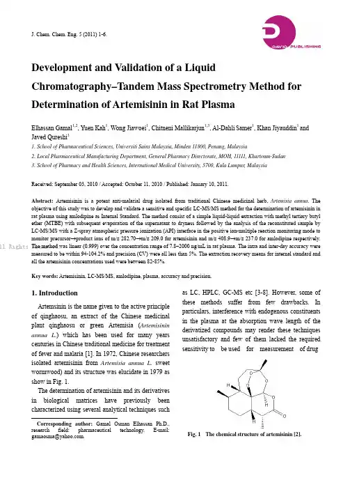
J. Chem. Chem. Eng. 5 (2011) 1-6.Development and Validation of a LiquidChromatography–Tandem Mass Spectrometry Method for Determination of Artemisinin in Rat PlasmaElhassan Gamal1,2, Yuen Kah1, Wong Jiawoei1, Chitneni Mallikarjun1,3, Al-Dahli Samer1, Khan Jiyauddin1 and Javed Qureshi31. School of Pharmaceutical Sciences, Universiti Sains Malaysia, Minden 11800, Penang, Malaysia2. Local Pharmaceutical Manufacturing Department, General Pharmacy Directorate, MOH, 11111, Khartoum-Sudan3. School of Pharmacy and Health Sciences, International Medical University, 5700, Kula Lumpur, MalaysiaReceived: September 03, 2010 / Accepted: October 11, 2010 / Published: January 10, 2011.Abstract: Artemisinin is a potent anti-malarial drug isolated from traditional Chinese medicinal herb, Artemisia annua. The objective of this study was to develop and validate a sensitive and specific LC-MS/MS method for the determination of artemisinin in rat plasma using amlodipine as Internal Standard. The method consist of a simple liquid-liquid extraction with methyl tertiary butyl ether (MTBE) with subsequent evaporation of the supernatant to dryness followed by the analysis of the reconstituted sample by LC-MS/MS with a Z-spray atmospheric pressure ionization (API) interface in the positive ion-multiple reaction monitoring mode to monitor precursor→product ions of m/z 282.70→m/z 209.0 for artemisinin and m/z 408.9→m/z 237.0 for amlodipine respectively. The method was linear (0.999) over the concentration range of 7.8–2000 ng/mL in rat plasma. The intra and inter-day accuracy were measured to be within 94-104.2% and precision (CV) were all less than 5%. The extraction recovery means for internal standard and all the artemisinin concentrations used were between 82-85%.Key words: Artemisinin, LC-MS/MS, amlodipine, plasma, accuracy and precision.1. IntroductionArtemsinin is the name given to the active principle of qinghaosu, an extract of the Chinese medicinal plant qinghaosu or green Artemisia (Artemisinin annua L.) which has been used for many years centuries in Chinese traditional medicine for treatment of fever and malaria [1]. In 1972, Chinese researchers isolated artemisinin from Artemisia annua L. sweet wormwood) and its structure was elucidate in 1979 as show in Fig. 1.The determination of artemisinin and its derivatives in biological matrices have previously been characterized using several analytical techniques suchCorresponding author: Gamal Osman Elhassan Ph.D., research field: pharmaceutical technology. E-mail: ******************.as LC, HPLC, GC-MS etc [3-8]. However, some of these methods suffer from few drawbacks. In particulars, interference with endogenous constituents in the plasma at the absorption wave length of the derivatized compounds may render these techniques unsatisfactory and few of them lacked the required sensitivity to be used for measurement of drugFig. 1 The chemical structure of artemisinin [2].ll Rights Reserved.Development and Validation of a Liquid Chromatography–Tandem Mass Spectrometry Method forDetermination of Artemisinin in Rat Plasma2concentration in blood sample obtained from clinical investigation [9].To increase the specificity and sensitivity of HPLC-UV method, some workers combined it with a mass spectrometry (MS) and the total system is described as LC-MS technique [10, 11]. The development of LC-tandem mass spectrometry (LC-MS/MS) has made a more specific and sensitive analysis of artemisinin and its derivatives possible [12, 13]. The objective of this study was to develop a sensitive and specific LC-MS/MS method for the determination of artemisinin in rat plasma by simple liquid-liquid extraction procedure.2. Materials and Methods2.1 MaterialsArtemisinin was purchased from Kunming Pharmaceutical Corporation (Kunming, China). Amlodipine was obtained from Sigma Chemical (Louis, USA). Acetonitrile (ACN), formic acid and methyl tertiary butyl ether (MTBE) were purchased from J.T Baker (USA).3. Methods3.1 Instrumentation and ConditionsThe instrumentation comprised of Quattro-micro tandem mass spectrometer with Z-spray atomospheric pressure ionization (API) source (Micromass, Manchester, UK) using electrospray ionization (ESI) operated at positive mode. Chromatography was performed on an Alliance 2,695 separation module (Waters, M.A, USA). The delivery system consisted of an autosampler and a column heater. The chromatographic separation was obtained using an X Terra MS C8 encapped (5 μm) (150 × 2.1 mm) analytical column (Water, USA).3.2 Sample PreparationA 250 μL aliquot of plasma was pipetted into a screw-capped culture tube, followed by 100 μL of internal standard solution (50 ng/mL). To each tube, 5 mL (MTBE) extraction solvent was then added and the mixture was vortexed for 2.5 minutes followed by centrifuging for 15 minutes at 3,500 rpm. The upper layer was transferred to a reactive vial and dried under nitrogen flow at 40 °C. The residue was then reconstituted with 250 μL of mobile phase and 20 μL was injected into the LC-MS/MS system.3.3 Assay ValidationCalibration curve at a concentration range of 7.8–2,000 ng/mL were constructed by spiking blank human plasma with a known amount of artemisinin. Plasma sample spiked with artemisinin at these concentrations 7.8, 62.5, 250, 2,000 ng/mL were used to determine the within and between-day accuracy and precision. For within-day accuracy and precision, replicates analysis (n = 6) for each concentration were performed in a single day. For between-day evaluation, analysis was carried out with a single sample of each concentration daily over 6 days, with calibration curve constructed on each day of analysis. The extraction recovery of artemisinin was estimated by comparing the peak height obtained after extraction of the samples from plasma with that of aqueous artemisinin solution of the corresponding concentration.4. Results and DiscussionBoth electrospray (TIS) and atmospheric pressure chemical ionisation (APCI) methods have been reported previously for the quantification of artemisinin derivatives in biological fluids [11, 12, 14-16]. According to the previously reported methods TIS was found to be superior to APCI for the quantification of artesunate and dihydroartemisinin (DHA) mainly because of improved linearity [16]. Therefore in this method electrospray ionization was used. When artemisinin and amlodipine were injected directly into the mass spectrometer along with mobile phase in the positive mode, the protonated molecules of artemisinin and amlodipine were set as precursorll Rights Reserved.Development and Validation of a Liquid Chromatography–Tandem Mass Spectrometry Method forDetermination of Artemisinin in Rat Plasma3(a)(b)Fig. 2 (a) Positive-ionization electrospray mass spectra of precursor ion for artemisinin; (b) Positive-ionization electrospray mass spectra of product ion for artemisinin.ions with m/z of 282.7 and 408.7, respectively. The product ion that gave the highest intensity was m/z of 209.0 for artemisinin and 237.7 for amlodipine. Fig 2(a) shows the spectra precursor ion, 2(b) production for artemisinin.Artemisinin and amlodipine have retention time of approximately 6.9 and 1.65 minutes, respectively (Fig.3). The peak was well resolved and free from interference from endogenous compounds in rat plasma (Fig. 4).ll Rights Reserved.Development and Validation of a Liquid Chromatography–Tandem Mass Spectrometry Method forDetermination of Artemisinin in Rat Plasma4Fig. 3 Plasma spiked with 500 ng/ml artemisinin and amlodipine 50 ng/mL.Fig. 4 Chromatograms for analysis of artemisinin in plasma (Rat blank plasma).Calibration curve was linear over the entire range of calibration curves with a mean correlation coefficient greater than 0.9995 (Fig. 5).The limit of quantification (LOQ) of the assay method was 7.8 ng/mL being the lowest concentration used to construct the calibration curve whereas the limit of detection (LOD) was 3.9 ng/mL at a signal to noise ratio of 3. The validation data demonstrated a good precision, accuracy and recovery. The extraction recovery means for internal standard and all artemisinin concentrations used were 75-85% (Table 1). The within-day and between-day accuracy and precision values are given in Table 2.Neither artemisinin nor the internal standard producedll Rights Reserved.Development and Validation of a Liquid Chromatography–Tandem Mass Spectrometry Method forDetermination of Artemisinin in Rat Plasma5Fig. 5 Mean calibration curve of artemisinin (ng/mL).Table 1 Extraction recovery.Concentration (ng/mL) Mean recovery (%) CV (%)7.81 75.081.5062.50 82.161.94250.00 82.03 2.072000.00 85.23 1.48Table 2 Within-day and between-day precision andaccuracy.Added (ng/mL)Within-day Between-day Accuracy (%) C.V (%) Accuracy (%) C.V (%)7.81 96.00 4.60 104.11 2.30 62.50 98.10 1.60 94.10 2.20 250.00 98.10 1.50 98.10 1.60 2000.00 96.10 2.50 97.10 1.80any detectable carry-over after three injections of upper limit of quantification. Blank rat plasma showed no interference with artemisinin. Interfering signals from blank plasma contributed less than 20% of the artemisinin signal at LOQ. There was no interference of artemisinin on the internal standard or vice versa. A small enhancement for artemisinin and the internal standard could be detected when references in neat injection solvent were compared with references in extracted blank biological matrix. The normalized matrix effects (artemisinin/internal standard) were close to 1 with a low variation in accordance with international guidelines. Post-column infusion experiments confirmed the absence of regions with severe matrix effects (i.e., no sharp drops or increases in the response) for blank human plasma extracted with the developed method.Xing et al. used artmether as an internal standard for the analysis of artemisinin [17]while for the analysis of artemisinin derivatives; artemisinin was used as internal standard [14]. In the present study amlodipine was found to be suitable because it could be separated chromatographically, ionized and fragmented under the conditions that optimized the intensity of artemisinin peak (Fig. 3).The analysis of artemisinin and its derivatives with mass spectrometry are most often performed with a different mode of ionization. Xing et al. used ESI inletin the positive ion-multiple reaction monitoring mode which relatively producing a higher sensitivity than in the SIM mode. Therefore, the mass spectrometry was operated at positive ion-MRM mode.4. ConclusionThe LC-MS/MS method described in this work is suitable for the determination of artemisinin in plasma. The assay procedure is simple with a relatively shortll Rights Reserved.Development and Validation of a Liquid Chromatography–Tandem Mass Spectrometry Method forDetermination of Artemisinin in Rat Plasma6retention time allowing sufficient sample to beprocessed to be applied to pharmacokinetic and bioavailability studies of artemisinin. The accuracy and precision of the assay method, as well as the recovery of extraction procedure were found to be satisfactory.References[1] D.L. Klayman, Qinghasou (Artemisinin): An antimalaria drug from China, Science 228 (1985) 1049-1055.[2] X.D. Luo, C.C. Shen, The chemistry, pharmacology andclinical applications of Qinghaosu (artemisinin) and it’sderivatives, Med. Res. Rev. 7 (1987) 29-52.[3] K.T. Batty, M. Ashton, K.F. Llett, G . Edwards, T.M. Davis,Selective high-performance liquid chromatography ofartesunate and α-and β-dihydroartemisinin in patients withfalciparum malaria, J. Chromatog. B 677 (2-3) (1996)345-350.[4] J. Karbwang, K. Na-Bangchang, P. Molunto, V . Banmairuroi, Determination of artemisinin and its majormetabolite, dihydroartemisinin, in plasma usinghigh-performance liquid chromatography withelectrochemical detector, J. Chromatog. B 7 (1-2) (1997)259-265.[5] K.L. Chan, K.H. Yuen, H. Takayanki, S. Jinandasa, K.K. Peh, Polymorphism of artemisinin from Artemisia annua,Phytochemistry 46 (7) (1997) 1209-1214.[6] G .Q. Li, T.O. Peggins, L.L. Fleckenstein, K. Masonic,M.H. Heiffles, T.G . Brewer, The pharmacokinetics andbiovailability of dihydroartemisinin, arteether, artemether,artesunic acid and artelinic acid in rats, J. Pharm.Pharmacol 5 (1998) 173-182.[7] B.A. Avery, K.K. Venkatesh, M.A. Avery, Rapid determination of artemisinin and related analogues usinghigh-perfomance liquid chromatography and anevaporative light scattering detector, J. Chromat. B 730 (1)(1999) 71-80.[8] S.S. Mohamed, S.A. Khalid, S.A. Ward, T.S.M. Wan,H.P.O. Tang, M. Zheng, R.K. Haynes, G . Edwards,Simultaneous determination of artemether and its majormetabolite dihydroartemisinin in plasma by gaschromatography-mass spectrometry-selected ionmonitoring, J. Chromat. B 731(1999) 251-260.[9] K.T. Batty, M. Ashton, K.F. Llett, G . Edward, T.M. Davis,The pharmacokinetics of artemisinin (ART) and artesunate (ARTS) in healthy volunteers, Am J. Trop Med. Hyg. 58(2) (1998) 125-126.[10] C. Souppart, N. Gouducheau, N. Sandenan, F. Richard,Development and validation of a high-performance liquid chromatography-mass spectrometry assay for the determination of artemisinin and its metabolite dihydraartemisinin in human plasma, J. Chromat. B 774(2002) 195-203.[11] H. Naik, D.J. Murry, L.E. Kirsch, L. Fleckenstein,Development and validation of high-performance liquid chromatography-mass spectroscopy assay for determination of artesunate and dihydrroartemisinin in human plasma, J. Chromat. B 816 (1-2) (2005) 233-242. [12] J. Xing, H. Yan, S. Zhang, G . Ren, Y . Gao, A high-performance liquid chromatography/tandem mass spectrometry method for the determination of artemisinin in rat plasma, Rapid Commun in Mass Spectro. 20 (9) (2006) 1463-1468. [13] J. Xing, H.X. Yan, R.L. Wang, L.F. Zhang, S.Q. Zhang,Liquid chromatography-tandem mass spectrometry assay for the quantitation of β-dihydroartemisinin in rat plasma, J. Chromat. B 852 (1-2) (2007) 202-207. [14] M. Rajanikanth, K.P. Madhusudanan, R.C. Gupta, An HPLC-MS method for simultaneous estimation of alpha, beta-arteether and its metabolite dihydroartemisinin, in rat plasma for application to pharmacokinetic study, J Biomed. Chromat. 17 (7) (2003) 440-446. [15] Y . Gu, Q. Li, M.V . Elendez, P. Weina, Comparison of HPLC with electrochemical detection and LC–MS/for the separation and validation of artesunate and dihydroartemisinin in animal and human plasma, J. Chromatogr B 867 (2008) 213-218. [16] W. Hanpithakpong, B. Kamanikom, A.M. Dondorp, P.Singhasivanon, N.J. White, N.P. Day, N. Lindegardh, A liquid chromatographic-tandem mass spectrometric method for determination of artesunate and its metabolite dihydroartemisinin in human plasma, J. Chromatogr. B 876 (2008) 61-68. [17] Y . Xing, H. Yan, S. Zhang, G . Ren, Y . Gao, A high-performance liquid chromatography/tandem mass spectrometry method for the determination of artemisinin rat plasma, Rapid Communication in Mass Spectrometry 20 (9) (2006) 1463-1468.ll Rights Reserved.。
a rXiv:as tr o-ph/31292v11Oct23Recycling intergalactic and interstellar matter IAU Symposium Series,Vol.217,2004Pierre-Alain Duc,Jonathan Braine and Elias Brinks,eds.Metal Abundances and Kinematics of the Ly-αabsorbers Sergei A.Levshakov Department of Theoretical Astrophysics,Ioffe Physico-Technical Institute,Politekhnicheskaya Str.26,194051St.Petersburg,Russia Abstract.Both high resolution spectra of QSOs observed at the 8-10m telescopes and advanced methods of data analysis are crucial for accu-rate measurements of the chemical composition and physical parameters of the intervening clouds.An overview of our recent results obtained with the Monte Carlo inversion (MCI)procedure is presented.This includes:(1)variations of the shape of the local background ionizing continuum in the 1–5Ryd range at redshift z ∼2.8−3.0;(2)an inverse correlation between the measured metallicity,[C/H],and the absorber line-of-sight linear size,L ;(3)a functional dependence between the line-of-sight ve-locity dispersion,σv ,and L .1.Introduction A study of quasar (QSO)absorption-line spectra is generally recognized as the most reliable technique for inferring the physical and dynamical state of gas in the intervening absorption clouds at high redshifts,z ∼>2.Of particular interest are the measurements of metallic absorptions in the optically thin diffuse clouds with neutral hydrogen column densities N (H i )∼<3×1017cm −2.These systems will be called as ‘Ly-αabsorbers’(LAA)to distinguish from the damped Ly-αabsorption systems (DLA)which show much higher column densities,N (H i )∼>2×1020cm −2.The latter are believed to arise in the galactic disks (e.g.,Wolfe et al.1995),whereas the former may be physically related to the external (∼10-100kpc-scale)regions of galaxies (e.g.,Chen et al.2001).Thus the measurements of the LAAs can provide fundamental insights into conditions prevailing in the galactic environments (external halos)in the early universe.Since these regions are mainly photoionized by the local metagalactic UV radiation,the ionization states of the LAAs are sensitive to the spectral shape of the background radiation in the 1-5Ryd range.The spectral energy distribution in the metagalactic ionizing background is defined in turn by the QSO continua filtered through the quasar environments and the IGM.Two implications of the LAA analysis –the metal content of the external halos and the spectral shape of the local UV background –are,therefore,tightly coupled.To clarify the mechanism of the metal enrichment,accurate measurements of the metal abundances in the LAAs are required.The main problem here is how to account for the ionization correction.In general,the contribution to the line intensity Iλwithin the profile comes from all volume elements distributedalong the line of sight and having the same radial velocity.If the gas number12S.A.Levshakovdensity,n H,varies from point to point,then the intensity Iλis caused by a superposition of different ionization states.Recently,we have developed a method called‘Monte Carlo inversion’(MCI) to recover the physical parameters of the LAAs assuming that the absorb-ing cloud is a continuous region withfluctuating density and velocityfields (Levshakov et al.2000,hereafter LAK).The MCI was applied to high qual-ity QSO spectra obtained with the VLT/UVES,Keck/HIRES,and HST/STIS (Levshakov et al.2002;Levshakov et al.2003a,b,c,d,e).The results of these studies are briefly reviewed in this contribution.2.The MCI procedureThe layout of the MCI procedure is the following.We assume that the metal abundances within the absorber are constant,the gas is optically thin for the ionizing UV radiation,and the gas is in thermal and ionization equilibrium. The radial velocity v(x)and the total hydrogen density n H(x)along the line of sight are considered as two randomfields which are represented by their sampled values at equally spaced intervals∆x,i.e.by the vectors{v1,...,v k} and{n1,...,n k}with k large enough(∼150−200)to describe the narrowest components of the complex spectral lines.The radial velocity is assumed to be normal distributed with the dispersionσv,whereas the gas density is log-normal distributed with the mean n0and the dispersionσy(y=n H/n0).The stochasticfields are approximated by the Markovian processes.The accuracy of the restoring procedure depends on the number of different ions in different ionization stages involved in the analysis of a given LAA.A set of thefitting parameters in the least-squares minimization of the objective function(Eqs.[29]and[30]in LAK)includesσv andσy along with the total hydrogen column density N H,the mean ionization parameter U0,and the metal abundances Z a for a elements observed in the LAA.With these parameters we can further calculate the mean gas number density n0,the column densities for different species N a,the mean kinetic temperature T kin,and the line-of-sight size L=N H/n0of the absorber(note that n0and,correspondingly,L scales with the intensity of the local background radiationfield).We start calculations assuming some standard ionizing spectrum[e.g.,power law,Mathews&Ferland(1987),or Haardt&Madau(1996,hereafter HM)]and compute the fractional ionizations and the kinetic temperatures at each point x along the sightline with the photoionization code CLOUDY(Ferland1997). To optimize the patterns of{v i}and{n i}and to estimate simultaneously the fitting parameters,the simulated annealing algorithm with Tsallis acceptance rule and an adaptive annealing temperature choice are used.If thefitting with the standard spectrum is impossible,its shape is adjusted using the procedure based on the experimental design technique(Levshakov et al.2003e).3.The spectral shape of the ionizing continuumIn practice,the shape of the ionizing spectrum can be estimated in cases when the value of N(H i)is measured accurately and the absorption system containsAbundances and Kinematics of the Ly-αabsorbers3Figure1.A typical metagalactic ionizing spectrum at redshift z∼3(the dotted curve)modeled by Haardt&Madau(1996),and its modifi-cation(the solid curve)required to match the absorption lines observedin a LAA at z=2.82toward HE0940–1050(Levshakov et al.2003e).The spectrum is normalized so that Jν(hν=1Ryd)=1.The emissionbump at3Ryd is caused by reemission of He ii Lyαand two-photoncontinuum emission from intergalactic clouds.unsaturated lines of at least C ii–C iv and Si ii–Si iv,otherwise the system is not sensitive to thefine tuning of the continuum shape.We estimated the spectral shape for the LAAs at z=2.82(H i,C ii,C iii, Si iii,C iv,Si iv)toward HE0940–1050;z=2.7711(H i,C ii,Si ii,C iii,N iii, Si iii,C iv,Si iv,O vi),and z=2.94(H i,C ii,Si ii,C iii,Si iii,C iv,Si iv) toward Q1157+3143(Levshakov et al.2003e).All three recovered spectra of ionizing radiation show common features:a bump at E=3Ryd,which is more pronounced comparing to the model mean intergalactic UV spectra at z=3like that of Haardt&Madau(1996),and a sharp break just after the bump–also at variance with the model predicting a smeared out break at E=4Ryd due to ionization of He ii.An example of ionizing background estimated for the z=2.82absorption system toward HE0940–1050is shown in Fig.1.This spectral shape rules out a considerable galactic contribution to the QSO dominated UV ionizing background at z∼3. The recovered UV spectrum can be well explained in the scenario of the delayed re-ionization of He ii(Reimers et al.1997).In this case the sharp break at E=3Ryd occurs due to strong resonant scattering of QSO radiation in metal4S.A.LevshakovFigure2.Carbon abundances[C/H]plotted against the logarithmiclinear size L of the absorber estimated by the MCI procedure(Lev-shakov et al.2002;2003a,b,c,e).[C/H]decreases with increasing Lreflecting,probably,the dilution of metals within galactic halos causedby the mass transport processes.and He ii Lyman series lines whereas a part of the absorbed photons re-emitted by the intergalactic gas in the He ii Lyαand two-photon continuum emission increases the amplitude of the bump at3Ryd.Our results also indicate that the re-ionization of He ii has not been yet completed by z=2.77.This results is in line with recent observations of the He ii Ly-αforest by Shull et al.(2003) who claim that‘the ionizing background is highly variable throughout the IGM’at z∼2.8.4.‘[C/H]−L’and‘σv−N H L’relationsThe analyzed LAAs show that they are a heterogeneous population that is formed by at least three groups of absorbers:(1)extended metal-poor(Z<0.1Z⊙)gas halos of distant galaxies;(2)gas in dwarf galaxies(0.1Z⊙<Z∼<0.3Z⊙);and (3)metal-enriched gas(Z∼>0.5Z⊙)arising from the inner galactic regions and condensing into the clouds within the hot galactic halo(high redshift analogs to the Galactic high velocity clouds,HVC).Abundances and Kinematics of the Ly-αabsorbers5Figure3.Plot of the line of sight velocity dispersion log(σv)vs.log(N H L)for the same sample of the LAAs shown in Fig.2.Thedashed line corresponds to the relation log(σv)∝0.5log(N H L)ex-pected for the virialized systems.Open squares represent HVC-likeclouds with L∼<1kpc.Figure2shows a plot of the measured carbon abundances[C/H]1versus logarithmic sizes of the studied systems.Systematically higher abundances are seen in compact systems.This tendency reflects,probably,the dilution of met-als within galactic halos caused by the mass transport processes(like diffu-sion,turbulent mixing,galactic rotation,shear,and etc.).Metals are,probably, transported into the halo in form of small dense clouds carried out by wind or jets.In some cases we directly observe such blobs.For instance,the LAAs at z=1.385([C/H]≃−0.3,L≃1.7−2.5kpc)and at z=1.667([C/H]≃−0.5, L≃1kpc)toward HE0515–4414as well as that at z=2.966([C/H]≃−0.4, L≃100pc)toward Q0347–3819are embedded in extremely metal-poor halos with[C/H]<−2(Levshakov et al.2003b,c).If LAAs are formed in gas clouds gravitationally bound with intervening galaxies,their internal kinematics should be closely related to the total masses of the host galaxies.Wefind a correlation between the absorber’s linear size L and its line-of-sight velocity dispersionσv.The virial theorem states:σ2v∝M/L∝n0L2=N H L.Assuming that the gas systems are in quasi-equilibrium,6S.A.Levshakovone can expectσv∝(N H L)1/2.In Fig.3we plot the measured values ofσv versus the product of L and the total gas column density N H.It is seen that most systems with linear sizes L>1kpc lie along the line with the slope0.5. Taking into account that we know neither the impact parameters nor the halo density distributions,this result can be considered as a quite goodfit to the expected relation for the virialized systems.Hence we may conclude that most absorbers with L>1kpc are gravitationally bound with systems that appear to be in virial equilibrium at the cosmic time when the corresponding LAAs were formed.Acknowledgments.This work would not have been possible without the contribution of many individuals,including Irina Agafonova,Wilhelm Kegel, Miriam Centuri´o n,Paolo Molaro,Igor Mazets,Miroslava Dessauges-Zavadsky, Sandro D’Odorico,Dieter Reimers,Robert Baade,David Tytler,and Art Wolfe.I also appreciate support from the RFBR grant No.03-02-17522,and I am very grateful to the IAU for a travel grant.ReferencesChen,H.-W.,Lanzetta,K.M.,&Webb,J.K.2001,ApJ,556,158Ferland,G.J.1997,A Brief Introduction to Cloudy(Internal Rep.,;Lexington: Univ.Kentucky)Haardt,F.,&Madau,P.1996,ApJ,461,20[HM]Holweger,H.2001,in Solar and Galactic Composition,ed.R.F.Wimmer-Schweingruber,AIP Conf.Proceed..598,23Levshakov,S.A.,Agafonova,I.I.,&Kegel,W.H.2000,A&A,360,833[LAK] Levshakov,S.A.,Agafonova,I.I.,Centuri´o n,M.,&Mazets,I.E.2002,A&A, 383,813Levshakov,S.A.,Agafonova,I.I.,Centuri´o n,M.,&Molaro,P.2003a,A&A, 397,851Levshakov,S.A.,Agafonova,I.I.,D’Odorico,S.,Wolfe,A.M.,&Dessauges-Zavadsky,M.2003b,ApJ,582,596Levshakov,S.A.,Agafonova,I.I.,Reimers,D.,&Baade,R.2003c,A&A,404, 449Levshakov,S.A.,D’Odorico,S.,Agafonova,I.I.,&Dessauges-Zavadsky,M.2003d,A&A,in press,astro-ph/0310141Levshakov,S.A.,Agafonova,I.I.,Molaro,P.,Centuri´o n,M.,&Tytler,D.2003e,A&A,submittedMathews,W.G.,&Ferland,G.J.1987,ApJ,323,456Reimers,D.,K¨o hler,S.,Wisotzki,L.,Groote,D.,Rodriguez-Pascual,P.,& Wamsteker,W.1997,A&A,327,890Shull,J.M.,Tumlinson,J.,Giroux,M.L.,Kriss,G.A.,&Reimers,D.2003, ApJ,in press,astro-ph/0309625Wolfe,A.M.,Lanzetta,K.M.,Foltz,C.B.,&Chaffee,F.H.1995,ApJ,454, 698。

色谱柱膜厚英文The membrane thickness of a chromatography column is an important parameter that can greatly impact the separation efficiency and resolution of the chromatographic process. The membrane thickness refers to the distance between the inner surface of the column and the outer surface of the stationary phase. It is typically measured in micrometers (µm) or millimeters (mm).The membrane thickness directly affects the masstransfer kinetics and the overall performance of the chromatography column. A thicker membrane can result in longer diffusion paths for the analytes, leading to slower mass transfer and potentially lower resolution. On the other hand, a thinner membrane can allow for faster mass transfer but may also be more prone to mechanical damage.In addition to its effects on mass transfer, the membrane thickness also influences the pressure drop across the column. Thicker membranes can lead to higher pressure drops, which can affect the flow rate and the overall stability of the chromatographic system.It is important to note that the optimal membrane thickness for a chromatography column can vary depending on the specific application and the properties of the analytes being separated. Factors such as analyte size, diffusion coefficients, and the desired separation efficiency all play a role in determining the ideal membrane thickness.In summary, the membrane thickness of a chromatography column is a critical parameter that can significantly impact the performance of the separation process. Understanding the effects of membrane thickness and carefully selecting the appropriate membrane for a given application are essential for achieving the desired separation results.色谱柱的膜厚是影响色谱分离效率和分辨率的重要参数。
《丝胶靶向Akt1调控糖酵解及氧化应激保护STZ致损伤INS-1细胞》篇一一、引言随着糖尿病发病率的逐年攀升,研究胰岛素敏感度调节和β细胞损伤的机制对于防治糖尿病具有重要意义。
STZ(链脲佐菌素)诱导的INS-1细胞损伤模型是研究糖尿病发病机制及药物筛选的常用模型。
丝胶作为一种天然生物活性物质,具有多种生物功能,包括抗氧化、抗炎和促进细胞修复等。
本文旨在探讨丝胶靶向Akt1(蛋白激酶B)对糖酵解及氧化应激的影响,并分析其在STZ致损伤的INS-1细胞中的保护作用。
二、材料与方法2.1 材料实验所需材料包括:丝胶、STZ、INS-1细胞、相关试剂及仪器等。
2.2 方法(1)INS-1细胞培养及STZ处理:培养INS-1细胞,并给予不同浓度的STZ处理,建立细胞损伤模型。
(2)丝胶处理:将丝胶加入到STZ处理的INS-1细胞中,观察其对细胞的保护作用。
(3)Akt1活性检测:采用相关方法检测Akt1的活性变化。
(4)糖酵解及氧化应激指标检测:检测相关指标包括乳酸脱氢酶、丙二醛等。
(5)统计分析:采用SPSS软件进行数据分析,P<0.05为差异有统计学意义。
三、结果3.1 丝胶对STZ致损伤的INS-1细胞的保护作用实验结果显示,丝胶能够显著降低STZ对INS-1细胞的损伤程度,提高细胞存活率。
3.2 丝胶对Akt1活性的影响丝胶处理后,Akt1活性显著提高,表明丝胶可能通过激活Akt1发挥其保护作用。
3.3 丝胶对糖酵解及氧化应激的影响丝胶处理后,糖酵解相关指标如乳酸脱氢酶活性降低,氧化应激相关指标如丙二醛含量降低,表明丝胶能够调节糖酵解及氧化应激水平。
四、讨论4.1 丝胶保护INS-1细胞的机制丝胶通过激活Akt1,进而调控糖酵解及氧化应激,从而对STZ致损伤的INS-1细胞产生保护作用。
Akt1作为一种重要的信号分子,在细胞生存、增殖和凋亡等方面发挥重要作用。
丝胶可能通过与Akt1相互作用,激活其下游信号通路,从而发挥保护作用。
益生菌对阿尔茨海默病作用的研究进展发布时间:2021-12-14T06:08:15.523Z 来源:《中国结合医学杂志》2021年12期作者:宋鑫萍1,2,李盛钰2,金清1[导读] 阿尔茨海默病已成为威胁全球老年人生命健康的主要疾病之一,患者数量逐年攀升,其护理的经济成本高,给全球经济造成重大挑战。
近年来研究显示,益生菌在适量使用时作为有益于宿主健康的微生物,在防治阿尔茨海默病方面具有积极影响,其作用机制可能通过调节肠道菌群,影响神经免疫系统,调控神经活性物质以及代谢产物,通过肠-脑轴影响该病发生和发展。
宋鑫萍1,2,李盛钰2,金清11.延边大学农学院,吉林延吉 1330022.吉林省农业科学院农产品加工研究所,吉林长春 130033摘要:阿尔茨海默病已成为威胁全球老年人生命健康的主要疾病之一,患者数量逐年攀升,其护理的经济成本高,给全球经济造成重大挑战。
近年来研究显示,益生菌在适量使用时作为有益于宿主健康的微生物,在防治阿尔茨海默病方面具有积极影响,其作用机制可能通过调节肠道菌群,影响神经免疫系统,调控神经活性物质以及代谢产物,通过肠-脑轴影响该病发生和发展。
本文综述了近几年来国内外益生菌对阿尔茨海默病的作用进展,以及其预防和治疗阿尔茨海默病的潜在作用机制。
关键词:益生菌;阿尔茨海默病;肠道菌群;机制Recent Progress in Research on Probiotics Effect on Alzheimer’s DiseaseSONG Xinping1,2,LI Shengyu2,JI Qing1*(1.College of Agricultural, Yanbian University, Yanji 133002,China)(2.Institute of Agro-food Technology, Jilin Academy of Agricultural Sciences, Chanchun 130033, China)Abstract:Alzheimer’s disease has become one of the major diseases threatening the life and health of the global elderly. The number of patients is increasing year by year, and the economic cost of nursing is high, which poses a major challenge to the global economy. In recent years, studies have shown that probiotics, as microorganisms beneficial to the health of the host, have a positive impact on the prevention and treatment of Alzheimer’s disease. Its mechanism may be through regulating intestinal flora, affecting the nervous immune system, regulating the neuroactive substances and metabolites, and affecting the occurrence and development of the disease through thegut- brain axis. This paper reviews the progress of probiotics on Alzheimer’s disease at home and abroad in recent years, as well as its potential mechanism of prevention and treatment.Key words:probiotics; Alzheimer’s disease; gut microbiota; mechanism阿尔茨海默病(Alzheimer’s disease, AD),系中枢神经系统退行性疾病,属于老年期痴呆常见类型,临床特征主要包括:记忆力减退、认知功能障碍、行为改变、焦虑和抑郁等。
AFM-microRaman and nanoRaman TMIntroductionThe use of Raman microscopy has become animportant tool for the analysis of materials on themicron scale. The unique confocal and spatialresolution of the LabRAM series has enabled opticalfar field resolution to be pushed to its limits withoften sub-micron resolution achievable.The next step to material analysis on a smallerscale has been the combination of Ramanspectroscopic analysis with near field optics and anAtomic force microscope (AFM). The hybridRaman/AFM combination enables nanometrictopographical information to be coupled to chemical(spectroscopic) information. The unique designsdeveloped by HORIBA Jobin Yvon enable in-situRaman measurements to be made upon variousdifferent AFM units, and for the exploration of newand evolving techniques such as nanoRamanspectroscopy based on the TERS (tip enhancedRaman spectroscopy) effect.AFM image of nano-structures on a SiN sampleHORIBA Jobin Yvon offers both off-axis and on-axisAFM/Raman coupling to better match your sampleand analysis requirements.Off-axis and inverted on-axis configurations forAFM/Raman coupling showing the laser (blue) andRaman (pink) optical pathThe LabRAM-Nano Series is based on the provenLabRAM HR system providing unsurpassedperformance for classical Raman analysis. With theAFM coupling option, it becomes the platform ofchoice for AFM/Raman experiments. The off-axisgeometry offers large sample handling capabilitiesand is ideally suited for the analysis ofsemiconductor materials, wafers and more generallyopaque samples.For biological and life science applications, theLabRAM-Nano operates in inverted on-axisconfiguration with a confocal inverted Ramanmicroscope on top of which the AFM unit is directlymounted. This system is ideally suited for the studyof transparent biological samples such as singlecells, tissue samples and bio-polymers.In both systems, AFM and SNOM fluorescencemeasurements can be combined with Ramananalysis to provide a more completecharacterisation of sample chemistry andmorphology on the same area. Several AFMsystems from leading AFM manufacturers can beadapted on these two instruments. Please contactus to find out which one is best for you!AFM- microRaman dual analysisThe seamless integration of hardware and software of both systems onto the same platform enables fast and user-friendly operation of both systems at the same time. Furthermore, the AFM/Raman coupling does not compromise the individual capabilities of either system and the imaging modes of the AFM remain available (EFM, MFM, Tapping Mode, etc.)The operator has direct access to both the nanometric topography of a sample given by the AFM, and the chemical information from the micro-Raman measurement. An AFM image can berecorded as an initial survey map, in which regions of interest can be defined for further Raman analysis, using the same software.An example of such analysis is illustrated below by an AFM image of Carbon Nanotubes (CNTs) giving information on the CNTs’ length, diameters and aggregation state. A more detailed AFM image is then obtained in which Raman analysis can be performed.Carbon nanotubes AFM images with a gold-coated tip in contact mode. The diameter of the bundles of nanotubes is between 10 and 30 nm.NanoRaman for TERS experimentsSurface Enhance Raman Scattering (SERS) has long been used to enhance weak Raman signals by means of surface plasmon resonance using nanoparticle colloids or rough metallic substrates, allowing to detect chemical species at ppm levels.The TERS effect is based on the same principle, but uses a metal-coated AFM tip (instead of nanoparticles) as an antenna that enhances the Raman signal coming from the sample area which is in contact (near-field). Although not yet fully understood, the TERS effect has attracted a lot of interest, as it holds the promise of producing chemical images with nanometric resolution.The LabRAM-Nano offers an ideal platform,combining state-of-the-art AFMs with our Raman expertise to perform exploratory TERS experiments with confidence.Raman signal TERS enhancement on a Silicon sample with far field suppression thanks to adequate polarization configuration. Red : Far field + Near Field (tip in contact)– Blue : Far field only (tip withdrawn)Technical specificationsFlexure guided scanner is used to maintain zero background curvature below 2 nm out-of-planeFor non-TERS measurements, classical Raman measurements can be made on the same spot as AFM images by translating the sample with a high-accuracy positioning stage from the AFM setup to the Raman setup (and vice et versa). The AFM map can be used to define a region of interest for the Raman analysisusing a common software.LabRAM-Nano coupled with Veeco’s Dimension 3100 AFMThe on-axis coupling configuration enables both AFM-microRaman dual analysis and TERS measurementson transparent and biological samples. The AFM is directly coupled onto the inverted microscope and directlyinterfaced to the LabRAM HR microprobe. It can also be taken off the optical microscope to obtain AFMimages in a different location. Seamless software integration is realized to provide a common platform to bothsystems for both AFM and Raman analysis of the same area and TERS investigation.Bioscope II from VeecoLabRAM-Nano coupled with Park Systems(formerly PSIA) XE-120Off-axis coupling for AFM-microRaman and nanoRaman (TERS)For both dual AFM-microRaman dual analysis and TERS measurements, the off-axis coupling is ideally suited for opaque and large samples. For opaque samples, the inverted on-axis coupling is not possible as the sample will not transmit the laser beam. This can be solved by setting the microscope objective at some angle to avoid “shadowing” effects from the AFM cantilever. Here also, seamless software integration is realized to provide a common platform to both systems. The AFM can be controlled by the Raman software (LabSpec), and mapping areas can be defined on AFM images for further Raman analysis.France : HORIBA Jobin Yvon S.A.S., 231 rue de Lille, 59650 Villeneuve d’Ascq. Tel : +33 (0)3 20 59 18 00, Fax : +33 (0)3 20 59 18 08. Email : raman@jobinyvon.fr www.jobinyvon.frUSA : HORIBA Jobin Yvon Inc., 3880 Park Avenue, Edison, NJ 08820-3012. Tel : +1-732-494-8660, Fax : +1-732-549-2571. Email : raman@ Japan : HORIBA Ltd., JY Optical Sales Dept., 1-7-8 Higashi-kanda, Chiyoda-ku, Tokyo 101-0031. Tel: +81 (0)3 3861 8231, Fax: +81 (0)3 3861 8259. Email: raman@ LabRAM-Nano coupled with Park Systems (formerly PSIA) XE-100Combined polarized Raman and atomic force microscopy:In situ study of point defects and mechanical properties in individual ZnO nanobelts Marcel Lucas,1Zhong Lin Wang,2and Elisa Riedo1,a͒1School of Physics,Georgia Institute of Technology,Atlanta,Georgia30332-0430,USA2School of Materials Science and Engineering,Georgia Institute of Technology,Atlanta,Georgia30332-0245,USA͑Received8June2009;accepted23June2009;published online4August2009͒We present a method,polarized Raman͑PR͒spectroscopy combined with atomic force microscopy͑AFM͒,to characterize in situ and nondestructively the structure and the physical properties ofindividual nanostructures.PR-AFM applied to individual ZnO nanobelts reveals the interplaybetween growth direction,point defects,morphology,and mechanical properties of thesenanostructures.In particular,wefind that the presence of point defects can decrease the elasticmodulus of the nanobelts by one order of magnitude.More generally,PR-AFM can be extended todifferent types of nanostructures,which can be in as-fabricated devices.©2009American Instituteof Physics.͓DOI:10.1063/1.3177065͔Nanostructured materials,such as nanotubes,nanobelts ͑NBs͒,and thinfilms,have potential applications as elec-tronic components,catalysts,sensors,biomarkers,and en-ergy harvesters.1–5The growth direction of single-crystal nanostructures affects their mechanical,6–8optoelectronic,9 transport,4catalytic,5and tribological properties.10Recently, ZnO nanostructures have attracted a considerable interest for their unique piezoelectric,optoelectronic,andfield emission properties.1,2,11,12Numerous experimental and theoretical studies have been undertaken to understand the properties of ZnO nanowires and NBs,11,12but several questions remain open.For example,it is often assumed that oxygen vacancies are present in bulk ZnO,and that their presence reduces the mechanical performance of ZnO materials.13However,no direct observation has supported the idea that point defects affect the mechanical properties of individual nanostructures.Only a few combinations of experimental techniques en-able the investigation of the mechanical properties,morphol-ogy,crystallographic structure/orientation and presence of defects in the same individual nanostructure,and they are rarely implemented due to technical challenges.Transmis-sion electron microscopy͑TEM͒can determine the crystal-lographic structure and morphology of nanomaterials that are thin enough for electrons to transmit through,4,14–17but suf-fers from some limitations.For example,characterization of point defects is rather challenging.14–17Also,the in situ TEM characterization of the mechanical and electronic properties of nanostructures is very challenging or impossible.15–17 Alternatively,atomic force microscopy͑AFM͒is well suited for probing the morphology,mechanical,magnetic, and electronic properties of nanostructures from the micron scale down to the atomic scale.3,6,7,10In parallel, Raman spectroscopy is effective in the characterization of the structure,mechanical deformation,and thermal proper-ties of nanostructures,18,19as well as the identification of impurities.20Furthermore,polarized Raman͑PR͒spectros-copy was recently used to characterize the crystal structure and growth direction of individual single-crystal nanowires.21Here,an AFM is combined to a Raman microscope through an inverted optical microscope.The morphology and the mechanical properties of individual ZnO NBs are deter-mined by AFM,while polarized Raman spectroscopy is used to characterize in situ and nondestructively the growth direc-tion and randomly distributed defects in the same individual NBs.Wefind that the presence of point defects can decrease the elastic modulus of the NBs by almost one order of mag-nitude.The ZnO NBs were prepared by physical vapor deposi-tion͑PVD͒without catalysts14and deposited on a glass cover slip.For the PR studies,the cover slip was glued to the bottom of a Petri dish,in which a hole was drilled to allow the laser beam to go through it.The round Petri dish was then placed on a sample plate below the AFM scanner,where it can be rotated by an angle,or clamped͑see Fig.1͒.The morphology and mechanical properties of the ZnO NBs were characterized with an Agilent PicoPlus AFM.The AFM was placed on top of an Olympus IX71inverted optical micro-scope using a quickslide stage͑Agilent͒.A silicon AFM probe͑PointProbe NCHR from Nanoworld͒,with a normal cantilever spring constant of26N/m and a radius of about 60nm,was used to collect the AFM topography and modulated nanoindentation data.The elastic modulus of the NBs was measured using the modulated nanoindentation method22by applying normal displacement oscillations at the frequency of994.8Hz,at the amplitude of1.2Å,and by varying the normal load.PR spectra were recorded in the backscattering geometry using a laser spot small enough ͑diameter of1–2m͒to probe one single NB at a time.The incident polarization direction can be rotated continuouslywith a half-wave plate and the scattered light is analyzedalong one of two perpendicular directions by a polarizer atthe entrance of the spectrometer͑Fig.1͒.Series of PR spec-tra from the bulk ZnO crystals and the individual ZnO NBswere collected with varying sample orientation͑the NBs are parallel to the incident polarization at=0͒,in the co-͑parallel incident and scattered analyzed polarizations͒and cross-polarized͑perpendicular incident and scattered ana-lyzed polarizations͒configurations.For the ZnO NBs,addi-tional series of PR spectra were collected where the incidenta͒Electronic mail:elisa.riedo@.APPLIED PHYSICS LETTERS95,051904͑2009͒0003-6951/2009/95͑5͒/051904/3/$25.00©2009American Institute of Physics95,051904-1polarization is rotated and the ZnO NB axis remained paral-lel or perpendicular to the analyzed scattered polarization ͑see supplementary information 25͒.The exposure time for each Raman spectrum was 10s for the bulk crystals and 20min for NBs.After each rotation of the NBs,the laser spot is recentered on the same NB and at the same location along the NB.Prior to the PR characterization of ZnO NBs,PR data were collected on the c -plane and m -plane of bulk ZnO crystals ͓Fig.2͑a ͔͒.In ambient conditions,ZnO has a wurtzite structure ͑space group C 6v 4͒.Group theory predicts four Raman-active modes:one A 1,one E 1,and two E 2modes.11,20,23The polar A 1and E 1modes split into transverse ͑TO ͒and longitudinal optical branches.On the c -plane ͑0001͒-oriented sample,only the E 2modes,at 99͑not shown ͒and 438cm −1,are observed,and their intensity is independent of the sample orientation ͓Fig.2͑a ͔͒.On them -plane ͑101¯0͒-oriented sample,the E 2,E 1͑TO ͒,and A 1͑TO ͒modes are observed at 99,438,409,and 377cm −1,respectively ͓Fig.2͑a ͔͒,and their intensity depends on .Peaks at 203and 331cm −1in both crystals are assigned to multiple phonon scattering processes.The intensity,center,and width of the peaks at 438,409,and 377cm −1were obtained by fitting the experimental PR spectra with Lorent-zian lines ͑see supplementary information 25͒.The successful fits of the angular dependencies by using the group theory and crystal symmetry 23indicate that PR data can be used to characterize the growth direction of ZnO NBs.It is noted that the ZnO NBs studied here have dimensions over 300nm,so the determination of the growth direction is not ex-pected to be affected by any enhancement of the polarized Raman signal due to their high aspect ratio.24AFM images and PR data of three individual ZnO NBs are presented in Figs.2͑b ͒–2͑d ͒.These NBs,labeled NB1,NB2,and NB3,have different dimensions and properties assummarized in Table I .A comparison of the PR spectra in Figs.2͑a ͒–2͑d ͒reveals differences between bulk ZnO and individual NBs.First,the glass cover slip gives rise to a weak broadband centered around 350cm −1on the Raman spectra of the NBs ͓see bottom of Fig.2͑d ͔͒.Second,there are additional Raman bands around 224and 275cm −1for NB2and NB3.These bands are observed in doped or ion-implanted ZnO crystals.11,20Their appearance is explained by the disorder in the crystal lattice due to randomly distrib-uted point defects,such as oxygen vacancies or impurities.The defect peaks area increases in the order NB1ϽNB2ϽNB3.Since the laser spot diameter is larger than the width of all three NBs,but smaller than their length,L ,the NB volume probed by the laser beam is approximated by the product of the width,w ,with the thickness,t .ThevolumeFIG.1.͑Color online ͒Schematic of the experimental setup,showing the path of the laser beam.The ZnO NBs are deposited on a glass slide,which is placed inside a rotating Petridish.FIG.2.͑Color online ͒͑a ͒PR spectra from the c and m planes of a ZnO crystal,shown in blue and green,respectively.The wurtzite structure ͑Zn atoms are brown,O atoms red ͒is also shown,where a ء,b ء,and c ءare the reciprocal lattice vectors.͓͑b ͒–͑d ͔͒AFM images ͑3ϫ3m ͒of three NBs labeled NB1,NB2,and NB3and corresponding PR spectra.In ͑d ͒a PR spectrum of the glass substrate is shown at the bottom.All the PR spectra in ͑a ͒–͑d ͒are collected in the copolarized configuration for =0and 90°.The spectra are offset vertically for clarity.TABLE I.Summary of the PR-AFM results for NB1,NB2,and NB3.w ͑nm ͒t ͑nm ͒w /t L ͑m ͒͑°͒E ͑GPa ͒Defects NB11080875 1.24028Ϯ1562Ϯ5No NB21150710 1.64972Ϯ1538Ϯ5Yes NB315104553.35966Ϯ1517Ϯ5Yesprobed decreases in the order NB1͑wϫt=9.45ϫ103nm2͒ϾNB2͑8.17ϫ103nm2͒ϾNB3͑6.87ϫ103nm2͒.This indi-cates that the density of point defects is highest in NB3,and increases with the width to thickness ratio,w/t,in the order NB1ϽNB2ϽNB3.The PR intensity variations of the438cm−1peak as a function ofin the various polarization configurations were fitted by using group theory and crystal symmetry to deter-mine the anglebetween the NB long axis͑or growth di-rection͒and the c-axis͓͑0001͔axis͒of the constituting ZnO wurtzite structure21,23͑see supplementary information25͒.In-tensity variations of the377cm−1peak,when present,are used to confirm the obtained values of.The results are shown in Table I and indicate that growth directions other than the most commonly observed c-axis are possible,par-ticularly when point defects are present.Finally,the elastic properties of NB1,NB2,and NB3are characterized by AFM using the modulated nanoindentation method.6,7,22In a previous study,the elastic modulus of ZnO NBs was found to decrease with increasing w/t and this w/t dependence was attributed to the presence of planar defects in NBs with high w/t.6,7By using PR-AFM,we can study the role of randomly distributed defects,morphology,and growth direction on the elastic properties in the same indi-vidual ZnO NB.The measured elastic moduli,E,are62GPa for NB1,38GPa for NB2,and17GPa for NB3.These PR-AFM results confirm the w/t dependence of the elastic modulus in ZnO NBs,but more importantly they reveal that the elastic modulus of ZnO NBs can significantly decrease, down by almost one order of magnitude,with the presence of randomly distributed point defects.In summary,a new approach combining polarized Raman spectroscopy and AFM reveals the strong influence of point defects on the elastic properties of ZnO NBs and their morphology.Based on a scanning probe,PR-AFM pro-vides an in situ and nondestructive tool for the complete characterization of the crystal structure and the physical properties of individual nanostructures that can be in as-fabricated nanodevices.The authors acknowledge thefinancial support from the Department of Energy under Grant No.DE-FG02-06ER46293.1Y.Qin,X.Wang,and Z.L.Wang,Nature͑London͒451,809͑2008͒.2X.Wang,J.Song,J.Liu,and Z.L.Wang,Science316,102͑2007͒.3D.J.Müller and Y.F.Dufrêne,Nat.Nanotechnol.3,261͑2008͒.4H.Peng,C.Xie,D.T.Schoen,and Y.Cui,Nano Lett.8,1511͑2008͒. 5U.Diebold,Surf.Sci.Rep.48,53͑2003͒.6M.Lucas,W.J.Mai,R.Yang,Z.L.Wang,and E.Riedo,Nano Lett.7, 1314͑2007͒.7M.Lucas,W.J.Mai,R.Yang,Z.L.Wang,and E.Riedo,Philos.Mag.87, 2135͑2007͒.8M.D.Uchic,D.M.Dimiduk,J.N.Florando,and W.D.Nix,Science305, 986͑2004͒.9D.-S.Yang,o,and A.H.Zewail,Science321,1660͑2008͒.10M.Dienwiebel,G.S.Verhoeven,N.Pradeep,J.W.M.Frenken,J.A. Heimberg,and H.W.Zandbergen,Phys.Rev.Lett.92,126101͑2004͒. 11Ü.Özgür,Ya.I.Alivov,C.Liu,A.Teke,M.A.Reshchikov,S.Doğan,V. Avrutin,S.-J.Cho,and H.Morkoç,J.Appl.Phys.98,041301͑2005͒. 12Z.L.Wang,J.Phys.:Condens.Matter16,R829͑2004͒.13G.R.Li,T.Hu,G.L.Pan,T.Y.Yan,X.P.Gao,and H.Y.Zhu,J.Phys. Chem.C112,11859͑2008͒.14Z.W.Pan,Z.R.Dai,and Z.L.Wang,Science291,1947͑2001͒.15P.Poncharal,Z.L.Wang,D.Ugarte,and W.A.De Heer,Science283, 1513͑1999͒.16A.M.Minor,J.W.Morris,and E.A.Stach,Appl.Phys.Lett.79,1625͑2001͒.17B.Varghese,Y.Zhang,L.Dai,V.B.C.Tan,C.T.Lim,and C.-H.Sow, Nano Lett.8,3226͑2008͒.18M.Lucas and R.J.Young,Phys.Rev.B69,085405͑2004͒.19I.Calizo,A.A.Balandin,W.Bao,F.Miao,and u,Nano Lett.7, 2645͑2007͒.20H.Zhong,J.Wang,X.Chen,Z.Li,W.Xu,and W.Lu,J.Appl.Phys.99, 103905͑2006͒.21T.Livneh,J.Zhang,G.Cheng,and M.Moskovits,Phys.Rev.B74, 035320͑2006͒.22I.Palaci,S.Fedrigo,H.Brune,C.Klinke,M.Chen,and E.Riedo,Phys. Rev.Lett.94,175502͑2005͒.23C.A.Arguello,D.L.Rousseau,and S.P.S.Porto,Phys.Rev.181,1351͑1969͒.24H.M.Fan,X.F.Fan,Z.H.Ni,Z.X.Shen,Y.P.Feng,and B.S.Zou, J.Phys.Chem.C112,1865͑2008͒.25See EPAPS supplementary material at /10.1063/ 1.3177065for more information on the PR spectra.Growth direction and morphology of ZnO nanobelts revealed by combining in situ atomic forcemicroscopy and polarized Raman spectroscopyMarcel Lucas,1,*Zhong Lin Wang,2and Elisa Riedo1,†1School of Physics,Georgia Institute of Technology,Atlanta,Georgia30332-0430,USA 2School of Materials Science and Engineering,Georgia Institute of Technology,Atlanta,Georgia30332-0245,USA ͑Received26June2009;revised manuscript received28September2009;published14January2010͒Control over the morphology and structure of nanostructures is essential for their technological applications,since their physical properties depend significantly on their dimensions,crystallographic structure,and growthdirection.A combination of polarized Raman͑PR͒spectroscopy and atomic force microscopy͑AFM͒is usedto characterize the growth direction,the presence of point defects and the morphology of individual ZnOnanobelts.PR-AFM data reveal two growth modes during the synthesis of ZnO nanobelts by physical vapordeposition.In the thermodynamics-controlled growth mode,nanobelts grow along a direction close to͓0001͔,their morphology is growth-direction dependent,and they exhibit no point defects.In the kinetics-controlledgrowth mode,nanobelts grow along directions almost perpendicular to͓0001͔,and they exhibit point defects.DOI:10.1103/PhysRevB.81.045415PACS number͑s͒:61.46.Ϫw,61.72.Dd,78.30.Ly,81.10.ϪhI.INTRODUCTIONControl over the morphology and structure of nanostruc-tured materials is essential for the development of future de-vices,since their physical properties depend on their dimen-sions and crystallographic structure.1–15In particular,the growth direction of single-crystal nanostructures affects their piezoelectric,1,2transport,3catalytic,4mechanical,5–9 optoelectronic,10and tribological properties.11ZnO nano-structures with various morphologies͑wires,belts,helices, rings,tubes,…͒have been successfully synthesized in solu-tion and in the vapor phase,14–19but little is known about their growth mechanism,particularly in a process not involv-ing catalyst particles.17Understanding the growth mecha-nism and determining the decisive parameters directing the growth of nanostructures and tailoring their morphology is essential for the use of ZnO nanobelts as power generators or electromechanical systems.1,2,5,6From a theoretical stand-point,a shape-dependent thermodynamic model showed that the morphology of ZnO nanobelts grown in equilibrium con-ditions depends on their growth direction,but the role of defects was not considered.20Experimentally,it was shown that the growth direction of ZnO nanostructures can be di-rected by the synthesis conditions,such as the oxygen con-tent in the furnace.19A previous study combining scanning electron microscopy and x-ray diffraction suggested a growth-direction-dependent morphology.20An atomic force microscopy͑AFM͒combined with transmission electron mi-croscopy also suggested that the morphology of ZnO nano-belts is correlated with their growth direction and highlighted the potentially important role of planar defects.5 Growth modes out of thermodynamic equilibrium and the role of point defects5,17are particularly challenging to inves-tigate experimentally,21due to the lack of appropriate experi-mental techniques.Electron microscopy can determine the crystallographic structure and morphology of conductive nanomaterials,3,17,22–24but is not suitable for the character-ization of point defects,especially when their distribution is disordered.17,22–24Raman spectroscopy has been used for the characterization of the structure of carbon nanotubes,25,26the identification of impurities,27and the determination of the crystal structure28and growth direction of individual single-crystal nanowires.29Recently,polarized Raman͑PR͒spec-troscopy has been coupled to AFM to study in situ the inter-play between point defects and mechanical properties of ZnO nanobelts.30Here,PR-AFM is used to study the growth mechanism and the relationship between growth direction,point defects, and morphology of individual ZnO nanobelts.The morphol-ogy of an individual ZnO nanobelt is determined by AFM, while the growth direction and randomly distributed defects in the same individual nanobelt are characterized by polar-ized Raman spectroscopy.II.EXPERIMENTALThe ZnO nanobelts were prepared by physical vapor deposition͑PVD͒without catalysts following the method de-scribed in Ref.17.The ZnO nanobelts were deposited on a glass cover slip,which was glued to a Petri dish.The rotat-able Petri dish was then placed on a sample plate under an Agilent PicoPlus AFM equipped with a scanner of100ϫ100m2range.Topography images of the ZnO nanobelts were collected in the contact mode with CONTR probes͑NanoWorld AG,Neuchâtel,Switzerland͒of normal spring constant0.21N/m at a set point of2nN.The AFM was placed on top of an Olympus IX71inverted optical micro-scope that is coupled to a Horiba Jobin-Yvon LabRam HR800.PR spectra were recorded in the backscattering ge-ometry using a40ϫ͑0.6NA͒objective focusing a laser beam of wavelength785nm on the sample to a power den-sity of about105W/cm2and a spot size of about2m. The incident polarization direction can be rotated continu-ously with a half-wave plate.The scattered light was ana-lyzed along one of two perpendicular directions by a polar-izer at the entrance of the spectrometer.The intensity,center, and width of the Raman bands were obtained byfitting the spectra with Lorentzian lines.The polarization dependence of the quantum efficiency of the Raman spectrometer was tested by measuring the intensity variations of the377,409,PHYSICAL REVIEW B81,045415͑2010͒1098-0121/2010/81͑4͒/045415͑5͒©2010The American Physical Society045415-1and 438cm −1bands from two bulk ZnO crystals ͑c -plane and m -plane ZnO crystals,MTI Corporation ͒.The PR data from bulk crystals were successfully fitted using group theory and crystal symmetry 28without further calibration of the spectrometer or data correction.III.RESULTS AND DISCUSSIONAFM images and PR data of two individual ZnO nano-belts are presented in Fig.1.These nanobelts have different cross-sections,1320ϫ1080nm 2͑nanobelt labeled NB A͒FIG.1.͑Color online ͒PR-AFM results on individual ZnO nanobelts.͑a ͒AFM topography image,͑b ͒typical PR spectra for different sample orientations and polarization configurations,and ͑c ͒–͑f ͒polar plots of the angular dependence of the Raman intensities for the nanobelt NB A.͑g ͒AFM topography image,͑h ͒typical PR spectra,and ͑i ͒–͑l ͒polar plots of the angular dependence of the Raman intensities for the nanobelt NB B.The Raman spectra in ͑h ͒exhibit peaks centered at 224and 275cm −1͑triangles ͒that are characteristic of defects in the nanobelt NB B.The Raman spectra are offset vertically for clarity.In ͑c ͒,͑d ͒,͑i ͒,and ͑j ͒,the nanobelt axis is rotated in a fixed polarization configuration ͑solid squares:copolarized;open squares:cross polarized ͒and is parallel to the incident polarization for =0°.In ͑e ͒,͑f ͒,͑k ͒,and ͑l ͒,the incident polarization is rotated,while the analyzed polarization and the nanobelt axis are fixed.In ͑e ͒,͑f ͒,͑k ͒,and ͑l ͒,at the angle 0°,the nanobelt is perpendicular to the incident polarization and the incident and analyzed polarizations are parallel ͑solid squares ͒or perpendicular ͑open squares ͒.Typical Raman spectra of the glass cover slip in the copolarized and cross-polarized configurations are shown as a reference in ͑b ͒and ͑h ͒,respectively.LUCAS,WANG,AND RIEDO PHYSICAL REVIEW B 81,045415͑2010͒045415-2。
NeuronArticleTNF and Increased Intracellular Iron Alter Macrophage Polarization to a DetrimentalM1Phenotype in the Injured Spinal CordAntje Kroner,1Andrew D.Greenhalgh,1Juan G.Zarruk,1Rosmarini Passos dos Santos,1Matthias Gaestel,2and Samuel David1,*1Centre for Research in Neuroscience,The Research Institute of the McGill University Health Center,1650Cedar Avenue,Montreal,Quebec, H3G1A4,Canada2Institute of Biochemistry,Hannover Medical School,30625Hannover,Germany*Correspondence:sam.david@mcgill.ca/10.1016/j.neuron.2014.07.027SUMMARYMacrophages and microglia can be polarized along a continuum toward a detrimental(M1)or a beneficial (M2)state in the injured CNS.Although phagocytosis of myelin in vitro promotes M2polarization,macro-phage/microglia in the injured spinal cord retain a predominantly M1state that is detrimental to recov-ery.We have identified two factors that underlie this skewing toward M1polarization in the injured CNS. We show that TNF prevents phagocytosis-mediated conversion from M1to M2cells in vitro and in vivo in spinal cord injury(SCI).Additionally,iron that accumulates in macrophages in SCI increases TNF expression and the appearance of a macrophage population with a proinflammatory mixed M1/M2 phenotype.In addition,transplantation experiments show that increased loading of M2macrophages with iron induces a rapid switch from M2to M1 phenotype.The combined effect of this favors pre-dominant and prolonged M1macrophage polariza-tion that is detrimental to recovery after SCI. INTRODUCTIONMicroglia,the yolk sac-derived resident immune cells in the CNS,respond rapidly,within minutes,to injury(Davalos et al., 2005).Although the early response of these cells is protective (Hines et al.,2009),they rapidly become proinflammatory and set off a cascade of responses that lead to the entry of periph-eral immune cells,primarily those of the monocyte-macrophage lineage(Kigerl et al.,2006).As microglia become activated they retract their cytoplasmic processes and become indistinguish-able by morphology and cell-surface markers from macro-phages that enter the injured CNS via the peripheral circulation. The macrophage response that is triggered by CNS injury contributes to secondary damage and loss of function(David and Kroner,2011;David et al.,2012;Popovich and McTigue, 2009).On the other hand,macrophages can have protective and regeneration-promoting effects in the injured CNS(Schwartz and Yoles,2005).This dual nature of macrophages is now thought to be due to their polarization states.Macrophages have heterogeneous phenotypes that range along a continuum from the‘‘classically-activated’’proinflammatory,cytotoxic M1 cells to the‘‘alternatively-activated’’anti-inflammatory,prorepair M2cells(Gordon and Taylor,2005;Martinez et al.,2008).Inter-feron-g(IFN-g,the prototypic T helper1[Th1]cytokine)and the Toll-like receptor-4(TLR-4)ligand,lipopolysaccharide(LPS), induce M1polarization,while the Th2cytokine IL-4and other factors induce M2polarization(David and Kroner,2011;Gordon and Taylor,2005).An earlier study showed that although both M1and M2mac-rophages are present in the injured spinal cord,the spinal cord environment favors polarization of predominantly M1cytotoxic macrophages(Kigerl et al.,2009).Another recent study showed that the M2macrophages enter the injured spinal cord via the central canal and are neuroprotective(Shechter et al.,2013). Gaining an understanding of why the spinal cord environment favors largely M1polarization is important to developing ap-proaches to reduce M1and enhance protective M2polarization to promote recovery after injury.Previous work has shown that myelin phagocytosis in vitro induces a shift in expression from proinflammatory to anti-inflammatory cytokines(Boven et al., 2006;Liu et al.,2006).Tissue damage and hemorrhage that re-sults from spinal cord injury(SCI)leads to phagocytosis of damaged myelin and red blood cells(RBCs),which are a rich source of iron.How such phagocytosis influences macrophage and microglia polarization is not clearly understood.In this paper, we show that despite the fact that myelin phagocytosis in vitro in-duces M1-polarized macrophages and microglia to switch to a M2state,macrophages/microglia in the injured spinal cord remain predominantly M1polarized even after the time when they phagocytose myelin and apoptotic cells.We show that TNF whose expression is regulated by MAP kinase-activated protein kinase2(MK2)plays a crucial role in preventing M2and promoting M1polarization.We also show that high intracellular iron accumulation in macrophages induces TNF expression; the appearance of a proinflammatory mixed M1/M2macrophage population;and switching from M2to M1phenotype.These mechanisms contribute to the prolonged maintenance of proin-flammatory cytotoxic M1macrophages in the injured spinalcord.1098Neuron83,1098–1116,September3,2014ª2014Elsevier Inc.RESULTSMacrophages in the Injured Spinal Cord Are Mainly Polarized to a M1PhenotypePrevious work using RT-PCR,a microarray analysis of select genes and immunofluorescence staining,showed a predomi-nance of M1macrophage polarization in the injured mouse spi-nal cord (Kigerl et al.,2009).We extended this work at the protein and single-cell level using fluorescence-activated cell sorting (FACS)analysis to assess the expression of a variety of M1and M2markers in macrophages and microglia in the adult mouse spinal cord at 1,4,and 15days after contusion injury.These time points were chosen to investigate the very early microglia response before the influx of macrophages (1day),the early influx of macrophages from the peripheral circulation (4days),and the maximal phagocytic response of macro-phage/microglia (15days).This analysis revealed that much higher percentages of macrophages (CD11b +,CD45high )and mi-croglia (CD11b +,CD45low )express M1markers (CD16/32,CD86)than M2markers (CD206,arginase-1and TGF-b )(Figures 1D,1E,and 1G–1I).Macrophages show a steady increase in expression of the M1marker CD16/32between 1and 15days after SCI,reaching a maximum of about 60%(Figure 1D).CD86,another M1marker,Figure 1.M1Markers Are Predominantly Expressed after SCIFlow cytometry of macrophages/microglia extracted from the spinal cord of laminectomized mice (Lam)or mice at 1,4,and 15days after injury (A)Representative dot blot of CD11b +,CD45+,macrophages/microglia.Gates show CD45high (macrophages)and CD45low cells (microglia).(B and C)Representative plots at 4days after SCI for macrophages (B)and microglia (C)showing labeling with primary antibody and isotype controls.(D–I)Quantification of expression of M1:CD16/32(D),CD86(E),iNOS (F),or M2markers:arginase-1(G),CD206(H),and TGF-b (I)in macrophages and microglia.Note that the percentage of cells expressing M1markers (CD16/32and CD86)is much higher than expression of M2markers (arginase-1,CD206),indicating a predominantly M1polarization in the injured spinal cord.Cells were pooled from 3mice per group for a total of 3separate experiments for each time point.Means ±SD;*,significant difference compared to laminectomy (*,p <0.05;**,p %0.01;***,p %0.001);#,compared to day 1(#,p <0.05;##,p %0.01;###,p %0.001);+,significant difference (p <0.05)between macrophages and microglia.NeuronTNF and Iron Regulate M1Polarization in SCINeuron 83,1098–1116,September 3,2014ª2014Elsevier Inc.1099(legend on next page)NeuronTNF and Iron Regulate M1Polarization in SCI1100Neuron 83,1098–1116,September 3,2014ª2014Elsevier Inc.showed a delayed increase in macrophages after injury,reach-ing a maximum of about 20%at day 4(Figure 1E).In contrast,microglia show a steady level of expression of CD16/32at about 30%for the entire 2week period.CD86was also expressed in about 10%À15%of microglia.These results indicate that the expression of these M1markers is more robust in macrophages than in microglia,particularly at day 15.Interestingly,iNOS,which shares the same substrate (L-arginine)with arginase-1,is only expressed in a small proportion of macrophages and mi-croglia (Figure 1F)and may therefore not be a good M1marker in the context of SCI.The M2markers CD206,arginase-1,and TGF-b are only expressed in a small percentage of cells (Figures 1G–1I).Argi-nase-1is expressed in about 8%of microglia at day 4and reduced to 3%at day 15after injury,while only 2%of macro-phages express arginase-1throughout the 2week period.CD206is expressed in about 2%of macrophages and microglia.The level of expression of TGF-b ,a M2cytokine,is similar in mi-croglia and macrophages at day 4(8%–10%)and reduced 2-fold by day 15.These findings further indicate that M1polarization is favored in the injured spinal cord.Myelin Phagocytosis In Vitro Induces Change in Polarization from M1to M2,Resulting in a Less Cytotoxic PhenotypeEvidence that macrophages in the injured spinal cord have pre-dominantly a M1phenotype is surprising as phagocytosis of apoptotic cells and myelin by activated macrophages leads to downregulation of proinflammatory cytokines (Boven et al.,2006;Voll et al.,1997).We therefore carried out experiments to assess whether myelin phagocytosis by activated bone marrow-derived macrophages (BMDMs)and microglia also induce changes in expression of a panel of M1and M2markers and importantly whether this alters their cytotoxic properties.BMDMs and microglia were activated by the toll-like receptor-4(TLR-4)ligand,LPS,or a combination of LPS and IFN-g (i.e.,M1polarizing conditions)followed by myelin phagocytosis,and the expression of M1and M2markers was assessed by FACS analysis.Effects of Phagocytosis on Expression of M1and M2MarkersEffects on BMDMs .Myelin phagocytosis by LPS and LPS+IFN-g -activated BMDMs resulted in a decrease in the proportion of cells expressing M1markers (CD16/32and CD86)and increase in cells expressing M2markers (CD206and CD204)(Figures 2B,2C,2E,and 2F)as compared to LPS and LPS+IFN-g .Similar re-sults were seen with measurement of the relative fluorescence units [RFU])(see Figure S1available online).We confirmed that these effects are due to phagocytosis by labeling myelin with a pH sensitive dye (pHrodo Red,SE)that fluoresces when taken up into lysosomes.Under these conditions cells that phagocy-tosed myelin show decreased expression of M1and increased expression of M2markers (Figure S2).Previous reports indicated that TNF mRNA is reduced in macrophages after myelin phago-cytosis in vitro (Boven et al.,2006).Our FACS analysis shows that myelin phagocytosis almost completely blocks LPS and LPS+IFN-g -induced increase in TNF protein expression (Fig-ure 2D).Ly6C,which is highly expressed in LPS-activated BMDMs,was also markedly reduced by myelin phagocytosis (Figure 2G).Effects on Microglia .Myelin phagocytosis by LPS-activated microglia also resulted in reduction in M1markers (CD16/32,CD86,TNF,and iNOS)(Figures 2I–2K and 2N)and increased expression of M2markers (CD206and arginase-1)as compared to LPS and LPS+IFN-g activation (Figures 2L and 2M).CX 3CR1(fractalkine receptor),which contributes to proinflammatory damage after SCI (Donnelly et al.,2011),is highly expressed in microglia stimulated with LPS or LPS+IFN-g and is markedly reduced after myelin phagocytosis (Figure 2O).Similar changes are seen in the RFU values (see Figure S1).These effects of phagocytosis on macrophage polarization are not entirely unique to myelin as it is also seen with phagocytosis of apoptotic neutrophils and red-blood cells (RBCs)but with important differences.Quantitative real-time PCR analysis of mRNA expression of M1markers after phagocytosis of myelin,apoptotic neutrophils,or RBCs by LPS-activated BMDMs showed that although phagocytosis of all three reduced expres-sion of cell-surface M1markers (CD16,CD86)there were impor-tant differences in proinflammatory cytokine expression.Unlike myelin phagocytosis,which almost completely eliminates the LPS-induced increase in TNF and IL-12(90%–100%reduction),phagocytosis of apoptotic neutrophils results in continued high expression of IL-12at the level induced by LPS,while after RBC phagocytosis high TNF expression is maintained at the LPS level and remarkably there is a 3.8-fold increase of IL-12(see Figure S4).These results indicate that phagocytosis of different targets has selective effects on polarization.Further-more,phagocytosis of RBCs by unstimulated macrophages also markedly upregulates expression of TNF and IL-12,unlike phagocytosis of myelin or apoptotic neutrophils,which do not alter the expression of these cytokines from the unstimulated levels (see Figure S4).Effects on Neuronal Survival and Neurite GrowthFunctional effects of the strong M2polarizing nature of myelin phagocytosis on macrophages/microglia were assessed using neuronal survival and outgrowth assays.Figure 2.Phagocytosis of Myelin In Vitro Changes Polarization of BMDMs and Microglia from M1to M2Flow cytometry of BMDM (A–G)and microglia cultures (H–O)after stimulation with LPS,LPS/IFN-g ,or each followed by myelin phagocytosis.(A and H)Representative dot blots of BMDMs (A)and microglia (H)showing a purity of >90%and representative plots showing expression of M1markers (CD16/32,CD86,TNF),M2markers (CD206,CD204),the monocyte marker Ly6C,and isotype controls.(B–G)BMDMs :Graphs (B–D)show that induction of M1markers and Ly6C (G)by LPS or LPS/IFN-g is significantly reduced by myelin phagocytosis.In addition,myelin phagocytosis increases expression of M2markers (E and F)following LPS or LPS/IFN-g stimulation.(I–O)Microglia :Graphs (I–K,N)show that the increase in expression of M1markers and CX 3CR1(O)by LPS or LPS/IFN-g is significantly reduced by myelin phagocytosis (except for CD86treated with LPS/IFN-g ).Myelin phagocytosis also increases expression of M2markers (L and M)following stimulation with LPS or LPS/IFN-g .Also see Figures S1–S3.Means ±SD,n =3–4;*,p <0.05;**,p %0.01;***,p %0.001.NeuronTNF and Iron Regulate M1Polarization in SCINeuron 83,1098–1116,September 3,2014ª2014Elsevier Inc.1101Figure 3.Neurite Growth Effect of Macrophage-Conditioned Medium from LPS and LPS +Myelin-Treated BMDM CulturesIncubation of mouse DRG neurons with conditioned medium from untreated BMDMs (control)or BMDMs treated with LPS (LPS)or LPS followed by myelin phagocytosis (LPS-myelin).(A–C)Representative images of neurons from cultures treated with (A)control medium,(B)LPS,and (C)LPS-myelin groups.Note the extensive neurite growth in neuronal cultures treated with the conditioned medium from LPS-myelin.(D)Sholl analysis of neurite growth shows a significant increase in the number of intersections (i.e.,number of branches)and neurite length in DRGs incubated with conditioned medium from the LPS-myelin group as compared to the LPS group.(E and F)Incubation with medium from LPS-treated BMDMs significantly reduced neurite length (E)and branching complexity (F;which shows the area under the curve shown in D)as compared to control medium.This reduction was rescued to control levels by incubation with conditioned medium from LPS-myelin-treated BMDM cultures.Means ±SEM,n =3;*,p <0.05.Scale bar in (C),500m m.(legend continued on next page)NeuronTNF and Iron Regulate M1Polarization in SCI1102Neuron 83,1098–1116,September 3,2014ª2014Elsevier Inc.Neuronal Viability .Myelin phagocytosis reduced the cytotoxic properties of LPS-activated BMDMs and microglia.Cerebral cortical neuron cultures were treated for 5days with conditioned medium obtained from BMDMs or microglia cultures treated with one of the following:(1)LPS,(2)LPS followed by myelin phagocytosis,or (3)untreated cells (control);cytotoxicity was measured by the lactate dehydrogenase (LDH)assay.Cell death induced by culture medium from LPS-activated microglia (403±73m U/ml)was completely eliminated by myelin phagocytosis and was similar to conditioned media from untreated cells (value of 0in both)(p value =0.03).In the case of BMDMs,cell death induced by LPS-activated culture medium (190±40m U/ml)was reduced about 25%by myelin phagocytosis (144±4m U/ml)(p value =0.036),which is the same level as that of culture medium from untreated BMDM cultures (148±9m U/ml),indi-cating that myelin phagocytosis reverses the cytotoxic effects induced by LPS activation.Neurite Growth .To assess neurite outgrowth,dissociated neonatal mouse dorsal root ganglion (DRG)neurons were plated on laminin-coated glass coverslips in nerve growth fac-tor-containing medium.After culturing overnight,DRG neurons were treated for 24hr with conditioned medium from control un-treated BMDM cultures,BMDMs treated with LPS,or LPS fol-lowed by myelin phagocytosis (Figures 3A–3C).Sholl analysis revealed that LPS-treated BMDM supernatants reduced the length of neurite growth,as well as the total number of neuritic branches,as compared to supernatants of untreated controls (Figures 3A–3F).Interestingly,incubation of DRG cultures with conditioned medium of LPS-treated BMDMs that phagocytosed myelin increased the length of neurite growth (Figure 3E)and the total number of branches (Figure 3F),restoring it to the control level.These data show that myelin phagocytosis by LPS-treated BMDMs reverses the negative effects of M1-polarized BMDMs on neurite growth.Taken together,these results indicate that myelin phagocy-tosis by M1-polarized macrophages and microglia induces a change to M2polarization.Importantly,the functional conse-quence of this is the reversal of LPS-induced cytotoxic proper-ties of macrophages on neuronal viability and neurite growth.Myelin Phagocytosis Inhibits NF-k B Signaling .BMDMs treated with LPS show a marked increase in translocation of the p65subunit of NF-k B from the cytosol (in unstimulated condition)to the nucleus (Figures 3G–3I).This LPS-induced nuclear trans-location of p65was strongly suppressed by myelin phagocytosis similar to the level seen with the I k B a inhibitor (BAY11-7082).These results were further confirmed by western blot analysis of I k B a of LPS-treated BMDMs with and without myelin phago-cytosis.These experiments showed a 2-fold increase in total I k B a after myelin phagocytosis by LPS-treated cells as compared to cells treated with LPS alone,indicating that I k B a degradation,a sign of activation of the NF k B pathway (Baeuerleand Baltimore,1988),is inhibited in LPS-myelin-treated cells (Figures 3J and 3K).These results suggest that the effects of myelin phagocytosis on polarization are mediated in part via the NF-k B pathway.TNF Contributes to the Persistence of M1Polarization in the Injured Spinal CordDespite the fact that macrophages and microglia phagocytose myelin and other tissue debris in the first 2weeks after spinal cord contusion injury,the environment of the injured spinal cord favors M1polarization as shown by our FACS analysis described above (Figure 1),as well as in an earlier report (Kigerl et al.,2009).Our search for potential candidates that can influ-ence M1polarization focused on TNF as TNF mRNA is rapidly upregulated after contusion injury in mice and is expressed by microglia and other CNS cell types (Pineau and Lacroix,2007).Our FACS analysis shows that expression of TNF at the protein level is also increased rapidly in macrophages and microglia after SCI and continues to be expressed by macrophages at 15days postinjury (Figure 4A).We therefore assessed whether TNF can influence M1polari-zation of macrophages and microglia in our in vitro model.Incubation of LPS-stimulated BMDMs and microglia with recom-binant TNF (rTNF)completely prevented the myelin phagocy-tosis-induced reduction in the M1marker CD16/32as detected by FACS analysis (Figures 4B and 4C).Furthermore,quantitative real-time PCR (qPCR)analysis showed that addition of rTNF to LPS and myelin-treated BMDMs also led to a significant increase of other M1markers (fold increase of CD86=2.6±1.1;iNOS =12.1±1.9;IL-12=106.7±86.4;TNF =4.5±1.9)and reduction of the M2marker expression (fold reduction of CD206=12.1±2.07).Recombinant TNF treatment,however,does not block myelin phagocytosis (see Figure S5).In addition,LPS-treated BMDMs from TNF null mice showed decreased expression of M1polarization markers (CD86,iNOS and IL-12),which were further reduced by myelin phagocytosis (Figure S5).These data indicate a TNF-dependent and TNF-independent effect on the myelin effect on M1polarization.Furthermore,the reduc-tion in neurite growth from DRG neurons induced by superna-tants from LPS-treated BMDMs was completely abrogated when BMDMs from TNF null mice were used (see Figure S5).These data indicate that TNF can prevent the myelin phagocy-tosis-induced switch from M1to M2and thus retain the cells in a proinflammatory M1state and also mediate the neurite growth inhibitory effects of LPS-activated M1macrophages.We next assessed the role of TNF on macrophage polarization and recovery after SCI.Double immunofluorescence labeling of tissue sections of wild-type and TNF null mice 7days after contu-sion injury showed a shift in macrophage polarization toward M2cells with a 2-fold increase in expression of the M2markers argi-nase-1(Figures 4D–4F)and CD206(Figures 4G–4I)and a small(G–I)Quantification shows increased nuclear translocation of the p65subunit of NF k B in BMDM cultures treated with LPS as compared to unstimulated cultures (G).This LPS-induced increase is reduced to unstimulated levels by myelin phagocytosis.A similar effect is also seen with the I k B a inhibitor (BAY11-7082).Representative image showing LPS-induced nuclear localization of p65(cyan color)(H)as compared to the predominantly cytoplasmic localization (green)in cultures treated with LPS and myelin (I).Nuclei labeled with DAPI (blue).n =3/group.Scale bar in (I),20m m.(J and K)Quantification of western blot data showing that myelin phagocytosis increases total I k B a levels as compared to LPS-treated BMDMs (J,*=p >0.5,n =4),which is further illustrated in a representative western blot (K).NeuronTNF and Iron Regulate M1Polarization in SCINeuron 83,1098–1116,September 3,2014ª2014Elsevier Inc.1103Figure 4.TNF Contributes to M1Polarization In Vitro and in the Injured Spinal Cord(A)Flow cytometry analysis of TNF expression in macrophages/microglia obtained from the spinal cords of laminectomized mice (Lam),and at 1,4,and 15days after contusion injury.Note the increased expression of TNF in microglia and macrophages after injury.Means ±SD;*,significant difference compared to laminectomy.*,p %0.01;#,p <0.05compared to day 1;+,p <0.05between macrophages and microglia.(B and C)Treatment of BMDMs (B)and microglial (C)cultures with rTNF completely prevents myelin phagocytosis-induced reduction of the M1marker CD16/32in LPS-treated cultures.Means ±SD;n =3–4.(legend continued on next page)NeuronTNF and Iron Regulate M1Polarization in SCI1104Neuron 83,1098–1116,September 3,2014ª2014Elsevier Inc.but significant reduction in CD16/32+macrophages (61.6±0.8in wild-type mice versus 56.3±3.6in TFN-a null mice;p value =0.01).These results show that the expression of TNF in the injured spinal cord contributes to promoting M1polarization.We also found that TNF null mice showed a remarkable improve-ment in locomotor recovery based on the 9-point Basso Mouse Scale (BMS)analysis.This is in agreement with studies showing that treatment with TNF antagonists improves recovery after SCI (Chen et al.,2011;Genovese et al.,2006).Our results show that the BMS scores were improved by about 3points.By 28days after SCI the wild-type mice had a BMS score of 3while the TNF null mice had improved to a score of 6.A score of 3means that the wild-type mice showed no plantar stepping,while a score of 6indicates that the TNF À/Àmice showed frequent or consistent plantar stepping with coordination (Figure 4J).In addition,striking improvement was seen in the BMS subscores that evaluate finer aspects of locomotor control.The BMS sub-score improved from an average score of 0.8in the wild-type to 5.3in TNF null mice at day 28(Figure 4K).(D–I)TNF À/Àmice show a significantly higher percentage of macrophages expressing M2markers arginase-1(D–F)and CD206(G–I)than wild-type mice 7days after contusion injury.Confocal full z stack images (14m m)and the x–y,x–z,and y–z planes showing double labeling plus DAPI labeling for nuclei (D,E,G,and H).Arrows indicate examples of double-labeled cells.Scale bar,40m m;n =3–6.(J and K)Time course of locomotor recovery in TNF À/Àand wild-type controls.Evaluation was done using the 9-point Basso Mouse Scale (BMS)(J)and the 11-point BMS subscore (K).Note that TNF À/Àmice recover significantly better compared to wild-type controls.(n =7–9mice/group).See Figure S5.Means ±SEM.*,p <0.05;**,p %0.01;***,p %0.001Figure 5.MK2Contributes to M1Polariza-tion after SCIConfocal images showing spinal cord of wild-type (A,D,and G)and MK2À/À(B,E,and H)mice 7days after contusion injury.Micrographs show full z stack images (14m m)and the x–y,x–z,and y–z planes of double labeling for arginase-1(A and B),CD206(D and E),and CD86(G and H),each double labeled with a macrophages marker (CD11b or Iba-1)and DAPI labeling for nuclei.Arrows indicate examples of double-labeled cells.(C,F,and I)Quantification of the percentage of macrophages/microglia expressing arginase-1,CD206,and CD86.Note that MK2À/Àmice have a significantly higher percentage of macrophages/microglia expressing M2markers and a lower percentage of cells expressing the M1marker CD86as compared to wild-type mice.(n =3/group).Scale bar,40m m.Means ±SEM.*,p <0.05.MK2Drives TNF-Induced M1Polarization after SCIWe have previously reported that TNF expression in the injured spinal cord is reduced about 26-fold in MK2null mice as compared to wild-type mice (Ghasem-lou et al.,2010).We therefore assessed the expression of M1and M2markers in CD11b +macrophages/microglia in the spinal cord of MK2null mice 7days after contusion injury.There was a 2-fold increase in arginase-1expression(increasing it to about half of all CD11b +cells)(Figures 5A–5C)and a 3-fold increase in CD206(Figures 5D–5F)in MK2null mice as compared to wild-type controls.There was also a signif-icant reduction in the M1marker CD86(Figures 5G–5I).The in-creases in the M2markers arginase-1and CD206were compa-rable to those seen in TNF null mice (Figures 4F and 4I).These results indicate that the remarkable improvement in locomotor recovery after SCI in MK2null mice,which we reported earlier (Ghasemlou et al.,2010),is probably mediated by reduction in TNF which results in a predominance of protective M2macro-phage polarization.Increased Intracellular Iron Influences TNF Expression and Macrophage PolarizationSpinal cord contusion injury results in hemorrhage and extrava-sation of red blood cells (RBCs)into the spinal cord,which are rapidly phagocytosed by macrophages.Iron is also likely to be released from dying cells and taken up by macrophages.Ferritin is an iron binding and storage protein,the expression of which isNeuronTNF and Iron Regulate M1Polarization in SCINeuron 83,1098–1116,September 3,2014ª2014Elsevier Inc.1105Figure 6.Iron Accumulation Influences TNF Expression and Macrophage Polarization in the Injured Spinal Cord(A)Single-plain confocal images of triple immunofluorescence showing labeling of macrophages/microglia with CD11b,ferritin,and TNF in spinal cord injury tissue of C57BL/6mice at 7days after injury and a full z stack image (merge)(14m m)showing the triple labeling in the x–y,x–z,and y–z planes.Arrows indicate triple-labeled cells.(B)Quantification shows significantly higher percentage of TNF expression in ferritin +(Fe+)than in ferritin-negative (Fe À)macrophages/microglia in SCI tissue,7and 14days after injury.(C–E)Confocal images of wild-type injured spinal cord 7days after injury showing full z stack images (14m m)and the x–y,x–z,and y–z planes of triple labeling for CD11b and ferritin combined with either arginase-1(C),CD206(D),or CD16/32(E).(legend continued on next page)NeuronTNF and Iron Regulate M1Polarization in SCI1106Neuron 83,1098–1116,September 3,2014ª2014Elsevier Inc.。
2M.N.V.Ravi Kumar/Reactive&Functional Polymers46(2000)1–27radability,non-toxicity,adsorption properties,etc.Recently,much attention has been paid tochitosan as a potential polysaccharide resource[5].Although several efforts have been reportedto prepare functional derivatives of chitosan bychemical modifications[6–8],very few attainedsolubility in general organic solvents[9,10]andsome binary solvent systems[11–13].Chemi-cally modified chitin and chitosan structuresresulting in improved solubility in general or-ganic solvents have been reported by manyworkers[14–23].The present review is anattempt to discuss the current applications andfuture prospects of chitin and chitosan.2.Processing of chitin and chitosanChitin is easily obtained from crab or shrimpshells and fungal mycelia.In thefirst case,chitin production is associated with food indus-Fig.1.Structures of cellulose,chitin and chitosan.tries such as shrimp canning.In the second case,the production of chitosan–glucan complexes is chitin,chitosan and their derivatives.However,associated with fermentation processes,similar these naturally abundant materials also exhibit a to those for the production of citric acid from limitation in their reactivity and processability Aspergillus niger,Mucor rouxii,and Strep-[3,4].In this respect,chitin and chitosan are tomyces,which involves alkali treatment yield-recommended as suitable functional materials,ing chitosan–glucan complexes.The alkali re-because these natural polymers have excellent moves the protein and deacetylates chitin simul-properties such as biocompatibility,biodeg-taneously.Depending on the alkali concentra-Scheme1.M.N.V.Ravi Kumar/Reactive&Functional Polymers46(2000)1–273 tion,some soluble glycans are removed[24]. 4.Properties of chitin and chitosanThe processing of crustacean shells mainlyMost of the naturally occurring polysac-involves the removal of proteins and the disso-charides,e.g.cellulose,dextran,pectin,alginic lution of calcium carbonate which is present inacid,agar,agarose and carragenans,are neutral crab shells in high concentrations.The resultingchitin is deacetylated in40%sodium hydroxide or acidic in nature,whereas chitin and chitosan at1208C for1–3h.This treatment produces are examples of highly basic polysaccharides. 70%deacetylated chitosan(Scheme1).Their unique properties include polyoxysaltformation,ability to formfilms,chelate metalions and optical structural characteristics[29].3.Economic aspects Like cellulose,chitin functions naturally as astructural polysaccharide,but differs from cellu-The production of chitin and chitosan islose in its properties.Chitin is highly hydro-currently based on crab and shrimp shellsphobic and is insoluble in water and most discarded by the canning industries in Oregon,organic solvents.It is soluble in hexafluoro-Washington,Virginia and Japan and by variousisopropanol,hexafluoroacetone,chloroalcohols finishingfleets in the Antarctic.Several coun-in conjugation with aqueous solutions of miner-tries possess large unexploited crustacean re-al acids[24]and dimethylacetamide containing sources,e.g.Norway,Mexico and Chile[25].5%lithium chloride.Chitosan,the deacetylated The production of chitosan from crustaceanproduct of chitin,is soluble in dilute acids such shells obtained as a food industry waste isas acetic acid,formic acid,etc.Recently,the gel economically feasible,especially if it includesforming ability of chitosan in N-methylmor-the recovery of carotenoids.The shells containpholine N-oxide and its application in controlled considerable quantities of astaxanthin,a carot-drug release formulations has been reported enoid that has so far not been synthesized,and[30–32].The hydrolysis of chitin with concen-which is marketed as afish food additive intrated acids under drastic conditions produces aquaculture,especially for salmon.relatively pure D-glucosamine.To produce1kg of70%deacetylatedThe nitrogen content of chitin varies from5 chitosan from shrimp shells,6.3kg of HCl andto8%depending on the extent of deacetylation, 1.8kg of NaOH are required in addition towhereas the nitrogen in chitosan is mostly in the nitrogen,process water(0.5t)and coolingform of primary aliphatic amino groups. water(0.9t).Important items for estimating theChitosan,therefore,undergoes reactions typical production cost include transportation,whichof amines,of which N-acylation and Schiff varies depending on labor and location.In India,reaction are the most important.Chitosan de-the Central Institute of Fisheries Technology,Kerala,initiated research on chitin and chitosan.rivatives are easily obtained under mild con-From their investigation,they found that dry ditions and can be considered as substituted prawn waste contained23%and dry squilla glucans.contained15%chitin[26].They have also N-Acylation with acid anhydrides or acyl reported that the chitinous solid waste fraction halides introduces amido groups at the chitosan of the average Indian landing of shellfish nitrogen.Acetic anhydride affords fully ranges from60000to80000tonnes[27,28].acetylated chitins.Linear aliphatic N-acyl Chitin and chitosan are now produced commer-groups above propionyl permit rapid acetylation cially in India,Japan,Poland,Norway and of hydroxyl groups.Higher benzoylated chitin is Australia.The worldwide price of chitosan(in soluble in benzyl alcohol,dimethylsulfoxide, small quantities)is $7.5/10g(Sigma and formic acid and dichloroacetic acid.The N-Aldrich price list).hexanoyl,N-decanoyl and N-dodecanoyl deriva-4M.N.V.Ravi Kumar/Reactive&Functional Polymers46(2000)1–27tives have been obtained in methanesulfonic the universally accepted non-toxic N-de-acid[33,34].acetylated derivative of chitin,where chitin is At room temperature,chitosan forms al-N-deacetylated to such an extent that it becomes dimines and ketimines with aldehydes and soluble in dilute aqueous acetic and formic ketones,respectively.Reaction with ketoacids acids.In chitin,the acetylated units prevail followed by reaction with sodium borohydride(degree of acetylation typically0.90).Chitosan produces glucans carrying proteic and non-is the fully or partially N-deacetylated derivative proteic amino groups.N-Carboxymethyl of chitin with a typical degree of acetylation of chitosan is obtained from glyoxylic acid.Exam-less than0.35.To define this ratio,attempts ples of non-proteic amine acid glucans derived have been made with many analytical tools from chitosan are the N-carboxybenzyl[35–44],which include IR spectroscopy, chitosans obtained from o-and p-phthalal-pyrolysis gas chromatography,gel permeation dehydic acids[24,25].Chitosan and simple chromatography and UV spectrophotometry,1 aldehydes produce N-alkyl chitosan upon hydro-first derivative of UV spectrophotometry,H-13genation.The presence of the more or less NMR spectroscopy,C solid state NMR,ther-bulky substituent weakens the hydrogen bonds mal analysis,various titration schemes,acid of chitosan;therefore N-alkyl chitosans swell in hydrolysis and HPLC,separation spectrometry water in spite of the hydrophobicity of the alkyl methods and,more recently,near-infrared spec-chains,but they retain thefilm forming property troscopy[45].of chitosan[1].4.1.2.Molecular weightChitosan molecular weight distributions have 4.1.Physical and chemical characterizationbeen obtained using HPLC[46].The weight-The structural details of cellulose,chitin and average molecular weight(M)of chitin andwchitosan are shown in Fig. 1.Cellulose is a chitosan has been determined by light scattering homopolymer,while chitin and chitosan are[47].Viscometry is a simple and rapid method heteropolymers.Neither random nor block for the determination of molecular weight;the orientation is meant to be implied for chitin and constants a and K in the Mark–Houwink chitosan.The properties of chitin and chitosan equation have been determined in0.1M acetic such as the origin of the material(discussed in acid and0.2M sodium chloride solution.The the previous section),the degree of N-deacetyla-intrinsic viscosity is expressed astion,molecular weight and solvent and solutionproperties are discussed in brief.Glycol chitin,a[h]5KM51.81310Ma230.93partially O-hydroxyethylated chitin,was thefirst derivative of practical importance;otherThe charged nature of chitosan in acid solvents derivatives and their proposed uses are shown inand chitosan’s propensity to form aggregation Table1.complexes require care when applying theseconstants.Furthermore,converting chitin into 4.1.1.Degree of N-acetylationchitosan lowers the molecular weight,changesthe degree of deacetylation,and thereby alters An important parameter to examine closely isthe charge distribution,which in turn influences the degree of N-acetylation in chitin,i.e.thethe agglomeration.The weight-average molecu-ratio of2-acetamido-2-deoxy-D-glucopyranose66lar weight of chitin is1.03310to2.5310, to2-amino-2-deoxy-D-glucopyranose structuralbut the N-deacetylation reaction reduces this to units.This ratio has a striking effect on chitin55solubility and solution properties.Chitosan is1310to5310[48].M.N.V.Ravi Kumar/Reactive&Functional Polymers46(2000)1–275 Table1Chitin derivatives and their proposed usesDerivative Examples Potential usesN-Acyl chitosans Formyl,acetyl,propionyl,butyryl,hexanoyl,Textiles,membranesoctanoyl,decanoyl,dodecanoyl,tetradecanoyl,and medical aidslauroyl,myristoyl,palmitoyl,stearoyl,benzoyl,monochloroacetoyl,dichloroacetyl,trifluoroacetyl,carbamoyl,succinyl,acetoxybenzoylN-Carboxyalkyl N-Carboxybenzyl,glycine-glucan(N-carboxy-Chromatographic (aryl)chitosans methyl chitosan),alanine glucan,phenylalanine media and metalglucan,tyrosine glucan,serine glucan,glutamic ion collectionacid glucan,methionine glucan,leucine glucanN-Carboxyacyl From anhydrides such as maleic,itaconic,acetyl-?chitosans thiosuccinic,glutaric,cyclohexane1,2-dicarbox-ylic,phthalic,cis-tetrahydrophthalic,5-norbo-rnene-2,3-dicarboxylic,diphenic,salicylic,tri-mellitic,pyromellitic anhydrideo-Carboxyalkyl o-Carboxymethyl,crosslinked o-carboxymethyl Molecular sieves, chitosans viscosity builders,and metal ion collec-tionSugar derivatives1-Deoxygalactic-1-yl-,1-deoxyglucit-1-yl-,?1-deoxymelibiit-1-yl-,1-deoxylactit-1-yl-,1-deoxylactit-1-yl-4(2,2,6,6-tetramethylpiperidine--1-oxyl)-,1-deoxy-69-aldehydolactit-1-yl-,1-deoxy-69-aldehydomelibiit-1-yl-,cellobiit-1-yl-chitosans,products obtained from ascorbic acidMetal ion chelates Palladium,copper,silver,iodine Catalyst,photography,health products,andinsecticides Semisynthetic resins Copolymer of chitosan with methyl methacrylate,Textilesof chitosan polyurea-urethane,poly(amideester),acrylamide-maleic anhydrideNatural polysacchar-Chitosan glucans from various organisms Flocculation andide complexes,metal ion chelation miscellaneous Alkyl chitin,benzyl chitin Intermediate,serineprotease purificationHydroxy butyl chitin,cyanoethyl chitosan Desaltingfiltration,dialysis and insulatingpapersHydroxy ethyl glycol chitosan Enzymology,dialysisand special papersGlutaraldehyde chitosan EnzymeimmobilizationLinoelic acid–chitosan complex Food additive andanticholesterolemicUracylchitosan,theophylline chitosan,adenine-chitosan,chitosan salts of acid polysaccharides,chitosan streptomycin,2-amido-2,6-diaminohep-tanoic acid chitosan6M.N.V.Ravi Kumar/Reactive&Functional Polymers46(2000)1–274.1.3.Solvent and solution properties thefirst solutions of chitin that could be formed Both cellulose and chitin are highly crys-into a‘ropy-plastic’state in1926.He prepared talline,intractable materials and only a limited the solution using inorganic salts capable of number of solvents are known which are applic-strong hydration[49],such as LiCNS, able as reaction solvents.Chitin and chitosan Ca(CNS),CaI,CaBr,CaCl,etc.After this2222degrade before melting,which is typical for report,many solvent systems including organic polysaccharides with extensive hydrogen bond-solvents and mixtures of inorganic salts and ing.This makes it necessary to dissolve chitin organic solvents came into existence.and chitosan in an appropriate solvent system to To help the dissolution of chitin,it was N-impart functionality.For each solvent system,deacetylated in5%caustic soda at608C for14 polymer concentration,pH,counterion concen-days[50].Another procedure for N-deacetyla-tration and temperature effects on the solution tion was to place the chitin in an autoclave for3 viscosity must be parative data h at1808C and10atm pressure.It was pointed from solvent to solvent are not available.As a out that6to10%of solids of N-deacetylated general rule,the maximum amount of polymer chitin can be brought into acidic solution at is dissolved in a given solvent towards a room temperature.Aqueous acetic acid was homogeneous solution.Subsequently,the poly-found to be suitable for this purpose.mer is regenerated in the required form(dis-After passing the polymer solutions through a cussed in the following sections).A coagulant isfilter press to remove impurities,fibres were required for polymer regeneration or solidifica-spun.Chemicals incompatible with chitin were tion.The nature of the coagulant is also highly suggested as coagulants.The resultantfibres dependent on the solvent and solution properties were washed and dried under tension.Thefinal as well as the polymer used[54,75].productfibres had a round-to heart-shapedcross section with a tensile breaking load of352kg/mm(345Pa).Thefibres possessed a dull 5.Chitin and its derivatives infibre luster similar to natural silk,leading to the formation suggestion that the N-deacetylated chitinfibreswould make good artificial hair.The collection 5.1.Natural microfibriller arrangementand recycling of chitin from small-scale con-sumers was also suggested.Clark and Smith Chitin has been known to form microfibrillarreported a procedure for producingfibres by arrangements in living organisms.Thesefibrilsdissolution of chitin at958C in presaturated are usually embedded in a protein matrix andsolutions of lithium thiocyanate(saturated608C) have diameters from2.5to2.8nm.Crustacean[51].No tensile properties or solution concen-cuticles possess chitin microfibrils with diame-trations were reported.However,X-ray analysis ters as large as25nm.The presence of mi-showed a high degree of orientation.Solvent crofibrils suggests that chitin has characteristicsremoval was not successful even at2008C. which make it a good candidate forfibreLithium iodide was implied to have behaved in spinning.To spin chitin or chitosanfibres,thethe same manner.A ratio of5mol lithium raw polymer must be suitably redissolved afterthiocyanate per mole anhydroglucose unit was removal of extraneous material such as calciumfound to exist.This is comparable to the carbonate and proteins,which encase the mi-cellulose–lithium thiocyanate compound.Cellu-crofibrils.lose solubility and the role of solvate/saltcomplexes have been reviewed in detail[52,53].5.2.Fibre formation—in retrospectionRecently,Rathke and Hudson published a re-Numerous methods of spinning chitinfibres view highlighting the ability of chitin and have been reported since Von Weimarn reported chitosan asfibre andfilm formers[54].M.N.V.Ravi Kumar/Reactive&Functional Polymers46(2000)1–277 5.3.Novel solvent spin systems suggested as well as dissolution below roomtemperature.Fibres were extruded through a 5.3.1.Halogenated solvent spin system spinneret of0.04and0.06mm diameter into an In1975,Austin suggested organic solvents acetone coagulation bath followed by a metha-containing acids for the direct dissolution of nol bath.The tensile strength of driedfilaments chitin.Such a system was chloroethanol and was in the range of1.67to3.1g/d with an sulfuric acid.The precipitation of chitin in elongation from8.7to20.0%.The strength of fibrillar form in water,methanol,or aqueous thefibres was improved by leaving them in a ammonium hydroxide was mentioned,but no0.5g/l aqueous caustic soda solution for1h.fibre tensile data were presented[55].The resultant tensile strengths were2.25to3.20In1975,Brine and Austin suggested tri-g/d with elongations of19.2to27.3%,respec-chloroacetic acid(TCA)as a chitin solvent.tively[57].Kifune and co-workers further sug-Chitin was pulverized and two parts by weight gested that these chitinfilaments were suitablewere added to87parts by weight of a solvent as absorbable surgical suture[58].However,mixture containing40%TCA,40%chloral TCA is very corrosive and degrades the poly-hydrate(US Department of Justice,Drug En-mer molecular weight.The breaking elongationsforcement Agency,class IV controlled sub-suggest that the halogenated solvents act asstance),and20%methylene chloride over a plasticizers.period of30–45min.Afilament was extruded Fuji Spinning Company dissolved chitosan infrom this solution using a hypodermic needle a mixture of water and dichloroacetic acidand acetone as the coagulant.Thefilament was(DCA).The6.44%chitosan acetate salt solutionthen neutralized with potassium hydroxide viscosity was410poise.The dope was extruded(KOH)in2-propanol followed by washing in through a platinum nozzle(30holes of0.2mmdeionized water.Thefilaments were then cold diameter each)into basic CuCO–(NH)OH34 drawn.Two tensile breaks were taken at60%solution to formfibres.Denier and tensilerelative humidity and room temperature.The properties were not reported[59].first was from afilament with a cross section of Tokura and co-workers used a combination of0.0830.10mm,yielding a tensile strength of72formic acid(FA),DCA and diisopropyl ether as2kg/mm(710Pa)and a breaking elongation of a solvent system.Chitin was cycled several13%.The secondfilament had a cross section of times from2208C to room temperature in FA,0.01430.740mm,indicating a collapsed core followed by addition of a small amount ofstructure.It had a tensile strength of104kg/DCA.Diisopropyl ether was then added to 2mm(1026Pa)and a breaking elongation of reduce the solution viscosity to below199poise44%[56].Syringing afilament cannot be and tensile properties were also reported[60].Itinterpreted as conclusive evidence for a possible is noteworthy that the wet strength drops towet spinning process.While syringe extrusion below0.50g/d but that the elongation increasesmight indicate the selection of a coagulant,it to13%.would be rather surprising to obtain meaningful A TCA/dichloromethane spin system is alsotensile data.Shear forces in a spinneret are described by the Unitika Co.Three parts chitinmuch greater than those experienced in a sy-were dissolved in50parts TCA and50partsringe tip.dichloromethane.The defoamed dope was ex-Kifune and co-workers suggested dissolving truded into acetone before wind-up.The bob-chitin in TCA and a chlorinated hydrocarbon bins were neutralized with KOH,washed withsuch as chloromethane,dichloromethane,and water,and dried.Thefibres had a tensile1,1,2-trichloroethane.The TCA concentration strength of2g/d and0.5–20denier[61].should be kept between25and75%.A con-Unitika Co.also used the TCA/chloral hy-centration range between1and10%chitin was drate/dichloroethane solvent system for chitin.8M.N.V.Ravi Kumar/Reactive&Functional Polymers46(2000)1–27Five parts were dissolved in100parts of a4:4:2upon short exposures.Chlorohydrocarbons are TCA/chloral hydrate/dichloroethane solvent increasingly environmentally unacceptable sol-mixture and extruded through a0.06mm nozzle vents.Hexafluoro-2-propanol and hexafluoro-into acetone.Thefibres were treated with acetone sesquihydrate are toxic.Formic acid can methanolic NaOH.The optimumfibres gave a act as a sensitizer.tenacity of3.2g/d with an elongation of20%[62].Unitika Co.followed this up with another 5.3.2.Amide–LiCl systempatent using a60:40TCA/trichloroethylene In1978,Rutherford and Austin summarized spin dope mixture.Tensile properties were the problems encountered infinding a solvent unavailable[63].In1983,Unitika Co.showed system for chitin[65].Austin suggested N,N-that a dope consisting of three parts chitin,50dimethylacetamide(DMAc)–5%LiCl or N-parts TCA,and50parts dichloromethane could methyl-2-pyrrolidone(NMP)–5%LiCl as sol-be spun at a rate of 1.7ml/min under25vents for chitin.A solution of5%w/v was 2kg/cm pressure into acetone to formfilaments.obtained within2h with these systems.A The extrusion die had holes of0.07mm diam-filament was extruded from the solution using a eter,indicating a jet velocity of8.8m/min and15-gauge needle into an acetone coagulation a take-up of5m/min.The coagulation bath was bath.This was followed by more washing and maintained at188C.Thefilaments were washed drawing in acetone.Thefinalfilament was with acetone at188C for10min,rewound at4.5washed in deionized water.Tensile properties m/min,then neutralized,washed and dried.The were obtained at60%R.H.and room tempera-multifilament product had a total denier of150ture at an applied stress of0.1cm/min.The with a tenacity of 2.65g/d[63].A similar resultant dry tensile strengths for different crab system using four parts chitin in the same and shrimp species ranged from24to60kg/2solvent but a40-hole die of0.08mm diameter mm(236–592Pa)[66].each was also used.The jet velocity was10.4Russian researchers spun chitinfibres out of m/min into a258C acetone bath.A rewinding at DMAc/NMP solutions containing5%chitin 7m/min followed thefirst take-up roll at5and5%LiCl(based on chitin content).These m/min.The total denier was175;however,nofibres were drawn in a50:50ethanol/ethylene tensile properties were reported[64].glycol bath,giving an average yield strength of Some of the halogenated solvent systems390MPa with3%elongation.An initial attained dry tenacities of above3g/d;however,modulus of2GPa was also reported.Scanning the low wet tenacities were still undesirable.electron microscopy showedfibres with a round Although thefibre characterization was muchfibrillar cross section[67].A follow-up study better for these systems,the polymer characteri-showed a decrease in the elasticity modulus and zation lacked molecular weight as well as relative elongation with increase in the degree degree of N-acetylation formation.Solution of N-acetylation(12–30%).From X-ray analy-properties would be hard to obtain due to rapid sis,an increase in the amount of amorphous chitin degradation in these solvents.Although regions was observed with increase in degree of anhydrous coagulation baths were used and acetylation[68].compared,fibres were neutralized in aqueous The amide–lithium systems showed some of media.A study in completely anhydrous sys-the best dry tenacities,although they still lack tems would be of interest,since it may lead to adequate wet tenacities.The low wet tenacities more densely consolidatedfibres.The im-are probably due to low crystallinity and poor plementation of these spin systems represents a consolidation of thefibre.Thefibres and spin problem due to the nature of the solvents.TCA dopes were well characterized but the polymers and DCA are corrosive and degrade the polymer used to prepare these dopes were not.SomeM.N.V.Ravi Kumar/Reactive&Functional Polymers46(2000)1–279 coagulation studies were carried out but a clear 6.1.Photographycomparison could not be made.A problem withChitosan has important applications in photo-this spin system is the removal and recovery ofgraphy due to its resistance to abrasion,its lithium from thefibre.The lithium acts as aoptical characteristics,andfilm forming ability. Lewis acid by solvating the chitin amide group.Silver complexes are not appreciably retained It is unclear if this can be completely reversedby chitosan and therefore can easily be pene-through washing,once thefibres are formed.trated from one layer to another of afilm bydiffusion[70].5.3.3.Amine oxide/water systemAttempts have been made to develop a pro-6.2.Cosmeticscess for chitosanfibres by direct dissolutionusing a novel solvent system,N-methylmor-For cosmetic applications,organic acids are pholine oxide/water(NMMO/H O),but no2usually good solvents,chitin and chitosan have interesting tensile data were obtained from these fungicidal and fungistatic properties.Chitosan ispreliminary investigations[69].the only natural cationic gum that becomesviscous on being neutralized with acid.Thesematerials are used in creams,lotions and perma-6.Applications nent waving lotions and several derivatives havealso been reported as nail lacquers[78].The interest in chitin originates from thestudy of the behaviour and chemical characteris- 6.3.Chitosan as an artificial skintics of lysozyme,an enzyme present in humanbodyfluids[70].A wide variety of medical Individuals who have suffered extensive loss-applications for chitin and chitin derivatives es of skin,commonly infires,are actually ill have been reported over the last three decades and in danger of succumbing either to massive [71–73].It has been suggested that chitosan infection or to severefluid loss.Patients must may be used to inhibitfibroplasia in wound often cope with problems of rehabilitation aris-healing and to promote tissue growth and ing from deep,disfiguring scars and crippling differentiation in tissue culture[74].contractures.Malette et al.studied the effect of The poor solubility of chitin is the major treatment with chitosan and saline solution on limiting factor in its utilization.Despite this healing andfibroplasia of wounds made by limitation,various applications of chitin and scalpel insertions in skin and subcutaneous modified chitins have been reported,e.g.as raw tissue in the abdominal surface of dogs[79]. material for man-madefibres[54].Fibres made Yannas et al.proposed a design for artificial of chitin and chitosan are useful as absorb-skin,applicable to long-term chronic use,focus-able sutures and wound-dressing materials ing on a nonantigenic membrane,which per-[58,75,76].Chitin sutures resist attack in bile,forms as a biodegradable template for synthesis urine and pancreatic juice,which are problem of neodermal tissue[80].It appears that areas with other absorbable sutures[58].It has chitosan,having structural characteristics simi-been claimed that wound dressings made of lar to glycosamino glycans,could be considered chitin and chitosanfibres have applications in for developing such substratum for skin replace-wastewater treatment.Here,the removal of ment[81–83].heavy metal ions by chitosan through chelationhas received much attention[70,77].Their use 6.3.1.Chitin-and chitosan-based dressingsin the apparal industry,with a much larger Chitin and chitosan have many distinctive scope,could be a long-term possibility[78].biomedical properties.However,chitin-based10M.N.V.Ravi Kumar/Reactive&Functional Polymers46(2000)1–27wound healing products are still at the early is accelerated by the oligomers of degradedchitosan by tissue enzymes and this material stages of research[84].was found to be effective in regenerating the Sparkes and Murray[85]developed a sur-skin tissue in the area of the wound.gical dressing made of a chitosan–gelatin com-Biagini et al.[89]developed an N-carboxy-plex.The procedure involves dissolving thebutyl chitosan dressing for treating plastic chitosan in water in the presence of a suitablesurgery donor sites.A solution of N-carboxy-acid,maintaining the pH of the solution at aboutbutyl chitosan was dialyzed and freeze-dried to 2–3,followed by adding the gelatin dissolved in3produce a1032030.5cm soft andflexible water.The ratio of chitosan and gelatin is3:1topad,which was sterilized and applied to the 1:3.To reduce the stiffness of the resultingwound.This dressing could promote ordered dressing a certain amount of plasticizers such astissue regeneration compared to control donor glycerol and sorbitol could be added to thesites.Better histoarchitectural order,better vas-mixture.Dressingfilm was cast from thiscularization and the absence of inflammatory solution on aflat plate and dried at roomcells were observed at the dermal level,while temperature.It was claimed that,in contrast tofewer aspects of proliferation of the malpighian conventional biological dressings,this ex-layer were reported at the epidermal level. perimental dressing displayed excellent adhe-The British Textile Technology Group sion to subcutaneous fat.(BTTG)patented a procedure for making a Nara et al.[86]patented a wound dressingchitin-basedfibrous dressings[90–93].In this comprising a nonwoven fabric composed ofmethod the chitin/chitosanfibres were not made chitinfibres made by the wet spinning tech-by the traditionalfibre-spinning technique and nique.In one of the examples,chitin powderthe raw materials were not from shrimp shell was ground to100mesh and treated in1M HClbut from micro-fungi instead.The procedure for1h at48C.It was then heated to908C wherecan be summarized as follows.it was treated for3h in a0.3%NaOH solutionto remove calcium and protein in the chitin(i)Micro-fungal mycelia preparation from a powder,and rinsed repeatedly followed by culture of Mucor mucedo growing in a drying.The resultant chitin was dissolved in a nutrient solution.dimethylacetamide solution containing7wt%(ii)Culture washing and treatment with lithium chloride to form a7%dope.After NaOH to remove protein and precipitate filtering and allowing defoaming to occur,the chitin/chitosan.dope was extruded through a nozzle of diameter(iii)Bleaching and further washing.0.06mm and200holes into butanol at608C at a(iv)Preparation of the dispersion offibres rate of2.2g/min.The chitin was coagulated using paper-making equipment.and collected at a speed of10m/min.The(v)Filtration and wet-laid matt preparation; resultant strand was rinsed with water and dried mixing with otherfibres to give mechanical to obtain afilament of0.74dtex with a strength strength.of2.8g/den.Thefilaments were then cut intostaplefiing poly(vinyl alcohol)as a This is a novel method,which uses a non-fibrous binder,nonwoven dressings were made.animal source as the raw material,and the Kifune et al.[87]developed a new wound resulting micro-fungalfibres are totally different dressing,Beschitin W,composed of chitin non-from normal spunfibres.They have highly woven fabric which proved to be beneficial in branched and irregular structures.Thefibres are clinical practice.Kim and Min[88]have de-unmanageably brittle when they are allowed to veloped a wound-covering material from poly-dry and a plasticizer has to be associated with electrolyte complexes of chitosan with sulfon-the whole process and a wet-laid matt is used as ated chitosan.It is proposed that wound healing the basic product.。
峰⾯积 peak area 峰⾯积测量法 measurement of peak area 峰⾯积校正 calibration of peak area 峰容量 peak capacity 复合柱 combined column 改性载体 modified support ⼲法柱填充 dry column packing ⼲凝胶 xerogel ⼲扰抑制电导率检测 detection of interfere and restrain condu… ⼲柱⾊谱法 dry-column chromatography ⼲柱⾊谱法 dry-column chromatography, DCC ⾼分⼦多孔微球 porous polymer beads, GDX ⾼速逆流⾊谱法 high speed counter-current chromatography ⾼温硅烷化去活 high temperature silanizing deactivation ⾼温凝胶⾊谱法 high temperature gel chromatography ⾼效⽑细管电泳 high-performance capillary electrophoresis ⾼效液相⾊谱-付⾥叶变换红外分析法 high performance liquid ch… ⾼效液相⾊谱法 high performance liquid chromatography ⾼效柱 high performance column ⾼压流通池技术 high pressure flow cell technique ⾼压输液泵 high pressure pump ⾼压梯度 high-pressure gradient ⾼压液相⾊谱法 high pressure liquid chromatography ⼽雷⽅程式 Golay equation ⼽雷柱 Golay column 隔膜泵 diaphragm pump 隔膜进样 septum sampling ⼯业⾊谱 industrial chromatography ⼯业⾊谱仪 industrial chromatograph ⼯作流速 working flow rate 功能基团 functional group ⾕丙转氨酶传感器 Glutamic-pyruvic transaminase sensor,GPT 固定化酶 immobilized enzyme 固定相 stationary phase 固定液 stationary liquid 固定液的相对极性 relative polarity of stationary liquid 固定液极性 stationary liquid polarity 固相扩散 solid diffusion 固相荧光免疫分析 solid phase fluorescence immunoassay 固有粘度 intrinsic viscosity 官能团保留指数 function retention index 官能团⾊谱图 functional group chromatogram, FGC 冠醚固定相 crown ether stationary phase 管壁效应 wall effect 管式炉裂解器 tube furnace pyrolyzer 灌注⾊谱法 perfusion chromatography 贯注⾊谱填料 perfusion chromatography packing 光离⼦化检测器 photo-ionization detector, PID 光密度计 densitometer 光谱差减法 spectral subtraction method 光散射检测器 light scattering detector 光声检测法 photoacoustic detection 光纤化学传感器 Optic fiber sensor 硅胶 silica gel 硅胶基质离⼦交换剂 silica-gel substrate ion exchanger 硅烷化法 silanization 硅烷化法 silanizing 硅烷化载体 silanized support 归⼀化法 normalization method 过压薄层⾊谱法 over pressured thin layer chromatography, OPT… 过压液相⾊谱法 over pressured liquid chromatography,OPLC 氦电离检测器 helium ionization detector 含氧化合物分析器 oxygen specific response of the flame ioni… 含样去样检测法 sample in sample out method 赫尔希池检测器 Hersch cell detector 恒流泵 constant flow pump 恒温操作 constant temperature method 恒压泵 constant pressure pump 红⾊载体 red support 红外检测器 infrared detector 红外总吸光度重建⾊谱图 total infrared absorbance reconstruct… 化合物形成⾊谱 compound-formation chromatography 化学发光检测器 chemiluminescence detector 化学发光检测器 Chemiluminescence detector, SCD 化学键合固定相 bonded stationary phase 化学键合相⾊谱 bonded phase chromatography 化学⾊谱法 chemi-chromatography 化学衍⽣法 chemical derivatization method 环糊精电动⾊谱 cyclodextrin electrokinetic chromatography 环形展开⽐移值 circular development Rf value 环形展开法 circular development 缓冲溶液添加剂 buffer additives 辉光放电检测器 glow discharge detector 混合床离⼦交换固定相 mixed-bed ion exchange stationary phase 混合床柱 mixed bed column 混合溶剂 mixed solvent 活塞泵 piston pump 活性 activation 活性部位 active site 活性硅胶 activated silica gel 活性氧化铝 activated aluminium oxide 活性中⼼ active center ⽕焰光度检测器 flame photometric detector, FPD 基流 background current or base current 基线 baseline 基线宽度 baseline width 基质 substrate materials 基质隔离技术 matrix isolation technique 畸变峰 distorted peak 积分器 integrator。