SKX2000G 信号发生器、心电波形发生器、心电信号模拟器、信号模拟器
- 格式:pdf
- 大小:69.38 KB
- 文档页数:3
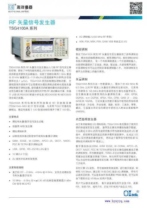
RF 矢量信号发生器TSG4100A系列TSG4100A 系列RF 矢量信号发生器以入门级RF 信号发生器的价格,提供了中档性能和高达200 MHz 的调制带宽。
它们采用新技术提供无杂散输出,实现了低相位噪声(1 GHz 载波在20 kHz 偏置时为-113 dBc/Hz)及超高频率分辨率(在任意频率时为1 μHz)。
TSG4100A 系列标配模拟调制功能。
方便地现场升级软件可以简便地从模拟调制功能转向高级矢量调制和数字调制功能,提供最灵活的配置和最佳的投资保护。
这些仪器完善了泰克其他领先的中档RF 测试解决方案,如基于USB 的RSA306频谱分析仪及MDO4000B 和MDO3000混合域示波器。
TSG4100A 系列仪器采用恒温箱式SC 切割振荡器(TSG410xA-M00或E1型号)时基,与采用TCXO 时基的仪器相比,稳定性提高了100倍(密闭相位噪声下降了100倍)。
主要特点模拟和矢量/数字信号发生功能双基带ARB发生器模拟调制标准以极低成本通过软密钥升级到矢量/数字调制GSM、EDGE、W-CDMA、APCO-25、DECT、NADC、PDC 和TETRA数字调制应用USB、GPIB、RS-232和LAN接口12磅(5.6千克)2U 高和半标准机架宽度主要性能指标真正的DC ~ 2 GHz、4 GHz 或6 GHz ,支持生成模拟信号和矢量/数字信号10 MHz ~ 6 GHz 时≤±0.30 dB 的典型幅度精度(0 dBm CW 信号 @ 22 ºC)I/Q 调制输入(400 MHz RF带宽)ASK, FSK, MSK, PSK, QAM, VSB 和自定义I/Q模拟调制泰克TSG4100A 系列RF 矢量信号发生器提供了多种调制功能。
模式包括幅度调制(AM)、频率调制(FM)、相位调制(ΦM)和脉冲调制模式。
有一个内部调制源及一个外部调制输入。
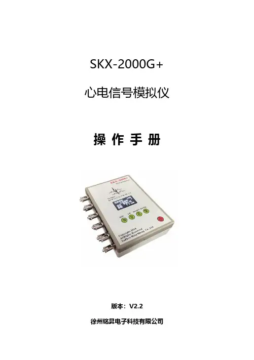
SKX-2000G+心电信号模拟仪操作手册版本:V2.2徐州铭昇电子科技有限公司目录第一章仪器特点注意事项 (3)功能特点 (3)模拟仪的待机工作时间 (3)注意事项 (4)第二章仪器连接说明 (5)第三章软件界面说明 (6)第四章按键说明 (7)第五章模拟仪波形类型及参数介绍 (10)第六章波形详细介绍及检测内容 (13)第七章售后服务 (25)第一章仪器特点注意事项SKX-2000G+心电信号模拟仪是徐州铭昇公司专业开发的一款用于心电类产品开发及检测的信号模拟工具,由于其可以产生多种人体心电级的信号,是开发心电类产品的必备首选工具,其具有宽广的信号幅度范围,可以模拟出多种幅度、频率的心电类信号,是开发心电类产品的重要工具。
本模拟仪同时具有心电类产品的检测功能,用于检测心电类产品的各项参数指标是否可以到达国家标准要求,后续章节将详细介绍检测过程中的各种信号的设置等。
功能特点:1、采用10个万用心电接头,可以方便快捷连接监护仪、心电图机等心电类产品导联线;2、12导联同步心电信号输出,输出不同的12导心电波形;3、内置18650大容量锂电池,电源管理模块,在使用过程中保证电源稳定、低干扰的输出。
选配标准的micro usb通用接口电源充电器;4、采用菜单式操作,参数更改简单、方便、快捷,方便用户设置;5、采用OLED显示屏,显示菜单内容;6、简单的按键操作,菜单管理,使用简单方便;7、内置中英文的波形设置说明,轻松了解波形设置及参数选择。
模拟仪的待机工作时间:1、当电量显示为0%的时候,开机状态下模拟仪可以再工作1分钟后自动关机,如果选择任意按键,则定时关机进行延时,直至1分钟内无按键处理后自动关机;2、当电量显示为10%的时候,开机状态下模拟仪可以再工作5分钟后自动关机,如果选择任意按键,则定时关机进行延时,直至5分钟内无按键处理后自动关机;3、当电量低于0%时模拟仪,将不能再次开机;注意事项:1、SKX-2000G+心电信号模拟仪可以对心电类设备进行定标,定标导联仅限于II,即RA-LL端输出的信号幅度,连接心电设备的RA 导联至模拟仪的RA端,LL导联至模拟仪的LL端,则心电设备采集的信号满足软件中设置的信号幅度范围0.1mV-4mV;2、心电波形中的波形幅度是0.5mV,1mV,2mV,3种固定幅度可选择更改;3、如果定标其他导联时,请按照下列方法进行定标:1)I导联定标:请将导联线RA连接至模拟仪RA端,导联线LA 连接至模拟仪LL端,此时心电设备采集的信号就是I导联的定标信号;2)C导联定标:请将RA、LA、LL并联后连接至模拟仪RA端,C1或者其他胸导联连接至模拟仪LL端,此时采集到的C1(或者其他胸导联)则为标准的定标信号;4、关于偏置电压的检测方法,当测试正向偏置时,请选择正弦波形,并连接心电设备的RA至模拟仪的LL端,心电设备的LL至模拟仪的RA端进行正偏置电压测试;当测试负偏置电压时,请选择正弦波形,并连接心电设备的RA至模拟仪的RA端,心电设备的LL至模拟仪的LL端进行负偏置电压测试;5、当连续一分钟内没有按键操作时,屏幕将会自动关闭,按任一按键后屏幕恢复显示,在屏幕关闭后,指示灯开始工作,每5秒闪烁一次;屏幕恢复显示后,指示灯停止闪烁。
N9020A MXAX-Series Signal Analyzer10 Hz to 3.6, 8.4, 13.6, or 26.5 GHz Data SheetThis data sheet is a summary of the specifications and conditions for MXA signal analyzers. For the complete specifications guide, visit: /find/mxa_specificationsTable of ContentsAccelerate to marketEvery device demands decisionsthat require tradeoffs in your goals—customer specs, through-put, yield. With a highly flexible signal analyzer, you can manage and minimize those tradeoffs. Agilent’s mid-performance MXA is the ultimate accelerator as your products move from design to the marketplace. It has the flexibility to quickly adapt to your evolving test requirements—today and tomorrow. Maximize your flexibil-ity, and accelerate to market, with the Agilent MXA signal analyzer.Definitions and Conditions ...................................................3Frequency and Time Specifications ............................................4Amplitude Accuracy and Range Specifications ...................................6Dynamic Range Specifications ................................................8PowerSuite Measurement Specifications ......................................12General Specifications ......................................................13Inputs and Outputs ........................................................14IQ Analyzer ...............................................................16IQ Analyzer - Option B40 ....................................................17IQ Analyzer - Option B85/B1A/B1X ...........................................18Real-Time Spectrum Analyzer (RTSA). . . . . . . . . . . . . . . . . . . . . . . . . . . . . . . . . . . . . . . . . . 19Related Literature (20)Definitions and ConditionsSpecifications describe the performance of parameters covered by the product warranty and apply to the full temperature range of 0 to 55 °C 1, unless otherwise noted.95th percentile values indicate the breadth of the population (approx. 2 σ) of performance tolerances expected to be met in 95 percent of the cases with a 95 percent confidence, for any ambient temperature in the range of 20 to 30 °C. In addition to the statistical observations of a sample of instruments, these values include the effects of the uncertainties of external calibration references. These values are not warranted. These values are updated occasionally if a significant change in the statistically observed behavior of production instruments is observed.Typical describes additional product performance information that is not covered by the product warranty. It is performance beyond specifications that 80 percent of the units exhibit with a 95 percent confidence level over the temperature range 20 to 30 °C. Typical performance does not include measurement uncer-tainty.Nominal values indicate expected performance, or describe product performance that is useful in the application of the product, but are not covered by the prod-uct warranty.The analyzer will meet its specifications when:• It is within its calibration cycle• Under auto couple control, except when Auto Sweep Time Rules = Accy • Signal frequencies < 10 MHz, with DC coupling applied• The analyzer has been stored at an ambient temperature within the allowed operating range for at least two hours before being turned on; if it had previ-ously been stored at a temperature range inside the allowed storage range, but outside the allowed operating range• The analyzer has been turned on at least 30 minutes with Auto Align set to normal, or, if Auto Align is set to off or partial, alignments must have been run recently enough to prevent an Alert message; if the Alert condition is changed from Time and Temperature to one of the disabled duration choices, the analyzer may fail to meet specifications without informing the userFor the complete specifications guide, visit:/find/mxa_specifications1. For earlier instruments (Serial number prefix < MY/SG/US5051), the full temperature ranges from5 to 50 °C.Frequency and Time Specifications1. Horizontal resolution is span/(sweep points – 1).1. Analysis bandwidth is the instantaneous bandwidth available around a center frequency over which the input signal can be digitized for further analysis orprocessing in the time, frequency, or modulation domain.2. Sweep points = 101. Apply for instruments with S/N prefix ≥ MY/SG/US4910 or earlier instruments with Option PC2 or PC4. Otherwise, refer to theMXA specification guide.Amplitude Accuracy and Range Specifications1. DC coupling required to meet specifications below 50 MHz. With AC coupling, specifications apply at frequencies of 50 MHz and higher. Statistical observa-tions at 10 MHz with AC coupling show that most instruments meet the DC-coupled specifications, however, a small percentage of instruments are expected to have errors exceeding 0.5 dB at 10 MHz at the temperature extreme. The effect at 20 to 50 MHz is negligible but not warranted.2. Apply for instruments with S/N prefix ≥ MY/SG/US5051. For older instruments, refer to the MXA Specification Guide.Dynamic Range Specifications1. N is the LO multiplication factor.Figure 1. Nominal dynamic range – Band 0, for second and third order distortion, 20 Hz to 3.6 GHzFigure 2. Nominal dynamic range – Bands 1 to 4, for second and third order distortion, 3.6 GHz to 26.5 GHz1. Applies for instruments with serial number prefix ≥ MY/SG/US5233. Those instruments ship standard with N9020A-EP2 as the identifier. For nominal valuesat other center frequencies, refer to Figure 3. For earlier instruments, refer to the MXA specifications guide.Figure 3. Nominal phase noise at different center frequencies (Applies for instruments with SN prefix ≥ MY/SG/US5233; ships standard with N9020A-EP2)PowerSuite Measurement SpecificationsGeneral SpecificationsInputs and Outputs1. For additional specifications, please refer to the MXA Signal Analyzer Option BBA: Analog Baseband IQ Inputs Technical Overview,literature number 5989-6538EN.2. For more details, please refer to the Agilent Probe Configuration Guides, literature numbers 5968-7141EN and 5989-6162EN; probe heads are necessary toattach to your device properly and probe connectivity kits such as E2668B, E2669A. or E2675A are required.1. Option MPB installed and enabled.I/Q Analyzer1. Option MPB is installed and enabled.I/Q Analyzer (continued)Option B40 (40 MHz analysis bandwidth, Option B40 is automatically included in Option B85, B1A or B1X)1. Option MPB is installed and enabled.I/Q Analyzer (continued)Option B85/B1A/B1X (85/125/160 MHz analysis bandwidth)1. Option MPB is installed and enabled.1. For additional RTSA specifications, please refer to Option RT1/RT2 Chapter in the MXA Signal Analyzer specification guide (part number: N9020-90113)2. StM = “Signal-to-Mask”Real-Time Spectrum Analyzer (RTSA) 1Option RT1 or RT2Related LiteratureAgilent MXA signal analyzers Brochure5989-5047ENConfiguration Guide 5989-4943EN For more information or literature resources please visit the web:/find/mxacdma2000® is a registered certification mark of the Telecommunications Industry Association. Used under license./quality/find/AdvantageServices Accurate measurements throughout the life of your instruments.Agilent Advantage ServicesThree-Year Warranty/find/ThreeYearWarranty Agilent’s combination of product reliability and three-year warranty coverage is another way we help you achieve your business goals: increased confidence in uptime, reduced cost of ownership and greater convenience.For more information on AgilentTechnologies’ products, applications or services, please contact your local Agilent office. The complete list is available at:/find/contactus Americas Canada (877) 894 4414 Brazil (11) 4197 3600Mexico 01800 5064 800 United States (800) 829 4444 Asia Pacific Australia 1 800 629 485China 800 810 0189Hong Kong 800 938 693India 1 800 112 929Japan 0120 (421) 345Korea 080 769 0800Malaysia 1 800 888 848Singapore 180****8100Taiwan 0800 047 866Other AP Countries (65) 375 8100 Europe & Middle East Belgium 32 (0) 2 404 93 40 Denmark 45 45 80 12 15Finland 358 (0) 10 855 2100France 0825 010 700**0.125 €/minuteGermany 49 (0) 7031 464 6333 Ireland 1890 924 204Israel 972-3-9288-504/544Italy 39 02 92 60 8484Netherlands 31 (0) 20 547 2111Spain 34 (91) 631 3300Sweden 0200-88 22 55United Kingdom 44 (0) 118 927 6201For other unlisted countries: /find/contactusRevised: January 6, 2012Product specifications and descriptions in this document subject to change without notice.© Agilent Technologies, Inc. 2013Published in USA, July 31, 20135989-4942EN/find/mxaLAN eXtensions for Instruments puts the power of Ethernet and the Web inside your test systems. Agilent is a founding member of the LXI consortium.Agilent Channel Partnersw w w /find/channelpartners Get the best of both worlds: Agilent’s measurement expertise and product breadth, combined with channel partner convenience./find/myagilentA personalized view into the information most relevant to you.myAgilentmy Agilent。
tfg2000信号发生器使用说明TFG 2000系列DDS 函数信号发生器简介本书的内容涵盖下述的TFG 2000 DDS 函数信号发生器:TFG2003、TFG2006、TFG2006V、TFG2015、TFG2015V、TFG2030、TFG2030V、TFG2050、TFG2050V、TFG2300、TFG2300VTFG2000系列DDS函数信号发生器采用直接数字合成技术(DDS), 具有快速完成测量工作所需的高性能指标和众多的功能特性。
其简单而功能明晰的前面板及液晶汉字或荧光字符显示功能使您更便于操作和观察,选装的扩展功能模块,可使您获得增强的系统功能。
下面的介绍体现了该系列信号发生器优异的技术指标和强大功能特性的完美结合。
? 频率精度高: 频率精度可达到10-5 数量级? 频率分辩率高: 全范围频率分辨率40mHz? 无量程限制: 全范围频率不分档,直接数字设置? 无过渡过程: 频率切换时瞬间达到稳定值,信号相位和幅度连续无畸变? 波形精度高: 输出波形由函数计算值合成,波形精度高,失真小? 存储特性: 可以存储40组不同频率和幅度的信号,在需要时可随时重现? 猝发特性: 可以对信号进行门控输出和猝发计数输出? 扫描特性:具有频率扫描和幅度扫描功能,扫描起止点任意设置? 调制特性:可以输出多种调制信号AM,FM,FSK,ASK,PSK ? 计算功能: 可以选用频率或周期,幅度有效值或峰峰值? 操作方式: 全部按键操作,两级菜单显示,直接数字设置或旋钮连续调节? 高可靠性: 大规模集成电路,表面贴装工艺,可靠性高,使用寿命长? 程控特性: 可以选配GPIB接口或RS232接口,组成自动测试系统? 频率测量:可以选配频率计数器,对外部信号进行频率测量或周期测量? 功率放大:可以选配功率放大器,输出功率可以达到8WTFG2000系列DDS函数信号发生器使用指南石家庄市无线电四厂石家庄数英电子科技有限公司1TFG2000系列DDS函数信号发生器及附件(代装箱单)? TFG2×××DDS函数信号发生器1台? 2米三芯电源线1条? 1.5米信号输出线2条? 《用户使用指南》1本TFG2000系列DDS函数信号发生器选件? GPIB(IEEE-488)测量仪器标准接口? RS232串行接口? 频率计? 功率放大器? 温补晶振:稳定度±(5×10)/日-7TFG2000系列DDS函数信号发生器使用指南石家庄市无线电四厂石家庄数英电子科技有限公司2本书概要快速入门:第一章帮助您快速掌握信号发生器的基本使用方法。
SDS2000X 数字示波器快速指南SDS2000X 快速指南-I深圳市鼎阳科技有限公司版权所有。
本公司产品受已获准及尚在审批的中华人民共和国专利的保护。
本公司保留改变规格及价格的权利。
本手册提供的信息取代以往出版的所有资料。
未经本公司同意,不得以任何形式或手段复制、摘抄、翻译本手册的内容。
注:SIGLENT 是深圳市鼎阳科技有限公司的注册商标。
了解下列安全性预防措施,以避免人身伤害,并防止本产品或与其相连接的任何其它产品受到损坏。
为了避免可能发生的危险,请务必按照规定使用本产品。
使用适当的电源线--只允许使用所在国家认可的本产品专用电源线。
将产品接地--本产品通过电源电缆的保护接地线接地。
为了防止电击,在连接本产品的任何输入或输出端之前,请务必将本产品正确接地。
正确连接信号线--信号线与地电势相同,请勿将地线连至高电压。
查看所有终端额定值--为了避免火灾或电击,请查看本产品的所有额定值和标记说明。
请在连接产品前阅读产品手册,以便了解有关额定值的详细信息。
使用合适的过压保护--确保没有过电压(如由雷电造成的电压)到达该产品,否则可能导致操作人员遭受电击。
防静电保护--静电会造成仪器损坏,应尽可能在防静电区进行测试。
连接电缆到仪器前,应将其内外导体短暂接地以释放静电。
保持良好的通风 --通风不当会引起仪器温度升高,进而引起仪器损坏。
使用时应保持良好的通风,定期检查通风口和风扇。
避免电路外露 --电源接通后,请勿接触外露的接头和元件。
请勿开盖操作--请勿在仪器机箱打开时运行本产品。
使用合适的保险丝 --只允许使用本产品指定规格的保险丝。
请勿在潮湿或易燃易爆的环境下操作注意搬运安全 --为避免仪器在搬运时滑落,造成仪器面板上的按键、旋钮或接口等部件损坏,请在搬运仪器的过程中注意安全。
怀疑产品出故障时,请勿操作 --如怀疑产品有故障,请联系SIGLENT授权的维修人员进行检测。
任何对于本产品的维护、调整或零件更换必须由SIGLENT授权的维修人员执行。


PicoScope® 2000 SeriesUltra-compact PC oscilloscopes The compact alternative to a benchtop oscilloscope2 or 4 analog channelsMSO models with 16 digital channelsUp to 100 MHz bandwidthUp to 1 GS/s sampling rateUp to 128 MS buffer memoryBuilt-in arbitrary waveform generatorUSB-connected and powered2-channel oscilloscope: 2206B, 2207B and 2208BIntroducing the PicoScope 2000 SeriesThe PicoScope 2000 Series offers you a choice of 2-channel and 4-channeloscilloscopes, plus mixed-signal oscilloscopes (MSOs) with 2 analog + 16 digitalinputs. All models feature a spectrum analyzer, function generator, arbitrary waveform generator and serial bus analyzer, and the MSO models also include a logic analyzer.The PicoScope 2000A models all deliver unbeatable value for money, with excellent waveform visualization and measurement to 25 MHz for a range of analog and digital electronic and embedded system applications. They are ideal for education, hobby and field service use.The PicoScope 2000B models have the added benefits of deep memory (up to 128 MS), higher bandwidth (up to 100 MHz) and faster waveform update rates, giving you the performance you need to carry out advanced analysis of your waveform, including serial decoding and plotting frequency against time.Advanced oscilloscope displayThe PicoScope 6 software takes advantage of the display size, resolution andprocessing power of your PC – in this case displaying four analog signals, a zoomed view of two of the signals (undergoing serial decoding), and a spectrum view of athird, all at the same time. Unlike a conventional benchtop oscilloscope, the size of the display is limited only by the size of your computer monitor. The software is also easy to use on touch-screen devices – you can pinch to zoom and drag to scroll.4-channel oscilloscope2-channel oscilloscope: 2204A and 2205A2+16-channel mixed-signal oscilloscope (MSO)Powerful, portable and super-smallThe PicoScope 2000 Series oscilloscopes are compact enough to fit easily into your laptop bag along with all their probes and leads. These modern alternatives to bulky benchtop devices are ideal for a wide range of applications including design, test, education, service, monitoring, fault-finding and repair, and are perfect for engineers on the move.Fast samplingThe PicoScope 2000 Series oscilloscopes provide fast real-time sampling rates of up to 1 GS/s on the analog channels. This represents a timing resolution of 1 ns.For repetitive analog signals, equivalent-time sampling (ETS) mode can boost the maximum effective sampling rate up to 10 GS/s, allowing even finer resolution down to 100 ps. All scopes support pre-trigger and post-trigger capture using the full memory depth.High-end features as standardBuying a PicoScope is not like making a purchase from other oscilloscope companies, where increased functionality can considerably raise the price. PicoScopes are all-inclusive instruments, with no need for expensive upgrades to unlock the hardware. Other advanced features such as resolution enhancement, mask limit testing, serial decoding, advanced triggering, automatic measurements, math channels (including the ability to plot frequency and duty cycle against time), XY mode and segmented memory are all included in the price.FlexibilityThe PicoScope software offers a breadth of advanced features with a user-friendly interface. As well as the standard Windows installation, PicoScope Beta software also works effectively on Linux and macOS operating systems, giving you the freedom to operate your PicoScope from your chosen platform.Unique commitment to product supportYour PicoScope gets better the longer you use it, thanks to the regular free updates we supply for both the PC software and the oscilloscope firmware throughout the life of the product. The performance and functionality of the scope both keep improving, without you paying a penny more than the purchase price.This level of support, combined with the personal service provided by our technical and sales support teams, is reflected in consistently excellent customer feedback.High signal integrityAt Pico Technology we’re proud of the dynamic performance of our products. Careful front-end design and shielding reduce noise, crosstalk and harmonic distortion. Decades of oscilloscope design experience can be seen in improved pulse response and bandwidth flatness.The result is simple: when you probe a circuit, you can trust in the waveform you see on the B connectivityThe USB connection makes printing, copying, saving, and emailingyour data from the field quick and easy. The high-speed USBinterface allows fast data transfer, while USB powering removesthe need to carry around a bulky external power supply.Deep capture memoryPicoScope 2000 Series ‘B’ models have waveform capture buffers ranging from 32 to 128 megasamples – many times larger than competing scopes. Deep memory enables the capture of long-duration waveforms at maximum sampling speed. In fact, some PicoScope 2000 Series models can capture 100 ms waveforms with 1 ns resolution. In contrast, the same 100 ms waveform captured by an oscilloscope with a 10 megasample memory would have just 10 ns resolution.Deep memory can be useful in other ways too: PicoScope 6 lets you divide the capture memory into a number of segments, up to a maximum of 10 000. You can set up a trigger condition to store a separate capture in each segment, with as little as 1 µs dead time between captures. Once you have acquired the data, you can step through the memory one segment at a time until you find the event you are looking for.Powerful tools are included to allow you to manage and examine all of this data. As well as functions such as mask limit testing and color persistence mode, the PicoScope 6 software enables you to zoom into your waveform by a factor of several million. The Zoom Overview window allows you to easily control the size and location of the zoom area. Other tools, such as the waveform buffer, serial decoding and hardware acceleration work with the deep memory, making the PicoScope 2000 Series some of the best-value oscilloscopes on the market.PicoScope 6 softwareThe PicoScope software display can be as basic or as detailed as you need. Begin with a single view of one channel, and then expand the display to include up to four live channels (model-dependent), plus math channels and reference waveforms. Display multiple scope and spectrum views with automatic or custom layouts and quickly access all the most frequently-used controls from the toolbars, leaving the display clear for your waveforms.Oscilloscope controls: PicoScope’s full analog-domain controls, including zoom, filtering, andfunction generatovr, are all available in MSO digital signal mode.Mixed digital and analog signalsThe PicoScope 2000 MSO models add 16 digital channels to their two analog channels, enabling you to accurately time-correlate analog and digital channels. You can group digital channels together and display them as a bus, with each bus value displayed in hex, binary or decimal, or as a level (for DAC testing). You can set advanced triggers across both the analog and digital channels.The digital inputs also bring extra power to the serial decoding options. You can decode serial data on all analog and digital channels simultaneously, giving you up to 20 channels of data – for example decoding multiple SPI, I²C, CAN bus, LIN bus and FlexRay signals all at the same time.Persistence modePicoScope 6 persistence mode options allow you to see old and new data superimposed, with newer waveforms drawn in a brighter color or deeper shade. This makes it easy to spot glitches and dropouts and estimate their relative frequency – useful for displaying and interpreting complex analog signals such as video waveforms and analog modulation signals.The PicoScope 2000 Series’ hardware acceleration means that, in Fast Persistence mode, waveform update rates of up to 80 000 waveforms per second are achievable. Color-coding or intensity-grading shows which areas are stable and which are intermittent. Choose between analog intensity, digital color and fast display modes or create your own custom setup.Spectrum analyzerThe spectrum view plots amplitude against frequency and is ideal for finding noise, crosstalk or distortion in signals. PicoScope 6 uses a fast Fourier transform (FFT) spectrum analyzer, which (unlike a traditional swept spectrum analyzer) can display the spectrum of a single, non-repeating waveform.With a click of a button, you can display a spectrum plot of the active channels, with a maximum frequency of up to 200 MHz. A comprehensive range of settings gives you control over the number of spectrum bins, window functions, scaling (including log/log) and display mode (instantaneous, average or peak-hold).Display multiple spectrum views with different channel selections and zoom factors, and place these alongside time-domain views of the same data. Choose froma number of automatic frequency-domain measurements to add to the display, including THD, THD+N, SNR, SINAD and IMD. You can apply mask limit testing to a spectrum and can even use the AWG and spectrum mode together to perform sweptscalar network analysis.Serial decoding and analysisThe PicoScope 2000 Series oscilloscopes include serial decoding capability as standard. The PicoScope 6 software has support for 20 protocols including I2C, SPI, CAN, RS-232, Manchester and DALI. Decoding helps you see what is happening in your design to identify programming and timing errors and check for other signal integrity issues. Timing analysis tools help to show the performance of each design element, identifying parts of the design that need to be improved to optimize overall system performance.You can capture and decode several protocols at a time, in any combination, the only limit being the number of available channels – 18 for MSO models, as you can decode serial data on all analog and digital inputs simultaneously. The ability to observe data flow across a bridge (such as CAN bus in, LIN bus out) is incredibly powerful. The deep memory of the PicoScope 2000B models makes them ideal for serial decoding, as they can handle many thousands of frames of data.GRAPH FORMAT shows the decoded data (in hex, binary, decimal or ASCII) in a timing diagram format, beneath the waveform on a common time axis, with error frames marked in red. You can zoom in on these frames toinvestigate noise or distortion, and eachpacket field is assigned a different color,so the data is easy to read.TABLE FORMAT shows a list of thedecoded frames, including the data andall flags and identifiers. You can set upfiltering conditions to display only theframes you are interested in or search forframes with specified properties.The statistics option reveals more detailabout the physical layer such as frametimes and voltage levels. PicoScope 6 canalso import a spreadsheet to decode thedata into user-defined text strings.Waveform buffer and navigatorEver spotted a glitch on a waveform, but by the time you’ve stopped the scope it’s gone? With PicoScope you no longer need to worry about missing glitches or other transient events, as it can store the last 10 000 waveforms in its circular waveform buffer.The buffer navigator provides an efficient way of navigating and searching through waveforms, effectively letting you turn back time. When carrying out a mask limit test, you can also set the navigator to show only mask fails, enabling you to find any glitches quickly.Mask limit testingMask limit testing allows you to compare live signals against known good signals, and is designed for production and debugging environments. Simply capture a known good signal, generate a mask around it and then use the alarms to automatically save any waveform (complete with a time stamp) that violates the mask. PicoScope 6 will capture any intermittent glitches and show a failure count in the Measurements window (which you can still use for other measurements). You can also set the waveform buffer navigator to show only mask fails, enabling you to find any glitches quickly.Mask files are easy to edit (numerically or graphically), import and export, and you can simultaneously run mask limit tests on multiple channels and in multiple viewports.AlarmsYou can program PicoScope 6 to execute actions when certain events occur.The events that can trigger an alarm include mask limit fails, trigger events and buffers full.PicoScope 6 actions include saving a file, playing a sound, executing a program and triggering the arbitrary waveform generator.Automatic measurementsPicoScope allows you to automatically display a table of calculated measurements for troubleshooting and analysis. Using the built-in measurement statistics you can see the average, standard deviation, maximum and minimum of each measurement as well as the live value.You can add as many measurements as you need on each view – 18 differentmeasurements are available in scope mode and 11 in spectrum mode. For information on these measurements, see Automatic Measurements in the Specificationstable.Scope modeSpectrum modeArbitrary waveform and function generatorAll PicoScope 2000 Series oscilloscopes have a built-in function generator and arbitrary waveform generator (AWG). The function generator can produce sine, square, triangle and DC level waveforms, and many more besides, while the AWG allows you to import waveforms from data files or create and modify them using the built-in graphical AWG editor.As well as level, offset and frequency controls, advanced options allow you to sweep over a range of frequencies. Combined with the advanced spectrum mode, with options including peak hold, averaging and linear/log axes, this creates a powerful tool fortesting amplifier and filter responses.Advanced triggersThe PicoScope 2000 Series offers an industry-leading set of advanced triggers including pulse width, windowed and dropout.The digital trigger available on MSO models allows you to trigger the scope when any or all of the 16 digital inputs match a user-defined pattern. You can specify a condition for each channel individually, or set up a pattern for all channels at once using a hexadecimal or binary value.You can also use the logic trigger to combine the digital trigger with an edge or window trigger on any of the analog inputs, for example to trigger on data values in a clocked parallel bus.Digital triggering architectureIn 1991, Pico Technology pioneered the use of digital triggering and precision hysteresis using theactual digitized data. Traditionally, digital oscilloscopes have used an analog trigger architecture based on comparators, which can cause time and amplitude errors that cannot always be calibrated out. Additionally, the use of comparators can often limit the trigger sensitivity at high bandwidths and can create a long trigger rearm delay.Pico’s technique of fully digital triggering reduces trigger errors and allows our oscilloscopes to trigger on the smallest signals, even at the full bandwidth, so you can set trigger levels and hysteresis with high precision and resolution.The digital trigger architecture also reduces the rearm delay. Combined with the segmented memory, thisenables you to use rapid triggering to capture 10 000 waveforms in 10 ms in 8-bit mode.Custom probesThe custom probes feature allows you to correct for gain, attenuation, offsets and nonlinearities in probes, transducers and other sensors, and to measure quantities other than voltages (such as current, power or temperature).Definitions for standard Pico-supplied probes are built in, but you can also create your own using linear scaling or even an interpolated data table, and save them for later use.Math channels and filtersWith PicoScope 6 you can perform a variety of mathematical calculations on your inputsignals and reference waveforms. Select simple functions such as addition and inversion,or open the equation editor to create complex functions involving filters (lowpass,highpass, bandpass and bandstop filters), trigonometry, exponentials, logarithms,statistics, integrals and derivatives.Display up to eight real or calculated channels in each scope view. If you run out ofspace, just open another scope view and add more. You can also use math channels toreveal new details in complex signals, for example graphing the changing duty cycle orfrequency of your signal over time.Plot frequency against time with PicoScope 6All oscilloscopes can measure the frequency of awaveform, but often you need to know how thatfrequency changes over time, which is a difficultmeasurement to make. The freq math function cando exactly this: in this example, the top waveform’sfrequency is being modulated by a ramp function, asplotted in the bottom waveform.A separate math function allows you to plot duty cyclein a similar way.PicoLog ® 6 supportAll PicoScope 2000 Series oscilloscopes are now supported in PicoLog 6, allowing you to view and record signals on multiple units in one capture.PicoLog 6 allows sample rates of up to 1 kS/s per channel, and is ideal for long-term observation of general parameters, such as voltage or current levels, on several channels at the same time. It is less suitable for waveshape or harmonic analysis: use the PicoScope 6 software for these tasks.You can also use PicoLog 6 to view data from your oscilloscope alongside a data logger or other device. For example, you could measure voltage and current with your PicoScope and plot both against temperature using a , or humidity with a DrDAQ multipurpose data logger .PicoLog 6 is available for Windows, macOS and Linux, including Raspbian.PicoSDK ® – write your own appsOur software development kit, PicoSDK, allows you to write your own software and includes drivers for Windows, macOS and Linux. Example code supplied on our GitHub organization page shows how to interface to third-party software packages such as National Instruments LabVIEW and MathWorks MATLAB.Amongst other features, the drivers support data streaming, a mode that captures continuous gap-free data directly to your PC at rates of up to 125 MS/s, so you are not limited by the size of your scope’s capture memory. Sampling rates in streaming mode are subject to PC specifications and application loading.There is also an active community of PicoScope 6 users who share both code and whole applications on our Test and Measurement Forum and the PicoApps section of the website. The Frequency Response Analyzer shown here is one of the most popular of theseapplications.20-way 25 cm digital MSO cableMSO test clipsKit contents and accessoriesThe PicoScope 2000 Series oscilloscope kit contains the following items:• USB 2.0 (USB 3.0/3.1 compatible) cable• Two or four x1/x10 passive probes (except kits specified as without probes)• Digital input cable (MSO models only)• 20 logic test clips (MSO models only)•Quick Start GuideProbes, cables and clipsYour PicoScope 2000 Series oscilloscope kit comes with probes trimmed to match the performance of your oscilloscope.MSO models are also supplied with an MSO cable and 20 test clips.Oscilloscope probeQuick product selector Array 2-channel oscilloscopes4-channel oscilloscopesMixed-signal oscilloscopes2 analog + 16 digital inputsUsers writing their own apps can find example programs for all platforms on the Pico Technology organization page on .Ordering informationPP906PicoScope 2204A10 MHz 2-channel oscilloscopePP966PicoScope 2205A-D225 MHz 2-channel oscilloscope without probesPP907PicoScope 2205A25 MHz 2-channel oscilloscopePQ012PicoScope 2206B50 MHz 2-channel oscilloscopePQ013PicoScope 2207B70 MHz 2-channel oscilloscopePQ014PicoScope 2208B100 MHz 2-channel oscilloscopePQ015PicoScope 2405A25 MHz 4-channel oscilloscopePQ016PicoScope 2406B50 MHz 4-channel oscilloscopePQ017PicoScope 2407B70 MHz 4-channel oscilloscopePQ018PicoScope 2408B100 MHz 4-channel oscilloscopePQ008PicoScope 2205A MSO25 MHz 2+16 channel mixed-signal oscilloscopePQ009PicoScope 2206B MSO50 MHz 2+16 channel mixed-signal oscilloscopePQ010PicoScope 2207B MSO70 MHz 2+16 channel mixed-signal oscilloscopePQ011PicoScope 2208B MSO100 MHz 2+16 channel mixed-signal oscilloscopeReplacement accessoriesTA136TA136 logic cable20-way 25 cm digital cable (suitable for MSOs only)TA139TA139 test clips Pack of 10 logic test clips (suitable for MSOs only)Calibration service* Prices are correct at the time of publication. Sales taxes not included. Please contact Pico Technology for the latest prices before ordering.Errors and omissions excepted. Pico Technology , PicoScope, PicoSDK and FlexRes are internationally registered trademarks of Pico Technology Ltd. LabVIEW is a trademark of National Instruments Corporation. Linux is the registered trademark of Linus Torvalds, registered in the U.S. and other countries. macOS is a trademark of Apple Inc., registered in the U.S. and other countries. MATLAB is a registered trademark of The MathWorks, Inc. Windows and Excel are registered trademarks of Microsoft Corporation in the United States and other countries. MM071.en-5. Copyright © 2016–2019 Pico Technology Ltd. All rights reserved.More products in the Pico Technology range...PicoScope 4000 SeriesA varied range of high-resolutionoscilloscopes for a multitude of analog applications.Models available with 2 or 4 channels plus optional IEPE interface, 2 channels at 16-bit resolution, 4 true differential channel inputs for extra-low-voltage or mains CAT III applications, or 8 channelsat 12-bit resolution.PicoScope 3000 SeriesVersatile general-purpose 2- and 4-channel oscilloscopes and MSOs, suitable for a huge range of analog and digital applications.All models have a maximum sampling rate of 1 GS/s, USB 3.0 connectivity and access to the DeepMeasure™ tool.Up to 200 MHz bandwidth and 512 MScapture memory.TC-088-channel temperature data logger. Accepts all popular thermocouples to record temperatures from −270 °C to +1820 °CUp to 10 measurements per second at 20-bit resolution. Optional terminal boardfor voltage and current measurement.DrDAQBuilt-in sensors for light, sound and temperature, plus pH and redox input, scope input (max. sampling rate 1 MS/s), 3 sensor sockets, 4 digital I/O connections and a function generator.This flexible data logger runs on PicoLog 6 and PicoScope 6 software and is ideal forhobby or educational applications.UK global headquarters:Pico Technology James HouseColmworth Business Park St. NeotsCambridgeshire PE19 8YPUnited Kingdom☎ +44 (0) 1480 396 395✉******************North America regional office:Pico Technology320 N Glenwood Blvd TylerTexas 75702United States☎ +1 800 591 2796✉******************Asia-Pacific regional office:Pico TechnologyRoom 2252, 22/F, Centro 568 Hengfeng Road Zhabei District Shanghai 200070PR China☎ +86 21 2226-5152✉***********************。
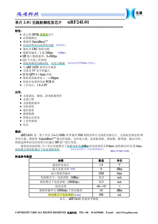
单片2.4G 无线射频收发芯片nRF24L01===================================================特性● 真正的GFSK● 内置链路层● 增强型ShockBurst TM● 自动应答及自动重发功能 ● 地址及CRC 检验功能● 数据传输率1或2Mbps ● SPI 接口数据速率0~8Mbps ● 125个可选工作频道● 很短的频道切换时间可用于跳频 ● 与nRF 24XX 系列完全兼容 ● 可接受5V 电平的输入 ● 20脚QFN 44mm 封装 ● 极低的晶振要求60ppm ● 低成本电感和双面PCB 板 ● 工作电压 1.9~3.6V 应用● 无线鼠标键盘游戏机操纵杆 ● 无线门禁● 无线数据通讯 ● 安防系统 ● 遥控装置 ● 遥感勘测● 智能运动设备 ● 工业传感器 ● 玩具 概述:nRF24L01是一款工作在2.4~2.5GHz 世界通用ISM 频段的单片无线收发器芯片无线收发器包括:频率发生器增强型SchockBurst TM 模式控制器功率放大器晶体振荡器调制器解调器输出功率频道选择和协议的设置可以通过SPI 接口进行设置极低的电流消耗当工作在发射模式下发射功率为-6dBm 时电流消耗为9.0mA 接收模式时为12.3mA掉电模式和待机模式下电流消耗更低 快速参考数据参数 数值 单位最低供电电压 1.9 V最大发射功率 0 dBm最大数据传输率 2000 kbps发射模式下电流消耗0dBm 11.3 mA接收模式下电流消耗2000kbps 12.3 mA温度范围 -40~ +85数据传输率为1000kbps 下的灵敏度 -85 dBm掉电模式下电流消耗 900 nA 表1 nRF24L01快速参考数据很短的时间???hehe,,有想法,,,是Mbps,,,,要利用好,,,这是在此功耗下,,,大的功耗消耗更大丠丠dBm=10*lg(P/1mW)为0.9uA 1mW W分类信息型号描述版本nRF24L01 IC 裸片 DnRF24L01 20脚QFN 4*4mm,RoHS&SS-00259compliant DnRF24L01-EVKIT 评估套件 1.0表2nRF24L01 分类信息结构方框图:图1 nRF24L01 及外部接口引脚及其功能引脚名称引脚功能描述1 CE 数字输入 RX或TX模式选择2 CSN 数字输入 SPI片选信号3 SCK 数字输入 SPI时钟4 MOSI 数字输入从SPI数据输入脚5 MISO 数字输出从SPI数据输出脚6 IRQ 数字输出可屏蔽中断脚7 VDD 电源电源+3V8 VSS 电源接地0V9 XC2 模拟输出晶体震荡器2脚10 XC1 模拟输入晶体震荡器1脚/外部时钟输入脚11 VDD_PA 电源输出给RF的功率放大器提供的+1.8V电源12 ANT1 天线天线接口113 ANT2 天线天线接口214 VSS 电源接地0V15 VDD 电源电源+3V16 IREF 模拟输入参考电流17 VSS 电源接地0V18 VDD 电源电源+3V19 DVDD 电源输出去耦电路电源正极端20 VSS 电源接地0V表3nRF24L01引脚功能图2 引脚封装电气特性参数+27 +85 高电平输出电压=-0.5mA 高电平输出电压=0.5mA 160 320R GFSK >0 1800 2000 单通道工作电流单通道工作电流0.1%BRE(@2000kbps)图3nRF24L01外形封装尺寸极限范围供电电压VDD…………………………….-0.3V~+3.6VVSS (0V)输入电压V I………………………………-0.3V~5.25V输出电压V O……………………………. VSS~VDD总功耗=85……………………… 60mWPD T温度工作温度……………………-40~+85存储器温度…………………-40~+125注意:若超出上述极限值可能对元器件有损害静电敏感元件术语表术语描述ACK 确认信号应答信号ART 自动重发CE 芯片使能CLK 时钟信号CRC 循环冗余校验CSN 片选非ESB 增强型ShockBrust TMGFSK 高斯键控频移IRQ 中断请求ISM 工业科学医学LNA 低噪声放大LSB 最低有效位LSByte 最低有效字节Mbps 兆位/秒MCU 微控制器MISO 主机输入从机输出MOSI 主机输出从机输入MSB 最高有效位MSByte 最高有效字节PCB 印刷电路板PER 数据包误码率PID 数据包识别位PLD 载波PRX 接收源PTX 发射源PWR_DWN 掉电PWR_UP 上电RX 接收RX_DR 接收数据准备就绪SPI 串行可编程接口TX 发送TX_DS 已发送数据表5术语表功能描述工作模式nRF24L01可以设置为以下几种主要的模式模式PWR_UP PRIM_RX CE FIFO寄存器状态-接收模式 1 1 1数据在TX FIFO寄存器中发送模式 1 0 1发送模式 1 0 10 停留在发送模式直至数据发送完TX FIFO为空待机模式II 1 0 1待机模式I 1 - 0无数据传输-掉电模式0 - -表6 nRF24L01主要工作模式关于nRF24L01 I/O脚更详细的描述请参见下面的表7nRF24L01在不同模式下的引脚功能引脚名称 方向 发送模式接收模式 待机模式 掉电模式CE 输入 高电平>10us 高电平低电平-CSN 输入 SPI 片选使能低电平使能SCK 输入 SPI 时钟 MOSI输入 SPI 串行输入 MISO 三态输出 SPI 串行输出 IRQ输出 中断低电平使能表7nRF24L01引脚功能待机模式待机模式I在保证快速启动的同时减少系统平均消耗电流在待机模式I 下晶振正常工作在待机模式II 下部分时钟缓冲器处在工作模式当发送端TX FIFO 寄存器为空并且CE 为高电平时进入待机模式II 在待机模式期间寄存器配置字内容保持不变掉电模式在掉电模式下,nRF24L01各功能关闭保持电流消耗最小进入掉电模式后nRF24L01停止工作但寄存器内容保持不变启动时间见表格13掉电模式由寄存器中PWR_UP 位来控制数据包处理方式nRF24L01有如下几种数据包处理方式ShockBurst TM 与nRF2401nRF24E1nRF2402nRF24E2数据传输率为1Mbps 时相同 增强型ShockBurst TM 模式ShockBurst TM 模式ShockBurst 模式下nRF24L01可以与成本较低的低速MCU 相连高速信号处理是由芯片内部的射频协议处理的nRF24L01提供SPI 接口数据率取决于单片机本身接口速度ShockBurst 模式通过允许与单片机低速通信而无线部分高速通信减小了通信的平均消耗电流在ShockBurst TM 接收模式下当接收到有效的地址和数据时IRQ 通知MCU 随后MCU 可将接收到的数据从RX FIFO 寄存器中读出 在ShockBurst TM发送模式下nRF24L01自动生成前导码及CRC 校验参见表格12数据发送完毕后IRQ 通知MCU 减少了MCU 的查询时间也就意味着减少了MCU 的工作量同时减少了软件的开发时间nRF24L01内部有三个不同的RX FIFO 寄存器6个通道共享此寄存器和三个不同的TX FIFO 寄存器在掉电模式下待机模式下和数据传输的过程中MCU 可以随时访问FIFO 寄存器这就允许SPI 接口可以以低速进行数据传送并且可以应用于MCU 硬件上没有SPI 接口的情况下增强型的ShockBurst TM 模式增强型ShockBurst TM 模式可以使得双向链接协议执行起来更为容易有效典型的双向链接为发送方要求终端设备在接收到数据后有应答信号以便于发送方检测有无数据丢失一旦数据丢失则通过重新发送功能将丢失的数据恢复增强型的ShockBurst TM 模式可以同时控制应答及重发功能而无需增加MCU 工作量确实,,由硬件完成,,减小了量,,,图4 nRF24L01在星形网络中的结构图nRF24L01在接收模式下可以接收6路不同通道的数据见图4每一个数据通道使用不同的地址但是共用相同的频道也就是说6个不同的nRF24L01设置为发送模式后可以与同一个设置为接收模式的nRF24L01进行通讯而设置为接收模式的nRF24L01可以对这6个发射端进行识别数据通道0是唯一的一个可以配置为40位自身地址的数据通道1~5数据通道都为8位自身地址和32位公用地址所有的数据通道都可以设置为增强型ShockBurst 模式nRF24L01在确认收到数据后记录地址并以此地址为目标地址发送应答信号在发送端数据通道0被用做接收应答信号因此数据通道0的接收地址要与发送端地址相等以确保接收到正确的应答信号见图5 选择地址举例图5应答地址确定举例nRF24L01配置为增强型的ShockBurst TM发送模式下时只要MCU 有数据要发送nRF24L01就会启动ShockBurst TM 模式来发送数据在发送完数据后nRF24L01转到接收模式并等待终端的应答信号如果没有收到应答信号nRF24L01将重发相同的数据包直到收到应答信号或重发次数超过SETUP_RETR_ARC 寄存器中设置的值为止如果重发次数超过了设定值则产生MAX_RT 中断只要收到确认信号nRF24L01就认为最后一包数据已经发送成功接收方已经收到数据把TX FIFO 中的数据清除掉并产生TX_DS 中断IRQ 引脚置高在发射器中,,通道0要接收应答回来的信号,,所以应该与发送通道地址,,,相同,,在增强型ShockBurst模式下nRF24L01有如下的特征当工作在应答模式时快速的空中传输及启动时间极大的降低了电流消耗低成本nRF24L01集成了所有高速链路层操作比如重发丢失数据包和产生应答信号无需单片机硬件上一定有SPI口与其相连SPI 接口可以利用单片机通用I/O口进行模拟 由于空中传输时间很短极大的降低了无线传输中的碰撞现象由于链路层完全集成在芯片上非常便于软硬件的开发增强型ShockBurstTM发送模式1配置寄存器位PRIM_RX为低2当MCU有数据要发送时接收节点地址TX_ADDR和有效数据(TX_PLD)通过SPI接口写入nRF24L01发送数据的长度以字节计数从MCU写入TX FIFO当CSN为低时数据被不断的写入发送端发送完数据后将通道0设置为接收模式来接收应答信号其接收地址(RX_ADDR_P0)与接收端地址(TX_ADDR)相同例在图5中数据通道5的发送端(TX5)及接收端(RX)地址设置如下TX5TX_ADDR=0xB3B4B5B605TX5RX_ADDR_P0=0xB3B4B5B605RX RX_ADDR_P5=0xB3B4B5B6053设置CE为高启动发射CE高电平持续时间最小为10 us4nRF24L01 ShockBurst TM模式无线系统上电启动内部16MHz时钟无线发送数据打包见数据包描述高速发送数据由MCU设定为1Mbps或2Mbps5如果启动了自动应答模式自动重发计数器不等于0ENAA_P0=1无线芯片立即进入接收模式如果在有效应答时间范围内收到应答信号则认为数据成功发送到了接收端此时状态寄存器的TX_DS位置高并把数据从TX FIFO中清除掉如果在设定时间范围内没有接收到应答信号则重新发送数据如果自动重发计数器ARC_CNT溢出超过了编程设定的值则状态寄存器的MAX_RT位置高不清除TX FIFO中的数据当MAX_RT或TX_DS为高电平时IRQ引脚产生中断IRQ中断通过写状态寄存器来复位见中断章节如果重发次数在达到设定的最大重发次数时还没有收到应答信号的话在MAX_RX中断清除之前不会重发数据包数据包丢失计数器(PLOS_CNT)在每次产生MAX_RT中断后加一也就是说重发计数器ARC_CNT计算重发数据包次数PLOS_CNT计算在达到最大允许重发次数时仍没有发送成功的数据包个数6如果CE置低则系统进入待机模式I如果不设置CE为低则系统会发送TX FIFO寄存器中下一包数据如果TX FIFO寄存器为空并且CE为高则系统进入待机模式II.7如果系统在待机模式II当CE置低后系统立即进入待机模式I.增强型ShockBurst TM接收模式1 ShockBurst TM接收模式是通过设置寄存器中PRIM_RX位为高来选择的准备接收数据的通道必须被使能EN_RXADDR寄存器所有工作在增强型ShockBurst TM模式下的数据通道的自动应答功能是由(EN_AA寄存器)来使能的有效数据宽度是由RX_PW_Px寄存器来设置的地址的建立过程见增强型ShockBurst TM发送章节23 130us后4接收到有效的数据包后地址匹配CRC检验正确数据存储在RX_FIFO中同时RX_DR位置高并产生中断状态寄存器中RX_P_NO位显示数据是由哪个通道接收到的5如果使能自动确认信号则发送确认信号6 MCU设置CE脚为低进入待机模式I低功耗模式7 MCU将数据以合适的速率通过SPI口将数据读出8芯片准备好进入发送模式接收模式或掉电模式两种数据双方向的通讯方式如果想要数据在双方向上通讯寄存器必须紧随芯片工作模式的变化而变化处理器必须保证PTX和PRX端的同步性在RX_FIFO和TX_FIFO寄存器中可能同时存有数据CE=1是开始启动的标志,,,这个以前没有注意,,,!!!要接收几点的地址,,,看看要求,,,我的天那,,,认真看吧,,自动应答时,,接收方和发送方的EN_AA都要打开,,,接收方也要设置有效位,,跟发送的应该一致,,,自动应答RX自动应答功能减少了外部MCU 的工作量并且在鼠标/键盘等应用中也可以不要求硬件一定有SPI 接口因此降低成本减少电流消耗自动重应答功能可以通过SPI 口对不同的数据通道分别进行配置在自动应答模式使能的情况下收到有效的数据包后系统将进入发送模式并发送确认信号发送完确认信号后系统进入正常工作模式工作模式由PRIM_RX 位和CE 引脚决定自动重发功能ART (TX)自动重发功能是针对自动应答系统的发送方启动重发数据的时间长度在每次发送结束后系统都会进入接收模式并在设定的时间范围内等待应答信号接收到应答信号后系统转入正常发送模式如果TX FIFO 中没有待发送的数据且CE 脚电平为低则系统将进入待机模式I 如果没有收到确认信号则系统返回到发送模式并重发数据直到收到确认信号或重发次数超过设定值达到最大的重发次数有新的数据发送或PRIM_RX 寄存器配置改变时丢包计数器复位 数据包识别和CRC 校验应用于增强型ShockBurst TM模式下每一包数据都包括两位的PID 数据包识别来识别接收的数据是新数据包还是重发的数据包PID 识别可以防止接收端同一数据包多次送入MCU 在发送方每从MCU 取得一包新数据后PID 值加一PID 和CRC 校验应用在接收方识别接收的数据是重发的数据包还是新数据包如果在链接中有一些数据丢失了则PID 值与上一包数据的PID 值相同如果一包数据拥有与上一包数据相同的PID 值nRF24L01将对两包数据的CRC 值进行比较如果CRC 值也相同的话就认为后面一包是前一包的重发数据包而被舍弃1接收方接收方对新接收数据包的PID 值与上一包进行比较如果PID 值不同则认为接收的数据包是新数据包如果PID 值与上一包相同则新接收的数据包有可能与前一包相同接收方必须确认CRC 值是否相等如果CRC 值与前一包数据的CRC 值相等则认为是同一包数据并将其舍弃 2发送方每发送一包新的数据则发送方的PID 值加一图6PID 值生成和检测CRC 校验的长度是通过SPI 接口进行配置的一定要注意CRC 计算范围包括整个数据包地址PID确实,,减小了编程量,,,额,,,高四位设置,,额,,,两个CNT 就复位了,,,和有效数据等若CRC 校验错误则不会接收数据包这一点是接收数据包的附加要求在上图没有说明载波检测CD当接收端检测到射频范围内的信号时将CD 置高否则CD 为低内部的CD 信号在写入寄存器之前是经过滤波的内部CD 高电平状态至少保持128us 以上在增强型ShockBurst TM 模式中只有当发送模块没有成功发送数据时推荐使用CD 检测功能如果发送端PLOS_CNT 显示数据包丢失率太高时可将其设置位接收模式检测CD 值如果CD 为高说明通道出现了拥挤现象需要更改通信频道如果CD 为低电平状态距离超出通信范围可保持原有通信频道但需作其它调整数据通道nRF24L01配置为接收模式时可以接收6路不同地址相同频率的数据每个数据通道拥有自己的地址并且可以通过寄存器来进行分别配置数据通道是通过寄存器EN_RXADDR 来设置的默认状态下只有数据通道0和数据通道1是开启状态的 每一个数据通道的地址是通过寄存器RX_ADDR_Px 来配置的通常情况下不允许不同的数据通道设置完全相同的地址数据通道0有40位可配置地址数据通道1~5的地址为32位共用地址+各自的地址最低字节图7所示的是数据通道1~5的地址设置方法举例所有数据通道可以设置为多达40位但是1~5数据通道的最低位必须不同图7 通道0~5的地址设置当从一个数据通道中接收到数据并且此数据通道设置为应答方式的话则nRF24L01在收到数据后产生应答信号此应答信号的目标地址为接收通道地址 寄存器配置有些是针对所有数据通道的有些则是针对个别的如下设置举例是针对所有数据通道的 CRC 使能/禁止 CRC 计算 接收地址宽度 频道设置无线数据通信速率 LNA 增益 射频输出功率寄存器配置,,,注意了丗不同地址丆相同频率,,,不允许配置相同的地址的,,,额,,,这的目标地址为其接受到的地址,,,这么多是相同的,,,nRF24L01所有配置都在配置寄存器中所有寄存器都是通过SPI 口进行配置的 SPI 接口SPI 接口是标准的SPI 接口其最大的数据传输率为10Mbps 大多数寄存器是可读的 SPI 指令设置SPI 接口可能用到的指令在下面有所说明CSN 为低后SPI 接口等待执行指令每一条指令的执行都必须通过一次CSN 由高到低的变化 SPI 指令格式<命令字由高位到低位每字节>AAAAA AAAAA 1-32读操作全部从字节当读有效数据完成后寄存器中有效数据被清除应用于接收模式下1-32开始应用于发射模式下应用于发射模式下寄存器应用于接收模式下在传输应答信号过程中不应执行此指令信号过程中执行此指令的话将使得应答信号不能被完整的传输重新使用上一包有效数据当数据包被不断的重新发射空操作寄存器可能操作单字节或多字节寄存器当访问多字节寄存器时首先要读/写的是最低字节的高位在所有多字节寄存器被写完之前可以结束写SPI 操作在这种情况下没有写完的高字节保持原有内容不变例如RX_ADDR_P0寄存器的最低字节可以通过写一个字节给寄存器RX_ADDR_P0来改变在CSN 状态由高变低后可以通过MISO 来读取状态寄存器的内容 中断nRF24L01的中断引脚IRQ 为低电平触发当状态寄存器中TX_DS RX_DR 或MAX_RT 为高时触发中断当MCU 给中断源写1时中断引脚被禁止可屏蔽中断可以被IRQ 中断屏蔽通过设置可屏蔽中断位为高则中断响应被禁止默认状态下所有的中断源是被禁止的SPI 时序图8910和表910给出了SPI 操作及时序在写寄存器之前一定要进入待机模式或掉电模式在图8至图10中用到了下面的符号Cn-SPI 指令位 Sn-状态寄存器位Dn-数据位备注由低字节到高字节每个字节中高位在前图8SPI 读操作不会出现无线命令的配置,,,即:设置MASK 为高,,所以说写之前要把CSN 拉低,,,,图9SPI写操作图10SPI NOP 操作时序图表9SPI参考时间C load=5pF表10SPI参考时间C load=10pF寄存器地址所有未定义位可以被读出其值为0’地址 参数 位 复位值类型 描述 00 寄存器配置寄存器 reserved 7 0 R/W 默认为0 MASK_RX_DR 6R/W 可屏蔽中断RX_RD1IRQ 引脚不显示RX_RD 中断0RX_RD 中断产生时IRQ 引脚电平为低MASK_TX_DS 5 0 R/W 可屏蔽中断TX_DS1IRQ 引脚不显示TX_DS 中断0TX_DS 中断产生时IRQ 引脚电平为低MASK_MAX_RT 4 0 R/W 可屏蔽中断MAX_RT1IRQ 引脚不显示TX_DS 中断0MAX_RT 中断产生时IRQ 引脚电平为低EN_CRC 3 1 R/W CRC 使能如果EN_AA 中任意一位为高则EN_CRC 强迫为高CRCO 2 0 R/W CRC 模式‘0’-8位CRC 校验 ‘1’-16位CRC 校验PWR_UP 1 0 R/W 1:上电 0:掉电 PRIM_RX 0 0 R/W 1:接收模式 0:发射模式01 EN_AA Enhanced ShockBurst TM 使能自动应答功能此功能禁止后可与nRF2401通讯 Reserved 7:6 00 R/W 默认为0 ENAA_P5 5 1 R/W 数据通道5自动应答允许 ENAA_P4 4 1 R/W 数据通道4自动应答允许 ENAA_P3 3 1 R/W 数据通道3自动应答允许 ENAA_P2 2 1 R/W 数据通道2自动应答允许 ENAA_P1 1 1 R/W 数据通道1自动应答允许 ENAA_P0 0 1 R/W 数据通道0自动应答允许 02 EN_RXADDR 接收地址允许 Reserved 7:6 00 R/W 默认为00 ERX_P5 5 0 R/W 接收数据通道5允许 ERX_P4 4 0 R/W 接收数据通道4允许 ERX_P3 3 0 R/W 接收数据通道3允许 ERX_P2 2 0 R/W 接收数据通道2允许 ERX_P1 1 1 R/W 接收数据通道1允许 ERX_P0 0 1 R/W 接收数据通道0允许 03 SETUP_AW 设置地址宽度所有数据通道 Reserved 7:2 00000 R/W 默认为00000 AW 1:0 11 R/W 接收/发射地址宽度‘00’-无效‘01’-3字节宽度 ‘10’-4字节宽度 ‘11’-5字节宽度04 SETUP_RETR 建立自动重发允许–1Mbps ‘1’-18dBm当接收到有效数据后置一接收数据通道号数据通道号寄存器满标志寄存器满当写存器复位当丢失15个数据包后此寄存器重启 ARC_CNT 3:0 0 R 重发计数器发送新数据包时此寄存器复位09 CDReserved 7:1 000000 RCD 0 0 R 载波检测0A RX_ADDR_P0 39:0 0xE7E7E7E7E7 R/W 数据通道0接收地址最大长度:5个字节先写低字节所写字节数量由SETUP_AW设定0B RX_ADDR_P1 39:0 0xC2C2C2C2C2 R/W 数据通道1接收地址最大长度:5个字节先写低字节所写字节数量由SETUP_AW设定0C RX_ADDR_P2 7:0 0xC3 R/W数据通道2接收地址最低字节可设置高字节部分必须与RX_ADDR_P1[39:8]相等0D RX_ADDR_P3 7:0 0xC4 R/W数据通道3接收地址最低字节可设置高字节部分必须与RX_ADDR_P1[39:8]相等0E RX_ADDR_P4 7:0 0xC5 R/W数据通道4接收地址最低字节可设置高字节部分必须与RX_ADDR_P1[39:8]相等0F RX_ADDR_P5 7:0 0xC6 R/W数据通道5接收地址最低字节可设置高字节部分必须与RX_ADDR_P1[39:8]相等10 TX_ADDR 39:0 0xE7E7E7E7E7 R/W 发送地址先写低字节在增强型ShockBurst TM模式下RX_ADDR_P0与此地址相等11 RX_PW_P0Reserved 7:6 00 R/W 默认为00RX_PW_P0 5:0 0 R/W 接收数据通道0有效数据宽度(1到32字节)0: 设置不合法1: 1字节有效数据宽度……32: 32字节有效数据宽度12 RX_PW_P1Reserved 7:6 00 R/W 默认为00RX_PW_P1 5:0 0 R/W 接收数据通道1有效数据宽度(1到32字节)0: 设置不合法1: 1字节有效数据宽度……32: 32字节有效数据宽度13 RX_PW_P2Reserved 7:6 00 R/W 默认为00RX_PW_P2 5:0 0 R/W 接收数据通道2有效数据宽度(1到32字节)0: 设置不合法1: 1字节有效数据宽度……32: 32字节有效数据宽度14 RX_PW_P3Reserved 7:6 00 R/W 默认为00RX_PW_P3 5:0 0 R/W 接收数据通道3有效数据宽度(1到32字节)0 设置不合法1: 1字节有效数据宽度……32: 32字节有效数据宽度15 RX_PW_P4Reserved 7:6 00 R/W 默认为00RX_PW_P4 5:0 0 R/W 接收数据通道4有效数据宽度(1到32字节)0: 设置不合法1: 1字节有效数据宽度……32: 32字节有效数据宽度16 RX_PW_P5Reserved 7:6 00 R/W 默认为00RX_PW_P5 5:0 0 R/W 接收数据通道5有效数据宽度(1到32字节)0: 设置不合法1: 1字节有效数据宽度……32: 32字节有效数据宽度17 FIFO_STATUS FIFO 状态寄存器Reserved 7 0 R/W 默认为0TX_REUSE 6 0 R 若TX_REUSE=1则当CE位高电平状态时不断发送上一数据包TX_REUSE通过SPI 指令REUSE_TX_PL设置通过W_TX_PALOAD或FLUSH_TX复位TX_FULL 5 0 R TX FIFO寄存器满标志1:TX FIFO寄存器满0: TX FIFO寄存器未满有可用空间 TX_EMPTY 4 1 R TX FIFO寄存器空标志1:TX FIFO寄存器空0: TX FIFO寄存器非空 Reserved 3:2 00 R/W 墨认为00RX_FULL 1 0 R RX FIFO寄存器满标志1:RX FIFO寄存器满0: RX FIFO寄存器未满有可用空间 RX_EMPTY 0 1 R RX FIFO寄存器空标志1:RX FIFO寄存器空0: RX FIFO寄存器非空N/A TX_PLD 255:0 WN/A RX_PLD 255:0 R表11nRF24L01寄存器地址与nRF24XX兼容的寄存器配置如何建立nRF24L01从nRF2401/ nRF2402/ nRF24E1/ nRF24E2接收数据使用与nRF2401/ nRF2402/ nRF24E1/ nRF24E2相同的CRC配置设置PRIM_RX位为1相应通道禁止自动应答功能与发射模块使用相同的地址宽度与发射模块使用相同的频道在nRF24L01和nRF2401/ nRF2402/ nRF24E1/ nRF24E2两端都选择1Mbit/s的数据传输率设置正确的数据宽度设置PWR_UP和CE为高即频率相同,,,如何建立nRF24L01发射nRF2401/ nRF2402/ nRF24E1/ nRF24E2接收数据使用与nRF2401/ nRF2402/ nRF24E1/ nRF24E2相同的CRC 配置 设置PRIM_RX 位为0设置自动重发计数器为0禁止自动重发功能与nRF2401/ nRF2402/ nRF24E1/ nRF24E2使用相同的地址宽度 与nRF2401/ nRF2402/ nRF24E1/ nRF24E2使用相同的频道在nRF24L01和nRF2401/ nRF2402/ nRF24E1/ nRF24E2两端都选择1Mbit/s 的数据传输率 设置PWR_UP 为高发送与nRF2401/ nRF2402/ nRF24E1/ nRF24E2寄存器配置数据宽度相同的数据长度 设置CE 为高启动发射打包描述增强型ShockBurst TM 模式下的数据包形式前导码 地址35字节 9位标志位 数据132字节 CRC 校验 0/1/2字节ShockBurst TM 模式下与nRF2401/ nRF2402/ nRF24E1/ nRF24E2相兼容的数据包形式前导码 地址35字节 数据132字节 CRC 校验0/1/2字节1在发送模式下加入前导码从接收的数据包中自动去除地址PID 其中两位七位保留用作将来与其它产品相兼容nRF24L01 校验的多项式是校验的多项式是12重要的时序数据下面是nRF24L01部分工作时序数据nRF24L01时序信息nRF24L01时序最大值 最小值 参数名 掉电模式待机模式1.5ms T pd2stby 待机模式发送/接收模式 130usT stby2aCE 高电平保持时间10us Thce CSN 为低电平CE 上升沿的延迟时间4us T pece2csn表13nRF24L01工作时序nRF24L01在掉电模式下转入发射模式或接收模式前必须经过1.5ms 的待机模式注意当关掉电源VDD 后寄存器配置内容丢失模块上电后需重新进行配置最好禁止自动重发功能,,,增强型ShockBurst模式时序图11增强型ShockBurst TM模式发送一包数据时序2Mbps图11所示是发送一包数据并收到应答信号的示意图数据送入发送模块部分没有在图中显示接收模块转入接收模式CE=1发射模块配置为发射模式CE=1持续至少10us 130us 后启动发射再过37us 后发送一字节数据发送结束后发送模块自动转入接收模式等待应答信号发送模块在收到应答信号后产生中断通知MCU IRQ (TX_DS)=>TX-data sent(数据发送完)接收模块接收到数据包后产生中断通知MCU IRQ (RX_DR)=>RX-data ready(数据接收完毕)外围RF 信息 天线输出ANT1和ANT2输出脚给天线提供稳定的RF 输出这两个脚必须连接到VDD 的直流通路或者通过RF 扼流圈或者通过天线双极的中心点在输出功率最大时0dBm 推荐使用负载阻抗为15+j88通过简单的网络匹配可以获得较低的阻抗例如50Ω输出功率调节RF_PWR 输出功率 电流消耗11 0 dBm 11.3mA 10 -6 dBm 9.0 mA 01 -12 dBm 7.5 mA 00 -18 dBm 7.0 mA 工作条件VDD=3.0V ,VSS=0V ,T A =27,负载=15+j88表14nRF24L01输出功率设置接收完应答信号后才产生中断,,,。
SKX-2000G心电信号模拟仪使用说明本模拟器可以产生如下波形,第一位代码代表如下波形1、正常的心电波形2、正负三角波形3、心率不齐的模拟三角波形4、方波,使用方波测量扫描速度5、正弦波,测量幅频特性6、模拟呼吸波形7、定标波形(1MV)8、设置信号的幅度大小9、带起博信号的心电波形10、可以改变底部宽度的三角波11、可以改变T波幅度,心率,QRS波幅度,QRS波宽度的心电波形12、起博信号13、叠加了2Hz三角波的正弦波形注意:1、本模拟器上电后自动产生波形1的正常心电波形。
2、模拟器的LED显示管,为防止用户在使用过程中忘记关闭电源,系统设计为当24个小时内没有操作按键时,CPU将进入待机状态,以便节电,再次开机将正常工作。
按任意按键则计时归零。
3、心电图机接法:RA-R(右手),LA-L(左手),LL-F(左腿),RL-RF(右腿),C1—C6胸导4、监护仪接法:RA-右手(白色),LA-左手(黑色),LL-左脚(红色),RL-右脚(绿色),C1—C6胸导(棕色)5、三导联接法:RA-右手(白色),LA-左手(黑色),LL-左脚(红色)6、欧标对应接法:L-LA R-RA RF(N)-RL F-LL C-V按键说明一共有四个按键,依次为选择键、增加键、减小键、确认键,另外还有一组组合键选择键:此按键用来选择要改变的参数,共有4个LED管来显示4个代码,分别代表显示的内容,1代表波形代码,2-4代表要更改的参数(2是数值的百位,3代表十位,4代表个位)LED管右下脚的亮点,表示现在选择的内容;可以进行更改。
增加键:当使用选择键选择好更改内容后,使用此键进行参数更改。
减小键:当使用选择键选择好更改内容后,使用此键进行参数更改。
确认键:当参数更改完毕后,此键确认后将确认参数的更改,并产生相应的波形。
组合键:按下选择键的同时,再按下确认键,松开确认键,松开选择键,这时表示选择了一次组合键,再次按下确认键后将显示不同的内容。
美商吉时利仪器股份有限公司台湾分公司1Keithley 2000系列多功能数字电表简易操作手册一、 功能功能功能:: 13种量测功能:直流电压、交流电压、直流电流、交流电流、两线式电阻、四线式电阻、温度、频率、周期、dB 、dBm 、continuity 、二极管量测6位半数字 (22位) 量测速度快,2000读数/秒(四位半),50读数/秒(六位半)低噪声多通道扫瞄量测,可选择10或20通道扫瞄IEEE-488 和RS-232接口控制三年保固体积小 (Half-rack size)二、面板简介面板简介::图2-1 2000正面图1.特殊键Power :电源开关SHIFT : 选择各按键的第二组功能LOCAL :取消远程计算机控制,回到仪器面板控制2.功能及操作键第一行(未按「SHIFT 」键):(1) DCV量测直流电压(2) ACV量测直流电流(3) DCI量测交流电压(4) ACI量测交流电流(5) Ω2量测两线式奥姆(6) Ω4量测四线式奥姆(7) FREQ量测频率(8) TEMP量测温度第一行(先按「SHIFT」键再按以上各键):(1) MX+B量测MX+B(2) %量测百分比(3) dBm量测dBm(4) dB量测dB(5) CONT量测continuity(6) 二极管量测(7) PERIOD量测周期(8) TCOUPL温度量测相关设定第二行(未按「SHIFT」键):(1) EX TRIG选择外部触发源(2) TRIG面板触发键(3) STORE设定记忆点数并开始储存(4) RECALL显示储存的量测数值(5) FILTER开启/取消滤波器(6) REL开启/取消漂移准位消除功能(7) 左、右键左、右移动键2美商吉时利仪器股份有限公司台湾分公司第二行(先按「SHIFT」键):(1) DELAY设定触发和量测间的延迟时间(2) HOLD 保持读值(3) LIMITS设定上、下限准位(4) ON/OFF开启/取消上、下限功能(LIMITS)(5) TEST仪器自我测试功能(6) CAL校正功能第三行(未按「SHIFT」键):(1) OPEN打开所有通道的开关(2) CLOSE关闭开关(3) STEP通道切换键(4) SCAN信道扫描键(5) DIGITS设定显示位数(6) RATE 设定量测速(7) EXIT 取消键(8) ENTER 确定键第三行(先按「SHIFT」键):(1) SA VE储存目前量测组态(2) SETUP将量测组态回复到初始设定组态(3) CONFIG设定最大/最小频道数、定时器等参数(4) HALT取消扫描(5) GPIB GPIB设定(6) RS232 RS232设定3.范围选择键(1)▲更改为较大的范围3美商吉时利仪器股份有限公司台湾分公司美商吉时利仪器股份有限公司台湾分公司4(2) ▼更改为较小的范围 (3) AUTO 开启/取消自动范围4.显示屏幕5.输入面板选择开关:选择量测讯号是由正面或是背面面板输入6.仪器臂7.正面面板输入端图2-2 2000背面图1.多通道开关扫瞄卡2.背板输入3.Trig Link4.RS2325.GPIB6.电源模块美商吉时利仪器股份有限公司台湾分公司5三、操作说明电压量测(请参阅 “User Manual 2-18页”)图3-1电压量测接线图1.请先确定输入面板选择开关是设定在正面面板输入的位置。
多通道函数信号发生器MFG-2000系列使用手册固纬料号NO.82MF32K000EC1ISO-9001认证企业2015.07本手册所含资料受到版权保护,未经固纬电子实业股份有限公司预先授权,不得将手册内任何章节影印、复制或翻译成其它语言。
本手册所含资料在印制之前已经过校正,但因固纬电子实业股份有限公司不断改善产品,所以保留未来修改产品规格、特性以及保养维修程序的权利,不必事前通知。
固纬电子实业股份有限公司台湾台北县土城市中兴路7-1号目录安全说明 (6)产品介绍 (10)面板介绍 (12)显示 (21)设置信号发生器 (22)快速操作 (24)如何使用数字输入 (26)如何使用帮助菜单 (27)顯示區域的分配 (29)选择波形 (30)调制 (32)扫描 (41)脉冲串 (43)ARB (45)工具栏 (51)菜单树 (52)默认设置 (70)操作 (72)CH1/CH2通道 (74)RF通道 (87)Pulse 通道 (98)功率放大器 (109)调制 (112)3幅值调制 (AM) (115)幅移键控 (ASK) 调制 (122)频率调制 (FM) (128)频移键控 (FSK) 调制 (134)相位(PM)调制 (140)相移键控 (PSK) 调制 (146)脉冲宽度(PWM)调制 (151)总和(SUM)调制 (157)频率扫描 (163)脉冲串模式 (172)辅助系统功能设置 (182)存储和调取 (183)选择远程接 (187)系统和设置 (191)通道功能设置 (195)双通道操作 (199)任意波形 (204)插入内置波形 (205)显示任意波形 (207)编辑任意波形 (214)输出任意波形 (223)存储/调取任意波形 (225)远程接口 (234)确立远程连接 (239)网络浏览器控制界面 (244)指令列表 (252)4状态寄存器指令 (260)接口设置指令 (263)应用指令 (264)输出指令 (270)脉冲设置指令 (279)幅值调制(AM)指令 (283)振幅键控(ASK)指令 (288)频率调制(FM)指令 (292)频移键控(FSK)指令 (297)相位调制(PM)指令 (301)相位键控(PSK)指令 (305)总和调制(SUM)指令 (309)脉宽调制(PWM)指令 (314)频率扫描(Sweep)指令 (319)脉冲串模式(Burst)指令 (329)任意波形(ARB)指令 (340)计频器(Counter)指令 (348)相位 (Phase) 指令 (350)耦合(Couple)指令 (351)存储和调取指令 (354)错误信息 (356)SCPI状态寄存器 (369)附录 MFG-2000系列规格 (375)EC符合性声明书 (385)GLOBL HEADAQARTERS (386)任意波内建波形 (387)索引 (395)56安全说明本章节包含操作和存储信号发生器时必须遵照的重要安全说明。
GEX—2000发电机励磁调节器技术说明书北京科电亿恒电力技术有限公司目录第一章前言 (1)第二章装置主要特点 (2)2。
1 装置特点 (2)2。
2 装置适用范围 (4)第三章主要功能及技术指标 (7)3.1 装置主要功能 (7)3。
1。
1 调节及控制功能 (7)3.1.2 限制和保护功能 (8)3.1.3 其它辅助功能 (8)3。
2 主要技术指标 (9)3。
2。
1 模数转换器输入参数 (9)3。
2.2 开关量输入输出容量 (10)3。
2.3 输出参数: (10)3.2。
4 网络接口 (10)3.2.5 电源参数 (10)3。
2.6 指标参数 (11)第四章系统配置 (12)4。
1 电气配置 (12)4.1。
1 励磁系统框图 (12)4。
1.2 输入输出接口示意图 (12)4。
1。
3 硬件组成 (13)4。
2 结构配置 (13)4.2.1 机柜构成 (13)4。
2。
2 分层介绍 (14)第五章基本原理 (19)5。
1 基本原理 (19)5.2 单板原理 (20)5.3 软件说明 (23)5。
3。
1 主调度程序 (24)5。
3.2 中断程序 (24)第六章键盘、显示及操作 (31)6。
1 键盘操作说明 (31)6。
2 主画面显示 (32)6.3 主菜单显示 (33)6。
3。
1 测量显示 (34)6.3.2 参数设置 (35)6。
3.3 保护投退 (39)6。
3.4 开入状态 (39)6。
3.5 传动试验 (40)6.3.6 系统试验 (41)6.3.7 故障追忆 (41)6。
3。
8 故障波形 (42)6.3。
10 精度调整 (43)6.3。
11 机组参数 (44)6。
3.12 系统设置 (44)6。
3.13 试验选项 (45)6。
3.14 其它试验 (46)第七章上位机监控程序 (47)7.1 主画面 (47)7.2 状态显示 (48)7.3 故障记录及SOE (50)7.4 参数设置 (50)7。
ContentsImportant safety instructions (2)The SK 2000 bodypack transmitter (3)Areas of application (3)The frequency bank system (4)Delivery includes (5)Product overview (6)Overview of the SK 2000 bodypack transmitter (6)Overview of the displays (7)Putting the bodypack transmitter into operation (8)Inserting the batteries/accupack (8)Charging the accupack (8)Connecting the microphone cable/instrument cable (9)Attaching the bodypack transmitter to clothing (10)Using the bodypack transmitter (11)Switching the bodypack transmitter on/off (11)Deactivating the lock mode temporarily (12)Muting the audio signal or deactivating the RF signal (13)Selecting a standard display (15)Using the operating menu (16)The buttons (16)Overview of the operating menu (16)Working with the operating menu (18)Synchronizing the bodypack transmitter with a receiver (20)Synchronizing the bodypack transmitter with the receiver – individual operation (20)Synchronizing bodypack transmitters with receivers–multi-channel operation (20)Cleaning the bodypack transmitter (21)If a problem occurs ... (21)Specifications (23)For further information, visit the SK2000 product page onour website at .1Important safety instructionsImportant safety instructions•Read this instruction manual.•Keep this instruction manual. Always include this instruction manual when passing the product on to third parties.•Heed all warnings and follow all instructions.•Use only a cloth for cleaning the product.•Do not place the product near any heat sources such as radiators, stoves, or other devices (including amplifiers) that produce heat.•Only use attachments/accessories specified by Sennheiser.•Refer all servicing to qualified service personnel.Servicing is required if the product has been damaged in any way, liquid has been spilled, objects have fallen inside, the product has been exposed to rain or moisture, does not operate properly or has been dropped.•WARNING: To reduce the risk of short circuits, do not use the product near water and do not expose it to rain or moisture.Intended useIntended use of the SK 2000 bodypack transmitter includes:•having read this instruction manual, especially the chapter “Important safety instructions”,•using the product within the operating conditions and limitations described in this instruction manual.“Improper use” means using the product other than as described in these instructions, or under operating conditions which differ from those described herein.2The SK 2000 bodypack transmitterThe SK 2000 bodypack transmitterThis bodypack transmitter is part of the 2000 series. With this series, Sennheiser offers high-quality state-of-the-art RF transmission systems with a high level of operational reliability and ease of use. Transmitters and receivers permit wireless transmission with studio-quality sound. Features of the 2000 series:•Optimized PLL synthesizer and microprocessor technology•HDX noise reduction system•Pilot tone squelch control•True diversity technology•Switching bandwidth of up to 75 MHz•Increased immunity to intermodulation and interferences in multi-channel operationAreas of applicationThe bodypack transmitter can be combined with the EM2000 or EM 2050 rack-mount receiver. The receivers are available in the same UHF frequency ranges and are equipped with the same frequency bank system with factory-preset frequencies. An advantage of the factory-preset frequencies is that:• a transmission system is ready for immediate use after switch-on,•several transmission systems can be operated simultaneously on the preset frequencies without causing intermodulation interference.3The SK 2000 bodypack transmitterOverview of the microphones and instrument cables:The frequency bank systemThe bodypack transmitter is available in 6 UHF frequency ranges with up to 3,000 transmission frequencies per frequency range:Each frequency range (Aw–Ew, Gw, GBw) offers 26 frequency banks with up to 64 channels each:4Delivery includes Each of the channels in the frequency banks “1” to “20” has been factory-preset to a fixed frequency (frequency preset). The factory-preset frequencies within one frequency bank are intermodulation-free. These frequencies cannot be changed.For an overview of the frequency presets, please refer to the supplied frequency information sheet. Updated versions of the frequency informa-tion sheet can be downloaded from the corresponding product page on our website at .The frequency banks “U1” to “U6” allow you to freely select and store transmission frequencies. It might be that these transmission frequencies are not intermodulation-free.Delivery includesThe packaging contains the following items:1 SK 2000 bodypack transmitter2 AA size batteries, 1.5 V1 instruction manual1 frequency information sheet1 supplement “Framework requirements and restrictions on the use of radio microphones”5Product overviewProduct overviewOverview of the SK 2000 bodypack transmitter³Microphone/instrument input (MIC/LINE), 3-pole special audiosocket, lockable·MUTE switch»Antenna¿Operation and battery status indicator, red LED:lit = ONflashing = LOW BATT´Audio overmodulation indicator, yellow LED:lit = AF PEAK ²Charging contacts¶SET buttonºUP/DOWN button ̆/̄¾Battery compartmentµBattery compartment cover (metal)¸Battery compartment catches ¹Infra-red interfaceƸON/OFF button(serves as the ESC (cancel) key in the operating menu)ƹDisplay panel, backlit in orange6Product overviewOverview of the displaysAfter switch-on, the bodypack transmitter displays the standard display “Frequency/Name”. For further illustrations and examples of the different standard displays, refer to page15. The display backlighting is automati-cally reduced after approx. 20 seconds.8Putting the bodypack transmitter into operationPutting the bodypack transmitter into operationInserting the batteries/accupackFor powering the bodypack transmitter, you can either use two 1.5 V AA size batteries or the rechargeable Sennheiser BA 2015 accupack or the DC 2 power adapter (accessories, visit ).̈Open the battery compartment by pushing the two catches ¸ in the direction of the arrows and open the cover µ.̈Insert the two batteries or the accupack as shown above. Please observe correct polarity when inserting the batteries/accupack.̈Close the battery compartment.The battery compartment cover µ locks into place with an audible click.Charging the accupackTo charge the BA 2015 accupack (accessory, visit )installed in the bodypack transmitter:̈Insert the bodypack transmitter into the L 2015 charger (accessory,visit ).2015Putting the bodypack transmitter into operationConnecting the microphone cable/instrument cable The audio input is designed for the connection of both condenser micro-phones and instruments (e.g. guitars). DC powering of the condenser microphones is via the MIC/LINE socket³ (3-pole special audio socket).̈Use one of the recommended Sennheiser microphones or the CI1-4 instrument cable (see page3).̈Connect the 3-pin special audio connectorƺ from the Sennheiser microphone or instrument cable to the MIC/LINE socket³.̈ringƻ.̈Via the operating menu (“Sensitivity” menu item), adjust the sensi-tivity of the microphone/line input.910Putting the bodypack transmitter into operationAttaching the bodypack transmitter to clothingYou can use bodypack pouch or the belt clip ƽ to attach the bodypack transmitter to clothing (e.g. belt, waistband).The belt clip is detachable so that you can also attach the transmitter with the antenna pointing downwards. To do so, withdraw the belt clip ƽ from its fixing points and attach it the other way round.The belt clip ƽ is secured so that it cannot slide out of its fixing points accidentally.To detach the belt clip:̈Lift one side of the belt clip as shown.̈̈11Using the bodypack transmitterUsing the bodypack transmitterTo establish a transmission link, proceed as follows:1.Switch the bodypack transmitter on (see next section).2.Switch the receiver on (see the instruction manual of the receiver).The transmission link is established and the display backlighting of the receiver changes from red to orange.If you cannot establish a transmission link between transmitter and receiver, read the chapter “Synchronizing the bodypack transmitter with a receiver” on page 20.̈To switch the bodypack transmitter on (online operation):To switch the bodypack transmitter on and to deactivate the RF signal on switch-on (offline operation):̈Briefly press the ON /OFF button Ƹ.The “Frequency/Name ” standard display appears on thedisplay panel. The red ON LED ¿ lights up and the transmis-sion icon ብ is displayed. The bodypack transmitter transmitsan RF signal.̈Keep the ON /OFF button Ƹ pressed until “RF Mute Off?”appears on the display panel.12Using the bodypack transmitterTo activate the RF signal :To switch the bodypack transmitter off :̈If necessary, deactivate the lock mode (see next chapter).Deactivating the lock mode temporarilyYou can activate or deactivate the automatic lock mode via the “Auto Lock ” menu item. If the lock mode is activated, you have to temporarily deactivate it in order to be able to operate the bodypack transmitter:̈Press the UP/DOWN button ̆/̄.“RF Mute On?” appears on the display panel.̈Press the SET button.The transmission frequency is displayed but the bodypacktransmitter does not transmit an RF signal. The transmissionicon ብ is not displayed. When the pilot tone function isactivated on both bodypack transmitter and receiver,“RF Mute ” (backlit in red) appears alternately with the stan-dard display on the receiver’s display panel.̈Press the ON /OFF button.“RF Mute On?” appears on the display panel.̈Press the UP/DOWN button ̆/̄.“RF Mute Off?” appears on the display panel.̈Press the SET button.The RF signal is activated and the transmission icon ብ is dis-played again.̈Keep the ON /OFF button Ƹ pressed until “OFF ” appears on the display panel. The red ON LED ¿ goes off and the displaypanel turns off.ON /OFF button Ƹ will13Using the bodypack transmitterThe lock mode icon ቦ flashes prior to the lock mode being activated again.̈From the “Mute Mode ” menu item, select the desired setting. ̈Exit the operating menu.̈Slide the MUTE switch · to the left, to the position MUTE .The bodypack transmitter reacts as indicated in the table.̈Press the SET button or the ON /OFF button.“Locked ” appears on the display panel.̈Press the UP/DOWN button ̆/̄.“Unlock?” appears on the display panel.̈Press the SET button.The lock mode is temporarily deactivated.–When you are in the operating menu, the lock moderemains deactivated until you exit the operating menu.–When one of the standard displays is shown, the lock modeis automatically activated after 10 seconds.14Using the bodypack transmitterThe current state of the muting function or the RF signal is displayed on the display panel of the bodypack transmitter.the pilot tone function is activated on both bodypack trans-mitter and receiverand, in addition,•this display has been activated via the “Warnings ” menu item on the receiver (see the instruction manual of the receiver).Transmitter’s display panel:“MUTE ” ቨ is displayed Receiver’s display panel:TX Mute ” is displayed **only when activated on the receiver (see above)Transmitter’s display panel:“MUTE ” ቨ is not displayed Receiver’s display panel:“TX Mute ” is not displayed Transmitter’s display panel:Transmission icon ብ is not displayed, “MUTE ” ቨis displayed Receiver’s display panel:“RF Mute ” is displayed **only when activated on the receiver (see above)Transmitter’s display panel:Transmission icon ብ is displayed Receiver’s display panel:“RF Mute ” is not displayed15Using the bodypack transmitterSelecting a standard display11.Using the ON /OFF button, you can also activate/deactivate the RF signal during operation. To do so, briefly press the ON /OFF button and proceed as described on page 12.̈Press the UP/DOWN button ̆/̄ to select a standarddisplay:Using the operating menuUsing the operating menu The buttonsOverview of the operating menu16Using the operating menuMain menu “Menu”Sensitivity Adjusts the sensitivity “AF”Frequency Preset Sets the frequency bank and the channelName Enters a freely selectable nameAuto Lock Activates/deactivates the automatic lock mode Advanced Calls up the extended menu “Advanced Menu”Exit Exits the operating menu and returns to the currentstandard displayExtended menu “Advanced Menu”Tune Sets the transmission frequencies for the frequencybanks “U1” to “U6”Sets the channel and the transmission frequency forthe frequency banks “U1” to “U6”Mute Mode Sets the mode for the MUTE switch·RF Power Adjusts the transmission powerCable Emulation Emulates guitar cable capacitiesPilot Tone Activates/deactivates the pilot tone transmission LCD Contrast Adjusts the contrast of the display panelReset Resets the settings made in the operating menu Software Revision Displays the current software revisionExit Exits the extended menu “Advanced Menu” andreturns to the main menu1718Using the operating menuWorking with the operating menuBy way of example of the “Sensitivity ” menu, this section describes how to use the operating menu.Changing from a standard display to the operating menu Selecting a menu itemChanging and storing settings̈Press the SET button.The current standard display is replaced by the main menu.The last called up menu item is displayed.̈Press the UP/DOWN button ̆/̄ to change to the “Sensi-tivity ” menu item.The current setting of the selected menu item is displayed:̈Press the SET button to call up the menu item.̈Press the UP/DOWN button ̆/̄ to adjust the input sensi-tivity.̈Press the SET button to store the setting.19Using the operating menuCanceling an entryTo subsequently return to the last edited menu item:Exiting a menu itemTo directly return to the current standard display:̈Press the ON /OFF button to cancel the entry.The current standard display appears on the display panel.̈Press the SET button repeatedly until the last edited menuitem appears.̈Change to the “Exit ” menu item.̈You return to the next higher menu level or you exit the oper-ating menu and return to the current standard display.̈Press the ON /OFF button.20Synchronizing the bodypack transmitter with a receiverSynchronizing the bodypack transmitter with a receiverWhen synchronizing the bodypack transmitter with a receiver, please observe the following:Synchronizing the bodypack transmitter with the receiver – individual operationUpon delivery, the bodypack transmitter and the receiver are synchro-nized with each other. However, if you cannot establish a transmission link between bodypack transmitter and receiver, you have to synchronize the channels of the devices.For information on automatic synchronization of the bodypack trans-Alternatively, you can set the channel on the bodypack transmitter manually:̈Make sure that you set the bodypack transmitter to the same frequency bank and the same channel as the receiver.If you still cannot establish a transmission link, refer to the chapter “If a problem occurs ...” on page 21.Synchronizing bodypack transmitters withreceivers – multi-channel operationCombined with 2000 series receivers, 2000 series bodypack transmitters can form transmission links that can be used in multi-channel systems. For information on automatic synchronization of bodypack transmitters with receivers (multi-channel operation), refer to the instruction manual of your receiver.For more information on multi-channel operation, visit the SK 2000product at .̈Make sure that the desired frequencies are listed in the enclosed frequency information sheet.̈Make sure that the desired frequencies are approved and legal in your country and, if necessary, apply for an operating license.21Cleaning the bodypack transmitterCleaning the bodypack transmitter̈Use a cloth to clean the bodypack transmitter from time to time.If a problem occurs ...CAUTION !Liquids can damage the electronics of the bodypacktransmitter!Liquids entering the housing of the device can cause ashort-circuit and damage the electronics.̈Keep all liquids away from the bodypack transmitter. Bodypack transmitter cannot be operated, “Locked ” appears onthe display panelLock mode is activatedDeactivate the lock mode(see page 12).No operationindicationBatteries are flat or accupack is flat Replace the batteries or recharge the accupack (see page 8).No RF signal at thereceiver Bodypack trans-mitter and receiverare not on thesame channel Set the bodypack trans-mitter to the same channel as the receiver.Synchronize the bodypacktransmitter with thereceiver (see page 20).Bodypack trans-mitter is out of rangeReduce the distancebetween bodypacktransmitter and receivingantenna.Increase the transmissionpower (“RF Power ” menuitem).RF signal isdeactivated(“RF Mute “)Activate the RF signal (see page 13).22If a problem occurs ...If a problem occurs that is not listed in the above table or if the problem cannot be solved with the proposed solutions, please contact your local Sennheiser partner for assistance.To find a Sennheiser partner in your country, search at under “Service & Support”.RF signal available,no audio signal,“MUTE ” appears onthe display panel Bodypack trans-mitter is muted (MUTE )Cancel the muting (see page 13).Receiver’s squelchthreshold isadjusted too highReduce the squelch threshold setting on the receiver.Bodypack trans-mitter doesn’ttransmit a pilottone Activate or deactivate the pilot tone transmission (“Pilot Tone ” menu item).Audio signal has ahigh level of back-ground noise or isdistorted Bodypack trans-mitter’s sensitivity is adjusted too low/too highAdjust the input sensitivity (“Sensitivity ” menu item).23Specifications SpecificationsRF characteristicsAF characteristicsModulationwideband FM Frequency ranges516–558, 558–626, 626–698, 718–790, 790–865, 606–678MHz (Aw to Dw, Gw, GBw, see page 4)Transmission frequenciesup to 3,000 frequencies,tuneable in steps of 25 kHz 20 frequency banks, each with up to 64factory-preset channels 6 frequency banks, each with up to 64user programmable channels Switching bandwidthup to 75MHz Nominal/peak deviation±24kHz/±48kHz Frequency stability≤ ±15ppm RF output power at 50Ωswitchable:typ. 10mW (Low)typ. 30mW (Standard)typ. 50mW (High)Pilot tone squelchcan be switched off Compander systemSennheiser HDX AF frequency responsemicrophone: 80–18,000Hz line: 25–18,000Hz Signal-to-noise ratio(1 mV, peak deviation)≥ 120dBA THD≤ 0.9%Max. input voltage(microphone/line)3V rms Input impedancemicrophone: 40k Ω, unbalanced line: 1M ΩAdjustment range of inputsensitivity 60dB, adjustable in 3-dB steps24SpecificationsOverall deviceIn compliance withApproved byConnector assignmentTemperature range– 10°C to + 55°C Power supply2 AA size batteries, 1.5 V or BA 2015 accupack Nominal voltage2.4VPower consumption:•at nominal voltage•with switched-offtransmittertyp. 185mA (30mW)≤ 25μA Operating timetyp. 8hrs Dimensionsapprox. 82mm x 64mm x 24mm Weight (incl. batteries)approx. 160g Europe:EMC EN 301489-1/-9Radio EN 300422-1/-2Safety EN 60065EN 62311 (SAR)Canada:Industry Canada RSS-123IC: 2099A-SK2000limited to 698 MHzUSA:FCC-Part 74FCC-ID: DMOSK2000limited to 698 MHz。