FlexRay通信协议中文版
- 格式:pdf
- 大小:1.20 MB
- 文档页数:20
FlexRay通讯卡技术规格书UL-XM7670为XMC接口flexray车载总线通讯采集卡,兼容XMC规范(VITA42.0),实现2路(4通道)FlexRay总线和4路CAN总线。
为汽车、无人机等高可靠性通讯应用提供解决方案。
本板FlexRay接口部分采用NXP公司的FlexRay控制器和收发器,CAN接口采用SJA1000控制芯片,支持前、后出线,为应用系统提供灵活、可靠的技术保障。
UL-XM7670的操作系统支持包括Windows32/64位,Wind River VxWorks和Linux。
UL-XM7670为当前和未来的车载总线应用提供了高性能,功能丰富的解决方案,可应用于网络仿真、测量设备、车辆内部测试及无人机测试等众多领域。
技术特点:4路隔离CAN2.0B总线2路隔离FlexRay总线(每路包括A、B两通道)后出线由XMC P16引出满足VITA 42.0结构电气规格PCIe x1 Gen1总线兼容PMC P14输出支持前面板出线提供定制接口可以搭配不同的载板实现不同的接口通讯方式,如PCIE、PXI、CPCI、VPX等总线接口Flexray XMC模块:FlexRay PCIE板:FlexRay 3U CPCI板:FlexRay 6U CPCI板:规格参数:通讯接口•满足XMC VITA42.0 结构电气规格;• PCIe x1 Gen1总线• 4路隔离CAN2.0B总线• 2路隔离FlexRay总线(每路包括A、B两通道)•后出线由XMC P16引出;兼容PMC P14输出软件支持• Linux32/64位• Wind River VxWorks 6.8/6.9• Windows 64位•国产化操作系统适配•提供基于windows平台的图形化测试软件Flexray BusTool,用户可使用该软件快速搭建仿真、测试系统。
总线运行起来后,监控界面会显示接收到的flexray信息。
FlexRay汽车通信总线介绍及测试环境综述FlexRay通信总线是由多个汽车制造商和领先的供应商共同开发的确定性、容错和高速总线系统。
FlexRay满足了线控应用(即线控驱动、线控转向、线控制动等)的容错性和时间确定性的性能要求,本文介绍FlexRay的基础知识。
为了使汽车继续提高安全性、提升性能、减少环境影响并增强舒适性,必须提高汽车电子控制单元(ECU)之间传送数据的速度、数量和可靠性。
先进的控制和安全系统(结合了多个传感器、执行器和电子控制单元)开始要求同步功能和传输性能超过现有标准的控制器局域网(CAN)所能提供的性能。
随着带宽需求的增长和各种先进功能的实现,汽车工程师急需下一代嵌入式网络。
经过OEM厂商、工具供应商和最终用户的多年合作,FlexRay标准已经成为车载通信总线,以应对下一代车辆中的这些新的挑战。
FlexRay还能够提供很多CAN网络不具有的可靠性特点,尤其是FlexRay 具备的冗余通信能力可实现通过硬件完全复制网络配置,双通道冗余进行数据通信。
FlexRay同时提供灵活的配置,可支持各种拓扑,如总线、星型和混合拓扑。
设计人员可以通过结合两种或两种以上的该类型拓扑来配置分布式系统。
了解FlexRay的工作原理对工程师在车辆设计和生产过程的各个方面都至关重要。
本文将解释FlexRay的核心概念。
FlexRay基础FlexRay的许多方面旨在降低成本,同时在恶劣的环境中提供最佳性能。
FlexRay使用非屏蔽双绞线电缆将节点连接在一起,FlexRay总线可以由一对或两对电缆组成的单通道和双通道组成。
每对线缆上的差分信号减少了外部噪声对网络的影响,而无需昂贵的屏蔽层。
大多数FlexRay节点通常还具有可用于收发器和微处理器的电源线和地线。
双通道配置可提高容错能力或增加带宽。
大多数第一代FlexRay网络仅利用一个信道来降低布线成本,但是随着应用程序对复杂性和安全性要求的提高,未来的网络将同时使用这两个信道。
FlexRay总线⽹络汽车FlexRay总线⽹络1.FlexRay总线定义FlexRay是⼀种⽤于汽车的⾼速可确定性的、具备故障容错的总线系统。
汽车中的控制器件、传感器和执⾏器之间的数据交换主要是通过CAN⽹络进⾏的。
然⽽新的X-by-wire系统设计思想的出现,导致车辆系统对信息传送速度尤其是故障容错与时间确定性的需求不断增加。
FlexRay通过在确定的时间槽中传送信息,以及在两个通道上的故障容错和冗余信息的传送,可以满⾜这些新增加的要求。
2.FlexRay总线⽹络特点FlexRay总线⽹络具有以下特点:1)数据传输速率⾼ FlexRay⽹络最⼤传输速率可达到10Mbit/s,双通道总数据传输可达到20Mbit/s,因此,应⽤在车载⽹络上,FlexRay的⽹络带宽可以是CAN⽹络的20倍。
2)可靠性好 FlexRay能够提供很多CAN⽹络所不具备的可靠性特点,尤其是FlexRay具备的冗余通信能⼒。
具有冗余数据传输能⼒的总线系统使⽤两个相互独⽴的信道,每个信道都由⼀组双线导线组成。
⼀个信道失灵时,该信道应传输的信息可在另⼀条没有发⽣故障的信道上传输,即每条信息读能在规定时间内进⾏传输。
3)确定性 FlexRay是⼀种时间触发式总线系统,他也可以通过时间触发⽅式进⾏部分数据传输。
在时间控制区域内,时隙分配给确定的信息。
⼀个时隙是指⼀个规定的时间段,该时间段对特定信息开放。
对时间要求不⾼的其他信息则在时间控制区域内传输。
确定性数据传输⽤于确保时间触发区域内的每条信息都能实现实时传输,即每条新新都能在规定的时间内进⾏传输。
4)灵活性灵活性是FlexRay总线的突出特点反映在以下⽅⾯:⽀持多种⽅式的⽹络拓扑结构,点对点连接、串级连接、主动星形连接、混合型连接等;信息长度可配置,可根据实际控制应⽤需求,为其设定相应的数据载荷长度;双通道拓扑可⽤以增加带宽,也可⽤于传输冗余的信息;周期内静态、动态信息传输的部分的时间都可随具体应⽤⽽改变。
一、FlexRay介绍FlexRay通讯协议运用于可靠的车内网络中,是一种具备故障容错的高速汽车总线系统。
它已经成为同类产品的基准,将在未来很多年内,引导汽车电子产品控制结构的发展方向。
FlexRay协议标准中定义了同步和异步帧传输,同步传输中保证帧的延迟和抖动,异步传输中有优先次序,还有多时钟同步,错误检测与避免,编码解码,物理层的总线监控设备等。
1.1汽车网络通信协议综述汽车网络通信协议在保证整个系统正常运行方面起着非常重要的作用。
它可以帮助解决系统很多问题,如数据共享、可扩展性、诊断接口等。
目前,应用于汽车领域的网络标准除了FlexRay还有很多,如CAN、LIN、J1850及MOST等。
CAN总线全称为“控制器局域网总线(Controller Area Network)”,是德国博世公司从80年代初为解决现代汽车中众多的控制与测试仪器之间的数据交换而开发的一种串行数据通信协议。
它是一种多主总线,通信介质可以是双绞线、同轴电缆或光导纤维。
CAN通信速率可达1Mbit/s,每帧的数据字节数为8个。
LIN(Local Interconnect Network,控制器局域网)总线是由LIN 协会发布的一种新型低成本串行通信总线,也称为经济型CAN网络。
LIN的目标是为现有汽车网络(例如CAN 总线)提供辅助功能,因此LIN总线是一种辅助的总线网络,在不需要CAN 总线的带宽和多功能的场合比如智能传感器和制动装置之间的通信使用LIN总线可大大节省成本。
J1850总线是1994年由汽车工程师协会颁布的标准,之后普及运用于美国车厂的汽车中。
不过,虽然美国各厂多采用J1850标准,但是各厂的实际做法又不相同,因此相对其他标准来说比较混乱。
由于J1850总线通信速率低,只适合用于车身控制系统及诊断系统,目前在美国逐步被CAN 所取代。
MOST(Media Oriented System Transport,面向媒体的系统传输)总线是采用光纤并用于智能交通及多媒体的网络协议,能够支持24.8Mbps的数据速率,与以前的铜缆相比具有减轻重量和减小电磁干扰的优势。
竭诚为您提供优质文档/双击可除flexray,协议中文版篇一:通信协议标准FlexRay总线的功能安全性详解通信协议标准FlexRay总线的功能安全性详解在汽车中采用电子系统已经有几十年的历史,它们使汽车安全、节能与环保方面的性能有大幅度的提高。
随着研究的深入,许多系统需要共享和交换信息,为了节省线缆,就形成了依赖于通信的分布式嵌入系统。
目前,世界上90%的都采用基于can总线的系统。
FlexRay是下一代通信协议事实上的标准,它的功能安全性如何是至关重要的。
1iec61508功能安全的要求目前车控系统正在向线控技术(xbywire)过渡,例如线控转向与线控刹车。
线控系统最终目标是取消机械后备,因为取消这些后备可以降低成本,增强设计的灵活性,扩大适用范围,为以后新添功能创造条件。
但是取消机械后备就对电子系统的可信赖性(dependability)要求大为提高。
车是一个运动的物体,处于运动的环境之中,它因故障可能伤及自身及别人。
取消机械后备,就将电子系统由今天的故障静默(failsilent)要求提升到故障仍工作(failoperational)的要求。
国际上对工业应用的功能安全要求已制定了标准iec61508,它主要关心被控设备及其控制系统的安全。
虽然它也适用于汽车,但汽车不仅有上述功能安全问题,而且要关心由于功能变化造成的整车系统安全,所以汽车业内正在制定相应的标准iso26262。
汽车的功能安全等级分为4级,要求最高的是asild,相应的失效概率<10-8/h,它相当于iec61508的sil3。
根据实践经验,分配给通信的失效概率<10-10/h。
有关这方面的介绍可参见参考文献。
现在安全攸关的应用系统的范围有所扩大,以前不算在内的一些系统现在都要算了。
例如安全预先动作系统(presafe)中座椅调整子系统、刹车辅助系统中的灯光控制子系统、碰撞后telematic自动呼叫求援的子系统,都将视为安全攸关系统。
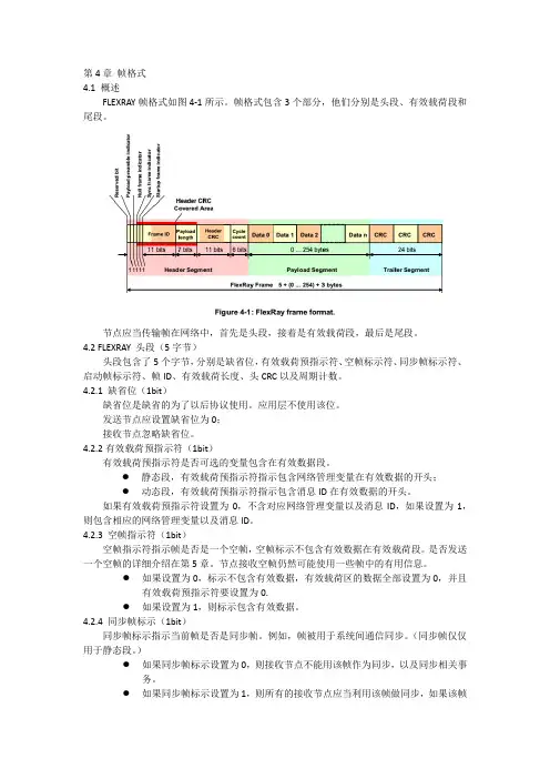
第4章帧格式4.1 概述FLEXRAY帧格式如图4-1所示。
帧格式包含3个部分,他们分别是头段、有效载荷段和尾段。
节点应当传输帧在网络中,首先是头段,接着是有效载荷段,最后是尾段。
4.2 FLEXRAY 头段(5字节)头段包含了5个字节,分别是缺省位,有效载荷预指示符、空帧标示符、同步帧标示符、启动帧标示符、帧ID、有效载荷长度、头CRC以及周期计数。
4.2.1 缺省位(1bit)缺省位是缺省的为了以后协议使用。
应用层不使用该位。
发送节点应设置缺省位为0;接收节点忽略缺省位。
4.2.2有效载荷预指示符(1bit)有效载荷预指示符是否可选的变量包含在有效数据段。
●静态段,有效载荷预指示符指示包含网络管理变量在有效数据的开头;●动态段,有效载荷预指示符指示包含消息ID在有效数据的开头。
如果有效载荷预指示符设置为0,不含对应网络管理变量以及消息ID,如果设置为1,则包含相应的网络管理变量以及消息ID。
4.2.3 空帧指示符(1bit)空帧指示符指示帧是否是一个空帧,空帧标示不包含有效数据在有效载荷段。
是否发送一个空帧的详细介绍在第5章。
节点接收空帧仍然可能使用一些帧中的有用信息。
●如果设置为0,标示不包含有效数据,有效载荷区的数据全部设置为0,并且有效载荷预指示符要设置为0.●如果设置为1,则标示包含有效数据。
4.2.4 同步帧标示(1bit)同步帧标示指示当前帧是否是同步帧。
例如,帧被用于系统间通信同步。
(同步帧仅仅用于静态段。
)●如果同步帧标示设置为0,则接收节点不能用该帧作为同步,以及同步相关事务。
●如果同步帧标示设置为1,则所有的接收节点应当利用该帧做同步,如果该帧复合其他的验收标准(见下面描述)。
时钟同步机制(详见第8章)利用同步帧标示符。
有几个条件导致同步帧指示器被设置为1,随后被利用作为时钟同步机制。
详情如何设置见第5章以及8.8节。
4.2.5 启动帧标示符(1bit)启动帧标示符指示当前帧是否是一个启动帧。

汽车控制系统效能升级!FlexRay网络标准详解自2003年组建以来,AUTOSAR(汽车开放系统架构)联盟一直致力于改变车载网络和电子控制单元(ECU)的设计方式。
AUTOSAR提出了一个符合业界标准的车载网络设计方法,使行业能够集成、交换和传输汽车网络内的功能、数据和信息。
这一标准极大地促进了汽车原始设备制造商(OEM)及其一级供应商之间的合作,使他们能够以一种一致、明确且机器可读的格式来交换设计信息。
一辆汽车的不同部分对安全及性能有不同要求,而支持它们的车载网络必须具备可预测的安全性能。
随着汽车技术的不断演变,人们已经可以用一系列总线技术来连接豪华汽车上最多100个不同的ECU,这些总线技术通常包括LIN、CAN、FlexRay、MOST和基于以太网的架构。
如果靠手动来管理这些ECU 之间数以千计的信息和交互操作是不可能的,因此汽车设计人员必然用自动化设计和合成工具来预测网络性能和调整车载功能。
汽车数据总线一辆典型的现代化汽车将同时装配各类总线和协议并从LIN、CAN、FlexRay、MOST和以太网中选择合适的网络。
多媒体/视听信号和汽车环绕摄像系统需要更高的数据速率,因此汽车制造商和OEM厂商在网络解决方案上选择用以太网代替MOST.但对于许多标准汽车功能而言,LIN和CAN提供的带宽与性能就足够了。
在汽车架构中,ECU组合在一起形成“集群”,这些集群通过通信“网关”相连。
集群通常会共享同一类型的总线,因此要达到高可靠性、高速率的标准,就要采用FlexRay 网络,但要求没那么高的门锁ECU可以由CAN或LIN来负责。
ECU网关往往要连接不同类型的信号,并执行不同总线架构之间的映射和转换功能。
汽车行业对不断提高安全性和ISO26262等标准的合规性提出强烈需求,进而提升了车载网络的性能,同时也降低了制造和元件成本。
不断进步的网络标准可以适应越来越高的数据传输速率,汽车电缆也达到了安全且低成本的目标。
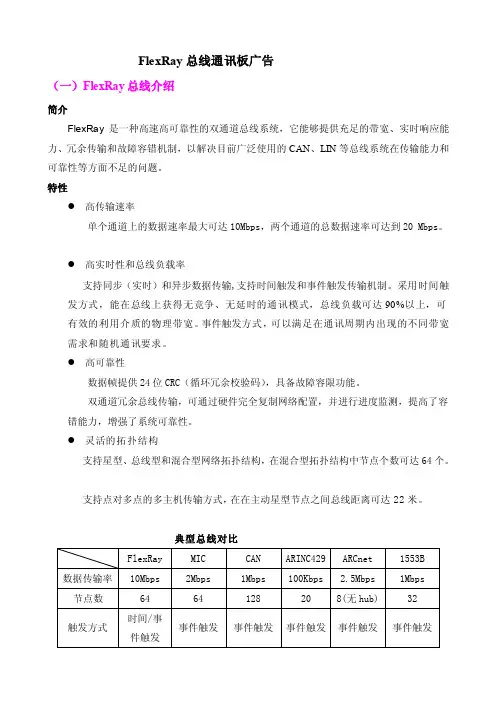
FlexRay总线通讯板广告(一)FlexRay总线介绍简介FlexRay是一种高速高可靠性的双通道总线系统,它能够提供充足的带宽、实时响应能力、冗余传输和故障容错机制,以解决目前广泛使用的CAN、LIN等总线系统在传输能力和可靠性等方面不足的问题。
特性●高传输速率单个通道上的数据速率最大可达10Mbps,两个通道的总数据速率可达到20 Mbps。
●高实时性和总线负载率支持同步(实时)和异步数据传输,支持时间触发和事件触发传输机制。
采用时间触发方式,能在总线上获得无竞争、无延时的通讯模式,总线负载可达90%以上,可有效的利用介质的物理带宽。
事件触发方式,可以满足在通讯周期内出现的不同带宽需求和随机通讯要求。
●高可靠性数据帧提供24位CRC(循环冗余校验码),具备故障容限功能。
双通道冗余总线传输,可通过硬件完全复制网络配置,并进行进度监测,提高了容错能力,增强了系统可靠性。
●灵活的拓扑结构支持星型、总线型和混合型网络拓扑结构,在混合型拓扑结构中节点个数可达64个。
支持点对多点的多主机传输方式,在在主动星型节点之间总线距离可达22米。
典型总线对比应用首个FlexRay应用产品Adaptive Drive已在BMW公司X5运动型多功能轿车上投入使用。
日本WITZ和阳光技研与瑞萨科技等公司合作,试制了采用控制类车内LAN接口标准“FlexRay”的电动车。
在未来几年中,FlexRay以汽车线控操作(X-by-Wire)为起点,将逐步覆盖到各种车辆类型的车载网络中,并推广到其它通讯控制领域,成为车辆电子和工业控制的广泛应用标准。
(二)FlexRay产品简介FlexRay总线通讯接口板1)FlexRay - PCI通讯接口板实现FlexRay总线与PCI总线之间的数据交换。
支持最新的FlexRay v2.1版协议。
两路FlexRay通道,传输速率在500Kb/s~10Mb/s之间可选。
支持FlexRay双通道冗余通讯,支持分布式多主机局域网络配置。
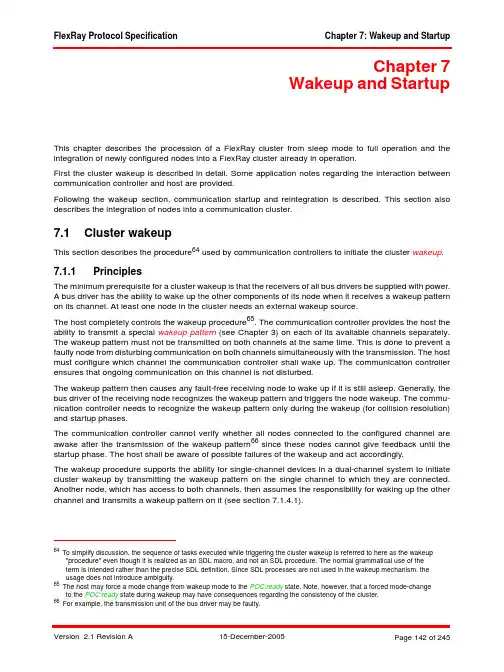
Chapter 7Wakeup and StartupThis chapter describes the procession of a FlexRay cluster from sleep mode to full operation and the integration of newly configured nodes into a FlexRay cluster already in operation.First the cluster wakeup is described in detail. Some application notes regarding the interaction between communication controller and host are provided.Following the wakeup section, communication startup and reintegration is described. This section also describes the integration of nodes into a communication cluster.7.1Cluster wakeupThis section describes the procedure64 used by communication controllers to initiate the cluster wakeup.7.1.1PrinciplesThe minimum prerequisite for a cluster wakeup is that the receivers of all bus drivers be supplied with power.A bus driver has the ability to wake up the other components of its node when it receives a wakeup pattern on its channel. At least one node in the cluster needs an external wakeup source.The host completely controls the wakeup procedure65. The communication controller provides the host the ability to transmit a special wakeup pattern (see Chapter 3) on each of its available channels separately. The wakeup pattern must not be transmitted on both channels at the same time. This is done to prevent a faulty node from disturbing communication on both channels simultaneously with the transmission. The host must configure which channel the communication controller shall wake up. The communication controller ensures that ongoing communication on this channel is not disturbed.The wakeup pattern then causes any fault-free receiving node to wake up if it is still asleep. Generally, the bus driver of the receiving node recognizes the wakeup pattern and triggers the node wakeup. The commu-nication controller needs to recognize the wakeup pattern only during the wakeup (for collision resolution) and startup phases.The communication controller cannot verify whether all nodes connected to the configured channel are awake after the transmission of the wakeup pattern66 since these nodes cannot give feedback until the startup phase. The host shall be aware of possible failures of the wakeup and act accordingly.The wakeup procedure supports the ability for single-channel devices in a dual-channel system to initiate cluster wakeup by transmitting the wakeup pattern on the single channel to which they are connected. Another node, which has access to both channels, then assumes the responsibility for waking up the other channel and transmits a wakeup pattern on it (see section 7.1.4.1).64 To simplify discussion, the sequence of tasks executed while triggering the cluster wakeup is referred to here as the wakeup"procedure" even though it is realized as an SDL macro, and not an SDL procedure. The normal grammatical use of the term is intended rather than the precise SDL definition. Since SDL processes are not used in the wakeup mechanism, the usage does not introduce ambiguity.65 The host may force a mode change from wakeup mode to the POC:ready state. Note, however, that a forced mode-changeto the POC:ready state during wakeup may have consequences regarding the consistency of the cluster.66 For example, the transmission unit of the bus driver may be faulty.The wakeup procedure tolerates any number of nodes simultaneously trying to wake up a channel and resolves this situation such that eventually only one node transmits the wakeup pattern. Additionally, the wakeup pattern is collision resilient; so even in the presence of a fault causing two nodes to simultaneously transmit a wakeup pattern the signal resulting from the collision can still wake up the other nodes.7.1.2DescriptionThe wakeup procedure is a subset of the Protocol Operation Control (POC) process. The relationship between the POC and the other protocol processes is depicted in Figure 7-167.Figure 7-1: Protocol operation control context.67 The dark lines represent data flows between mechanisms that are relevant to this chapter. The lighter gray lines are relevantto the protocol, but not to this chapter.7.1.3Wakeup support by the communication controllerThe host must initialize the wakeup of the FlexRay cluster. The host has to configure the wakeup channel pWakeupChannel while the communication controller is in the POC:config state.The host commands its communication controller to send a wakeup pattern on channel pWakeupChannel while the communication controller is in the POC:ready state. The communication controller then leaves the POC:ready state, begins the wakeup procedure (see Figure 7-2) and tries to transmit a wakeup pattern on the configured channel. Upon completion of the procedure it signals back the status of the wakeup attempt to the host (see section 9.3.1.3.1).The host must properly configure the communication controller before it may trigger the cluster wakeup. In the SDL description the wakeup procedure is realized as a macro that is called by the protocol operation control state machine (see Chapter 2).7.1.3.1Wakeup state diagramFigure 7-2: Structure of the wakeup state machine [POC].The parameter pWakeupChannel identifies the channel that the communication controller is configured to wake up. The host can only configure the wakeup channel in the POC:config state. After the communication controller has entered the POC:ready state the host can initiate wakeup on channel pWakeupChannel. Upon completing the wakeup procedure the communication controller shall return into the POC:ready state and signal to the host the result of the wakeup attempt.The return condition of the WAKEUP macro is formally defined as T_WakeupStatus in section 2.2.1.3 in Definition 2-5.The return status variable vPOC!WakeupStatus is set by the POC to•UNDEFINED, if the communication controller has not yet executed the WAKEUP mechanism since the last entry to the POC:default config state (see Figure 2-7), or when the POC responds to a CHI WAKEUP command,•RECEIVED_HEADER, if the communication controller has received a frame header without coding violation on either channel during the initial listen phase,•RECEIVED_WUP, if the communication controller has received a valid wakeup pattern on channel pWakeupChannel during the initial listen phase,•COLLISION_HEADER, if the communication controller has detected a collision during wakeup pattern transmission by receiving a valid header during the ensuing detection phase, •COLLISION_WUP, if the communication controller has detected a collision during wakeup pattern transmission by receiving a valid wakeup pattern during the ensuing detection phase,•COLLISION_UNKNOWN, if the communication controller has detected a collision but did not detecta subsequent reception event that would allow the collision to be categorized as either COLLI-SION_HEADER or COLLISION_WUP,•TRANSMITTED, if the wakeup pattern was completely transmitted.7.1.3.2The POC:wakeup listen stateFigure 7-3: Transitions from the POC:wakeup listen state [POC]68.The purpose of the POC:wakeup listen state is to inhibit the transmission of the wakeup pattern if existing communication or a startup is already in progress.68 For a single channel node, the unattached channel is assumed to always be idle.The timer tWakeup enables a fast cluster wakeup in a noise free environment, while the timer tWakeup-Noise enables wakeup under more difficult conditions when noise interference is present.When ongoing communication is detected or a wakeup of pWakeupChannel is already in progress, the wakeup attempt is aborted.7.1.3.3The POC:wakeup send stateFigure 7-4: Transitions from the state POC:wakeup send state [POC].In this state, the communication controller transmits the wakeup pattern on the configured channel and checks for collisions.Since the communication controller transmits the wakeup pattern on pWakeupChannel, it cannot really determine whether another node sends a wakeup pattern or frame on this channel during its transmission. Only during the idle portions of the wakeup pattern can it listen to the channel. If during one of these idle portions activity is detected, the communication controller leaves the send phase and enters a succeeding monitoring phase (POC:wakeup detect state) so that the cause of the collision might be identified and presented to the host.7.1.3.4The POC:wakeup detect stateFigure 7-5: Transitions from the state POC:wakeup detect state [POC].In this state, the communication controller attempts to discover the reason for the wakeup collision encoun-tered in the previous state (POC:wakeup send).This monitoring is bounded by the expiration of the timer tWakeup. The detection of either a wakeup pattern indicating a wakeup attempt by another node or the reception of a frame header indicating existing commu-nication causes a direct transition to the POC:ready state.7.1.4Wakeup application notesThe host must coordinate the bus driver and the communication controller wakeup modes. It must coordinate the wakeup of the two channels and must decide whether or not to wake a specific channel. Since proper behavior of the host is important to the wakeup procedure, the required host behavior is described here.7.1.4.1Wakeup initiation by the hostA host that wants to initiate a wakeup of the cluster should first check its bus driver(s) to see if they have received wakeup patterns. If the bus driver of a channel did not receive a wakeup pattern, and if there is no startup or communication in progress, the host shall try to wake this channel69.The host should not wake channels whose bus drivers have received a wakeup pattern unless additional information indicates that startup is not possible without an additional wakeup of those channels.70A single-channel node in a dual-channel cluster can trigger a cluster wake-up by waking its attached channel. This wakes up all nodes attached to this channel, including the coldstart nodes, which are always dual-channel. Any coldstart node that deems a system startup necessary will then wake the remaining channel before initiating communication startup.69 The host must distinguish between a local wakeup event and a remote wakeup received via the channel. This information isaccessible at the bus driver.70 This is done to speed up the wakeup process and to limit the amount of traffic on the channels, which reduces the number ofcollisions during this phase.7.1.4.1.1Single-channel nodesThis section describes the wakeup behavior of single-channel nodes in single- or dual-channel clusters. The bus driver is assumed to be in the BD_Sleep or BD_Standby mode. The host is assumed to have determined that a cluster wakeup should be triggered.1.The host first configures the communication controller. The coldstart inhibit mode71 shall be entered bysetting vColdStartInhibit to true.2.The host checks whether a wakeup pattern was received by the bus driver.3.The host puts the bus driver into the BD_Normal mode.4.If a wakeup pattern was received by the bus driver, the node should enter the startup (step 9) insteadof performing a wakeup.If no wakeup pattern received by the bus driver, the node may perform a wakeup of the attached chan-nel (which will eventually wake both channels of a dual-channel cluster).5.The host configures pWakeupChannel to the attached channel.6.The host commands the communication controller to begin the wakeup procedure.7.After its wakeup attempt is complete the communication controller returns the result of the wakeupattempt.8.The host commands the communication controller to leave the coldstart inhibit mode and to com-mence startup.7.1.4.1.2Dual-channel nodesThis section describes the wakeup behavior of dual-channel nodes in dual-channel clusters.Figure 7-6: A short example of how the wakeup of two channels can be accomplished in a fault-tolerant way by coldstart nodes.72A communication controller shall not send a wakeup pattern on both channels at the same time73. If it is necessary to wake both channels, the host can only wake them one at a time.71 This has no functional effect for non-coldstart nodes.72 Note that there is no requirement that a wakeup node be a coldstart node, or that a coldstart node be a wakeup node. In thisexample the wakeup nodes are also coldstart nodes, but this is not required.73 This requirement ensures that an erroneous communication controller cannot disturb all ongoing communication bytransmitting wakeup patterns on both channels at the same time.To avoid certain types of failures, a single communication controller should not wake up both channels. Instead, a different controller should wake up each channel.To accomplish this, a communication controller that has received a local wakeup event proceeds normally and only wakes a single channel, e.g., channel A (see Figure 7-6). Following this, it does not wake the other channel but rather enters startup. If it is a coldstart node, the coldstart inhibit flag must be set to true, so that it cannot actively initiate the cluster startup. Only after the node detects a wakeup pattern on channel B should it clear the coldstart inhibit flag and actively coldstart the cluster.Two example wakeup strategies are now given as examples to demonstrate how cluster wakeup can be accomplished. Neither strategy is concerned with the details of error recovery and therefore do not handle some error situations that are likely to occur.7.1.4.1.2.1Wakeup pattern reception by the bus driverThe bus drivers are assumed to be in the BD_Sleep or BD_Standby mode. The host is assumed to have determined that a cluster wakeup should be triggered.1.The host first configures the communication controller. It assumes both channels to be asleep. Thecoldstart inhibit mode74 shall be set.2.The host checks which of the bus drivers has received a wakeup pattern.3.The host puts all bus drivers that have received a wakeup pattern into BD_Normal mode (these chan-nels can be assumed to be awake).4.If both channels are awake, the host can proceed to startup (step 11).If both channels are asleep, the host shall wake up one of them.If one channel is asleep and one channel is awake, a non-coldstart host may wake up the channel that is asleep, but a coldstart host must wake up the channel that is asleep.5.The host configures pWakeupChannel to the channel to be awakened.6.The host activates the bus driver of pWakeupChannel.7.The host commands the communication controller to begin the wakeup procedure.8.The communication controller returns the result of the wakeup attempt.9.If the result of the wakeup attempt is TRANSMITTED, the host assumes pWakeupChannel to beawake and proceeds to startup (step 11).If the result of the wakeup attempt is RECEIVED_HEADER or COLLISION_HEADER, the host can assume that both channels are awake. It activates any remaining sleeping bus driver and proceeds to startup (step 11).If the result of the wakeup attempt is RECEIVED_WUP or COLLISION_WUP, the host assumes pWakeupChannel to be awake (return to step 4).If the result of the wakeup attempt is COLLISION_UNKOWN, an application-specific recovery strategy has to be employed, which is not covered by this document.10.The host commands the communication controller to begin the startup procedure.11.If all channels are awake, the host may command the communication controller to leave the coldstartinhibit mode. Otherwise, it waits until the bus driver of the still sleeping channel signals the reception ofa wakeup pattern. This bus driver shall then be put into the BD_Normal mode. As soon as all attachedchannels are awake, the host may command the communication controller to leave the coldstart inhibit mode.This method has the disadvantage that the channel pWakeupChannel cannot be listened to during the POC:wakeup listen state. If the bus driver of the channel is subject to an incoming link failure, ongoing communication might be disturbed and the node would not come up without additional error recovery strat-egies.74 This has no functional effect for non-coldstart nodes.7.1.4.1.2.2Wakeup pattern reception by the communication controllerThe wakeup pattern receiver of the communication controller is active as long as the CODEC is in WAKEUP mode. During this time the reception of a wakeup pattern will be directly signaled to the CHI and from there to the host.The bus drivers are assumed to be in the BD_Sleep or BD_Standby modes. The host is assumed to have determined that a cluster wakeup should be triggered.1.The host first configures the communication controller. It assumes both channels to be asleep. Thecoldstart inhibit mode75 shall be set.2.The host checks which of the bus drivers has received a wakeup pattern.3.The host puts both bus drivers into BD_Normal mode.4.If both channels are awake, the host can proceed to startup (step 10).If both channels are asleep, the host shall awake one of them.If one channel is asleep and one channel is awake, a non-coldstart host may wake up the channel that is asleep, but a coldstart host must wake up the channel that is asleep.5.The host configures pWakeupChannel to the channel that to be awakened.6.The host commands the communication controller to begin the wakeup procedure.7.The communication controller returns the result of the wakeup attempt.8.If the result of the wakeup attempt is TRANSMITTED, the host assumes pWakeupChannel to beawake and proceeds to startup (step 10).If the result of the wakeup attempt is RECEIVED_HEADER or COLLISION_HEADER, the hostassumes all attached channels to be awake and proceeds to startup (step 10).If the result of the wakeup attempt is RECEIVED_WUP or COLLISION_WUP, the host assumes pWakeupChannel to be awake (return to step 4).If the result of the wakeup attempt is COLLISION_UNKOWN, an application-specific recovery strategy has to be employed, which is not covered here.9.The host commands the communication controller to begin the startup procedure.10.If all channels are awake, the host may command the communication controller to leave the coldstartinhibit mode. Otherwise, it waits until the wakeup pattern receiver of the communication controller detects a wakeup pattern on the channel that is assumed to be asleep (this could already haveoccurred during one of the former steps). If the communication controller internal wakeup pattern detector receives a wakeup pattern on this channel, it is further assumed to be awake. As soon as all attached channels are awake, the host may command the communication controller to leave the cold-start inhibit mode.7.1.4.2Host reactions to status flags signaled by the communicationcontrollerThis section defines the status information that the communication controller can return to the host as result of its wakeup attempt and the recommended reaction of the host.7.1.4.2.1Frame header reception without coding violationWhen a frame header without coding violation is received by the communication controller on either available channel while in the POC:wakeup listen (or POC:wakeup detect) state the communication controller aborts the wakeup, even if channel pWakeupChannel is still silent.The host shall not command the communication controller to initiate additional wakeup attempts, since this could disturb ongoing communication. Instead, it shall command the communication controller to enter the startup to integrate into the apparently established cluster communication.75 This has no functional effect for non-coldstart nodes.7.1.4.2.2Wakeup pattern receptionThe communication controller has received a wakeup pattern on channel pWakeupChannel while in the POC:wakeup listen (or POC:wakeup detect) state. This indicates that another node is already waking up this channel. To prevent collisions of wakeup patterns on channel pWakeupChannel, the communication controller aborts the wakeup.If another channel is available that is not already awake, the host must determine whether the communi-cation controller is to wake up this channel. If all available channels are awake, the host shall command the communication controller to enter startup.7.1.4.2.3Wakeup pattern transmissionThe communication controller has transmitted the complete wakeup pattern on channel pWakeupChannel. The node can now proceed to startup. In a dual-channel cluster, coldstart nodes may need to be put into the coldstart inhibit mode (see section 7.1.4.1).7.1.4.2.4Termination due to unsuccessful wakeup pattern transmissionThe communication controller was not able to transmit a complete wakeup pattern because its attempt to transmit it resulted in at least cdWakeupMaxCollision occurrences of continuous logical LOW during the idle phase of a wakeup pattern. Possible reasons for this are heavy EMC disturbances on the bus or an internal error.76Since no complete wakeup pattern has been transmitted, it cannot be assumed that all nodes have receiveda wakeup pattern. The host may use the retransmission procedure described in section 7.1.4.3.7.1.4.3Retransmission of wakeup patternsSome events or conditions may prevent a cluster from waking up even though a wakeup attempt has been made (possibly even without the transmitting communication controller being able to immediately detect this failure77). The host detects such an error when the cluster does not start up successfully after the wakeup.The host may then initiate a retransmission of the wakeup pattern. The procedure described in section 7.1.2 shall be used to transmit a wakeup pattern on channel pWakeupChannel.Note that this might disturb ongoing communication of other nodes if the node initiating the wakeup procedure is subject to an incoming link failure or a fault in the communication controller. The host must ensure that such a failure condition will not lead to a permanent disturbance on the bus.7.1.4.4Transition to startupIt cannot be assumed that all nodes and stars need the same amount of time to become completely awake and to be configured.Since at least two nodes are necessary to start up the cluster communication, it is advisable to delay any potential startup attempt of the node having initiating the wakeup by the minimal amount of time it takes another coldstart node to become awake, to be configured, and to enter startup78. Otherwise, the wakeup-initiating coldstart node may fail in its startup attempt with an error condition that is not distinguishable froma defective outgoing link (the communication controller reports no communication partners; see section7.1.4.3).76 The collision of a wakeup pattern transmitted by this node with another wakeup pattern generated by a fault-free node willgenerally not result in this exit condition. Such a collision can be recognized after entering the POC:wakeup detect state and would be signaled by setting the variable vPOC!WakeupStatus to COLLISION_WUP.77 E.g. an erroneous star that needs significantly more time to start up and to be able to forward messages.78 This parameter depends heavily on implementation details of the components used and the ECU structure.The vColdstartInhibit flag can be used to effectively deal with this situation. A communication controller with this flag set to true will only participate in the startup attempts made by other nodes but not initiate one itself. The host should not clear this flag before the above mentioned minimal time for another node to become ready for the communication startup. However, the host shall clear it as soon as all coldstart nodes are awake in the fault-free case79. Please refer to section 7.2.2 for further details of this flag.7.2Communication startup and reintegrationA TDMA based communication scheme requires synchrony and alignment of all nodes that participate in cluster communication. A fault-tolerant, distributed startup strategy is specified for initial synchronization of all nodes. This strategy is described in the following subsections.7.2.1Principles7.2.1.1Definition and propertiesBefore communication startup can be performed, the cluster has to be awake, so the wakeup procedure has to be completed before startup can commence. The startup is performed on all channels synchronously.The action of initiating a startup process is called a coldstart. Only a limited number of nodes may initiate a startup, they are called the coldstart nodes.A coldstart attempt begins with the transmission of a collision avoidance symbol (CAS). Only the coldstart node that transmits the CAS transmits frames in the first four cycles after the CAS. It is then joined first by the other coldstart nodes and afterwards by all other nodes.A coldstart node has the configuration parameter pKeySlotUsedForStartup set to true and is configured with a frame header containing a startup frame indicator set to one (see Chapter 4). In each cluster consisting of at least three nodes, at least three nodes shall be configured to be coldstart nodes80. In clusters consisting of less than three nodes, each node shall be a coldstart node. Each startup frame shall also be a sync frame; therefore each coldstart node will also be a sync node. The parameter gColdStartAttempts shall be configured to be at least two. At least two fault-free coldstart nodes are necessary for the cluster to start up.A coldstart node that actively starts the cluster is also called a leading coldstart node. A coldstart node that integrates upon another coldstart node is also called a following coldstart node.A node is in "startup" if its protocol operation control machine is in one of the states contained in the STARTUP macro (vPOC!State is set to STARTUP during this time, see Chapter 2). During startup, a node may only transmit startup frames. Any coldstart node shall wake up the cluster or determine that it is already awake before entering startup (see section 7.1.4).7.2.1.2Principle of operationThe system startup consists of two logical steps. In the first step dedicated coldstart nodes start up. In the second step the other nodes integrate to the coldstart nodes.7.2.1.2.1Startup performed by the coldstart nodes•Only the coldstart nodes can initiate the cluster start up.•Each of the coldstart nodes finishes its startup as soon as stable communication with one of the other coldstart nodes is established.79 If these times are not known at system design time, it is advised to clear the flag late rather than early.80 This does not imply any restrictions concerning which nodes may initiate a cluster wakeup.7.2.1.2.2Integration of the non-coldstart nodes• A non-coldstart node requires at least two startup frames from distinct nodes for integration. This condition ensures that each non-coldstart node always joins the majority of the coldstart nodes81.•Integrating non-coldstart nodes may start their integration before coldstart nodes have finished their startup.•Integrating non-coldstart nodes may not finish their startup until at least two coldstart nodes have finished their startup.7.2.2DescriptionThe startup procedure is a subset of the Protocol Operation Control (POC) process. The relationship between the POC and the other protocol processes is depicted in Figure 7-7.Figure 7-7: Protocol operation control context.81 This is the case under the assumption that the cluster contains exactly the three recommended coldstart nodes.。
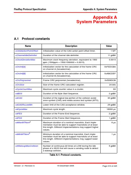
Appendix ASystem ParametersA.1Protocol constantsName Description Value cCASActionPointOffset Initialization value of the CAS action point offset timer. 1 MT cChannelIdleDelimiter Duration of the channel idle delimiter.11 gdBit cClockDeviationMax Maximum clock frequency deviation, equivalent to 15000.0015ppm (1500ppm = 1500/1000000 = 0.0015).0xFEDCBA cCrcInit[A]Initialization vector for the calculation of the frame CRCon channel A (hexadecimal).cCrcInit[B]Initialization vector for the calculation of the frame CRC0xABCDEFon channel B (hexadecimal).cCrcPolynomial Frame CRC polynomial (hexadecimal).0x5D6DCB cCrcSize Size of the frame CRC calculation register.24 bits cCycleCountMax Maximum cycle counter value in a cluster.63 cdBSS Duration of the Byte Start Sequence. 2 gdBit30 gdBit cdCAS Duration of the logical low portion of the collision avoid-ance symbol (CAS) and media access test symbol (MTS). cdCASRxLowMin Lower limit of the CAS acceptance window.29 gdBit cdCycleMax Maximum cycle length.16000 µs cdFES Duration of the Frame End Sequence. 2 gdBit cdFSS Duration of the Frame Start Sequence. 1 gdBit cdMaxMTNom a Maximum duration of a nominal macrotick. Each imple-6 µsmentation must be able to support macroticks of at leastthis length. Different implementations may support highervalues.1 µs cdMinMTNom b Minimum duration of a nominal macrotick. Each imple-mentation must be able to support macroticks of at leastthis length. Different implementations may support lowervalues.5 gdBit cdWakeupMaxCollision Number of continuous bit times at LOW during the idlephase of a WUS that will cause a sending node to detecta wakeup collision.Table A-1: Protocol constants.A.1.1cdCASRxLowMinThe lower limit of the acceptance window for a collision avoidance symbol (CAS) must meet the following constraint:Constraint 1:cdCASRxLowMin [gdBit]= floor( cdCAS [gdBit] * (1 - cClockDeviationMax ) / (1 + cClockDeviationMax ) )= 29 gdBitAs a result, the constant cdCASRxLowMin is 29 gdBit.cdWakeupSymbolTxLow Duration of low phase of a transmitted wakeup symbol. 6 µs cdWakeupSymbolTxIdle Duration of the idle phase between two low phases inside a wakeup pattern.18 µs cHCrcInit Initialization vector for the calculation of the header CRC on channel A or channel B (hexadecimal).0x01A cHCrcPolynomial Header CRC polynomial (hexadecimal).0x385cHCrcSizeSize of header CRC calculation register.11 bitscPayloadLengthMax Maximum length of the payload segment of a frame.127 two-byte-wordscMicroPerMacroMin Minimum number of microticks per macrotick during the offset correction phase.20 µT cMicroPerMacroNomMin Minimum number of microticks in a nominal (uncorrected) macrotick.40 µT cMicroPerMacroNomMax Maximum number of microticks in a nominal (uncor-rected) macrotick.240 µTcSamplesPerBit Number of samples taken in the determination of a bit value.8cSlotIDMax Highest slot ID number.2047cStaticSlotIDMax Highest static slot ID number.1023cStrobeOffset Sample where bit strobing is performed (first sample of a bit is considered as sample 1).5cSyncNodeMax Maximum number of sync nodes in a cluster.15cVotingDelay Number of samples of delay between the RxD input and the majority voted output in the glitch-free case.(cVotingSam-ples -1) / 2cVotingSamplesNumbers of samples in the voting window used for major-ity voting of the RxD input.5a This parameter is only introduced to be able to define a minimum conformance class range that all implementations mustsupport.bThis parameter is only introduced to be able to define a minimum conformance class range that all implementations must support.NameDescriptionValueTable A-1: Protocol constants.A.2Physical layer constantsAdditional parameters related to the Electrical Physical Layer and active/passive stars may be found in [EPL05].A.2.1cdTxMaxThe value of cdTxMax can be determined in the following way:Constraint 2:cdTxMax = max( adTxMax )To calculate the maximum of adTxMax the longest possible frames are taken into account (aFrame-LengthStatic Max = aFrameLengthDynamic Max , see B.4.9).[1]adTxMax [µs] >= (aFrameLengthStatic [gdBit] + 2 gdBit) * gdBitMax [µs/gdBit] +gdMinislot [MT] * gdMacrotick [µs/MT] * (1 + cClockDeviationMax )As a result, cdTxMax is 1433 µs.NameDescriptionValue cPropagationDelayMaxMaximum propagation delay from the falling edge (in the BSS) in the transmit signal of node M to corresponding falling edge at the receiver of node N.2.5 µscdTxMax aaThe value of cdTxMax is the lower bound of dBranchActive in [EPL05].Longest possible period of continuous transmission activity for a valid FlexRay configuration.1433 µsTable A-2: Physical layer constants.Bit Rate [MBit/s]2.5510aFrameLengthStatic Max [gdBit]262826312638gdBitMax [µs]0.40060.20030.10015gdMinislot Max [µs]63gdMacrotick Max [µs]6adTxMax [µs]1433906643Table A-3: Calculation of maximum values for adTxMax .A.3Performance ConstantsTable A-4: Performance constants.NameDescriptionValue cdMaxOffsetCalculationMaximum time allowed for calculation of the offset correction value, measured from the end of the static segment. In some situations the offset correction calculation deadline is actually longer - see section 8.6.2 for details.1350 µTcdMaxRateCalculation Maximum time allowed for calculation of the rate correction value, measured from the end of the static segment. In some situations the rate correction calculation deadline is actually longer - see section 8.6.3 for details.1500 µTAppendix BConfiguration ConstraintsB.1GeneralThis appendix specifies the configurable parameters of the FlexRay protocol. This appendix also identifies the configurable range of the parameters, and gives constraints on the values that the parameters may take on. The listed parameters will be part of the definition of FlexRay conformance classes.113 All implementa-tions that support a given parameter must support at least the parameter range identified in this appendix.An implementation is allowed, however, to support a broader range of configuration values.Currently the only bit rate defined for FlexRay is 10 Mbit/s. There is, however, the intent that the protocol will be expanded in the future to include bit rates lower than 10 Mbit/s. The configuration ranges shown in this appendix reflect bit rates of between 2.5 Mbit/s and 10 Mbit/s. Changes in the range of supported bit rates would also change the required configuration ranges of some parameters. Also, this range should not be interpreted as indicating that all possible bit rates between 2.5 Mbit/s and 10 Mbit/s would be acceptable.B.2Global cluster parametersB.2.1Protocol relevantProtocol relevant global cluster parameters are parameters used within the SDL models to describe the FlexRay protocol. They must have the same value in all nodes of a cluster.113Exceptions for parameters which should not be part of a conformance class are indicated by footnote.NameDescriptionRangegColdStartAttemptsMaximum number of times a node in the cluster is permit-ted to attempt to start the cluster by initiating schedule synchronization.2 - 31gdActionPointOffset Number of macroticks the action point is offset from the beginning of a static slot or symbol window. 1 - 63 MT gdCASRxLowMax Upper limit of the CAS acceptance window.67 - 99 gdBit gdDynamicSlotIdlePhase Duration of the idle phase within a dynamic slot.0 - 2 Minislot gdMinislotDuration of a minislot.2 - 63 MT gdMinislotActionPoint-Offset Number of macroticks the minislot action point is offset from the beginning of a minislot. 1 - 31 MT gdStaticSlot Duration of a static slot.a4 - 661 MT gdSymbolWindow Duration of the symbol window.0 - 142 MT gdTSSTransmitterNumber of bits in the Transmission Start Sequence. 3 - 15 gdBitTable B-1: Global protocol relevant parameters.gdWakeupSymbolRxIdle Number of bits used by the node to test the duration of the'idle' portion of a received wakeup symbol. Duration isequal to (gdWakeupSymbolTxIdle - gdWakeupSym-bolTxLow)/2 minus a safe part. (Collisions, clock differ-ences, and other effects can deform the Tx-wakeuppattern.)14 - 59 gdBitgdWakeupSymbolRxLow Number of bits used by the node to test the LOW portionof a received wakeup symbol. This lower limit of zero bitshas to be received to detect the LOW portion by thereceiver. The duration is equal to gdWakeupSym-bolTxLow minus a safe part. (Active stars, clock differ-ences, and other effects can deform the Tx-wakeuppattern.)11 - 59 gdBitgdWakeupSymbolRx-Window The size of the window used to detect wakeups. Detectionof a wakeup requires a low and idle period (from oneWUS) and a low period (from another WUS) to bedetected entirely within a window of this size. The durationis equal to gdWakeupSymbolTxIdle + 2 * gdWakeupSym-bolTxLow plus a safe part. (Clock differences and othereffects can deform the Tx-wakeup pattern.)76 - 301 gdBitgdWakeupSymbolTxIdle Number of bits used by the node to transmit the 'idle' partof a wakeup symbol. The duration is equal to cdWake-upSymbolTxIdle.45 - 180 gdBitgdWakeupSymbolTxLow Number of bits used by the node to transmit the LOWpart of a wakeup symbol. The duration is equal tocdWakeupSymbolTxLow.15 - 60 gdBitgListenNoise Upper limit for the startup listen timeout and wakeup lis-ten timeout in the presence of noise. It is used as a multi-plier of the node parameter pdListenTimeout.2 - 16gMacroPerCycle Number of macroticks in a communication cycle.10 - 16000MTgMaxWithoutClockCor-rectionFatal Threshold used for testing the vClockCorrectionFailedcounter. Defines the number of consecutive even/oddcycle pairs with missing clock correction terms that willcause the protocol to transition from the POC:normalactive or POC:normal passive state into the POC:haltstate.gMaxWithout-ClockCorrec-tionPassive -15 even/oddcycle pairsgMaxWithoutClockCor-rectionPassive Threshold used for testing the vClockCorrectionFailedcounter. Defines the number of consecutive even/oddcycle pairs with missing clock correction terms that willcause the protocol to transition from the POC:normalactive state to the POC:normal passive state. Note that gMaxWithoutClockCorrectionPassive <= gMaxWithout-ClockCorrectionFatal <= 15.1 - 15 even/odd cyclepairsgNumberOfMinislots Number of minislots in the dynamic segment.0 - 7986Table B-1: Global protocol relevant parameters.B.2.2Protocol relatedProtocol related global cluster parameters are parameters that have a meaning in the context of the FlexRay protocol but are not used within the SDL models. These parameters are used in the configuration constraints. They must have the same value in all nodes of a cluster.gNumberOfStaticSlots Number of static slots in the static segment.2 - cStatic-SlotIDMax gOffsetCorrectionStartStart of the offset correction phase within the NIT,expressed as the number of macroticks from the start of cycle.9 - 15999 MTgPayloadLengthStaticPayload length of a static frame.b0 - cPayload-LengthMax two-byte-words gSyncNodeMaxMaximum number of nodes that may send frames with the sync frame indicator bit set to one.2 - cSyncNo-deMaxa This parameter is also used in the FlexRay Electrical Physical Layer Specification [EPL05].bAll static frames in a cluster have the same payload length.NameDescriptionRange gAssumedPrecision Assumed precision of the application network.0.15 - 11.7 µs gChannelsThe channels that are used by the cluster.[A, B, A&B]gClusterDriftDampingThe cluster drift damping factor, based on the longest microtick gdMaxMicrotick used in the cluster. Used to compute the local cluster drift damping factor pCluster-DriftDamping .0 - 5 µTgdBitNominal bit time (see formula [7]).cSamplesPerBit *gdSampleClock-Period [µs]gdBitMax a Maximum bit time taking into account the allowable clock deviation of each node.gdBit * (1 + cClock-DeviationMax ) [µs]gdBitMin b Minimum bit time taking into account the allowable clock deviation of each node.gdBit * (1 - cClock-DeviationMax ) [µs]gdCycle Length of the cycle, expressed in µs.10 µs c -cdCycleMaxgdMacrotick Duration of the cluster wide nominal macrotick, expressed in µs (see formula [8]).1 - 6 µs gdMaxInitialization-ErrorMaximum timing error that a node may have following integration.0 - 11.7 µsTable B-2: Global protocol related parameters.Table B-1: Global protocol relevant parameters.B.2.3Physical layer relevantFor detailed information refer to [EPL05].B.3Node parametersB.3.1Protocol relevantProtocol relevant node parameters are parameters used within the SDL models to describe the FlexRay protocol. They may have different values in different nodes of a cluster.gdMaxMicrotick d Maximum microtick length of all microticks configured within a cluster (see formula [2]).pdMicrotick [µs]gdMaxPropagation-DelayMaximum propagation delay of a cluster (see Con-straint 3).<= cPropagation-DelayMax [µs]gdMinPropagation-Delay Minimum propagation delay of a cluster.<= gdMaxPropa-gationDelay [µs]gdNITDuration of the Network Idle Time. 2 - 805 MT gdSampleClockPeriod Sample clock period.[0.0125, 0.025,0.05 µs]gNetworkManage-mentVectorLength Length of the Network Management vector in a cluster.0 - 12 bytes gOffsetCorrectionMaxCluster global magnitude of the maximum necessary offset correction value.0.15 - 383.567 µsa This parameter is only introduced for configuration constraints.b This parameter is only introduced for configuration constraints.cSee the minimum constraint for gMacroPerCycle . Maximum value is given by cdCycleMax .dThis parameter is only introduced for configuration constraints.NameDescriptionRange pAllowHaltDueToClockBoolean flag that controls the transition to the POC:halt state due to a clock synchronization errors. If set to true, the CC is allowed to transition to POC:halt .If set to false, the CC will not transition to the POC:halt state but will enter or remain in the POC:normal pas-sive state (self healing would still be possible).BooleanpAllowPassiveToActiveNumber of consecutive even/odd cycle pairs that must have valid clock correction terms before the CC will be allowed to transition from the POC:normal passive state to POC:normal active state. If set to zero, the CC is not allowed to transition from POC:normal passive to POC:normal active .0 - 31 even/oddcycle pairsTable B-3: Local node protocol relevant parameters.Table B-2: Global protocol related parameters.pChannels Channels to which the node is connected.[A, B, A&B]pdAcceptedStartu-pRange Expanded range of measured clock deviation allowedfor startup frames during integration.0 - 1875 µTpClusterDriftDamping Local cluster drift damping factor used for rate correc-tion.0 - 20 µTpDecodingCorrection Value used by the receiver to calculate the differencebetween primary time reference point and secondarytime reference point.14 - 143 µTpDelayCompensa-tion[A], pDelayCompen-sation[B]Value used to compensate for reception delays on theindicated channel. This covers assumed propagationdelay up to cPropagationDelayMax for microticks in therange of 0.0125 µs to 0.05 µs.In practice, the minimum of the propagation delays ofall sync nodes should be applied.0 - 200 µTpdListenTimeout Value for the startup listen timeout and wakeup listentimeout. Although this is a node local parameter, thereal time equivalent of this value should be the samefor all nodes in the cluster.1284 - 1283846µTpdMaxDrift Maximum drift offset between two nodes that operatewith unsynchronized clocks over one communicationcycle.2 - 1923 µTpExternOffsetCorrection Number of microticks added or subtracted to the NIT tocarry out a host-requested external offset correction.0 - 7 µTpExternRateCorrection Number of microticks added or subtracted to the cycleto carry out a host-requested external rate correction.0 - 7 µTpKeySlotId ID of the slot used to transmit the startup frame, syncframe, or designated single slot frame.1 - cStaticSlot-IdMaxpKeySlotUsedForStartup Flag indicating whether the Key Slot is used to transmita startup frame. If pKeySlotUsedForStartup is set totrue then pKeySlotUsedForSync must also be set totrue.BooleanpKeySlotUsedForSync Flag indicating whether the Key Slot is used to transmita sync frame. If pKeySlotUsedForStartup is set to truethen pKeySlotUsedForSync must also be set to true.BooleanpLatestTx Number of the last minislot in which a frame transmis-sion can start in the dynamic segment.0 - 7980 MinislotpMacroInitialOffset[A], pMacroInitialOffset[B]Integer number of macroticks between the static slotboundary and the following macrotick boundary of thesecondary time reference point based on the nominalmacrotick duration.2 - 68 MT Table B-3: Local node protocol relevant parameters.B.3.2Protocol relatedProtocol related node parameters are parameters that have a meaning in the context of the FlexRay protocol but are not used within the SDL models. They may have different values in different nodes of a cluster.pMicroInitialOffset[A], pMicroInitialOffset[B]Number of microticks between the closest macrotick boundary described by pMacroInitialOffset[Ch] and the secondary time reference point.The parameter depends on pDelayCompensation[Ch] and therefore it has to be set independently for each channel.0 - 239 µTpMicroPerCycle Nominal number of microticks in the communication cycle of the local node. If nodes have different microtick durations this number will differ from node to node.640 - 640000 µTpOffsetCorrectionOut Magnitude of the maximum permissible offset correc-tion value.13 - 15567 µT pRateCorrectionOut Magnitude of the maximum permissible rate correction value.2 - 1923 µT pSingleSlotEnabled Flag indicating whether or not the node shall enter sin-gle slot mode following startup.Boolean pWakeupChannel Channel used by the node to send a wakeup pattern.[A, B]pWakeupPatternNumber of repetitions of the wakeup symbol that are combined to form a wakeup pattern when the node enters the POC:wakeup send state.2 - 63NameDescriptionRangepdMicrotick aa Shall not be part of the conformance test due to implementation dependency.Duration of a microtick.pSamplesPerMicrotick *gdSampleClockPeriod [µs]pMicroPerMacroNom Number of microticks per nominal macrotick that all implementations must support.cMicroPerMacroNomMin -cMicroPerMacroNomMax pPayloadLengthDynMax Maximum payload length for dynamic frames.0 - cPayloadLengthMaxpSamplesPerMicrotick bbShall not be part of the conformance test due to implementation dependency.Number of samples per microtick.[1, 2, 4]Table B-4: Local node protocol related parameters.Table B-3: Local node protocol relevant parameters.B.3.3Physical layer relevantFor values of the following parameter please refer to [EPL05].Name DescriptiondStarTruncation Interval by which a transmitted TSS is shortened by one star.nStarPath M,N Number of stars on the signal path from any node M to a node N in anetwork with active stars.dBDRxia Activity reaction time. Time by which a transmission becomes short-ened in a receiving node (when bus is switched from idle to active).dBDRxai Idle reaction time. Time by which a transmission becomes lengthenedin a receiving node (when bus is switched from active to idle). If the lastactive driven bit was HIGH the idle detection in the CC is not delayed.dBDTxia Activity reaction time. Time by which a transmission becomes short-ened in a transmitting node (when bus is switched from idle to active).dBDTxai Idle reaction time. Time by which a transmission becomes lengthenedin a transmitting node (when bus is switched from active to idle).dBDRx01Time by which a positive edge is delayed in a receiving node.dBDRx10Time by which a negative edge is delayed in a receiving node.dBDTx01Time by which a positive edge is delayed in a transmitting node.dBDTx10Time by which a negative edge is delayed in a transmitting node.Table B-5: Local node physical layer related parameters.B.4Calculation of configuration parametersFollowing abbreviations and functions are used in this section:1.Function ceil(x) returns the nearest integer greater than or equal to x.2.Function floor(x) returns the nearest integer less than or equal to x.3.Function max(x;y) returns the maximum value from a set of values {x;y}.4.Function min(x;y) returns the minimum value from a set of values {x;y}.5.Function round(x) returns the rounded integer value of x.6.Function if(c;x;y) returns x if condition c is true, otherwise y.7.[ ] denotes units.B.4.1Attainable precisionVarious error terms influence the attainable precision of the FlexRay clock synchronization algorithm (see [Mül01] and [Ung02]). In order to choose proper configuration parameters it is necessary to know the attainable precision of the application network.B.4.1.1Propagation DelayA parameter for the maximum propagation delay gdMaxPropagationDelay[µs] of the cluster is introduced withConstraint 3:gdMaxPropagationDelay[Ch][µs] = max( pdBDTx[Ch]M [µs] + LineLength[Ch]M,N [m] * T 0[µs/m] +[µs] + pdBDRx[Ch]N [µs] )M,N gdMaxPropagationDelay [µs] = max( gdMaxPropagationDelay[A][µs], gdMaxPropagationDelay[B][µs] )<= cPropagationDelayMaxmax(...)M,N means the maximum of all paths from node M to node N with M,N = 1, .., number of nodes andM <> N.•pdBDTx[Ch]M is the maximum propagation delay of the transmitter of node M on Channel Ch and represents the maximum of the propagation delay of a positive edge (dBDTx01) and a negative edge (dBDTx10) inside the transmitter•pdBDRx[Ch]N is the maximum propagation delay of the receiver of node N on Channel Ch and represents the maximum of the propagation delay of a positive edge (dBDRx01) and a negative edge (dBDRx10) inside the receiver.•pdStarDelay k is the propagation delay of star k .•LineLength[Ch]M,N is the real line length between node M and node N on Channel Ch .•{nStar[Ch]MN } is the number of active stars between node M and N on Channel Ch .•The propagation delay per unit length of a line T 0 is approximately 0.01µs/m.The value of gdMaxPropagationDelay should be estimated for the given network topology using the estimated propagation delays of line, star and transmitter. If this is not possible or a worst case estimation is needed, a value from Table B-6 should be chosen. The gdMaxPropagationDelay Max parameter from Table B-6 is also used to derive additional constraints on other parameters.In some cases the propagation delay of a star may be up to 0.7µs (if, for example, the star includes a signal refresh feature). It is acceptable to use a star with this increased propagation delay if the overall propagation delay gdMaxPropagationDelay is always less than or equal to the upper limit of cPropagationDelayMax .B.4.1.2Worst-case precisionFirst of all, a parameter defining the maximum used microtick of a cluster is introduced:[2]gdMaxMicrotick [µs] = max( { x | x = pdMicrotick of each node } )The worst-case error before the correction is given bynStar 012LineLength [m]244872pdBDTx Max [µs]0.1pdBDRx Max [µs]0.1pdStarDelay Max [µs]0.25gdMaxPropagationDelay Max [µs]0.440.931.42Table B-6: Maximum propagation delay in a cluster. Maximum values for LineLength , pdBDTx ,pdBDRx and pdStarDelay were chosen according to limits described in [EPL05].pdStarDelay kk nStar Ch []MN {}∈∑[3]aWorstCasePrecision [µs] = (34 µT + 20 * gClusterDriftDamping [µT]) * gdMaxMicrotick [µs/µT] +2 * gdMaxPropagationDelay [µs]It is important to note that the attainable precision directly depends on network topology (gdMaxPropaga-tionDelay ) and the maximum microtick used in the cluster (gdMaxMicrotick ).As explained in [Mül01] and [Ung02], it can be proven that a value of gClusterDriftDamping = 5 µT is enough to prevent cluster drifts. Since cluster precision becomes worse as gClusterDriftDamping increases, gClus-terDriftDamping is limited to 5 µT.Table B-7: Calculation of the worst-case precision.For further parameter calculations it is assumed that gdMaxMicrotick [µs] = 0.05 µs or a smaller value.Therefore the worst-case precision is assumed to be 11.7 µs.B.4.1.3Best-case precisionThe best-case precision can be calculated using a simplified equation [3] which does not take Byzantine errors into account.[4]aBestCasePrecision [µs] >= (12 µT + 6 * gClusterDriftDamping [µT]) * gdMaxMicrotick [µs/µT] +gdMaxPropagationDelay [µs] - gdMinPropagationDelay [µs]It is not possible to reach a precision better than calculated in [4].Table B-8: Calculation of the best-case precision.B.4.1.4Assumed precisionAn assumed precision of the cluster, gAssumedPrecision [µs] is introduced. This parameter depends on the parameters gdMaxPropagationDelay , gdMaxMicrotick and gClusterDriftDamping . The gAssumedPrecision parameter is necessary to derive additional constraints on other timing parameters. This parameter is given byConstraint 4:aBestCasePrecision [µs] <= gAssumedPrecision [µs] <= aWorstCasePrecision [µs]gdMaxMicrotick [µs]0.1000.0500.0250.0125gClusterDriftDamping Max [µT]5gdMaxPropagationDelay [µs] = cPropagationDelayMax [µs] 2.5aWorstCasePrecision Max [µs]18.411.78.356.675gdMaxMicrotick [µs]0.1000.0500.0250.0125gClusterDriftDamping Min [µT]0min( gdMaxPropagationDelay [µs] - gdMinPropagationDelay [µs] )0aBestCasePrecision Min [µs]1.20.60.30.15For purposes of configuration of the cluster, it is suggested that gAssumedPrecision should be:[5]gAssumedPrecision [µs] = aWorstCasePrecision [µs] = (34 µT + 20 * gClusterDriftDamping [µT])* gdMaxMicrotick [µs/µT] +2 * gdMaxPropagationDelay [µs]B.4.2Definition of microtick and macrotickThe parameter pdMicrotick is usually not a configuration parameter of an implementation. It is introduced here because it is used to derive various parameter constraints.The microtick length (pdMicrotick ) is implementation dependent and may be different for each node. The bit length (gdBit ) must be identical for all nodes of the cluster. Both parameters are defined in multiples of the sample clock period.[6] pdMicrotick = pSamplesPerMicrotick * gdSampleClockPeriod [7]gdBit = cSamplesPerBit * gdSampleClockPeriodTable B-9 shows the possible microtick lengths depending on pSamplesPerMicrotick and gdSampleClock-Period . Table B-10 shows the possible nominal macrotick lengths (gdMacrotick ) on a range of the microticks per macrotick parameter (pMicroPerMacroNom ) of between 40 to 240. In practice, it is assumed that the typical microtick range is pdMicrotick = 0.0125 µs ... 0.05 µs because of this parameter's direct influence to the attainable precision.Table B-9: pdMicrotick [µs] depending on pSamplesPerMicrotick and gdSampleClockPeriod .Table B-10: gdMacrotick [µs] depending on pMicroPerMacroNom and pdMicrotick .Some parameter constraints depend on the microtick length of the node and the nominal macrotick length of the cluster. To define a minimum parameter range for these parameters, that is the basis of conformance tests, a typical microtick length of 0.025 µs and the resulting nominal macrotick range of 1 µs to 6 µs (Constraint 5) are assumed (green fields within Table B-9 and B-10).gdSample-ClockPeriod [µs]pSamplesPerMicrotick 1240.01250.01250.0250.0500.02500.0250.0500.1000.05000.0500.100-pMicroPer-MacroNompdMicrotick [µs]0.01250.0250.0500.10040-12460- 1.53680124-1201.536-24036--。
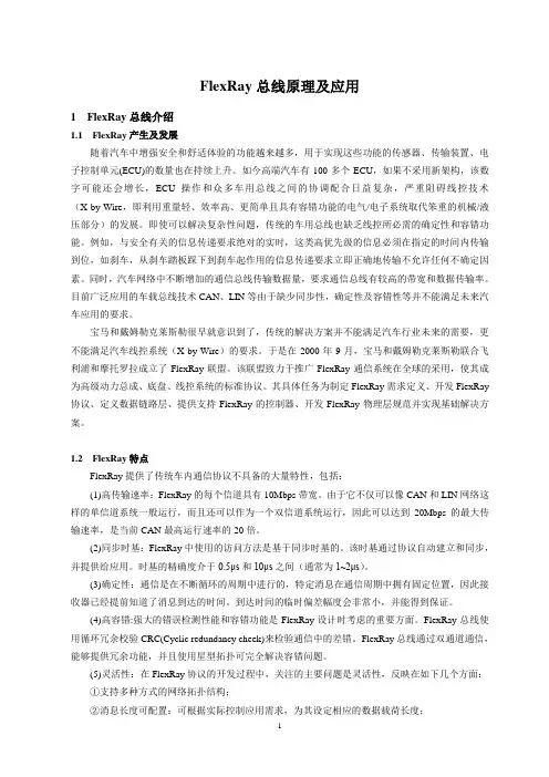
FlexRay总线原理及应用1 FlexRay总线介绍1.1 FlexRay产生及发展随着汽车中增强安全和舒适体验的功能越来越多,用于实现这些功能的传感器、传输装置、电子控制单元(ECU)的数量也在持续上升。
如今高端汽车有100多个ECU,如果不采用新架构,该数字可能还会增长,ECU操作和众多车用总线之间的协调配合日益复杂,严重阻碍线控技术(X-by-Wire,即利用重量轻、效率高、更简单且具有容错功能的电气/电子系统取代笨重的机械/液压部分)的发展。
即使可以解决复杂性问题,传统的车用总线也缺乏线控所必需的确定性和容错功能。
例如,与安全有关的信息传递要求绝对的实时,这类高优先级的信息必须在指定的时间内传输到位,如刹车,从刹车踏板踩下到刹车起作用的信息传递要求立即正确地传输不允许任何不确定因素。
同时,汽车网络中不断增加的通信总线传输数据量,要求通信总线有较高的带宽和数据传输率。
目前广泛应用的车载总线技术CAN、LIN等由于缺少同步性,确定性及容错性等并不能满足未来汽车应用的要求。
宝马和戴姆勒克莱斯勒很早就意识到了,传统的解决方案并不能满足汽车行业未来的需要,更不能满足汽车线控系统(X-by-Wire)的要求。
于是在2000年9月,宝马和戴姆勒克莱斯勒联合飞利浦和摩托罗拉成立了FlexRay联盟。
该联盟致力于推广FlexRay通信系统在全球的采用,使其成为高级动力总成、底盘、线控系统的标准协议。
其具体任务为制定FlexRay需求定义、开发FlexRay 协议、定义数据链路层、提供支持FlexRay的控制器、开发FlexRay物理层规范并实现基础解决方案。
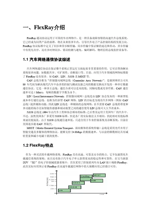
1.2 FlexRay特点FlexRay提供了传统车内通信协议不具备的大量特性,包括:(1)高传输速率:FlexRay的每个信道具有10Mbps带宽。
由于它不仅可以像CAN和LIN网络这样的单信道系统一般运行,而且还可以作为一个双信道系统运行,因此可以达到20Mbps的最大传输速率,是当前CAN最高运行速率的20倍。
flexray协议详解FlexRay协议是一种用于汽车网络通讯的实时通讯协议,旨在满足现代汽车对复杂实时通讯系统的需求。
FlexRay协议具有高带宽、实时性强和容错性好等特点,适用于汽车电子系统中需要高性能实时通讯的场景。
首先,让我们来看一下FlexRay协议的基本特点。
FlexRay采用了双信道、时间分割多路访问技术,可以支持不同的通讯速率,通常为10Mbps或者更高。
它还采用了静态和动态分段的方法,以支持不同类型的通讯数据。
此外,FlexRay协议还具有灵活的时隙和帧结构,能够满足复杂汽车电子系统对实时性和带宽的需求。
其次,FlexRay协议的通讯结构也是其重要特点之一。
FlexRay 网络由两个通道组成,分别为A通道和B通道,这种双通道结构可以提高系统的可靠性和容错性。
此外,FlexRay还采用了静态分段和动态分段的方式,可以支持不同类型的通讯数据,如周期性数据和事件触发数据。
这种通讯结构使得FlexRay协议非常适合于汽车电子系统中对实时性要求较高的场景。
此外,FlexRay协议还具有灵活的帧结构。
FlexRay帧由静态段和动态段组成,静态段用于周期性数据的传输,而动态段用于事件触发数据的传输。
这种帧结构可以满足不同类型数据的传输需求,使得FlexRay协议非常适合于汽车电子系统中复杂的通讯场景。
最后,FlexRay协议还具有丰富的错误检测和容错机制。
FlexRay网络支持节点之间的时钟同步,以确保数据的实时性和准确性。
此外,FlexRay还支持节点冗余和信道冗余,以提高系统的容错能力。
这些特点使得FlexRay协议在汽车电子系统中具有较高的可靠性和稳定性。
总的来说,FlexRay协议是一种适用于汽车电子系统的高性能实时通讯协议,具有高带宽、实时性强和容错性好等特点,适用于复杂的汽车电子系统中对实时通讯的需求。
通过灵活的通讯结构和丰富的错误检测和容错机制,FlexRay协议能够满足现代汽车对复杂实时通讯系统的需求,为汽车电子系统的发展提供了重要的技术支持。
Chapter 1IntroductionFlexRay通信协议1.1ScopeThe FlexRay communication protocol described in this document is specified for a dependable automotive network. Some of the basic characteristics of the FlexRay protocol are synchronous and asynchronous frame transfer, guaranteed frame latency and jitter during synchronous transfer, prioritization of frames during asynchronous transfer, multi-master clock synchronization1, error detection and signaling, error containment on the physical layer through the use of a bus guardian device, and scalable fault tolerance2.1.2References1.2.1FlexRay consortium documents[EPL05]FlexRay Communications System - Electrical Physical Layer Specification, v2.1 Revision A, FlexRay Consortium, December 2005.[EPLAN05]FlexRay Communications System - Electrical Physical Layer Application Notes, v2.1 Revision A, FlexRay Consortium, December 2005.[DLLCT05]FlexRay Communications System - Data Link Layer Conformance Test Specification, v1.0, FlexRay Consortium, December 2005.[Req05]FlexRay Requirements Specification, v2.100, FlexRay Consortium, December 2005.[Mül01] B. Müller, “On FlexRay Clock Synchronisation”, Robert Bosch Corporation, 2001 (internal document).[Ung02]J. Ungermann, “Performance of the FlexRay Clock Synchronisation”, Philips GmbH, 2002 (internal document).1.2.2Non-consortium documents[Cas93]G. Castagnoli, S. Bräuer, and M. Herrmann, "Optimization of Cyclic Redundancy-Check Codes with 24 and 32 Parity Bits", IEEE Transactions on Communications, vol. 41, pp. 883-892, June1993.[Koo02]P. Koopman, "32-bit Cyclic Redundancy Codes for Internet Applications", Proceedings of the International Conference on Dependable Systems and Networks (DSN 2002), Washington DC,pp. 459-468. June 2002.[Pet72]W. W. Peterson and E. J. Weldon, Jr., Error-Correcting Codes, 2nd ed., Cambridge MA: M.I.T.Press, 1972.[Rau02]M. Rausch, "Optimierte Mechanismen und Algorithmen in FlexRay", Elektronik Automotive, pp.36-40, December 2002.1 Multi-master clock synchronization refers to a synchronization that is based on the clocks of several (three or more)synchronization masters or sync nodes.2 Scalable fault tolerance refers to the ability of the FlexRay protocol to operate in configurations that provide various degrees offault tolerance (for example, single or dual channel clusters, clusters with or without bus guardians, clusters with many or few sync nodes, etc.).[Wad01]T. Wadayama, “Average Distortion of Some Cyclic Codes”, web site available at: http://www-tkm.ics.nitech.ac.jp/~wadayama/distortion.html[Wel88]J. L. Welch and N. A. Lynch, "A New Fault-Tolerant Algorithm for Clock Synchronization", Infor-mation and Computation, vol. 77, no. 1, pp. 1-36, April 1988.[Z100]ITU-T Recommendation Z.100 (03/93), Programming Languages - CCITT Specification and Description Language (SDL), International Telecommunication Union, Geneva, 1993.1.3Revision history Vers.Date Changes2.030-Jun-2004First public release.2.1May2005The SDL processes in Chapter 3 (Coding) have been restructured.Appendix B has been almost completely rewritten.BG references and BGSM chapter (former chapter 10) have been removed. Specific significant changes to CHI:•channel dependency of pMicroInitialOffset[Ch] and pMacroInitialOffset[CH] has been introduced in 9.3.1.1.2•pDecodingCorrection has been added in CHI in 9.3.1.1.2•error indicator in CHI has been added in 9.3.1.3.3•vSyncFramesEven/Odd/A/B have been removed in 9.3.1.3.4•indicators for zLastDynTxSlot have been added in 9.3.1.3.9The status variable vPOC!StartupState has been introduced in the CHI in 9.3.1.3.1. The variable is reset in Figure 2-6 to Figure 2-8 and set in Figure 7-11 to Figure 7-19.Figure 6-10 was split into two figures (now Figure 6-10 and Figure 6-11).The following figures have modifications that changed the operation of the protocol: Figure 2-8, Figure 5-21, Figure 6-8, Figure 6-16 (former 6-15), Figure 6-17 (former 6-16), Figure 7-3, Figure 7-11, Figure 7-19, Figure 8-4, Figure 8-8, Figure 8-10, Fig-ure 8-11, Figure 8-15, and Figure 8-17. The text related to these figures has also been updated.Numerous non-technical corrections and clarifications were made throughout the document.2.1 Rev A Dec2005Use of SDL priority input to resolve certain race conditions (see section 1.7.3.4 andFigure 5-21 and Figure 8-8)Re-arrangement of SDL to eliminate the use of SDL "enabling condition" structure(Figure 6-10, Figure 6-11, Figure 7-3, Figure 7-4, and Figure 7-5)Update of zLastDynTxSlot (Figure 5-13, Figure 5-20, Figure 5-21, and Figure 5-22)Re-arrangement of channel idle detection (Figure 2-9, Figure 3-15, Figure 3-16, Fig-ure 3-17, Figure 3-18, Figure 3-25, Figure 3-36, Figure 3-37, Figure 7-3, and Figure7-11)Introduction of new "a" class of variables (see section 1.6.1)Replacement of the bit counter by a timer in Figure 3-23Explicit export of all CHI variablesExtension of the color coding to SDL signals (see section 1.6.2)Rework of Appendix BNumerous non-technical corrections and clarifications were made throughout thedocument.Table 1-1: Revision history1.4Terms and definitionsapplication datadata produced and/or used by application tasks. In the automotive context the term 'signal' is often used for application data exchanged among tasks.busa communication system topology in which nodes are directly connected to a single, commoncommunication media (as opposed to connection through stars, gateways, etc.). The term bus is also used to refer to the media itself.bus driveran electronic component consisting of a transmitter and a receiver that connects a communication controller to one communication channel.bus guardianan electronic component that protects a channel from interference caused by communication that is not temporally aligned with the cluster's communication schedule by limiting the times that acommunication controller can transmit to those times allowed by the schedule.channelsee communication channel.channel idlethe condition of medium idle as perceived by each individual node in the network.cliqueset of communication controllers having the same view of certain systems properties, e.g., the global time value or the activity state of communication controllers.clustera communication system of multiple nodes connected via at least one communication channel directly(bus topology) or by star couplers (star topology).coldstart nodea node capable of initiating the communication startup procedure on the cluster by sending startupframes.communication channelthe inter-node connection through which signals are conveyed for the purpose of communication. The communication channel abstracts both the network topology, i.e., bus or star, as well as the physical transmission medium, i.e. electrical or optical.communication controller (CC)an electronic component in a node that is responsible for implementing the protocol aspects of the FlexRay communications system.communication cycleone complete instance of the communication structure that is periodically repeated to comprise the media access method of the FlexRay system. The communication cycle consists of a static segment, an optional dynamic segment, an optional symbol window, and a network idle time.communication slotan interval of time during which access to a communication channel is granted exclusively to a specific node for the transmission of a frame with a frame ID corresponding to the slot. FlexRay distinguishes between static communication slots and dynamic communication slots.cycle counterthe number of the current communication cycle.cycle timethe time within the current communication cycle, expressed in units of macroticks. Cycle time is reset to zero at the beginning of each communication cycle.dynamic segmentportion of the communication cycle where the media access is controlled via a mini-slotting scheme, also known as Flexible Time Division Multiple Access (FTDMA). During this segment access to the media is dynamically granted on a priority basis to nodes with data to transmit.dynamic communication slotan interval of time within the dynamic segment of the communication cycle consisting of one or more minislots during which access to a communication channel is granted exclusively to a specific node for transmission of a frame with a frame ID corresponding to the slot. In contrast to a static communication slot, the duration of a dynamic communication slot may vary depending on the length of the frame. If no frame is sent, the duration of a dynamic communication slot equals that of one minislot.framea structure used by the communication system to exchange information within the system. A frameconsists of a header segment, a payload segment and a trailer segment. The payload segment is used to convey application data.frame identifierthe frame identifier defines the slot position in the static segment and defines the priority in thedynamic segment. A lower identifier indicates a higher priority.gatewaya node that is connected to two or more independent communication networks that allows informationto flow between the networks.global timecombination of cycle counter and cycle time.Hamming distancethe minimum distance (i.e., the number of bits which differ) between any two valid code words in a binary code.the part of an ECU where the application software is executed, separated by the CHI from the FlexRay protocol engine.macrotickan interval of time derived from the cluster-wide clock synchronization algorithm. A macrotick consists of an integral number of microticks. The actual number of microticks in a given macrotick is adjusted by the clock synchronization algorithm. The macrotick represents the smallest granularity unit of the global time.medium idlethe condition of the physical transmission medium when no node is actively transmitting on thephysical transmission medium.microtickan interval of time derived directly from the CC's oscillator (possibly through the use of a prescaler).The microtick is not affected by the clock synchronization mechanisms, and is thus a node-local concept. Different nodes can have microticks of different duration.minislotan interval of time within the dynamic segment of the communication cycle that is of constant duration (in terms of macroticks) and that is used by the synchronized FTDMA media access scheme to manage media arbitration.networkthe combination of the communication channels that connect the nodes of a cluster.network topologythe arrangement of the connections between the nodes. FlexRay supports bus, star, cascaded star, and hybrid network topologies.nodea logical entity connected to the network that is capable of sending and/or receiving frames.null framea frame that contains no usable data in the payload segment. A null frame is indicated by a bit in theheader segment, and all data bytes in the payload segment are set to zero.physical communication linkan inter-node connection through which signals are conveyed for the purpose of communication. All nodes connected to a given physical communication link share the same electrical or optical signals(i.e., they are not connected through repeaters, stars, gateways, etc.). Examples of a physicalcommunication link include a bus network or a point-to-point connection between a node and a star. A communication channel may be constructed by combining one or more physical communication links together using stars.precisionthe worst-case deviation between the corresponding macroticks of any two synchronized nodes in the cluster.see communication slot.stara device that allows information to be transferred from one physical communication link to one or moreother physical communication links. A star duplicates information present on one of its links to the other links connected to the star. A star can be either passive or active.startup frameFlexRay frame whose header segment contains an indicator that integrating nodes may use time-related information from this frame for initialization during the startup process. Startup frames are always also sync frames.startup slotcommunication slot in which a startup frame is sent.static communication slotan interval of time within the static segment of the communication cycle that is constant in terms of macroticks and during which access to a communication channel is granted exclusively to a specific node for transmission of a frame with a frame ID corresponding to the slot. Unlike a dynamiccommunication slot, each static communication slot contains a constant number of macroticksregardless of whether or not a frame is sent in the slot.static segmentportion of the communication cycle where the media access is controlled via a static Time Division Multiple Access (TDMA) scheme. During this segment access to the media is determined solely by the progression of time.sync frameFlexRay frame whose header segment contains an indicator that the deviation measured between the frame's arrival time and its expected arrival time should be used by the clock synchronizationalgorithm.sync slotcommunication slot in which a sync frame is sent.1.5Acronyms and abbreviationsµT MicrotickAP Action PointBD Bus DriverBIST Built-In Self TestBITSTRB Bit Strobing ProcessBSS Byte Start SequenceCAS Collision Avoidance SymbolCC Communication ControllerCE Communication ElementCHI Controller Host InterfaceCHIRP Channel Idle Recognition PointCODEC Coding and Decoding ProcessCRC Cyclic Redundancy CodeCSP Clock Synchronization ProcessCSS Clock Synchronization Startup ProcessDTS Dynamic Trailing SequenceECU Electronic Control Unit, same as nodeEMC Electromagnetic CompatibilityERRN Error Not signalFES Frame End SequenceFSP Frame and Symbol ProcessingFSS Frame Start SequenceFTDMA Flexible Time Division Multiple Access (media access method) FTM Fault Tolerant MidpointID IdentifierINH Inhibit signalMAC Media Access Control ProcessMT MacrotickMTG Macrotick Generation ProcessMTS Media Access Test SymbolNIT Network Idle TimeNM Network ManagementPOC Protocol Operation ControlRxD Receive data signal from bus driverRxEN Receive data enable signal from bus driverSDL Specification and Description LanguageSPI Serial Peripheral InterfaceSTBN Standby Not signalSuF Startup FrameSW Symbol WindowSyF Sync FrameTDMA Time Division Multiple Access (media access method)TRP Time Reference PointTSS Transmission Start SequenceTxDTransmit Data signal from CC TxENTransmit Data Enable Not signal from CC WUPWakeup Pattern WUSWakeup Symbol WUPDEC Wakeup Pattern Decoding Process 1.6Notational conventions 1.6.1Parameter prefix conventions<variable> ::= <prefix_1> [<prefix_2>] Name<prefix_1>::= a | c | v | g | p | z<prefix_2>::= d | s1.6.2Color codingThroughout the text several types of items are highlighted through the use of an italicized color font.NamingConventionInformation Type Description aAuxiliary Parameter Auxiliary parameter used in the definition or derivation of other parameters or in the derivation of constraints.cProtocol Constant Values used to define characteristics or limits of the protocol. These values are fixed for the protocol and cannot be changed.vNode Variable Values that vary depending on time, events, etc.g ClusterParameterParameter that must have the same value in all nodes in a cluster, is initialized in the POC:default config state, and can only be changed while in the POC:config state.p Node Para-meterParameter that may have different values in different nodes in the cluster, is initialized in the POC:default config state, and can only be changed while in the POC:config state.zLocal SDLProcessVariable Variables used in SDL processes to facilitate accurate representa-tion of the necessary algorithmic behavior. Their scope is local to the process where they are declared and their existence in any particu-lar implementation is not mandated by the protocol.Table 1-2: Parameter prefix 1.NamingConventionInformation Type Description dTime Duration Value (variable, parameter, etc.) describing a time duration, the time between two points in time s Set Set of values (variables, parameters, etc.)Table 1-3: Parameter prefix 2.Parameters, constants and variables are highlighted with blue italics. An example is the parameter gdStat-icSlot. This convention is not used within SDL diagrams, as it is assumed that such information is obvious. The meaning of the prefixes of parameters, constants, and variables is described in section 1.6.1.SDL states are highlighted in green italics. An example is the SDL state POC:normal active. This highlighting convention is not used within SDL diagrams. Further notational conventions related to SDL states are described in section 1.7.2.SDL signals are highlighted in brown italics. An example is the SDL signal CHIRP on A. Again, this convention is not used within the SDL diagrams themselves as the fact that an item is an input or output signal should be obvious.Terms which are important for FlexRay are highlighted in red italics at their first (or defining) instance in the text. An example is the term communication element.1.7SDL conventions1.7.1GeneralThe FlexRay protocol mechanisms described in this specification are presented using a graphical method loosely based on the Specification and Description Language (SDL) technique described in [Z100]. The intent of this description is not to provide a complete executable SDL model of the protocol mechanisms, but rather to present a reasonably unambiguous description of the mechanisms and their interactions. This description is intended to be read by humans, not by machines, and in many cases the description is optimized for understandability rather than exact syntactic correctness.The SDL descriptions in this specification are behavioral descriptions, not requirements on a particular method of implementation. In many cases the method of description was chosen for ease of understanding rather than efficiency of implementation. An actual implementation should have the same behavior as the SDL description, but it need not have the same underlying structure or mechanisms.Several SDL diagrams have textual descriptions intended to assist the reader in understanding the behavior depicted in the SDL diagrams. Some technical details are intentionally omitted from these explanations. Unless specifically mentioned, the behavior depicted in the SDL diagrams takes precedence over any textual description.The SDL in this specification describes a dual channel FlexRay device. As a result, there are a number of mechanisms that exhibit behavior that is specific to a given channel. It is also possible to have FlexRay devices that only support a single channel, or that may be configured to support a single channel. Imple-menters of single channel devices will have to make appropriate adjustments to eliminate the effects of mechanisms and signals that do not exist in devices operating in a single channel mode.1.7.2SDL Notational ConventionsStates that exist within the various SDL processes are shown with the state symbol shaded in light gray. These states are named with all lowercase letters. Acronyms or proper nouns that appear in a state name are capitalized as appropriate. Examples include the states "wait for sync frame" and "wait for CE start". SDL states that are referenced in the text are prefixed with an identification of the SDL process in which they are located (for example, the state POC:normal active refers to the "normal active" state in the POC process). This convention is not used within the SDL diagrams themselves, as the process information should be obvious.The definitions of an SDL process are often spread over several different figures. The caption of each figure that contains SDL definitions indicates to which SDL process the figure belongs.1.7.3SDL ExtensionsThe SDL descriptions in this specification contain some constructs that are not a part of normal SDL. Also, some mechanisms described with constructs that are part of normal SDL expect that these constructs behave somewhat differently than is described in [Z100]. This section documents significant deviations from "standard" SDL.1.7.3.1Microtick, macrotick and sample tick timersThe representation of time in the FlexRay protocol is based on a hierarchy that includes microticks and macroticks (see Chapter 8 for details). Several SDL mechanisms need timers that measure a certain number of microticks or macroticks. This specification makes use of an extension of the SDL 'timer' construct to accomplish this.An SDL definition of the formµT timerdefines a timer that counts in terms of microticks. This behavior would be similar to that of an SDL system whose underlying time unit is the microtick.An SDL definition of the formMT timerdefines a timer that counts in terms of macroticks. Note that a macrotick timer uses the corrected macroticks generated by the macrotick generation process. Since the duration of a macrotick can vary, the duration of these timers can also vary, but the timers themselves remain synchronized to the macrotick-level timebase of the protocol.In all other respects both of these constructs behave in the same manner as normal SDL timers.In addition to the above, several SDL mechanisms used in the description of encoding make use of a timer that measures a certain number of ticks of the bit sample clock. An SDL definition of the form ST timerdefines a timer that counts in terms of ticks of the bit sample clock (i.e., sample ticks). This behavior would be similar to that of an SDL system whose underlying time unit is the sample tick. In all other respects this construct behaves in the same manner as a normal SDL timer.There is a defined relationship between the "ticks" of the microtick timebase and the sample ticks of bit sampling. Specifically, a microtick consists of an integral number, pSamplesPerMicrotick, of sample ticks. As a result, there is a fixed phase relationship between the microtick timebase and the ticks of the sample clock.The time expression of a timer is defined in [Z100] by:<Time expression> = now + <Duration constant expression>In this specification the time expression is used in the following simplified way:<Time expression> = <Duration constant expression>31.7.3.2Microtick behavior of the 'now' - expressionThe behavioral descriptions of various aspects of the FlexRay system require the ability to take "time-stamps" at the occurrence of certain events. The granularity of these timestamps is one microtick, and the timestamps taken by different processes need to be taken against the same underlying timebase. This specification makes use of an extension of the SDL concept of time to facilitate these timestamps.3 If the duration time expression is zero or negative then the timer is started and expires immediately.This specification assumes the existence of an underlying microtick timebase. This timebase, which is available to all processes, contains a microtick counter that is started at zero at some arbitrary epoch assumed to occur before system startup. As time progresses, this timebase increments the microtick counter without bound4. Explicit use of the SDL 'now' construct returns the value of this microtick counter. The difference between the timestamps of two events represents the number of microticks that have occurred between the events.1.7.3.3Channel-specific process replicationThe FlexRay protocol described in this specification is a dual channel protocol. Several of the mechanisms in the protocol are replicated on a channel basis, i.e., essentially identical mechanisms are executed, one for channel A and one for channel B. This specification only provides SDL descriptions for the channel-specific processes on channel A - it is assumed that whenever a channel-specific process is defined for channel A there is another, essentially identical, process defined for channel B, even though this process is not explicitly described in the specification.Channel-specific processes have names that include the identity of their channel (for example, "Clock synchronization startup process on channel A [CSS_A]"). In addition, signals that leave a channel-specific process have signal names that include the identity of their channel (for example, the signal integration aborted on A).1.7.3.4Handling of Priority Input SymbolsThe SDL language contains certain ambiguities regarding the order of execution of processes if multiple processes have input queues that are not empty. For example, the usage of timers and clock oscillator inputs causes multiple processes to be eligible for execution at the beginning of clock edges. Generally, this poses no problem for the FlexRay specification, but for certain special cases it is not possible to specify the required behavior in an unambiguous way without additional language constructs.To resolve these situations the SDL priority input symbol is used, but with a slightly extended meaning. Whenever an input priority symbol is used, no other exit path of this state may be taken unless it is impossible that the priority input could be triggered on the current microtick clock edge. Effectively, the execution of the process in question is stalled until all other process have executed. Should multiple processes be in a state where they are sensitive to a priority input, all are executed last and in random order. The message queue is handled in the standard way, i.e. the signal triggering the priority input is removed from the queue while any signals placed before or after are preserved for the succeeding state.1.8Network topology considerationsThe following sections provide a brief overview of the possible topologies for a FlexRay system. This material is for reference only - detailed requirements and specifications may be found in [EPL05].There are several ways to design a FlexRay cluster. It can be configured as a single-channel or dual-channel bus network, a single-channel or dual-channel star network, or in various hybrid combinations of bus and star topologies.A FlexRay cluster consists of at most two channels, identified as Channel A and Channel B. Each node in the cluster may be connected to either or both of the channels. In the fault free condition, all nodes connected to Channel A are able to communicate with all other nodes connected to Channel A, and all nodes connected to ChannelB are able to communicate with all other nodes connected to Channel B. If a node needs to be connected to more than one cluster then the connection to each cluster must be made through a different communication controller5.4 This is in contrast to the vMicrotick variable, which is reset to zero at the beginning of each cycle.5 For example, it is not allowed for a communication controller to connect to Channel A of one cluster and Channel B of anothercluster.。
通信协议标准FlexRay总线的功能安全性详解在汽车中采用电子系统已经有几十年的历史,它们使汽车安全、节能与环保方面的性能有大幅度的提高。
随着研究的深入,许多系统需要共享和交换信息,为了节省线缆,就形成了依赖于通信的分布式嵌入系统。
目前,世界上90%的都采用基于CAN总线的系统。
FlexRay是下一代通信协议事实上的标准,它的功能安全性如何是至关重要的。
1 IEC61508功能安全的要求目前车控系统正在向线控技术(xbywire)过渡,例如线控转向与线控刹车。
线控系统最终目标是取消机械后备,因为取消这些后备可以降低成本,增强设计的灵活性,扩大适用范围,为以后新添功能创造条件。
但是取消机械后备就对电子系统的可信赖性(dependability)要求大为提高。
车是一个运动的物体,处于运动的环境之中,它因故障可能伤及自身及别人。
取消机械后备,就将电子系统由今天的故障静默(failsilent)要求提升到故障仍工作(failoperational)的要求。
国际上对工业应用的功能安全要求已制定了标准IEC61508,它主要关心被控设备及其控制系统的安全。
虽然它也适用于汽车,但汽车不仅有上述功能安全问题,而且要关心由于功能变化造成的整车系统安全,所以汽车业内正在制定相应的标准ISO26262。
汽车的功能安全等级分为4级,要求最高的是 ASILD,相应的失效概率<10-8/h,它相当于IEC61508的SIL3。
根据实践经验,分配给通信的失效概率<10-10/h。
有关这方面的介绍可参见参考文献。
现在安全攸关的应用系统的范围有所扩大,以前不算在内的一些系统现在都要算了。
例如安全预先动作系统(presafe)中座椅调整子系统、刹车辅助系统中的灯光控制子系统、碰撞后telematic自动呼叫求援的子系统,都将视为安全攸关系统。
1.1 引起系统安全风险的通信故障通信故障有5种表现形式,第1种是造成值域的错误。
第2种是造成时域的错误,这是工业不同于民用的部分。
FlexRay通信系统协议规范V2.1修订本A-第⼋章时钟同步Chapter 8Clock Synchronization8.1IntroductionIn a distributed communication system every node has its own clock. Because of temperature fluctuations, voltage fluctuations, and production tolerances of the timing source (an oscillator, for example), the internal time bases of the various nodes diverge after a short time, even if all the internal time bases are initially synchronized.Figure 8-1: Clock synchronization context.A basic assumption for a time-triggered system is that every node in the cluster has approximately the same view of time and this common global view of time is used as the basis for the communication timing for each node. In this context, "approximately the same" means that the difference between any two nodes' views of the global time is within a specified tolerance limit. The maximum value of this difference is known as the precision.The FlexRay protocol uses a distributed clock synchronization mechanism in which each node individually synchronizes itself to the cluster by observing the timing of transmitted sync frames from other nodes. A fault-tolerant algorithm is used.The macroticks are synchronized on a cluster-wide basis. Within tolerances, the duration of a macrotick is identical throughout all synchronized nodes in a cluster. The duration of each local macrotick is an integer number of microticks; the number of microticks per macrotick may, however, differ from macrotick to macrotick within the same node. The number of microticks per macrotick may also differ between nodes, and depends on the oscillator frequency and the prescaler. Although any given macrotick consists of an integral number of microticks, the average duration of all macroticks in a given cycle may be non-integral(i.e., it may consist of a whole number of microticks plus a fraction of a microtick).9089 The dark lines represent data flows between mechanisms that are relevant to this chapter. The lighter gray lines are relevantto the protocol, but not to this chapter.A cycle consists of an integer number of macroticks. The number of macroticks per cycle shall be identical in all nodes in a cluster, and remains the same from cycle to cycle. At any given time all nodes should have the same cycle number (except at cycle boundaries as a result of imperfect synchronization in the cluster).91 8.2.2Global and local timeThe global time of a cluster is the general common understanding of time inside the cluster. The FlexRay protocol does not have an absolute or reference global time; every node has its own local view of the global time.The local time is the time of the node's clock and is represented by the variables vCycleCounter, vMacrotick, and vMicrotick. vCycleCounter and vMacrotick shall be visible to the application. The update of vCycleCounter at the beginning of a cycle shall be atomic with the update of vMacrotick.92The local time is based on the local view of the global time. Every node uses the clock synchronization algorithm to attempt to adapt its local view of time to the global time.The precision of a cluster is the maximum difference between the local times of any two synchronized nodes in the cluster. 8.2.3Parameters and variablesvCycleCounter is the (controller-local) cycle number and is incremented by one at the beginning of each communication cycle. vCycleCounter ranges from 0 to cCycleCountMax. When cCycleCountMax is reached, the cycle countervCycleCounter shall be reset to zero in the next communication cycle instead of being incremented.vMacrotick represents the current value of the (controller-local) macrotick and ranges from 0 to (gMacro-PerCycle - 1). gMacroPerCycle defines the (integer) number of macroticks per cycle.vMicrotick represents the current value of the (controller-local) microtick.syntypeT_Macrotick = Integerendsyntype;syntypeT_Microtick = Integerendsyntype;Definition 8-1: Formal definition of T_Macrotick and T_Microtick.The FlexRay "timing" will be configured by:gMacroPerCycle andtwo of the three parameters pMicroPerCycle, gdCycle and pdMicrotick. pMicroPerCycle is the node specific number of microticks per cycle, gdCycle is the cluster wide duration of one communication cycle, and pdMicrotick is the node specific duration of one microtick. The relation between these three parameters is:pMicroPerCycle = round(gdCycle / pdMicrotick)90 This is true even for the nominal (uncorrected) average duration of a macrotick (for example 6000 microticks distributed over137 macroticks).91 The cycle number discrepancy is at most one, and lasts no longer than the precision of the system.92 An atomic action is an action where no interruption is possible.8.3Synchronization processClock synchronization consists of two main concurrent processes. The macrotick generation process (MTG) controls the cycle and macrotick counters and applies the rate and offset correction values. This process is explained in detail in section 8.7. The clock synchronization process (CSP) performs the initialization atcorrection. FlexRay uses a combination of both methods. The following conditions must be fulfilled:?Rate correction and offset correction shall be done in the same way in all nodes. Rate correction shall be performed over the entire cycle.Offset correction shall be performed only during the NIT in the odd communication cycle, starts at gOffsetCorrectionStart, and must be finished before the start of the next communication cycle.Offset changes (implemented by synchronizing the start time of the cycle) are described by the variable vOffsetCorrection. vOffsetCorrection indicates the number of microticks that are added to the offset correction segment of the network idle time. vOffsetCorrection may be negative. The value of vOffsetCorrection is determined by the clock synchronization algorithm. The calculation of vOffsetCorrection takes place every cycle but a correction is only applied at the end of odd commu-nication cycles. The calculation of vOffsetCorrection is based on values measured in a singlecommunication cycle. Although the SDL indicates that this computation cannot begin before the NIT, an implementation may start the computation of this parameter within the dynamic segment or symbol window as long as the reaction to the computation (update of the CHI and transmission of the SyncCalcResult and offset calc ready signals) is delayed until the NIT. The calculation must be complete before the offset correction phase begins.Rate (frequency) changes are described by the variable vRateCorrection. vRateCorrection is an integer number of microticks that are added to the configured number of microticks in a communica-tion cycle (pMicroPerCycle)93. vRateCorrection may be negative. The value of vRateCorrection is determined by the clock synchronization algorithm and is only computed once per double cycle. The calculation of vRateCorrection takes place following the static segment in an odd cycle. The calcula-tion of vRateCorrection is based on the values measured in an even-odd double cycle. Although the SDL indicates that this computation cannot begin before the NIT, an implementation may start the computation of this parameter within the dynamic segment or symbol window as long as the reaction to the computation (update of the CHI and transmission of the SyncCalcResult and rate calc ready signals) is delayed until the NIT. The calculation must be completed before the next even cycle begins.The following data types will be used in the definition of the clock synchronization process:newtype T_EvenOddliterals even, odd;endnewtype;syntypeT_Deviation = T_Microtickendsyntype;Definition 8-2: Formal definition of T_EvenOdd and T_Deviation.The protocol operation control (POC) process sets the operating mode for the clock synchronization process (CSP) (Figure 8-4) into one of the following modes:1.In the STANDBY mode the clock synchronization process is effectively halted.2.In the NOSYNC mode CSP performs clock synchronization under the assumption that it is not trans-mitting sync frames (i.e., it does not include its own clock in the clock correction computations).3.In the SYNC mode CSP performs clock synchronization under the assumption that it is transmittingsync frames (i.e., it includes its own clock in the clock correction computations).Definition 8-3 gives the formal definition of the CSP operating modes.newtype T_CspModeliterals STANDBY, NOSYNC, SYNC;endnewtype;newtype T_SyncCalcResultliterals WITHIN_BOUNDS, EXCEEDS_BOUNDS, MISSING_TERM;endnewtype;Definition 8-3: Formal definition of T_CspMode and T_SyncCalcResult.After the POC sets the CSP mode to something other than STANDBY, the CSP waits in the CSP:wait for startup state until the POC forces the node to a cold start or to integrate into a cluster. The startup procedure, including its initialization and interaction with other processes, is described in the macro INTEGRATION CONTROL, which is explained in section 8.4.Before further explanation of the processes an array is defined (Definition 8-4) which is used to store the frame IDs of the received sync frames.93 pMicroPerCycle is the configured number of microticks per communication cycle without correction.syntype T_ArrayIndex = Integerconstants 1 : 15endsyntype;syntype T_SyncNodes = Integerconstants 0 : cSyncNodeMaxendsyntype;newtype T_FrameIDTableArray(T_ArrayIndex, T_FrameID)endnewtype;Definition 8-4: Formal definition of T_ArrayIndex, T_SyncNodes, and T_FrameIDTable.Figure 8-4: Clock synchronization process overview [CSP].After finishing the startup procedure a repetitive sequence consisting of cycle initialization (Figure 8-10), a measurement phase (Figure 8-11), and offset (Figure 8-14) and rate (Figure 8-15) calculation is executed. All elements of this sequence are described below. The offset calculation will be done every cycle, the rate calculation only in the odd cycles.The clock synchronization control (Figure 8-5) handles mode changes done by the POC. It also handles process termination requests sent by the POC.Figure 8-5: Clock synchronization control [CSP].8.4Startup of the clockThe startup of the node's internal synchronized clock requiresthe initialization and start of the MTG process andthe initialization and start of the CSP process. This process contains the repetitive tasks of measurement and storage of deviation values and the calculation of the offset and the rate correction values.There are two ways to start the (synchronized) clock inside a node:The node is the leading coldstart node.The node adopts the initialization values (cycle counter, clock rate, and cycle start time) of a running coldstart node.Figure 8-6: Integration control [CSP].The startup procedure will be entered when the CSP receives the signal attempt integration from the POC (see Figure 8-4). The control of the node's startup is described in the INTEGRATION CONTROL macro depicted in Figure 8-6.8.4.1Cold start startupIf no ongoing communication on the channels is detected the POC may force the node to perform the role of the leading coldstart node of the cluster. This causes the following actions:The clock synchronization startup processes on channel A and B (CSS_A, CSS_B) will be termi-nated.The INTEGRATION CONTROL macro will be left.The macrotick generation process (MTG) (Figure 8-17) leaves the MTG:wait for start state.Depending on the initialization values, macrotick and cycle start signals are generated and distrib-uted to other processes. The CSP waits for the cycle start.The CSP and MTG processes continue their schedules until the POC changes the CSP mode to STANDBY or an error is detected.8.4.2Integration startupIf ongoing communication is detected during startup, or if the node is not allowed to perform a coldstart, the node attempts to integrate into the timing of the cluster by adopting the rate, the cycle number, and cycle start instant of a coldstart node. To accomplish this, the CSP process (Figure 8-6) instantiates the clock synchronization startup processes for channel A and B (CSS_A, CSS_B).After their instantiation, the CSS_A process (Figure 8-8) and the CSS_B process wait for a signal from the coding/decoding unit that a potential frame start was detected. The CSS process then takes a timestamp and waits for a signal indicating that a valid even startup frame was received. If no valid even startup frame was received the time stamp will be overwritten with the time stamp of the next potential frame start that is received.When a valid even startup frame is received the node is able to pre-calculate the initial values for the cycle counter and the macrotick counter. The node then waits for the corresponding odd startup frame. This frame is expected in a time window. When a potential frame start is detected in this time window the tMicroInitial-Offset timer is started in the INTEGRATION CONTROL macro. When this timer expires the MTG process (Figure 8-17) is started using the pre-calculated initial values. A second potential frame start inside the time window leads to a restart of the tMicroInitialOffset timer. Only one channel can start the MTG process (the initial channel).94 Between the expiration of the timer tMicroInitialOffset and the reception of the complete startup frame, the other channel (the non-initial channel) can not start, stop, or change the MTG process, but it can receive potential frame start events and can start its own tMicroInitialOffset timer. The behavior of the CSS process of the non-initial channel is the same as the behavior of the CSS process of the initial channel except that the non-initial channel is unable to start the MTG process and is unable to terminate itself and the CSS process of the other channel.94 There is no configuration that selects the channel that starts the MTG process. The process is started by the first channel thatreceives a potential frame start in the expected time window after reception of a valid even startup frame on the same channel (refer to Figure 8-8).Figure 8-7: Clock synchronization startup control [CSS_A].Figure 8-8: Clock synchronization startup process on channel A [CSS_A]95.The reception of the corresponding valid odd startup frame and the satisfaction of the conditions for integration leads to the termination of the CSS process for this channel. Before termination a signal is sent indicating successful integration; this signal causes the INTEGRATION CONTROL macro of CSP to terminate the CSS process for the other channel (see Figure 8-6). This behavior of this termination is depicted in Figure 8-7.The timer tSecondFrame in Figure 8-8 is used to restart the clock synchronization startup process if the corresponding odd startup frame was not received after an appropriate period of time.The variable zID is used to prohibit attempts to integrate on a coldstart node if an integration attempt on this coldstart node failed in the previous cycle. The timer tID prevents this prohibition from applying for more than one double cycle.8.5Time measurementEvery node shall measure and store, by channel, the time differences (in microticks) between the expected and the observed arrival times of all sync frames received during the static segment. A data structure is introduced in section 8.5.1. This data structure is used in the explanation of the initialization (section 8.5.2) and the measurement, storage, and deviation calculation mechanisms (section 8.5.3).95 The priority input symbol on the state CSS_A:wait for second startup frame has been included to resolve the ambiguity thatarises if the timer tSecondFrame expires at the same time a valid odd startup frame on A signal is received.Figure 8-9: Data structure example used in the following explanations.8.5.1Data structureThe following data types are introduced to enable a compact description of mechanisms related to clock synchronization: newtype T_DevValidstructValue T_Deviation;Valid Boolean;Startup Boolean;endnewtype;Definition 8-5: Formal definition of T_DevValid.newtype T_ChannelDevArray(T_Channel, T_DevValid)endnewtype;newtype T_EOChDevArray(T_EvenOdd, T_ChannelDev)endnewtype;newtype T_DevTableArray(T_ArrayIndex, T_EOChDev)endnewtype;Definition 8-6: Formal definition of T_ChannelDev, T_EOChDev, and T_DevTable.The structured data type T_DevTable is a three dimensional array with the dimensions line number (1 …15), communication channel (A or B), and communication cycle (even or odd). Each line is used to store the received data of one sync node. If the node is itself a sync node the first line is used to store a deviation of zero, corresponding to the deviation of its own sync frame. Each element in this three dimensional array contains a deviation value (the structure element Value), a Boolean value indicating whether the deviation value is valid (the structure element Valid), and a Boolean value indicating whether the sync frame corre-sponding to this deviation was a startup frame (the structure element Startup). Figure 8-9 gives an example of this data structure.8.5.2InitializationThe data structure introduced in section 8.5.1 is used to instantiate a variable (zsDev). A portion of this variable will be reset at the beginning of every communication cycle; the even part at the beginning of an even cycle and the odd part at the beginning of an odd cycle. Additionally, if the node is configured to transmit sync frames (mode SYNC), corresponding entries are stored in the variable as depicted in Figure 8-10.Figure 8-10: Initialization of the data structure for measurement [CSP].8.5.3Time measurement storageThe expected arrival time of a frame is the static slot action point, which is defined in Chapter 5. The MAC generates a signal when the static slot action point is reached. When the clock synchronization process receives this action point signal a time stamp is taken and saved.During the reception of a frame the decoding unit takes a time stamp when the secondary time reference point is detected. This time stamp is based on the same microtick time base that is used for the static slot action point time stamp. The decoding unit then computes the primary time reference point by subtracting a configurable offset value from the secondary time reference point time stamp. This result is passed to the Frame and Symbol Processing process, which then passes the results to CSP for each valid sync frame received. Further information on the definition of the reference points may be found in section 3.2.5.Figure 8-11: Measurement and storage of the deviation values [CSP].The difference between the action point and primary time reference point time stamps, along with Booleans indicating that the data is valid and whether or not the frame is also a startup frame, is saved in the appro-priate location in the previously defined data structure (see Figure 8-11). The measurement phase ends when the static segment ends.The reception of more than gSyncNodeMax sync frames per channel in one communication cycle indicates an error inside the cluster. This is reported to the host and only the first gSyncNodeMax received sync frames are used for the correction value calculation.8.6Correction term calculation8.6.1Fault-tolerant midpoint algorithmThe technique used for the calculation of the correction terms is a fault-tolerant midpoint algorithm (FTM). The algorithm works as follows (see Figure 8-12 and Figure 8-13):1.The algorithm determines the value of a parameter, k, based on the number of values in the sorted list(see Table 8-1).96Number of values k1 - 203 - 71> 72Table 8-1: FTM term deletion as a function of list size.96 The parameter k is not the number of asymmetric faults that can be tolerated.97 The division by two of odd numbers should truncate toward zero such that the result is an integer number. Example: 17 / 2 =8 and -17 / 2 = -8.Figure 8-13: Fault Tolerant Midpoint Procedure.8.6.2Calculation of the offset correction valueThe offset correction value vOffsetCorrection is a signed integer that indicates how many microticks the node should shift the start of its cycle. Negative values mean the NIT should be shortened (making the next cycle start earlier). Positive values mean the NIT should be lengthened (making the next cycle start later).In Figure 8-14 the procedure of the calculation of the offset correction value is described in detail. The following steps are covered in the SDL diagram in Figure 8-14:1.Selection of the previously stored deviation values. Only deviation values that were measured andstored in the current communication cycle are used. If a given sync frame ID has two deviation values (one for channel A and one for channel B) the smaller value will be selected.2.The number of received sync frames is checked and if no sync frames were received an error flag isset to true.3.The fault-tolerant midpoint algorithm is executed (see section 8.6.1).4.The correction term is checked against specified limits. If the correction term is outside of the specifiedlimits an error flag is set to true and the correction term is set to the maximum or minimum value as appropriate (see section 8.6.4).5.If appropriate, an external correction value supplied by the host is added to the calculated and checkedcorrection term (see section 8.6.5).The following data structure is used to save and handle the selected data:newtype T_DeviationTableArray(T_ArrayIndex, T_Deviation)endnewtype;Definition 8-7: Formal definition of T_DeviationTable.Figure 8-14: Calculation of the offset correction value [CSP].The SDL abstraction of execution in zero time could lead the reader to the conclusion that the calculation of the offset correction value needs to complete in zero time. This is of course unachievable. It is anticipated that real implementationsmay take substantial time to calculate the correction, and that implementations may begin the calculation earlier than is shown in Figure 8-4 (i.e., may begin the calculation during the measurement process). Therefore the following restriction on the time required for offset correction calcu-lation is introduced:The offset correction calculation must be completed no later than cdMaxOffsetCalculation after the end of the static segment or 1 MT after the start of the NIT, whichever occurs later.8.6.3Calculation of the rate correction valueThe goal of the rate correction is to bring the rates of all nodes inside the cluster close together. The rate correction value is determined by comparing the corresponding measured time differences from two successive cycles. A detailed description is given by the SDL diagram depicted in Figure 8-15.。
竭诚为您提供优质文档/双击可除flexray总线协议篇一:FlexRay总线调研报告FlexRay总线调研报告汽车电子已成为汽车行业的一个重要市场。
汽车电子行业最大的热点就是网络化[1]。
如今的汽车,已然是一个移动式的信息装置,通过车内网络系统,可以接收、发送并处理大量的数据,对某些状况做出必要的反应。
未来汽车的发展趋势必然是自动化程度越来越高,使汽车更安全、更可靠、更舒适,这意味着在车内使用更多的传感器、传动装置及电子控制单元,这也将对车载网络提出更高的要求。
针对未来汽车车载网络的发展要求,FlexRay应运而生。
FlexRay关注的是当今汽车行业的一些核心需求,包括更快的数据速率,更灵活的数据通信,更全面的拓扑选择和容错运算等。
FlexRay的出现,弥补了既有总线协议应用在汽车线控系统或者同安全相关的系统时容错性和传输速率太低的不足,并将逐步取代can总线成为新一代的汽车总线[2]。
1FlexRay总线介绍1.1车载网络概述现代科技推动了汽车网络技术的不断发展,早在20世纪80年代国际上众多知名汽车公司就积极致力于汽车网络技术的研究及应用,迄今为止,已有多种网络标准。
1994年,sae车辆网络委员会将汽车数据传输网划分为a、b、c等3类。
a类为面向传感器∕执行器控制的低速网络,b类为面向数据共享的中速网络,c类为面向高速、实时闭环控制的多路传输网络[3]。
另外它还保留了d类网的定义,这类网络主要是面向车内的娱乐设备的信息传输。
四种汽车网络标准总结如表1所示。
表1汽车网络标准a类网络主要面向传感器、执行器控制,是低速网络。
在该类网络中对实时性要求不高,且不需要诊断功能,数据速率一般在1~10kbps,主要应用于电动门窗、座椅调节、灯光照明等控制。
目前a类网络协议主要有ttp/a(time-triggeredprotocol)、lin(localinterconnectnetwork)等协议。
b类网络主要面向独立模块间的数据共享,是中速网络,该类网络适用于对实时性要求不高的通信场合,数据速率一般在10~100kbps,主要应用于电子车辆信心中心、故障诊断、仪表显示、安全气囊等系统,以减少冗余的传感器和其他电子部件。
一、FlexRay介绍FlexRay通讯协议运用于可靠的车内网络中,是一种具备故障容错的高速汽车总线系统。
它已经成为同类产品的基准,将在未来很多年内,引导汽车电子产品控制结构的发展方向。
FlexRay协议标准中定义了同步和异步帧传输,同步传输中保证帧的延迟和抖动,异步传输中有优先次序,还有多时钟同步,错误检测与避免,编码解码,物理层的总线监控设备等。
1.1汽车网络通信协议综述汽车网络通信协议在保证整个系统正常运行方面起着非常重要的作用。
它可以帮助解决系统很多问题,如数据共享、可扩展性、诊断接口等。
目前,应用于汽车领域的网络标准除了FlexRay还有很多,如CAN、LIN、J1850及MOST等。
CAN总线全称为“控制器局域网总线(Controller Area Network)”,是德国博世公司从80年代初为解决现代汽车中众多的控制与测试仪器之间的数据交换而开发的一种串行数据通信协议。
它是一种多主总线,通信介质可以是双绞线、同轴电缆或光导纤维。
CAN通信速率可达1Mbit/s,每帧的数据字节数为8个。
LIN(Local Interconnect Network,控制器局域网)总线是由LIN 协会发布的一种新型低成本串行通信总线,也称为经济型CAN网络。
LIN的目标是为现有汽车网络(例如CAN 总线)提供辅助功能,因此LIN总线是一种辅助的总线网络,在不需要CAN 总线的带宽和多功能的场合比如智能传感器和制动装置之间的通信使用LIN总线可大大节省成本。
J1850总线是1994年由汽车工程师协会颁布的标准,之后普及运用于美国车厂的汽车中。
不过,虽然美国各厂多采用J1850标准,但是各厂的实际做法又不相同,因此相对其他标准来说比较混乱。
由于J1850总线通信速率低,只适合用于车身控制系统及诊断系统,目前在美国逐步被CAN 所取代。
MOST(Media Oriented System Transport,面向媒体的系统传输)总线是采用光纤并用于智能交通及多媒体的网络协议,能够支持24.8Mbps的数据速率,与以前的铜缆相比具有减轻重量和减小电磁干扰的优势。
1.2 FlexRay特点作为一种灵活的车载网络系统,FlexRay具有高速、可靠及安全的特点,它不仅能简化车载通信系统的架构,而且还有助于汽车电子单元获得更高的稳定性和可靠性。
在宝马新款SUV “X5”的电子控制减震器系统中,首次采用了控制系列车内LAN接口规格FlexRay,此次实际应用预示着FlexRay在高速车载通信网络中的大规模应用已经指日可待。
图1-各个协议数据速率的比较FlexRay在物理上通过两条分开的总线通信,每一条的数据速率是10MBit/s。
CAN网络最高性能极限为1Mbps,而FlexRay总数据速率可达到20Mbit/秒。
因此,应用在车载网络,FlexRay 的网络带宽可能是CAN的20倍之多。
FlexRay还能够提供很多网络所不具有的可靠性特点。
尤其是FlexRay具备的冗余通信能力可实现通过硬件完全复制网络配置,并进行进度监测。
FlexRay同时提供灵活的配置,可支持各种拓扑,如总线、星型和混合拓扑。
设计人员可以通过结合两种或两种以上的该类型拓扑来配置分布式系统。
FlexRay本身不能确保系统安全,但它具备大量功能,可以支持以安全为导向的系统(如线控系统)的设计。
1.3 FlexRay协会FlexRay协会旨在推展开放式高速汇流排系统标准用于汽车的分布式控制应用。
自2000年9月成立以来,协会不断发展成长,成员包括汽车产业一些最大、最具影响力的公司。
FlexRay的开发工作正在BMW、戴姆勒克莱斯勒、Freescale半导体、通用汽车、恩智浦半导体、博世和大众等核心合作伙伴的推动下大步前进。
透过多种会员分级制度,会员企业可与 FlexRay协会工作小组进行交流,提出想法,参加评议会,并可提前获得相关规范以及积极参与推展这一国际标准的机会。
协会网站:1.4 FlexRay应用正如图2所示,FlexRay面向的是众多的车内线控操作(X-by-Wire)。
图中还展示了一个把FlexRay和CAN网络结合的网关。
图2-带有CAN网络扩充的FlexRay线控操作FlexRay导线控制应用的例子包括:●线控操作转向:典型的是使用电子控制单元。
●防抱死制动系统(ABS):包括车辆稳定控制(V)和车辆稳定助手(VSA)。
●动力系:—代替现有的机械系统控制电子节气门。
该电子节气门和现有系统结合工作,如电脑化燃油喷射器、电脑化可变进气系统、电脑化怠速控制系统。
二、FlexRay架构2.1 FlexRay节点FlexRay节点的核心是ECU(Electronic Control Unit),是接入车载网络中的独立完成相应功能的控制单元。
主要由电源供给系统(Power Supply)、主处理器(Host)、固化FlexRay 通信控制器(Communication Controller)、可选的总线监控器(Bus Guardian)和总线驱动器(Bus Driver)组成,如图XX。
主处理器提供和产生数据,并通过FlexRay 通信控制器传送出去。
其中BD和BG的个数对应于通道数,与通讯控制器和微处理器相连。
总线监控逻辑必须独立于其他的通讯控制器。
总线驱动器连接着通信控制器和总线,或是连接总线监控器和总线。
主处理器把FlexRay控制器分配的时间槽通知给总线监视器,然后总线监视器就允许FlexRay 控制器在这些时间槽中来传输数据。
数据可以在任何时候被接收。
节点的两个通讯过程如下。
a.发送数据Host将有效的数据送给CC,在CC中进行编码,形成数据位流(bitstream),通过BD发送到相应的通道上。
b.接受数据在某一时刻,由BD访问栈,将数据位流送到CC进行解码,将数据部分由CC传送给Host。
图3 FlexRay节点(ECU)如图2-3所示,FlexRay的节点有几个基本的运行状态:●配置状态(默认配置/配置):用于各种初始化设置,包括通信周期和数据速率。
●就绪状态:用于进行内部的通信设置。
●唤醒状态:用于唤醒没有在通信的节点。
唤醒针对的是电源管理系统。
有些节点在不工作时处于“省电”模式(power-saving mode),党再次投入工作时就需要“唤醒该节点”;单个节点可唤醒整个组群;主机可在通讯信道上传输唤醒模式。
节点通过收发器进行唤醒;当节点的收发器接受到唤醒特征符后,对主机处理器和通讯控制器进行上电,唤醒并激活通信控制器、总线驱动器和总线监控器。
●启动状态:用于启动时钟同步,并为通信做准备。
只有将节点唤醒后,才能启动节点工作。
初始化一个启动过程称为“cold-start”,能进行冷启动的节点数目是有限的。
系统的启动由两个逻辑步骤组成:冷启动节点启动+其他非冷启动节点通过接受启动帧与冷启动节点整合到一起。
●正常状态(主动/被动):可以进行通信的状态。
●中断状态:表明通信中断。
FlexRay的网络拓扑结构主要分为3种:总线式、星形、总线星形混合型。
在星型结构中,还存在联级方式。
通常,FlexRay节点可以支持两个信道,因而可以开发单信道和双信道两种系统。
在双信道系统中,不是所有节点都必须与两个信道连接。
与总线结构相比,星状结构的优势在于:它在接收器和发送器之间提供点到点连接。
该优势在高传输速率和长传输线路中尤为明显。
另一个重要优势是错误分离功能。
例如,如果信号传输使用的两条线路短路,总线系统在该信道不能进行进一步的通信。
如果是星状结构,则只有到连接短路的节点才会受到影响。
其它所有节点仍然可以继续与其它节点通信。
双通道总线结构如1-1,双通道备用星型结构如1-2,单双通道级联如1-3和1-4,单双通道混合型结构如图1-5,1-6。
三、FlexRay协议FlexRay 联盟目前只规定了数据链路层和物理层的协议。
3.1 FlexRay帧格式一个数据帧由帧头(Header Segment)、有效数据段(Payload Segment)和帧尾(Trailer Segment)三部分组成。
FlexRay数据帧格式如图4-1所示。
3.1.1帧头部分共由5个字节(40bit)组成。
包括以下几位:1.保留位(Reserved bit,1位)。
为日后的扩展做准备;2.负载段前言指示(Payload Preamble indicator,1位)。
指明帧的负载段的向量信息。
在静态帧中,该位指明的是NWVector;在动态帧中,该位指明的是信息ID;3.空帧指示(Null frame indicator,1位)。
指明负载段的数据帧是否为零;4.同步帧指示(sync frame indicator,1位)。
指明这是一个同步帧;5.起始帧指示(startup frame indicator,1位)。
指明发送帧的节点是否为启始帧;6.帧ID(11位)。
指明在系统设计过程中分配到每个节点的ID(有效范围:1至2047);长度-说明负载段的数据长度;7. 有效数据长度(7位)。
指示有效数据的的长度,以字为单位。
8.头部CRC(11位)。
表明同步帧指示器和起始帧指示器的CRC计算值,以及由主机计算的帧ID和帧长度;9.周期(6位)。
指明在帧传输时间内传输帧的节点的周期计数。
3.1.2有效数据部分有效数据由三个部分组成:1.数据。
可以是0-254字节或者说0-127个字,在图中分别以data0、data1…表示;2.信息ID。
使用负载段的前两个字节进行定义,可以在接收方作为可过滤数据使用;3.网络管理向量(NWVector)。
该向量长度必须为0至10个字节,并和所有节点相同。
该帧的尾段包括硬件规定的CRC值。
这些CRC值会在连接的信道上面改变种子值,以防不正确的校正。
一般将有效数据部分的前6个字节设为海明距离(Hamming Distance)。
3.1.3帧尾部分只含有单个的数据域,即CRC部分,包括帧头CRC和数据帧的CRC。
3.2 FlexRay帧编码编码的过程实际上就是对要发送的数据进行相应的处理“打包”的过程,如加上各种校验位、ID符等。
解码的过程就是对收到的数据帧进行“解包”的过程。
编码与解码主要发生在通讯控制器与总线驱动器之间,如图5。
图5 编码与解码其中RxD位接受信号,TxD为发送信号,TxEN为通讯控制器请求数据信号。
信息的二进制表示采用“不归零”码。
对于双通道的节点,每个通道上的编码与解码的过程是同时完成的。
编码与解码的过程主要由3各过程组成:主编码与解码过程(CODEC)、位过滤(bit strobing)过程和唤醒模式解码过程(WUPDEC)。
以主编吗与解码过程为主要过程。
3.2.1帧编码传输起始序列(Transmission Start Sequence简称TSS),为一段时间的低电平,用于初始化传输节点与网络的对接。