ETS1701操作手册转炉液压站
- 格式:pdf
- 大小:1.36 MB
- 文档页数:9

辊压机的操作及维护1前言1.1主要用途CLF辊压机是在二十世纪末研制、开发的最新一代水泥工业专用粉磨设备,它能在极低能源消耗和运行成本下,实现水泥生料和水泥成品产量的大幅度提高。
在传统水泥生产过程中,粉磨电耗占总电耗的60%~70%,粉磨高能耗是水泥工业的老大难问题,严重阻碍着水泥企业经济效益的提升和水泥生产规模的大型化。
在粉磨系统中采用基于料层粉磨技术的辊压机及配套的集打散、分级、烘干于一体的VXS或VXR选粉机,可与球磨机配合或自成系统组成各种各样的工艺流程,如预粉磨、混合粉磨、半终粉磨及终粉磨等系统。
由于粉磨机理的改变,辊压机及其系统工艺技术可使粉磨系统电耗降低20~100%,产量提高25~200%,适用于新建厂或老厂改造中的水泥生料或熟料的粉磨系统。
以辊压机为代表的料层粉磨技术和配套工艺必将成为新世纪水泥干法生产技术发展的新亮点和新热点。
1.2工作原理CLF辊压机主要由电动机、行星减速器、辊系、机架、扭矩支承、液压加压装置、润滑装置、喂料装置、辊罩、控制系统等组成,辊压机的两个轴分别由电动机经万向联轴器、行星减速机带动。
行星减速机安装在扭矩支承上,与辊子间用缩紧盘联接。
辊系分为活动系和固定辊系,两个辊系都安装在机架上,活动辊系可在机架导轨上作水平运动,活动辊系两端有两个(或四个)平等油缸对辊系的轴承座施加压力,该压力通过辊系作用在通过两辊轴间的物料上,使物料被破碎、粉磨,并最终被压成料鉼。
辊轴采用高强锻钢,辊子外圆堆焊了耐磨合金以保证辊子的经济寿命。
液压系统由液压缸、液压站、蓄能器、阀件等组成。
辊子间隙、油缸压力、轴承温度、减速器温度等都有传感器监测,并配备专门设计的自动控制系统。
1.3 主要结构及特点1.3.1 传动装置特点电机、减速器、万向联轴节、缩紧盘均选用国内成熟可靠的优质产品。
行星减速器的扭距支承装置基于二十世纪末最新技术,研制、开发的专有技术,不仅能够满足活动辊的水平位移,并且具有均载、吸振和缓冲的作用,并能保证长期使用,维护费用很低。

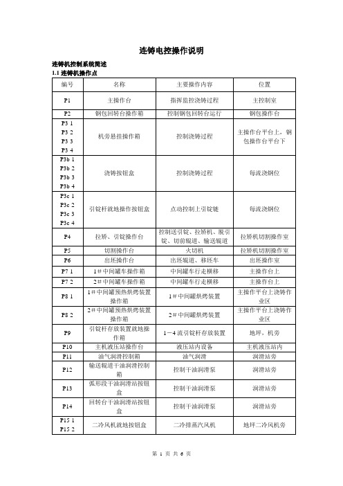
连铸电控操作说明连铸机控制系统简述1.2 钢包回转台控制钢包回转台正常驱动采用一台电机,变频调速。
事故驱动采用液压马达。
钢包回转台在P2操作箱上进行控制,主要控制内容有:“反转”“停”“正传”选择开关;“慢速反转”“慢速正传”带点动按钮;“事故回转”按钮。
1.3 大包加盖装置控制大包加盖装置共有两套。
分别采用电液推杆驱动。
1#加盖装置和2#加盖装置分别在P2上进行控制。
控制内容有:“加盖”“开盖”带灯按钮,“停”按钮;“升”“降”带灯按钮。
1.4 中间罐车控制中间罐车驱动采用二台变频调速电机。
中间罐车主要在P7操作箱上进行控制,主要控制内容有:中间罐车行走“左行”“停”“右行”选择开关;“点动”“点退”点动按钮。
中间罐车点动主要用于在浇注位水口对中。
中间罐升降“上升”“停”“下降”选择开关;“水平调整”带灯按钮。
中间罐横移“前移”“后移”带灯按钮。
1.5 二冷室排汽风机控制二冷室排汽风机共有两套。
各由一台电机驱动。
二冷室排汽风机主要在主控室PC工作站和P15操作箱上进行控制,在P15操作箱上可以选择操作地点。
控制项目有:风机“开”“停”按钮。
风机“就地”“远程”选择开关。
1.6 二冷水喷淋系统控制二冷水系统主要有以下检测、控制设备组成:总管压力检测;总管温度检测;每流支管气动切断阀;每流O段流量检测和电动调节阀调节,每流Ⅰ段流量检测和电动调节阀调节,每流Ⅱ段流量检测和电动调节阀调节,每流Ⅲ段流量检测和电动调节阀调节。
二冷水设二种工作方式选择:自动-手动。
自动方式下随“浇铸”、“停浇”按钮一起启动、停止,手动控制有开-关控制,在P3箱上操作。
二冷水调节系统的控制:二冷水调节系统的控制在主控室PC操作站上进行,通过计算机画面可以选择二冷水调节方式:自动方式-半自动方式-手动方式。
流量设定、阀门开度设定均可通过计算机画面进行。
(1)控制原则二冷水各段独立自成系统。
在浇铸前操作工根据浇铸的铸坯断面及钢种选定冷却组别,计算机自动调用配水模型进行生产。


中继顶压站设备操作规程模版一、设备操作准备阶段1. 操作人员需穿戴符合安全要求的个人防护装备。
2. 确保设备操作前已经进行必要的检查和维护工作,确保设备良好的运行状态。
3. 操作人员应熟悉设备的使用说明和操作规程。
二、设备开启操作阶段1. 按照操作人员手册的要求,将设备电源开启。
2. 检查设备是否正常运行,包括显示屏是否正常、警报器是否正常等。
3. 经过确认设备正常后,可以开始进行下一步操作。
三、设备操作过程1. 操作人员需按照要求进行各项设备设置和调整操作。
2. 在设备运行过程中,需要时刻关注设备运行状态和指示值,以及相关的警报信息。
3. 在操作过程中,确保设备操作平稳、准确,不得发生任何异常操作。
四、设备操作结束阶段1. 当设备使用完毕或需要停止运行时,操作人员需按照操作手册的要求进行关闭操作。
2. 关闭设备电源前,需要进行设备的清洁和检查工作,确保设备的整洁和正常。
3. 关闭设备电源后,及时进行设备的记录工作,包括设备运行时间、工作状态等。
五、设备操作安全注意事项1. 操作人员在操作过程中要注意自身安全,严禁戴手套、长袖衣物等。
2. 在操作过程中严禁擅自改变设备设置和参数,只能按照规程进行操作。
3. 在设备运行过程中,不得随意触摸设备内部部件,除非得到相关指令。
4. 若设备发生异常情况,操作人员应立即停止操作,并及时向相关人员报告。
5. 每次操作完成后,设备操作人员应做好设备的记录和整理工作。
六、设备操作责任分工1. 设备操作人员负责设备的日常操作和维护工作。
2. 设备管理员负责设备的保养和维修工作。
3. 管理层负责设备操作规程的制定和监督工作。
七、违章操作处理措施1. 对于违反设备操作规程的行为,将按照公司规定给予相应的纪律处分。
2. 对于造成安全事故或设备损坏的行为,将依据公司相关规定进行处理。
3. 对于频繁违反规程并且经教育无效的操作人员,将被视为不适合从事设备操作工作。
八、附则1. 本规程的解释权归公司所有。

国义钢铁集团公司2#转炉炼钢基础自动化控制系统操作说明书唐山阿诺达自动化公司二零零七年七月目录一、系统说明 (2)二、系统供电操作 (3)三、转炉设备运行操作 (3)四、计算机操作站图形监控 (18)五、使用、维护注意事项 (19)一、系统说明1.概述本系统是国义钢铁有限公司2#转炉炼钢生产计算机自动控制系统。
基础自动化PLC控制站由德国SIEMENS公司的S7-400可编程控制器组成,S7-400是一种模块化大中型PLC系统,它的模块化、无排风扇结构、易于实现分布、易于用户掌握等特点使得S7-400成为各种大中规模控制要求控制任务的方便的解决方案。
系统通过SIEMENS公司的以太网接口将PLC站以及基础自动化计算机操作站组成工业以太网,并由SIEMENS图形监控软件WINCC和编程软件STEP7实现对工业过程的实时监控。
国义钢铁有限公司转炉炼钢自动控制系统主要内容包括:转炉倾动控制、氧枪升降控制、散装料称量控制,氧枪横移控制、开关氧、氮控制、炉下车控制等。
2.系统构成国义转炉炼钢自动控制计算机网络系中包括四个站:三台计算机操作站,一台PLC站,整个网络由以太网络连接。
转炉PLC控制站负责电气设备和过程回路的控制、数据收集。
中央处理器是CPU414-2框架以及4扩展框架。
计算机操作站通过通讯网络将PLC控制站采集的信息集中,对转炉炼钢生产过程进行生产管理、工艺过程和设备运行监控、数据处理、设定操作、系统报警及记录,还可以对网络上各PLC 控制站在线或离线编程,对系统进行组态和维护。
3.系统软件计算机操作站安装有图形监控软件WINCC、PLC编程软件STEP7、计算机系统软件等。
各PLC控制站的中央处理器内存中安装有各PLC控制站的应用软件。
4.控制柜、操作台、操作箱参见原理图的有关表述。
二、系统供电操作2.1 系统供电由用户提供单路380V供电至进线柜,通过此配电柜实现对转炉自动控制系统其它箱柜及设备供电。
CLF170100辊压机安装、使用、维护说明书工作原理CLF系列辊压机主要由电动机、行星减速器、辊系、机架、扭矩轴承、液压加压装置、润滑装置、喂料装置、辊罩、控制系统等组成,辊压机的两个辊轴分别由电动机经万向联轴器、行星减速机带动。
行星减速机安装在扭矩轴承上,与辊子间用缩紧盘联接。
辊系分为活动辊系和固定辊系,两个辊系都安装在机架上,活动辊系可在机架导轨上作水平运动,活动辊系两端共有两个(或四个)平行液压缸对辊系的轴承座施加压力,该压力通过辊系作用在通过两辊轴间的物料上,使物料被破碎、粉磨,并最终被压成料饼。
辊轴采用高强锻钢,辊子外圆堆焊了耐磨合金以保证辊子的经济寿命。
液压系统由液压缸、液压站、蓄能器、阀件等组成。
辊子间隙、油缸压力、轴承温度、减速器温度等都有传感器监测,并配备专门设计的自动控制系统。
CLF170100辊压机概述辊压机可用于挤压符合以下经认可的工艺条件的原料。
将此设备用于其它本手册未列明的用途将被视为滥用。
制造商将不对任何滥用所造成的后果负责,其风险由客户自己承担。
技术参数CLF170100辊压机技术参数表辊压机系统的入料控制辊压机必须作为整个工艺系统框架中的一个运行设备来看待。
只有当整个系统的其他设备和现场装备完好运行,能够达到辊压机的理想要求时,辊压机才能令人满意地发挥其不可或缺的功效。
1.金属的控制在辊压机入料中不可避免的存在各种各样的金属杂质,这对辊压机的使用造成的极大的威胁,过大(大于10mm)的金属杂质将直接损坏辊压机的辊面,而小颗粒的杂志富积后,会额外增加辊压机辊面的磨损,故在设计和使用中要尽最大的可能减少金属杂质的存在。
在设计时,在物料的进料皮带上要设计除铁器和除铁皮带,尽可能的减少入料的金属含量,并在辊压机循环系统中设置金属探测仪,发现超除规定大小的金属进入辊压机。
在操作中,首先要保证除铁器和金属探测仪的正常使用,其次要防止小颗粒的金属的富积,当系统设有如磨旁路时,应定期将循环物料旁路入磨;若系统未设入磨旁路时,应定期清空恒重仓内的物料。
Document ID: UM-IT-1581-20171004Index TableModel 1581Installation, Operating and Maintenance InstructionsBlack & Webster Products Division545 Hupp Ave. P.O. Box 831, Jackson, Michigan 49204Phone: (517- 787-9444 Fax: (517) 787-7585Email:**********************2009Table of Contents Warranty (3)Table Hook-Up (3)Sequence of Operation (3)Table Adjustments (4)Maintenance (5)Tool Mounting Instructions (5)Parts List........................................................................................................6-8 Dimensions......................................................................................................9-10 Piping Schematic.. (11)Table Motion Lay out (12)Document ID: UM-IT-1581-20171004Revision: AWarrantyAir-Hydraulics, Inc. warrants to the original user that all products manufactured will be free from defects in material and workmanship and will possess the characteristics represented in writing. Claim for breach of the above warranty must be made within a period of one year from date of delivery to the user. Upon satisfactory proof of claim, we will make any necessary repairs or corrections, or at our discretion, replace defective parts at the factory, transportation charges prepaid. Charges for correcting defects will not be allowed, nor can we accept goods returned for correction unless we are notified in writing and the return or correction is authorized by Air-Hydraulics, Inc. in writing. The foregoing is in lieu of all other warranties, expressed or implied, including any warranties that extend beyond the description of the product. This paragraph sets forth the extent of our liability for breach of any warranty in connection with the sale or use of our products. It is understood we will not be liable for consequential damages such as loss of profit, or expense, whether based on tort or contract. This warranty is void if the articles covered by the warranty have not been properly installed, maintained and used.Table Hook-UpAir-Hydraulics Inc. recommends that the air line supplying the table be at least 1/2” pipe or 1/2” ID hose. The maximum pressure is 110 p.s.i. Anything above this could be dangerous to the machine operator and/or other personnel.Refer to the schematic on page when plumbing controls for table hook-up. One 1/2” NPT 2-position, 4-way valve controls the index cylinder and locking cylinder. Care should be taken not to restrict flow to the table.When checking the table to operation after hook-up, make sure the table is held securely (clamped or bolted). The table can shift or jump if left loose on bench.Sequence of Operation1.The directional control valve is shifted by the pilot or solenoid signal. This causes the lockingcylinder to retract, unlocking the table. Note: The signal to the solenoid or pilot must bemaintained until the table top has completed its movement.2.With the locking cylinder clear of the index ring, the index cylinder retracts, moving the index armwhich then turns the table top.3.After the index cylinder is fully retracted, the directional control valve is shifted back which forcesthe locking cylinder forward and locks the table into position. When the locking cylinder locksthe table into place, it pushes the index pawl out of the index ring.4.With the index pawl clear of the index ring, the index cylinder moves forward until it hits the stoprod. With the stop rod adjusted properly, the index pawl is spring actuated into the next slot on the index ring and the index cycle is complete.5.The index table is now ready for the next index cycle.Note: If using a manual operation to shift the directional control valve that controls the index cylinder, insure to hold the valve fully shifted until the table stops moving as a built-in cushion for the index cylinder slows the movement of the table just before the cylinder is fully retracted. If the valve is released too soon, the locking cylinder may not be able to engage the locking ring. If the table is not locked, the table top will return to its original position.Table AdjustmentsAir-Hydraulics, Inc. index tables are built, tested and adjusted at the factory prior to shipment. After receipt of the table, you may find minor adjustments are required to meet your operational requirements.The first adjustment should be in the general speed of the table during the index. To increase the indexing speed of the table, turn the speed control on the index cylinder counter-clockwise & clockwise to decrease. Care must be taken not to set the speed of the table so high that the cushion will not be able to slow the cylinder.The second adjustment is the cushion. Turning the cushion adjustment screw in the clockwise direction increases the amount of cushioning and counter-clockwise decreases the amount of cushioning. The cushion should be set so a visible slowing of the table top occurs just prior to stopping. Do not operate the index table with the cushion not functioning. Possible damage can occur if there is insufficient cushioning of the tabletop.The third adjustment is the override stop. This stop aligns the notch in the index ring with the locking cylinder plunger. If movement in the table is detected when the locking cylinder plunger engages into the index ring, loosen the large jam nut on the override stop-bolt. Make minor changes clockwise or counter-clockwise until the movement is eliminated and then re-tighten the jam nut.Adjustment of the stop-rod should not be necessary as it has been adjusted at the factory. In the event of the table being disassembled for repair or maintenance, it may become necessary to adjust. The stop-rod is used to adjust the point where the index pawl drops into a slot in the index ring and is ready to index the table top. If the stop-rod is inadvertently moved, use the following procedure to readjust the stop-rod. Remove connections for the power source from the index table; loosen the jam nut on the stop-rod until there is approximately 1-1/2” of threads showing. Make sure the table is in position to be locked and then apply power to the back of the locking cylinder. With the signal maintained to the locking cylinder, pressurize the back of the index cylinder and slowly turn the stop-rod in a clockwise direction until the pawl drops into a slot in the ring. If the table is locked up, the stop-rod will not be able to be turned when the pawl drops in the slot. Turn the stop-rod in a counter-clockwise direction ¼ to ½ turns and tighten the jam nut. The index cylinder stroke should be correct, allowing the pawl to drop into a slot every cycle.MaintenanceIn order to extend the life of the table and achieve maximum efficiency, it is recommended that all seals and gaskets be changed on a yearly basis. When changing seals and gaskets it is also recommend that the index pawl and pawl return spring be changed at the same time. After repeated index cycles, the effectiveness of the pawl return spring is lessened.A regular lubrication schedule is recommended to maintain accuracy and reliability in the index table. Grease fittings are supplied and should be greased (1-2 pumps) with a good quality lithium grease on a weekly basis to start. Take care not to over lubricate the table. Excess grease will accumulate inside of the table and will cause internal parts to move slower due to increased friction.It is recommended that at least one complete seal kit be stocked to repair your table. Seals and gaskets are sold in complete sets only.If any problems are encountered with your table, feel free to call Air-Hydraulics, Inc., Jackson, Michigan, and someone in our service department will be glad to assist you. If a comprehensive maintenance program suited for your application is desired, we can also help you set up a program.Instructions for Mounting Tooling to Air-Hydraulics Inc. Indexer1.Mount table to the machine where the drilling, tapping, reaming, etc. is to be done. If the sub-plate has already been installed by the factory, remove it from the index table.2.Connect the power source to the table with the proper valving according to the schematic andinstructions provided.3.Index the table to insure proper operation. The table must be in the locked position prior tomachining.4.Indicate sub-plate mounting holes from the center hole of the table spindle (.750” dia.). Locate thebolt and dowel pin holes from the drawing provided by Air-Hydraulics, Inc.Caution: Holes in the table top must not break through to the table base. A maximum depth of 7/8” is recommended. Use a bottom tap for 3/8-16 UNC tapped holes.5.Install the sub-plate on the table.6.Perform the work required to install tooling, tooling nests, clamps, etc. on the sub-plate at theposition required.7.Index the table and repeat step (#6) until all tooling holes are installed.8.After all holes are drilled, tapped, reamed, etc., install tooling.9.Remove the table from the drilling machine and position on the machine where it is to be used.With the table in the locked position, locate it in the desired location for machine operation.Attach the table to the plate of the machine.Note: Air-Hydraulics, Inc. recommends that the table and fixtures be doweled in place to insure repeatability.Model 1581 Parts Drawing/List1581 Index Table Parts ListNote: When ordering replacement parts for this table, specify Model 1581 and serial number. Air-hydraulics cannot be held responsible for parts shipped in error if the model and serial number are not supplied.Continued on next page.1581 Index Table Parts List – Continued* All O-rings and gaskets and seals are sold collectively as a kit. The part number is: T1581-CS.Model 1581 DimensionsModel 1581 Dimensions ContinuedDocument ID: UM-IT-1581-20171004。
1 系统概述上海汽轮机〔STC〕消费的这套危急遮断保护系统〔ETS〕,为大型汽轮发电机组的运行装备了平安可靠的保护装置,当存在某种可能导致机组受损害的危险情况时,该套装置可使汽轮机自动遮断,保护机组的平安。
ETS装置通过各传感器监测着汽轮机的运行情况。
详细监测的参数为:•汽机超速110%〔OS〕•EH油压低〔LP〕•光滑油压低〔LBO〕•冷凝器真空度低〔LV〕•推力轴承磨损〔轴向位移TBW〕•由用户决定的遥控遮断信号〔REM〕该装置还具有以下功能:•各通道在线试验并不会导致汽轮机正常遮断误动或拒动。
•任一元件出故障不会导致汽轮机因误动作而遮断。
•任意某个元件故障时,仍可检测出有效的汽轮机遮断情况并能成功地遮断汽轮机。
该套ETS装置有一个控制柜,控制柜中有两套可编程逻辑控制器〔PLC〕组件,一个超速控制箱,其中有三个带处理和显示功能的转速继电器,一个交流电源箱,一个直流电源箱以及位于控制柜反面的二排输入输出端子〔U1-U4〕。
PLC组件是由两套独立的PLC组件组成:主PLC〔MPLC〕和辅助PLC〔BPLC〕,这些PLC组件采用智能遮断逻辑,必要时提供准确的汽轮机遮断,每一组PLC均包括处理器卡〔CPU〕和I/O接口卡,CPU含有遮断逻辑,I/O接口组件提供接口功能,上面一排处理器构成MPLC,提供全部遮断、报警和试验功能。
下面一排处理器为BPLC,是含有全部遮断功能的冗余的PLC单元;假设主PLC故障,它仍继续运行并具有遮断功能。
三个转速继电器均可以将独立的磁阻发送器的输入信号进展数字处理,并且当转速超过继电器设定点时,继电器的触点断开。
在每个转速继电器中有二个转速设定点触发二个独立的继电器,并提供转速指示,SP1为正常超速设定点,通常被设定为额定转速的110%,SP2定义进步的超速设定点,通常设定为额定转速的114%。
三只磁阻传感器探头探测转速。
当PLC逻辑指示出三个转速继电器中有两台转速超出,PLC就发出超速信号遮断汽轮机,这样可以防止因一个传感器或转速继电器出故障,导致不当的汽轮机遮断或阻止正常的汽轮机遮断。
第一部分:转炉炼钢倾动自动控制系统说明转炉炼钢自动化系统中倾动交流传动装置采用一拖一方式,设四台变频器。
倾动交流传动在控制上最关键的就是电机的力矩同步性。
同步性的准确的控制是倾动交流传动达到最佳状态的关键,对四台变频器的工作状态进行采集,通过PLC对采集信号进行分析处理后,调整变频器输出,使四台变频器输出达到同步状态。
转炉倾动角度确定采用绝对型编码器,其安全性和准确性大大超越传统的主令控制器。
首先,编码器安装方便,调整简单,使用寿命长;其次,编码器精度高,单圈分度为1024,即倾动角度可精确到0.044度,这是主令控制方式望尘莫及的,使转炉本体旋转时各个位置都能精确反映,不存在位置的盲点。
重点提示:在正式操作前,要进行一些必要的检查。
●按下操作台上的“灯检查”按钮,观察操作台上的指示灯是否有损坏,如果有损坏请及时更换。
●切换监控画面,观察监控数据和电脑(包括鼠标,键盘,显示等)工作是否正常,如果有异常现象请及时和专业人员联系。
倾动操作及连锁:倾动本体控制方式为手动控制和自动控制,可在三地进行操作,分别是主控操作、炉前操作操作和炉后操作;⏹倾动主控台操作:●作倾动。
其功能和权利与炉前是一样。
●BCD数字显示表,刷新频率为20次/秒,同步显示倾动角度,范围为179~-180。
●倾动操作可在主控室和炉后两地进行操作,操开关打到右侧时倾动操作权被分配到主控操作,开关打到左侧时倾动操作权被分配到炉后操作。
●置自动转回到零角度的位置。
倾动自动回零位过程中,加速,减速,停止,全部自动,可以快速准确的使本体停止到零角度的位置,减轻操作人员的工作量。
●本体向倒渣方向旋转。
●态,即可以操作倾动旋转。
⏹倾动炉前操作台及炉后操作台操作,炉前和炉后操作台只是位置不同,操作方式是相同的,操作方法:●态,即可以操作倾动旋转。
●:抱闸抱紧停车,进线接触器自动按钮,进线接触器自动吸合,倾动变频器上电,才可以再次动作倾动。
●本体向倒渣方向旋转。