夏普GP2Y1010AU0F_粉尘传感器参考程序
- 格式:doc
- 大小:169.11 KB
- 文档页数:4
PM2.5粉尘颗粒检测仪的研制【摘要】PM2.5粒径小,含有大量的有毒、有害物质,严重影响人体健康。
PM2.5粉尘颗粒的即时检测,是有效防治PM2.5污染的前提和重要保障。
本文介绍了PM2.5粉尘颗粒检测仪的研制方法,主要包括设计原理、结构组成、技术指标等。
【关键词】PM2.5;灰尘传感器;单片机;A/D转换1.引言PM2.5是指大气中直径小于或等于2.5微米的颗粒物,也称为可入肺颗粒物。
PM2.5粒径小,富含大量的有毒、有害物质且在大气中的停留时间长、输送距离远,因而对人体健康和大气环境质量的影响很大。
据有关部门统计调查显示,2012年北京、上海因PM2.5污染分别造成早死人数为2349、2980人,分别占当年死亡总人数的比例为1.9%、1.6%,经济损失分别为18.6、23.7亿元。
而2012年北京、上海因交通意外死亡人数分别为974人和1009人。
可见,PM2.5对人类的危害极大。
PM2.5粉尘颗粒的即时检测,是有效防治PM2.5污染的前提和重要保障。
为此,本文介绍了PM2.5粉尘颗粒检测仪的研制方法,主要包括设计原理、结构组成、技术指标等。
PM2.5粉尘颗粒检测仪可用于:室内、汽车内空调排风口粉尘浓度检测;环保监测部门大气飘尘检测,污染源调查;建筑或爆破等生产现场粉尘浓度的测定;精密仪器等高清洁生产环境的空气检测等。
2.PM2.5粉尘颗粒检测仪的设计原理PM2.5粉尘颗粒检测仪设计原理如下:灰尘传感器实时的检测空气中直径小于或等于2.5微米的颗粒物的含量,并根据含量比例输出模拟电压信号,该信号经过A/D转换后,由单片机进行采集、计算、数据处理后,在LED显示屏上,显示出PM2.5的数值。
当PM2.5超过仪器设定值时,产生声光报警,并存储当前PM2.5值和时间参数等。
3.PM2.5粉尘颗粒检测仪的结构组成PM2.5粉尘颗粒检测仪(如图1)由单片机、灰尘传感器单元、用户输入单元、A/D转换单元、LED显示屏、电源单元、监控复位单元、时钟单元和报警单元等九部分构成。

Dust Sensor灰尘传感器用户手册1.特性和原理本模块是以夏普GP2Y1010AU0F为核心的灰尘传感器。
传感器内部的红外二极管,可以输出一个跟灰尘浓度成线性关系的电压值。
通过该电压值即可计算出空气中的灰尘和烟尘含量。
测量对象:直径大于0.8μm灰尘颗粒有效量程:500μg/m3输出类型:电压模拟量工作电压: 2.5V~5.5V产品尺寸:63.2mm×41.3mm固定孔尺寸: 2.0mm通气孔尺寸:9.0mm1.1.传感器输出特性传感器输出电压与灰尘浓度关系在0到0.5mg/m3范围内成线性关系,如下图所示:图1: 传感器输出特性曲线1.2.传感器控制原理1)通过设置模块I LED引脚为高电平,从而打开传感器内部红外二极管。
2)等待0.28ms,外部控制器采样模块A OUT引脚的电压值。
这是因为传感器内部红外二极管在开启之后0.28ms,输出波形才达到稳定。
如下图所示:图2: I LED与红外二极管输出波形关系3)采样持续0.04ms之后,再设置I LED引脚为低电平,从而关闭内部红外二极管。
4)根据电压与浓度关系即可计算出当前空气中的灰尘浓度,具体实现细节请参考Demo程序。
注:输出的电压经过了分压处理(查看原理图),要将测得的电源放大11倍才是实际传感器输出的电压。
1.3.主要用途检测空气中灰尘浓度,用于空气净化器、空气质量监测仪、PM2.5检测仪等。
2.操作和现象2.1.传感器接口说明表1: 传感器接口说明2.2.连接开发板使用下面章节以四款不同类型的开发板为例,描述具体操作步骤及实验现象。
2.2.1.Open103R(主控芯片STM32F103R)1)编译下载Demo程序。
2)3)表2: 传感器和Open103R引脚对应关系4)开发板上电,可看到串口助手不断显示当前灰尘浓度值,当有大量灰尘颗粒进入通气孔时,数据发生明显变化,实验现象见附录。
2.2.2.Open407Z-C(主控芯片STM32F407Z)1)编译下载Demo程序。
开发控制板组成,
GP2Y1010AU0FC01模块使用说明书
一, 简介
1,该模块由夏普粉尘传感器GP2Y1010AU0F 和模块型号是:GP2Y1010AU0FC01,模块经过精确标定后,检测空气中的粉尘浓度,精度高,一致性强。
2,传感器智能校准:当灰尘附着于传感器或传感器老化时,系统会自动进行浓度参数校准,确保测量的准确性。
3,提供多种浓度值输出接口:模拟电压输出:灰尘浓度越高,输出模拟电压越高。
数字串口输出;供其它平台MCU 直接读取。
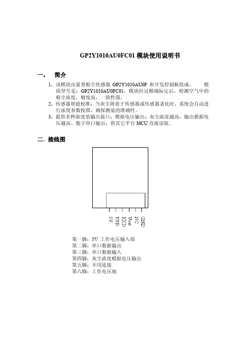
二,接线图
第一脚:5V 工作电压输入端
第二脚:串口数据输出
第三脚:串口数据输入
第四脚:灰尘浓度模拟电压输出
第五脚:不用连接
第六脚:工作电压地
三,技术参数
四,通信协议命令格式
1,模块读取除尘机工作状态:
传感器发送命令格式:05FEF603
除尘机收到上述命令后返回工作状态
①除尘机处于开机状态:返回数据格式06FEF103
②除尘机处于关机状态:返回数据格式06FEF003
2,除尘机读取灰尘浓度值:
除尘机发送命令格式:05FEF503
模块收到上述指令后返回浓度值。
返回数据格式:06ABCD03
浓度计数方法:浓度值(十六进制)=0XABCD(ug/m3)。
例如AB=01,CD=0X23:则
浓度(十六进制)=0X0123(ug/m3)
浓度(十进制)=291(ug/m3)。
空气粉尘浓度检测器电路设计与软件编程论文空气粉尘浓度检测器电路设计与软件编程论文本设计以ATmega382p单片机为控制中心,由GP2Y1010AU0F 光学空气质量传感器测量空气粉尘浓度,通过单片机内置的10位A/D 转换将模拟的电压信号转换成数字信号,得到粉尘浓度值,并由LCD1602显示屏显示出来。
同时,设置浓度预警值并同测量值一起显示在显示屏上。
当测量浓度超过预警值时,仪器就会报警。
0 引言随着人类工业和经济的快速发展,我们的环境污染越来越严重。
除废气、废水外,颗粒状粉尘、烟尘向大气排放所造成的污染已成为一个十分突出的问题。
PM2.5,PM10,PM0.1及其吸附的重金属粒子是雾霾的重要组成部分[1]。
2012年2月,《环境空气质量标准》新增了对PM2.5的检测指标,PM2.5成为空气质量标准之一。
数据表明,我国空气质量超标的城市中68%都存在可吸入颗粒物的问题[2]。
由此可以看出粉尘对人类健康和生产的危害十分严重。
所以,粉尘浓度的检测和控制具有重要的意义。
1 系统工作原理单片机选用ATmega328p,粉尘浓度传感器选用夏普GP2Y1010AU0F灰尘传感器,按键部分通过电阻与按键串联将信号输入模拟口,通过读取模拟值的不同判断按键值,显示部分采用LCD1602并用采取I2C总线的8位远程I/O扩展口芯片PCF8574进行引脚简化。
将粉尘检测器电源开关打开,当传感器得到一个由粉尘浓度转换得来的0~5V的`电压信号时,进入单片机,经过处理后转变为十进制数通过I/O口在显示屏上显示出精确数值。
数值量随输入电压的扰动而变化。
同时键盘设定预警值送入单片机,与测量值一同显示出来。
当采集的当前粉尘浓度大于预警值时,单片机驱动蜂鸣器报警。
2 系统电路设计2.1 电路总体设计以ATmega328p单片机为核心,主要包括单片机处理模块,信号采集模块,独立按键模块,显示模块和蜂鸣器报警模块。
系统通过信号采集模块采集空气中的粉尘,得到0~5V的电压信号后,由单片机内部自带的10位ADC进行模数转换得到粉尘浓度,与此同时,通过独立按键模块设定浓度预警值,通过液晶显示模块将粉尘浓度和预警值同时显示在显示屏上。
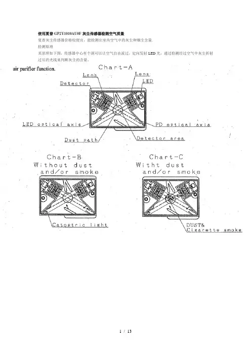
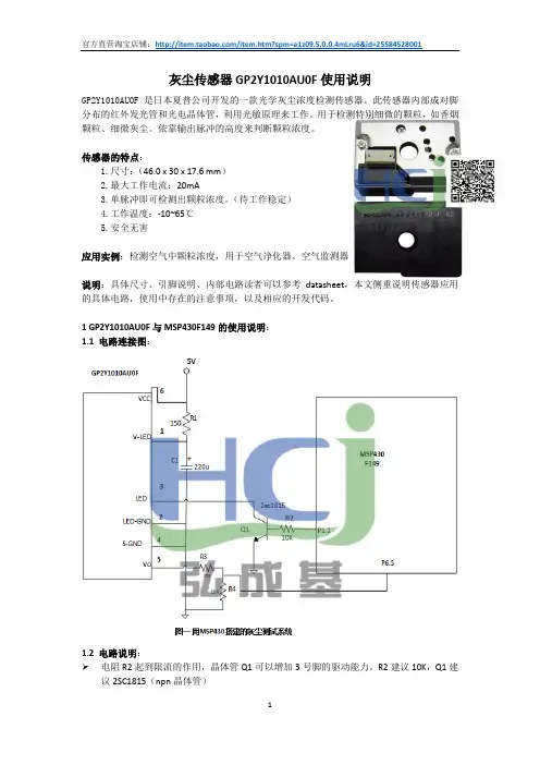
使用夏普GP2Y1010AU0F灰尘传感器检测空气质量夏普灰尘传感器价格较便宜,能检测出室内空气中的灰尘和烟尘含量.检测原理其原理如下图,传感器中心有个洞可以让空气自由流过,定向发射LED光,通过检测经过空气中灰尘折射过后的光线来判断灰尘的含量。
电路图因为数据是通过pin 5的电压模拟信号输出的,而树莓派的引脚不支持模拟信号直接读取(需要增加数模转换芯片),所以先用Arduino来实验。
Arduino 代码根据电路图,把Arduino和传感器连接起来:1.Sharp pin 1 (V-LED) => 5V 串联1个150欧姆的电阻(最好在电阻一侧和GND之间再串联一个220uf的电容)2.Sharp pin 2 (LED-GND) => GND3.Sharp pin 3 (LED) => Arduino PIN 2 (开关LED)4.Sharp pin 4 (S-GND) => GND5.Sharp pin 5 (Vo) => Arduino A0 pin (空气质量数据通过电压模拟信号输出)6.Sharp pin 6 (Vcc) => 5V1./*2.Interface to Sharp GP2Y1010AU0F Particle Sensor3.Program by Christopher Nafis4.Written April 20125.6.7.8.9.Sharp pin 1 (V-LED) => 5V (connected to 150ohm resister)10.Sharp pin 2 (LED-GND) => Arduino GND pin11.Sharp pin 3 (LED) => Arduino pin 212.Sharp pin 4 (S-GND) => Arduino GND pin13.Sharp pin 5 (Vo) => Arduino A0 pin14.Sharp pin 6 (Vcc) => 5V15.*/16.#include<SPI.h>17.#include<stdlib.h>18.19.int dustPin=0;20.int ledPower=2;21.int delayTime=280;22.int delayTime2=40;23.float offTime=9680;24.25.int dustVal=0;26.int i=0;27.float ppm=0;28.char s[32];29.float voltage=0;30.float dustdensity=0;31.float ppmpercf=0;32.33.void setup(){34.Serial.begin(9600);35. pinMode(ledPower,OUTPUT);36.37.// give the ethernet module time to boot up:38. delay(1000);39.40. i=0;41. ppm=0;42.}43.44.void loop(){45. i=i+1;46. digitalWrite(ledPower,LOW);// power on the LED47. delayMicroseconds(delayTime);48. dustVal=analogRead(dustPin);// read the dust value49. ppm=ppm+dustVal;50. delayMicroseconds(delayTime2);51. digitalWrite(ledPower,HIGH);// turn the LED off52. delayMicroseconds(offTime);53.54. voltage=ppm/i*0.0049;55. dustdensity=0.17*voltage-0.1;56. ppmpercf=(voltage-0.0256)*120000;57.if(ppmpercf<0)58. ppmpercf=0;59.if(dustdensity<0)60. dustdensity=0;61.if(dustdensity>0.5)62. dustdensity=0.5;63.String dataString="";64. dataString+=dtostrf(voltage,9,4,s);65. dataString+=",";66. dataString+=dtostrf(dustdensity,5,2,s);67. dataString+=",";68. dataString+=dtostrf(ppmpercf,8,0,s);69. i=0;70. ppm=0;71.Serial.println(dataString);72. delay(1000);73.}把传感器和Ardiuno连接好后,可以连续打印出传感器的输出电压值。
届.别.2016届学号毕业设计基于51单片机的PM2.5检测系统的设计与实现姓名系别、专业电子信息与电气工程学院电子信息科学与技术专业导师姓名、职称完成时间 2016年5月10日目录摘要 (I)Abstract (I)1 绪论 (1)1.1 课题背景 (1)1.2 国内外研究现状 (1)2 系统仿真软件与总体设计方案 (1)2.1 Keil4软件开发坏境 (1)2.2 软件烧录工具 (2)2.3程序结构分析 (4)2.4 整体的设计方案 (4)2.5电源模块 (4)3 主要元器件简介43.1 GP2Y1010AU0F传感器简介 (5)3.2 ADC0832模数转换器简介 (7)3.3 LCD1602液晶显示屏 (10)3.4 STC89C52单片机的简介 (12)4 系统单元电路模块设计 (15)4.1主控制模块 (15)4.2显示模块电路 (16)4.3关于报警模块的设计 (16)4.4按键模块的设计 (17)4.5粉尘模块电路设计 (17)4.6电源局部的设计 (17)5 系统测试与实现 (18)5.1系统程序流图 (18)5.2 仿真电路 (20)5.3 软件跟硬件结合 (21)5.4 测试结果分析 (23)5.5 系统实现 (23)6、总结 (24)致谢 (24)参考文献 (25)附录1:系统整体电路原理图 (26)附录2:系统设计局部源程序 (27)摘要现在社会开展的越来越快,随着工业的开展,虽然给人们的生活带来很多便利。
但是,在生产过程产生很多对人体有害的因素工业生产过程中会,例如煤炭灰开采、水泥生产等行业中的粉尘污染。
我的设计采用由LCD1602液晶模块、STC89C52单片机最小系统、ADC0832模数转换器模块、GP2Y1010AU粉尘传感器、电源模块、蜂鸣器报警模块和按键模块模块组成。
单片机是通过ADC0832转换芯片采集GP2Y1010AU粉尘传感器的粉尘的浓度,通过单片机的数据转换处理后在液晶屏上显示空气中的质量,测量空间中的粉尘浓度如果大于当时设置粉尘浓度时,蜂鸣器就会产生报警的声音和发光二极管发出声光报警。
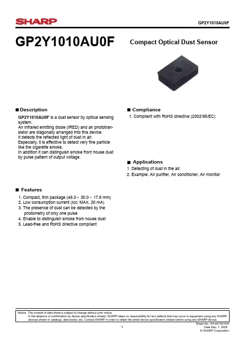
GP2Y1010AU0FGP2Y1010AU0FCompact Optical Dust Sensor■Description■Features■Compliance■Applications1. Detecting of dust in the air.2. Example: Air purifier, Air conditioner, Air monitor1. Compliant with RoHS directive (2002/95/EC)1. Compact, thin package (46.0 × 30.0 × 17.6 mm)2. Low consumption current (Icc: MAX. 20 mA)3. The presence of dust can be detected by the photometry of only one pulse4. Enable to distinguish smoke from house dust5. Lead-free and RoHS directive compliantNotice The content of data sheet is subject to change without prior notice.In the absence of confirmation by device specification sheets, SHARP takes no responsibility for any defects that may occur in equipment using any SHARP devices shown in catalogs, data books, etc. Contact SHARP in order to obtain the latest device specification sheets before using any SHARP device.GP2Y1010AU0F is a dust sensor by optical sensing system.An infrared emitting diode (IRED) and an phototran-sistor are diagonally arranged into this device.It detects the reflected light of dust in air.Especially, it is effective to detect very fine particle like the cigarette smoke.In addition it can distinguish smoke from house dust by pulse pattern of output voltage.■Internal schematic■Outline Dimensions(Unit : mm)V-LEDLED-GND LED S-GND V O V CC123456132654Marking informationDate code (2 digit)1st digit2nd digitYear of production Month of productionA.D.Mark Month Mark2000011200112220022332003344200445520055662006677200778820088992009910X2010011Y::12Z repeats in a 10 year cycleCountry of originPhilippines■■ Absolute Maximum Ratings*1 Open drain drive inputParameter Symbol Rating Unit Supply voltageCC V Operating temperature T T opr −10 to +65°C −0.3 to V CC V −0.3 to +7Input terminal voltage V V LED *1Soldering temperaturesol−20 to +80°CElectro-optical Characteristics■ Recommended input condition for LED input terminalParameter ConditionsSymbol K V OC I LED *1 *2 *3*2 *3*2 *3R L =4.7k Ω*2LED terminal voltage = 0*2R L =∞MIN.0.3503.4−−TYP.0.50.9−1110MAX.1.50.65−2020Unit V/(0.1mg/m 3)V V mA mASensitivityOutput voltage at no dust V OH Output voltage range LED terminal current I CCConsumption current*1 Sensitivity is specified by the amount of output voltage change when dust density changes by 0.1 mg/m 3.And the dust density for detection is a value of the density of cigarette (MILD SEVEN®) smoke measured by the digital dust monitor (P-5L2: manufactured by SHIBATA SCIENTIFIC TECHNOLOGY LTD.).*2 Input condition is shown in Fig. 1*3 Output sampling timing is shown in Fig. 2(T a =25°C)(T a =25°C, V CC =5V)ParameterPulse Cycle Pulse WidthOperating Supply voltageSymbol T P W V CCValue 10 ± 10.32 ± 0.025 ± 0.5Unit ms ms VFig. 1 Input Condition for LED Input TerminalFig. 2 Sampling Timing of Output PulseI LEDRemarks : Please be aware that all data in the graph are just for reference and are not for guarantee.432100.20.40.60.8O u t p u t v o l t a g e (V )Dust density (mg/m 3)Fig. 3 Output Voltage vs. Dust Density●Notes1 Connection of case and GNDCase material use conductive resin as cover case {printed model No.} and metal {test terminal side}as bottom cover. The metal case connects with GND in sensor.2 CleaningPlease don’t do cleaning, because there is a case that this device is not satisfied with its characteristics by cleaning.3 Pulse input rangePlease subject to recommendation as regard input condition for LED in order to keep reliability.4 Dust adhesionThere is a case that this product does not detect the dust density correctly, since the dust adhered to the inside of the dust through hole may project into the detecting space which consist of emitter anddetector light axis. Please take the structure and mechanism of the equipment into consideration toavoid the influence of adhered dust. And when the dust is adhered, please consider the maintenance such as vacuuming or blowing off the dust by air.In addition, please pay attention to structure and placing location of the application to avoid anyadhesive particle like oil, etc. to gets into the device. If it sticks to optical part, malfunction may occur.5 Light outputIn circuit designing, make allowance for the degradation of the light emitting diode output that resultsfrom long continuous operation. (50% degradation/5 years)6 Sensitivity adjustment VRVR for sensitivity adjustment is set up at shipping from sharp. Please do not touch the VR orElectro-optical characteristics specified on the specification will be invalid.7 ResolutionPlease do not disassemble the device such as removing tapping screw and so on. Even if the device is reassembled, it may not satisfy the specification.8 Application to fire alarmPlease do not use this device for a fire alarm application. When using this device to application other than air purifying and equipment with air purifying function, please inform us before usage.9 Noise influenceIf the sensor is located close to noise generator (ex. Electric dust collector, etc. ), the sensor outputmay be affected by leaded noise. On top of that noise from power supply line also may affect thesensor output. When desinging the system, please consider the effect from noise.10 Vibration influenceThe sensor may change its value under mechanical oscillation. Before usage, please make surethat the device works normally in the application.11 Incident light influenceThere is a case that the sensor output may be affected when outer-light comes through dust through hole on printed side. In order to avoid any influence from outer-light, please locate the printed sideof sensor facing to inside of the application.12 When inside of the sensor is moisturized, this product does not keep its proper function. Pleasedesign the application so that moisturization of the sensor does not happen.Sheet No.: E4-A01501EN●Presence of ODC etc.This product shall not contain the following materials.And they are not used in the production process for this product.Regulation substances : CFCs, Halon, Carbon tetrachloride, 1.1.1-Trichloroethane (Methylchloroform) Specific brominated flame retardants such as the PBB and PBDE are not used in this product at all.This product shall not contain the following materials banned in the RoHS Directive (2002/95/EC).• Lead, Mercury, Cadmium, Hexavalent chromium, Polybrominated biphenyls (PBB),Polybrominated diphenyl ethers (PBDE).Packing SpecificationPACKING METHOD1. Each tray holds 50 pieces. Packing methods are shown in (A).2. Each box holds 5 trays. Pads are added to top (B).3. The box is sealed with packing tape. (C) shows the location of the Model number, Quantity, and Inspection date.4. Weight is approximately5.6 kg■Important Notices· The circuit application examples in this publication are provided to explain representative applications of SHARP devices and are not intended to guarantee any circuit design or license any intellectual property rights. SHARP takes no responsibility for any problems related to any intellectual property right of a third party resulting from the use of SHARP's devices.· Contact SHARP in order to obtain the latest device specification sheets before using any SHARP device. SHARP reserves the right to make changes in the spec- ifications, characteristics, data, materials, structure, and other contents described herein at any time without no-tice in order to improve design or reliability. Manufactur-ing locations are also subject to change without notice.· Observe the following points when using any devices in this publication. SHARP takes no responsibility for damage caused by improper use of the devices which does not meet the conditions and absolute maximum ratings to be used specified in the relevant specification sheet nor meet the following conditions:(i) The devices in this publication are designed for use in general electronic equipment designs such as:--- Personal computers--- Office automation equipment--- Telecommunication equipment [terminal]--- Test and measurement equipment--- Industrial control--- Audio visual equipment--- Consumer electronics(ii) Measures such as fail-safe function and redundant design should be taken to ensure reliability and safety when SHARP devices are used for or in connection with equipment that requires higher reliability such as:--- Transportation control and safety equipment (i.e., aircraft, trains, automobiles, etc. )--- Traffic signals--- Gas leakage sensor breakers--- Alarm equipment--- Various safety devices, etc.(iii) SHARP devices shall not be used for or in connec-tion with equipment that requires an extremely high level of reliability and safety such as:--- Space applications--- Telecommunication equipment [trunk lines]--- Nuclear power control equipment--- Medical and other life support equipment (e.g., scuba).· If the SHARP devices listed in this publication fall within the scope of strategic products described in the Foreign Exchange and Foreign Trade Law of Japan, it is necessary to obtain approval to export such SHARP devices.· This publication is the proprietary product of SHARP and is copyrighted, with all rights reserved. Under the copyright laws, no part of this publication may be re-produced or transmitted in any form or by any means, electronic or mechanical, for any purpose, in whole or in part, without the express written permission of SHARP. Express written permission is also required before any use of this publication may be made by a third party.· Contact and consult with a SHARP representative if there are any questions about the contents of this publi-cation.Sheet No.: E4-A01501EN。
夏普灰尘传感器原理夏普灰尘传感器是一种常用于空气质量监测的传感器,可以通过测量空气中的灰尘浓度,判断空气的污染程度。
它是基于光学原理工作的,通过测量光的散射来间接测量空气中的灰尘颗粒数量。
夏普灰尘传感器的原理是利用散射光的特性来测量灰尘浓度。
当光线照射到灰尘粒子上时,由于灰尘粒子的形状和大小不同,光线会发生不同程度的散射。
传感器中的激光二极管发射出一束单色激光,该激光经过准直透镜和散射板,形成一束平行光。
当光线遇到空气中的灰尘粒子时,部分光线会被散射到散射板上的光敏电阻。
散射到散射板上的光线,会被光敏电阻转化为电信号。
夏普灰尘传感器采用了光敏电阻的电阻值与光强成反比的原理。
当光敏电阻接收到较少的光线时,电阻值较高,电流较小;当光敏电阻接收到较多的光线时,电阻值较低,电流较大。
通过测量光敏电阻的电流大小,就可以得到空气中灰尘的浓度。
为了避免其他因素干扰,夏普灰尘传感器采用了光路双光子法。
传感器中设置两个光敏二极管,其中一个光敏二极管用来检测散射光的强度,另一个光敏二极管用来检测透射光的强度。
透射光是指光线通过空气中没有灰尘的部分,达到另一侧光敏二极管上。
通过对比散射光和透射光的强度差异,可以消除其他因素对灰尘浓度测量的影响,提高测量的准确性。
夏普灰尘传感器还通过在光路中加入一个专用滤光片来选择测量特定粒径的灰尘颗粒。
这个滤光片只允许特定波长的光线通过,其他波长的光线则会被滤除。
通过选择适当的滤光片,可以使传感器只测量某一特定粒径的灰尘颗粒,排除其他尺寸颗粒的干扰。
综上所述,夏普灰尘传感器是通过测量光线的散射来间接测量空气中的灰尘浓度。
传感器采用了散射光和透射光之间的差异,以及滤光片的选择,来消除其他因素对测量结果的影响。
这种原理使得夏普灰尘传感器在空气质量监测领域具有较高的准确性和可靠性。

修改记录表 Model no.
日期Ref.
页码内容备注
确认&批准
批准核对核对制定
2014.07.01 - 制定
参考特性数据,测试条件参见“※1”
输
出
电
压
(
V
)
埃濃度(mg/㎥)
3.1 产品外观
GP1051AU0F
公司简介
深圳盛世物联科技有限公司(Shenzhen Sense IoT Technology Co.,Ltd)专业代理推广国际知名品牌环境传感器及半导体元器件产品,是一家由多位环境科学领域的资深人士联合创建的集技术开发与代理分销为一体的高新技术企业。
面向物联传感应用,公司长期致力于室内环境空气品质及有害气体监控产品的技术开发,并提供相关配套的传感器、IC、模块、设备以及行业应用方案支持,技术应用涉及温湿度传感、压力传感、气体传感、加速度传感等监测领域,产品涵盖Freescale、TI、Sharp、GE(Amphenol)安费诺、Silicon Labs、PLX、Micron、Sensirion、SenseAir、ST、City、Honeywell、Measurement(Humirel)精量等国际知名品牌,服务客户遍及石油化工、电力电子、汽车智能、空气净化、楼宇暖通、医药监测、食品安全、现代农业等众多终端。
盛世物联拥有一支经验丰富的专业技术/营销团队,以快速响应您的需求,并一如既往的为您提供最先进的产品技术、最优化的解决方案、最快捷的物流服务和最具竞争力的产品价格服务。
盛世追梦,物联你我!感谢亲一直以来的大力支持,祝商祺!。
gp2y1010au0f工作原理下载提示:该文档是本店铺精心编制而成的,希望大家下载后,能够帮助大家解决实际问题。
文档下载后可定制修改,请根据实际需要进行调整和使用,谢谢!本店铺为大家提供各种类型的实用资料,如教育随笔、日记赏析、句子摘抄、古诗大全、经典美文、话题作文、工作总结、词语解析、文案摘录、其他资料等等,想了解不同资料格式和写法,敬请关注!Download tips: This document is carefully compiled by this editor. I hope that after you download it, it can help you solve practical problems. The document can be customized and modified after downloading, please adjust and use it according to actual needs, thank you! In addition, this shop provides you with various types of practical materials, such as educational essays, diary appreciation, sentence excerpts, ancient poems, classic articles, topic composition, work summary, word parsing, copy excerpts, other materials and so on, want to know different data formats and writing methods, please pay attention!GP2Y1010AU0F工作原理解析1. 简介GP2Y1010AU0F是一款常用的粉尘传感器,广泛应用于空气质量监测和环境保护领域。
多功能 PM2.5检测系统王路;曲伟;胡家骏【摘要】A multifunctional PM2.5 detection system is designed , in order to overcome the problems of high cost and single function of the PM2.5 detectors on markets .PM2.5 concentrations and ambient air temperature are detected by core controller implementation of STC 90C51 micro-controller, dust sensor GP2Y1050AUOF and temperature sensor DS18B20 respectively, and data acquisition, calculation and processing are implemented after A/D conversion .It is achieved to the real-time displayof PM2.5 concentration , temperature and time , and functions of PM2.5 limit alarm, time adjustment and interactive .Test results show:PM2.5 data error tested by the PM2.5 detector in normal outdoor ambient air is ±3μg/m3 , the temperature error is ±1 ℃ th at compared with data announced by the local environmental monitoring department , and walking time accurately .%针对市场上PM2.5检测仪的功能单一和价格昂贵的问题,设计了一款多功能PM2.5检测系统。
产品名称:GP2Y1010AU0F粉尘检测传感器模块
技术参数:
∙电源电压:DC5±2V
∙工作电流:20mA(峰值)
∙灵敏度:0.5V/(0.1mg/m3)
∙最小粒子检出值:0.8微米
∙清洁空气中电压:0.9V 典型值
∙工作温度:-10~65℃
∙存储温度:-20~80℃
∙使用寿命:5年
∙尺寸大小:46mm×30mm×17.6mm
∙重量大小:15g
∙
夏普光学灰尘传感器(GP2Y1010AU0F)在检测非常细的颗粒,如香烟烟雾,是特别有效的,
并且是常用的空气净化器系统。
该装置中,一个红外发光二极管和光电晶体管,对角布置成允许其检测到在空气中的灰尘反射光。
该传感器具有极低的电流消耗(最大20mA,11毫安典型的),可以搭载高达7VDC的传感器。
输出的是一个模拟电压正比于所测得的粉尘浓度,敏感性为0.5V/0.1mg/m3。
检测原理
其原理如下图,传感器中心有个洞可以让空气自由流过,定向发射LED光,通过检测经过空气中灰尘折射过后的光线来判断灰尘的含量。
GP2Y1010AU0FGP2Y1010AU0FCompact Optical Dust Sensor■Description■Features■Compliance■Applications1. Detecting of dust in the air.2. Example: Air purifier, Air conditioner, Air monitor1. Compliant with RoHS directive (2002/95/EC)1. Compact, thin package (46.0 × 30.0 × 17.6 mm)2. Low consumption current (Icc: MAX. 20 mA)3. The presence of dust can be detected by the photometry of only one pulse4. Enable to distinguish smoke from house dust5. Lead-free and RoHS directive compliantNotice The content of data sheet is subject to change without prior notice.In the absence of confirmation by device specification sheets, SHARP takes no responsibility for any defects that may occur in equipment using any SHARP devices shown in catalogs, data books, etc. Contact SHARP in order to obtain the latest device specification sheets before using any SHARP device.GP2Y1010AU0F is a dust sensor by optical sensing system.An infrared emitting diode (IRED) and an phototran-sistor are diagonally arranged into this device.It detects the reflected light of dust in air.Especially, it is effective to detect very fine particle like the cigarette smoke.In addition it can distinguish smoke from house dust by pulse pattern of output voltage.■Internal schematic■Outline Dimensions(Unit : mm)V-LEDLED-GND LED S-GND V O V CC123456132654Marking informationDate code (2 digit)1st digit2nd digitYear of production Month of productionA.D.Mark Month Mark2000011200112220022332003344200445520055662006677200778820088992009910X2010011Y::12Z repeats in a 10 year cycleCountry of originPhilippines■■ Absolute Maximum Ratings*1 Open drain drive inputParameter Symbol Rating Unit Supply voltageCC V Operating temperature T T opr −10 to +65°C −0.3 to V CC V −0.3 to +7Input terminal voltage V V LED *1Soldering temperaturesol−20 to +80°CElectro-optical Characteristics■ Recommended input condition for LED input terminalParameter ConditionsSymbol K V OC I LED *1 *2 *3*2 *3*2 *3R L =4.7k Ω*2LED terminal voltage = 0*2R L =∞MIN.0.3503.4−−TYP.0.50.9−1110MAX.1.50.65−2020Unit V/(0.1mg/m 3)V V mA mASensitivityOutput voltage at no dust V OH Output voltage range LED terminal current I CCConsumption current*1 Sensitivity is specified by the amount of output voltage change when dust density changes by 0.1 mg/m 3.And the dust density for detection is a value of the density of cigarette (MILD SEVEN®) smoke measured by the digital dust monitor (P-5L2: manufactured by SHIBATA SCIENTIFIC TECHNOLOGY LTD.).*2 Input condition is shown in Fig. 1*3 Output sampling timing is shown in Fig. 2(T a =25°C)(T a =25°C, V CC =5V)ParameterPulse Cycle Pulse WidthOperating Supply voltageSymbol T P W V CCValue 10 ± 10.32 ± 0.025 ± 0.5Unit ms ms VFig. 1 Input Condition for LED Input TerminalFig. 2 Sampling Timing of Output PulseI LEDRemarks : Please be aware that all data in the graph are just for reference and are not for guarantee.432100.20.40.60.8O u t p u t v o l t a g e (V )Dust density (mg/m 3)Fig. 3 Output Voltage vs. Dust Density●Notes1 Connection of case and GNDCase material use conductive resin as cover case {printed model No.} and metal {test terminal side}as bottom cover. The metal case connects with GND in sensor.2 CleaningPlease don’t do cleaning, because there is a case that this device is not satisfied with its characteristics by cleaning.3 Pulse input rangePlease subject to recommendation as regard input condition for LED in order to keep reliability.4 Dust adhesionThere is a case that this product does not detect the dust density correctly, since the dust adhered to the inside of the dust through hole may project into the detecting space which consist of emitter anddetector light axis. Please take the structure and mechanism of the equipment into consideration toavoid the influence of adhered dust. And when the dust is adhered, please consider the maintenance such as vacuuming or blowing off the dust by air.In addition, please pay attention to structure and placing location of the application to avoid anyadhesive particle like oil, etc. to gets into the device. If it sticks to optical part, malfunction may occur.5 Light outputIn circuit designing, make allowance for the degradation of the light emitting diode output that resultsfrom long continuous operation. (50% degradation/5 years)6 Sensitivity adjustment VRVR for sensitivity adjustment is set up at shipping from sharp. Please do not touch the VR orElectro-optical characteristics specified on the specification will be invalid.7 ResolutionPlease do not disassemble the device such as removing tapping screw and so on. Even if the device is reassembled, it may not satisfy the specification.8 Application to fire alarmPlease do not use this device for a fire alarm application. When using this device to application other than air purifying and equipment with air purifying function, please inform us before usage.9 Noise influenceIf the sensor is located close to noise generator (ex. Electric dust collector, etc. ), the sensor outputmay be affected by leaded noise. On top of that noise from power supply line also may affect thesensor output. When desinging the system, please consider the effect from noise.10 Vibration influenceThe sensor may change its value under mechanical oscillation. Before usage, please make surethat the device works normally in the application.11 Incident light influenceThere is a case that the sensor output may be affected when outer-light comes through dust through hole on printed side. In order to avoid any influence from outer-light, please locate the printed sideof sensor facing to inside of the application.12 When inside of the sensor is moisturized, this product does not keep its proper function. Pleasedesign the application so that moisturization of the sensor does not happen.Sheet No.: E4-A01501EN●Presence of ODC etc.This product shall not contain the following materials.And they are not used in the production process for this product.Regulation substances : CFCs, Halon, Carbon tetrachloride, 1.1.1-Trichloroethane (Methylchloroform) Specific brominated flame retardants such as the PBB and PBDE are not used in this product at all.This product shall not contain the following materials banned in the RoHS Directive (2002/95/EC).• Lead, Mercury, Cadmium, Hexavalent chromium, Polybrominated biphenyls (PBB),Polybrominated diphenyl ethers (PBDE).Packing SpecificationPACKING METHOD1. Each tray holds 50 pieces. Packing methods are shown in (A).2. Each box holds 5 trays. Pads are added to top (B).3. The box is sealed with packing tape. (C) shows the location of the Model number, Quantity, and Inspection date.4. Weight is approximately5.6 kg■Important Notices· The circuit application examples in this publication are provided to explain representative applications of SHARP devices and are not intended to guarantee any circuit design or license any intellectual property rights. SHARP takes no responsibility for any problems related to any intellectual property right of a third party resulting from the use of SHARP's devices.· Contact SHARP in order to obtain the latest device specification sheets before using any SHARP device. SHARP reserves the right to make changes in the spec- ifications, characteristics, data, materials, structure, and other contents described herein at any time without no-tice in order to improve design or reliability. Manufactur-ing locations are also subject to change without notice.· Observe the following points when using any devices in this publication. SHARP takes no responsibility for damage caused by improper use of the devices which does not meet the conditions and absolute maximum ratings to be used specified in the relevant specification sheet nor meet the following conditions:(i) The devices in this publication are designed for use in general electronic equipment designs such as:--- Personal computers--- Office automation equipment--- Telecommunication equipment [terminal]--- Test and measurement equipment--- Industrial control--- Audio visual equipment--- Consumer electronics(ii) Measures such as fail-safe function and redundant design should be taken to ensure reliability and safety when SHARP devices are used for or in connection with equipment that requires higher reliability such as:--- Transportation control and safety equipment (i.e., aircraft, trains, automobiles, etc. )--- Traffic signals--- Gas leakage sensor breakers--- Alarm equipment--- Various safety devices, etc.(iii) SHARP devices shall not be used for or in connec-tion with equipment that requires an extremely high level of reliability and safety such as:--- Space applications--- Telecommunication equipment [trunk lines]--- Nuclear power control equipment--- Medical and other life support equipment (e.g., scuba).· If the SHARP devices listed in this publication fall within the scope of strategic products described in the Foreign Exchange and Foreign Trade Law of Japan, it is necessary to obtain approval to export such SHARP devices.· This publication is the proprietary product of SHARP and is copyrighted, with all rights reserved. Under the copyright laws, no part of this publication may be re-produced or transmitted in any form or by any means, electronic or mechanical, for any purpose, in whole or in part, without the express written permission of SHARP. Express written permission is also required before any use of this publication may be made by a third party.· Contact and consult with a SHARP representative if there are any questions about the contents of this publi-cation.Sheet No.: E4-A01501EN。
GP2Y1010AU0F11807-0430-980© SHARP CorporationGP2Y1010AU0FCompact Optical Dust Sensor■Description■Features■Compliance■Applications1. Detecting of dust in the air.2. Example: Air purifier, Air conditioner, Air monitor1. Compliant with RoHS directive (2002/95/EC)1. Compact, thin package (46.0 × 30.0 × 17.6 mm)2. Low consumption current (Icc: MAX. 20 mA)3. The presence of dust can be detected by the photometry of only one pulse4. Enable to distinguish smoke from house dust5. Lead-free and RoHS directive compliantNotice The content of data sheet is subject to change without prior notice.In the absence of confirmation by device specification sheets, SHARP takes no responsibility for any defects that may occur in equipment using any SHARP devices shown in catalogs, data books, etc. Contact SHARP in order to obtain the latest device specification sheets before using any SHARP device.GP2Y1010AU0F is a dust sensor by optical sensing system.An infrared emitting diode (IRED) and an phototran-sistor are diagonally arranged into this device.It detects the reflected light of dust in air.Especially, it is effective to detect very fine particle like the cigarette smoke.In addition it can distinguish smoke from house dustby pulse pattern of output voltage.■Internal schematic■Outline Dimensions(Unit : mm)V-LEDLED-GND LED S-GND V O V CC123456132654Marking informationDate code (2 digit)1st digit2nd digitYear of production Month of productionA.D.Mark Month Mark2000011200112220022332003344200445520055662006677200778820088992009910X2010011Y::12Z repeats in a 10 year cycleCountry of originPhilippines■■ Absolute Maximum Ratings*1 Open drain drive inputParameter Symbol Rating Unit Supply voltageCC V Operating temperature T T opr −10 to +65°C −0.3 to V CC V −0.3 to +7Input terminal voltage V V LED *1Soldering temperaturesol−20 to +80°CElectro-optical Characteristics■ Recommended input condition for LED input terminalParameter ConditionsSymbol K V OC I LED *1 *2 *3*2 *3*2 *3R L =4.7k Ω*2LED terminal voltage = 0*2R L =∞MIN.0.3503.4−−TYP.0.50.9−1110MAX.1.50.65−2020Unit V/(0.1mg/m 3)V V mA mASensitivityOutput voltage at no dust V OH Output voltage range LED terminal current I CCConsumption current*1 Sensitivity is specified by the amount of output voltage change when dust density changes by 0.1 mg/m 3.And the dust density for detection is a value of the density of cigarette (MILD SEVEN®) smoke measured by the digital dust monitor (P-5L2: manufactured by SHIBATA SCIENTIFIC TECHNOLOGY LTD.).*2 Input condition is shown in Fig. 1*3 Output sampling timing is shown in Fig. 2(T a =25°C)(T a =25°C, V CC =5V)ParameterPulse Cycle Pulse WidthOperating Supply voltageSymbol T P W V CCValue 10 ± 10.32 ± 0.025 ± 0.5Unit ms ms VFig. 1 Input Condition for LED Input TerminalFig. 2 Sampling Timing of Output PulseI LEDRemarks : Please be aware that all data in the graph are just for reference and are not for guarantee.432100.20.40.60.8O u t p u t v o l t a g e (V )Dust density (mg/m 3)Fig. 3 Output Voltage vs. Dust Density●Notes1 Connection of case and GNDCase material use conductive resin as cover case {printed model No.} and metal {test terminal side}as bottom cover. The metal case connects with GND in sensor.2 CleaningPlease don’t do cleaning, because there is a case that this device is not satisfied with its characteristics by cleaning.3 Pulse input rangePlease subject to recommendation as regard input condition for LED in order to keep reliability.4 Dust adhesionThere is a case that this product does not detect the dust density correctly, since the dust adhered to the inside of the dust through hole may project into the detecting space which consist of emitter anddetector light axis. Please take the structure and mechanism of the equipment into consideration toavoid the influence of adhered dust. And when the dust is adhered, please consider the maintenance such as vacuuming or blowing off the dust by air.In addition, please pay attention to structure and placing location of the application to avoid anyadhesive particle like oil, etc. to gets into the device. If it sticks to optical part, malfunction may occur.5 Light outputIn circuit designing, make allowance for the degradation of the light emitting diode output that resultsfrom long continuous operation. (50% degradation/5 years)6 Sensitivity adjustment VRVR for sensitivity adjustment is set up at shipping from sharp. Please do not touch the VR orElectro-optical characteristics specified on the specification will be invalid.7 ResolutionPlease do not disassemble the device such as removing tapping screw and so on. Even if the device is reassembled, it may not satisfy the specification.8 Application to fire alarmPlease do not use this device for a fire alarm application. When using this device to application other than air purifying and equipment with air purifying function, please inform us before usage.9 Noise influenceIf the sensor is located close to noise generator (ex. Electric dust collector, etc. ), the sensor outputmay be affected by leaded noise. On top of that noise from power supply line also may affect thesensor output. When desinging the system, please consider the effect from noise.10 Vibration influenceThe sensor may change its value under mechanical oscillation. Before usage, please make surethat the device works normally in the application.11 Incident light influenceThere is a case that the sensor output may be affected when outer-light comes through dust through hole on printed side. In order to avoid any influence from outer-light, please locate the printed sideof sensor facing to inside of the application.12 When inside of the sensor is moisturized, this product does not keep its proper function. Pleasedesign the application so that moisturization of the sensor does not happen.Sheet No.: E4-A01501EN●Presence of ODC etc.This product shall not contain the following materials.And they are not used in the production process for this product.Regulation substances : CFCs, Halon, Carbon tetrachloride, 1.1.1-Trichloroethane (Methylchloroform) Specific brominated flame retardants such as the PBB and PBDE are not used in this product at all.This product shall not contain the following materials banned in the RoHS Directive (2002/95/EC).• Lead, Mercury, Cadmium, Hexavalent chromium, Polybrominated biphenyls (PBB),Polybrominated diphenyl ethers (PBDE).Packing SpecificationPACKING METHOD1. Each tray holds 50 pieces. Packing methods are shown in (A).2. Each box holds 5 trays. Pads are added to top (B).3. The box is sealed with packing tape. (C) shows the location of the Model number, Quantity, and Inspection date.4. Weight is approximately5.6 kg■Important Notices· The circuit application examples in this publication are provided to explain representative applications of SHARP devices and are not intended to guarantee any circuit design or license any intellectual property rights. SHARP takes no responsibility for any problems related to any intellectual property right of a third party resulting from the use of SHARP's devices.· Contact SHARP in order to obtain the latest device specification sheets before using any SHARP device. SHARP reserves the right to make changes in the spec- ifications, characteristics, data, materials, structure, and other contents described herein at any time without no-tice in order to improve design or reliability. Manufactur-ing locations are also subject to change without notice.· Observe the following points when using any devices in this publication. SHARP takes no responsibility for damage caused by improper use of the devices which does not meet the conditions and absolute maximum ratings to be used specified in the relevant specification sheet nor meet the following conditions:(i) The devices in this publication are designed for use in general electronic equipment designs such as:--- Personal computers--- Office automation equipment--- Telecommunication equipment [terminal]--- Test and measurement equipment--- Industrial control--- Audio visual equipment--- Consumer electronics(ii) Measures such as fail-safe function and redundant design should be taken to ensure reliability and safety when SHARP devices are used for or in connection with equipment that requires higher reliability such as:--- Transportation control and safety equipment (i.e., aircraft, trains, automobiles, etc. )--- Traffic signals--- Gas leakage sensor breakers--- Alarm equipment--- Various safety devices, etc.(iii) SHARP devices shall not be used for or in connec-tion with equipment that requires an extremely high level of reliability and safety such as:--- Space applications--- Telecommunication equipment [trunk lines]--- Nuclear power control equipment--- Medical and other life support equipment (e.g., scuba).· If the SHARP devices listed in this publication fall within the scope of strategic products described in the Foreign Exchange and Foreign Trade Law of Japan, it is necessary to obtain approval to export such SHARP devices.· This publication is the proprietary product of SHARP and is copyrighted, with all rights reserved. Under the copyright laws, no part of this publication may be re-produced or transmitted in any form or by any means, electronic or mechanical, for any purpose, in whole or in part, without the express written permission of SHARP. Express written permission is also required before any use of this publication may be made by a third party.· Contact and consult with a SHARP representative if there are any questions about the contents of this publi-cation.。
夏普GP2Y1010AU0F_粉尘传感器参考程序简介:
Sharp's GP2Y1010AU0F 是一款光学空气质量传感器,设计用来感应空气中的尘埃粒子,其内部对角安放着红外线发光二极管和光电晶体管,使得其能够探测到空气中尘埃反射光,即使非常细小的如烟草烟雾颗粒也能够被检测到,通常在空气净化系统中应用。
该传感器具有非常低的电流消耗(最大20mA,典型值11mA),可使用高达7VDC。
该传感器输出为模拟电压,其值与粉尘浓度成正比。
可测量0.8微米以上的微笑粒子,感知烟草产生的咽气和花粉,房屋粉尘等.体积小,重量轻,便于安装,广泛应用于空气清新机,换气空调,换气扇等产品.
灵敏度:
0.5V/0.1mg/m3
尺寸:
46.0 × 30.0 × 17.6 mm)
Do not miss the 150ohm resistor and a 220uF capacitor
Sensor Pin Arduino Pin
1Vled–>5V (150ohm
resistor)
2LED-GND–>GND
3LED–>Digital pin 2
4S-GND–>GND
5Vo–>Analog pin 0
6Vcc–>5V
The LED pin has to be modulated with a cycle of 1ms as discussed in the datasheet.
The LED seems to use a PNP transistor so to power on, the LED pin must actually recieve a lower voltage.
例程;
int dustPin=0;
int dustVal=0;
int ledPower=2;
int delayTime=280;
int delayTime2=40;
float offTime=9680;
void setup(){
Serial.begin(9600);
pinMode(ledPower,OUTPUT);
pinMode(4, OUTPUT);
}
void loop(){
// ledPower is any digital pin on the arduino connected to Pin 3 on the sensor
digitalWrite(ledPower,LOW); // power on the LED delayMicroseconds(delayTime);
dustVal=analogRead(dustPin); // read the dust value via pin 5 on the sensor
delayMicroseconds(delayTime2);
digitalWrite(ledPower,HIGH); // turn the LED off delayMicroseconds(offTime);
delay(3000);
Serial.println(dustVal);
}。