桥梁工程毕业设计外文翻译箱梁
- 格式:docx
- 大小:549.27 KB
- 文档页数:30
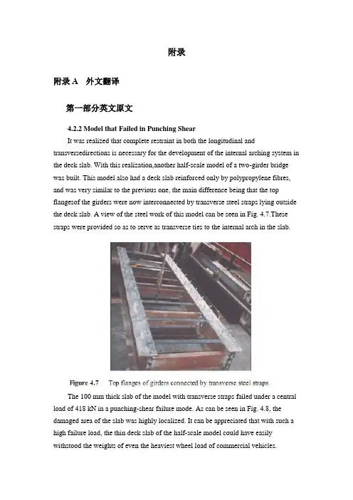
附录附录A 外文翻译第一部分英文原文4.2.2 Model that Failed in Punching ShearIt was realized that complete restraint in both the longitudinal and transversedirections is necessary for the development of the internal arching system in the deck slab. With this realization,another half-scale model of a two-girder bridge was built. This model also had a deck slab reinforced only by polypropylene fibres, and was very similar to the previous one, the main difference being that the top flangesof the girders were now interconnected by transverse steel straps lying outside the deck slab. A view of the steel work of this model can be seen in Fig. 4.7.These straps were provided so as to serve as transverse ties to the internal arch in the slab.The 100 mm thick slab of the model with transverse straps failed under a central load of 418 kN in a punching-shear failure mode. As can be seen in Fig. 4.8, the damaged area of the slab was highly localized. It can be appreciated that with such a high failure load, the thin deck slab of the half-scale model could have easily withstood the weights of even the heaviest wheel load of commercial vehicles.The model tests described above and in sub-section 4.2.1 clearly demonstrate that an internal arching action will indeed develop in a deck slab, but only if it is suitably restrained.4.2.3 Edge StiffeningA further appreciation of the deck slab arching action is provided by tests on a scale model of a skew slab-on-girder bridge. As will be discussed in sub-section 4.4.2, one transverse free edge of the deck slab of this model was stiffened by a composite steel channel with its web in the vertical plane. The other free edge was stiffened by a steel channel diaphragm with its web horizontal and connected to the deck slab through shear connectors. The deck slab near the former transverse edge failed in a mode that was a hybrid between punching shear and flexure. Tests near the composite diaphragm led to failure at a much higher load in punching shear (Bakht and Agarwal, 1993).The above tests confirmed yet again that the presence of the internal arching action in deck slabs induces high in-plane force effects which in turn demand stiffer restraint in the plane of the deck than in the out-of-plane direction.4.3 INTERNALLY RESTRAINED DECK SLABSDeck slabs which require embedded reinforcement for strength will now be referred to as internally restrained deck slabs. The state-of-art up to 1986 relating to the quantification and utilization of the beneficial internal arching action in deck slabs with steel reinforcement has been provided by Bakht and Markovic (1986). Their conclusions complemented with up-to-date information are presented in this chapter in a generally chronological order which, however, cannot be adhered to rigidlybecause of the simultaneous occurrence of some developments.4.3.1 Static Tests on Scale ModelsAbout three decades ago, the Structures Research Office of the Ministry of Transportation of Ontario (MTO), Canada, sponsored an extensive laboratory-based research program into the load carrying capacity of deck slabs; this research program was carried out at Queen's University, Kingston, Ontario. Most of this research was conducted through static tests on scale models of slab-on-girder bridges. This pioneering work is reported by Hewitt and Batchelor (1975) and later by Batchelor et al. (1985), and is summarized in the following.The inability of the concrete to sustain tensile strains, which leads to cracking, has been shown to be the main attribute which causes the compressive membrane forces to develop. This phenomenon is illustrated in Fig. 4.9 (a) which shows the part cross-section of slab-on-girder bridge under the action of a concentrated load.The cracking of the concrete, as shown in the figure, results in a net compressive force near the bottom face of the slab at each of the two girder locations. Midway between the girders, the net compressive force moves towards the top of the slab. It can be readily visualized that the transition of the net compressive force from near the top in the middle region, to near the bottom at the supports corresponds to the familiar arching action. Because of this internal arching action, the failure mode of a deck slab under a concentrated load becomes that of punching shear.If the material of the deck slab has the same stress-strain characteristics in both tension and compression, the slab will not crack and, as shown in Fig. 4.9 (b), will not develop the net compressive force and hence the arching action.In the punching shear type of failure, a frustum separates from the rest of the slab, as shown in schematically in Fig. 4.10. It is noted that in most failure tests, the diameter of the lower end of the frustrum extends to the vicinity of the girders.From analytical and confirmatory laboratory studies, it was established that the most significant factor influencing the failure load of a concrete deck slab is the confinement of the panel under consideration. It was concluded that this confinement is provided by the expanse of the slab beyond the loaded area; its degree was founddifficult to assess analytically. A restraint factor, η, was used as an empirical measure of the confinement; its value is equal to zero for the case of no confinement and 1.0 for full confinement.The effect of various parameters on the failure load can be seen in Table 4.1, which lists the theoretical failure loads for various cases. It can be seen that an increase of the restraint factor from 0.0 to 0.5 results in a very large increase in the failure load. The table also emphasizes the fact that neglect of the restraint factor causes a gross underestimation of the failure load.It was concluded that design for flexure leads to the inclusion of large amounts of unnecessary steel reinforcement in the deck slabs, and that even the minimum amount of steel required for crack control against volumetric changes in concrete is adequate to sustain modern-day, and even future, highway vehicles of North America.It was recommended that for new construction, the reinforcement in a deck slab should be in two layers, with each layer consisting of an orthogonal mesh having the same area of reinforcement in each direction. The area of steel reinforcement in each direction of a mesh was suggested to be 0.2% of the effective area of cross-section of the slab. This empirical method of design was recommended for deck slabs with certain constraints.4.3.2 Pulsating Load Tests on Scale ModelsTo study the fatigue strength of deck slabs with reduced reinforcement, five small scale models with different reinforcement ratios in different panels were tested at the Queen's University at Kingston. Details of this study are reported by Batchelor et al. (1978).Experimental investigation confirmed that for loads normally encountered in North America deck slabs with both conventional and recommended reducedreinforcement have large reserve strengths against failure by fatigue. It was confirmed that the reinforcement in the deck slab should be as noted in sub-section 4.3.1. It is recalled that the 0.2% reinforcement requires that the deck slab must have a minimum restraint factor of 0.5.The work of Okada, et al. (1978) also deals with fatigue tests on full scale models of deck slabs and segments of severely cracked slab removed from eight to ten year old bridges. The application of these test results to deck slabs of actual bridges is open to question because test specimens were removed from the original structures in such a way that they did not retain the confinement necessary for the development of the arching action.4.3.3 Field TestingAlong with the studies described in the preceding sub-section, a program of field testing of the deck slabs of in-service bridges was undertaken by the Structures Research Office of the MTO. The testing consisted of subjecting deck slabs to single concentrated loads, simulating wheel loads, and monitoring the load-deflection characteristics of the slab. The testing is reported by Csagoly et al. (1978) and details of the testing equipment are given by Bakht and Csagoly (1979).Values of the restraint factor, η, were back-calculated from measured deflections.A summary of test results, given in Table 4.2, shows that the average value of η in composite bridges is greater than 0.75, while that for non-composite bridges is 0.42. It was concluded that for new construction, the restraint factor, η, can be assumed to have a minimum value of 0.5.Bakht (1981) reports that after the first application of a test load of high magnitude on deck slabs of existing bridges, a small residual deflection was observed in most cases. Subsequent applications of the same load did not result in further residual deflections. It is postulated that the residual deflections are caused by cracking of the concrete which, as discussed earlier, accompanies the development of the internal arching action. The residual deflections after the first cycle of loading suggest that either the slab was never subjected to loads high enough to cause cracking, or the cracks have 'healed' with time.第二部分汉语翻译4.2.2 在冲切剪应力下的实效模型我们已经知道在桥面板内部拱形系统的形成中,不仅纵向而且横向也被完全约束限制是完全必要的。

本科毕业设计外文翻译混凝土桥梁的结构形式院(系、部)名称:专业名称:学生姓名:学生学号:指导教师:The Structure of Concrete BridgePre-stressed concrete has proved to be technically advantageous, economically competitive, and esthetically superior bridges, from very short span structures using standard components to cable-stayed girders and continuous box girders with clear spans of nearly 100aft .Nearly all concrete bridges, even those of relatively short span, are now pre-stressed. Pre-casting, cast-in-place construction, or a combination of the two methods may be used .Both pre-tensioning and post tensioning are employed, often on the same project.In the United States, highway bridges generally must-meet loading ,design ,and construction requirements of the AASHTO Specification .Design requirements for pedestrian crossings and bridges serving other purposes may be established by local or regional codes and specifications .ACI Code provisions are often incorporated by reference .Bridges spans to about 100ft often consist of pre-cast integral-deck units ,which offer low initial cost ,minimum ,maintenance ,and fast easy construction ,with minimum traffic interruption .Such girders are generally pre-tensioned .The units are placed side by side ,and are often post-tensioned laterally at intermediate diaphragm locations ,after which shear keys between adjacent units are filled with non-shrinking mortar .For highway spans ,an asphalt wearing surface may be applied directly to the top of the pre-cast concrete .In some cases ,a cast-in-place slab is placed to provide composite action .The voided slabs are commonly available in depths from 15 to 21 in .and widths of 3 to 4 ft .For a standard highway HS20 loading, they are suitable for spans to about 50 ft, Standard channel sections are available in depths from 21 to 35 in a variety of widths, and are used for spans between about 20 and 60 ft .The hollow box beams-and single-tee girders are intended for longer spans up to about 100 ft.For medium-span highway bridges ,to about 120 ft ,AASHTO standard I beams are generally used .They are intended for use with a composite cast-in-place roadway slab .Such girders often combine pre-tensioning of the pre-cast member with post-tensioning of the composite beam after the deck is placed .In an effort to obtain improved economy ,some states have adopted more refined designs ,such as the State of Washington standard girders.The specially designed pre-cast girders may be used to carry a monorail transit system .The finished guide way of Walt Disney World Monorail features a series of segments, each consisting of six simply supported pre-tensioned beams ,together to from a continuous structure .Typical spans are 100 to 110 ft . Approximately half of the 337 beams used have some combination of vertical and horizontal curvatures and variable super elevation .Allbeams are hollow, a feature achieved by inserting a styro-foam void in the curved beams and by a moving mandrel in straight beam production.Pre-cast girders may not be used for spans much in excess of 120 ft because of the problems of transporting and erecting large, heavy units.On the other hand ,there is a clear trend toward the use of longer spans for bridges .For elevated urban expressways ,long spans facilitate access and minimize obstruction to activities below .Concern for environmental damage has led to the choice of long spans for continuous viaducts . For river crossings, intermediate piers may be impossible because of requirements of navigational clearance.In typical construction of this type, piers are cast-in-place, often using the slip-forming technique .A “hammerhead” section of box girder is often cast at the top of the pier, and construction proceeds in each direction by the balanced cantilever method. Finally, after the closing cast-in-place joint is made at mid-span, the structure is further post-tensioned for full continuity .Shear keys may be used on the vertical faces between segments, and pre-cast are glued with epoxy resin.The imaginative engineering demonstrated by many special techniques has extended the range of concrete construction for bridges far beyond anything that could be conceived just a few years ago .In the United States, twin curved cast-in –place segmental box girders have recently been completed for of span of 310 ft over the Eel River in northern California .Preliminary design has been completed for twin continuous box girders consisting of central 550 ft spans flanked by 390 ft side spans.Another form of pre-stressed concrete bridge well suited to long spans is the cable-stayed box girder .A notable example is the Chaco-Corrientes Bridge in Argentina .The bridges main span of 804 ft is supported by two A-frame towers, with cable stays stretching from tower tops to points along the deck .The deck itself consists of two parallel box girders made of pre-cast sections erected using the cantilever method .The tensioned cables not only provide a vertical reaction component to support the deck ,but also introduce horizontal compression to the box girders ,adding to the post-tensioning force in those members .Stress-ribbon Bridge pioneered many years ago by the German engineer Ulrich Finsterwalder. The stress-ribbon bridge carries a pipeline and pedestrians over the Rhine River with a span of 446 ft .The superstructure erection sequence was to (a) erect two pairs of cables, (b) place pre-cast slabs forming a sidewalk deck and a U under each of the sets of cables, and (c) cast-in-place concrete within the two Us. The pipeline is placed atop supports at railing height, off to one side, which greatly increases the wind speed of the structure.It is appropriate in discussing bridge forms to mention structural esthetics .The time ispast when structures could be designed on the basis of minimum cost and technical advantages alone .Bridge structures in particular are exposed for all to see .To produce a structure that is visually offensive ,as has occurred all too often in the past, is an act professional irresponsibility .Particularly for major spans ,but also for more ordinary structures ,architectural advice should be sought early in conceptual stage of the design process.混凝土梁桥的结构形式事实证明,预应力混凝土结构是在技术上先进、经济上有竞争力、符合审美学的一种先进技术。

西南交通大学本科毕业设计(论文)外文资料翻译年级:学号:姓名:专业:指导老师:2013年 6 月外文资料原文:13Box girders13.1 GeneralThe box girder is the most flexible bridge deck form。
It can cover a range of spans from25 m up to the largest non—suspended concrete decks built, of the order of 300 m。
Single box girders may also carry decks up to 30 m wide。
For the longer span beams, beyond about 50 m,they are practically the only feasible deck section. For the shorter spans they are in competition with most of the other deck types discussed in this book.The advantages of the box form are principally its high structural efficiency (5.4),which minimises the prestress force required to resist a given bending moment,and its great torsional strength with the capacity this gives to re—centre eccentric live loads,minimising the prestress required to carry them。
The box form lends itself to many of the highly productive methods of bridge construction that have been progressively refined over the last 50 years,such as precast segmental construction with or without epoxy resin in the joints,balanced cantilever erection either cast in—situ or coupled with precast segmental construction, and incremental launching (Chapter 15)。
附录一英文翻译原文AUTOMATIC DEFLECTION AND TEMPERATURE MONITORING OFA BALANCED CANTILEVER CONCRETE BRIDGEby Olivier BURDET, Ph.D.Swiss Federal Institute of Technology, Lausanne, SwitzerlandInstitute of Reinforced and Prestressed Concrete SUMMARYThere is a need for reliable monitoring systems to follow the evolution of the behavior of structures over time.Deflections and rotations are values that reflect the overall structure behavior. This paper presents an innovative approach to the measurement of long-term deformations of bridges by use of inclinometers. High precision electronic inclinometers can be used to follow effectively long-term rotations without disruption of the traffic. In addition to their accuracy, these instruments have proven to be sufficiently stable over time and reliable for field conditions. The Mentue bridges are twin 565 m long box-girder post-tensioned concrete highway bridges under construction in Switzerland. The bridges are built by the balanced cantilever method over a deep valley. The piers are 100 m high and the main span is 150 m. A centralized data acquisition system was installed in one bridge during its construction in 1997. Every minute, the system records the rotation and temperature at a number of measuring points. The simultaneous measurement of rotations and concrete temperature at several locations gives a clear idea of the movements induced by thermal conditions. The system will be used in combination with a hydrostatic leveling setup to follow the long-term behavior of the bridge. Preliminary results show that the system performs reliably and that the accuracy of the sensors is excellent.Comparison of the evolution of rotations and temperature indicate that the structure responds to changes in air temperature rather quickly.1.BACKGROUNDAll over the world, the number of structures in service keeps increasing. With the development of traffic and the increased dependence on reliable transportation, it is becoming more and more necessary to foresee and anticipate the deterioration of structures. In particular,for structures that are part of major transportation systems, rehabilitation works need to be carefully planned in order to minimize disruptions of traffic. Automatic monitoring of structures is thus rapidly developing.Long-term monitoring of bridges is an important part of this overall effort to attempt to minimize both the impact and the cost of maintenance and rehabilitation work of major structures. By knowing the rate of deterioration of a given structure, the engineer is able to anticipate and adequately define the timing of required interventions. Conversely, interventions can be delayed until the condition of the structure requires them, without reducing the overall safety of the structure.The paper presents an innovative approach to the measurement of long-term bridge deformations. The use of high precision inclinometers permits an effective, accurate and unobtrusive following of the long-term rotations. The measurements can be performed under traffic conditions. Simultaneous measurement of the temperature at several locations gives a clear idea of the movements induced by thermal conditions and those induced by creep and shrinkage. The system presented is operational since August 1997 in the Mentue bridge, currently under construction in Switzerland. The structure has a main span of 150 m and piers 100 m high.2. LONG-TERM MONITORING OF BRIDGESAs part of its research and service activities within the Swiss Federal Institute of Technology in Lausanne (EPFL), IBAP - Reinforced and Prestressed Concrete has been involved in the monitoring of long-time deformations of bridges and other structures for over twenty-five years [1, 2, 3, 4]. In the past, IBAP has developed a system for the measurement of long-term deformations using hydrostatic leveling [5, 6]. This system has been in successful service in ten bridges in Switzerland for approximately ten years [5,7]. The system is robust, reliable and sufficiently accurate, but it requires human intervention for each measurement, and is not well suited for automatic data acquisition. One additional disadvantage of this system is that it is only easily applicable to box girder bridges with an accessible box.Occasional continuous measurements over periods of 24 hours have shown that the amplitude of daily movements is significant, usually amounting to several millimeters over a couple of hours. This is exemplified in figure 1, where measurements of the twin Lutrive bridges, taken over a period of several years before and after they were strengthened by post-tensioning, areshown along with measurements performed over a period of 24 hours. The scatter observed in the data is primarily caused by thermal effects on the bridges. In the case of these box-girder bridges built by the balanced cantilever method, with a main span of 143.5 m, the amplitude of deformations on a sunny day is of the same order of magnitude than the long term deformation over several years.Instantaneous measurements, as those made by hydrostatic leveling, are not necessarily representative of the mean position of the bridge. This occurs because the position of the bridge at the time of the measurement is influenced by the temperature history over the past several hours and days. Even if every care was taken to perform the measurements early in the morning and at the same period every year, it took a relatively long time before it was realized that the retrofit performed on the Lutrive bridges in 1988 by additional post-tensioning [3, 7,11] had not had the same effect on both of them.Figure 1: Long-term deflections of the Lutrive bridges, compared to deflections measured in a 24-hour period Automatic data acquisition, allowing frequent measurements to be performed at an acceptable cost, is thus highly desirable. A study of possible solutions including laser-based leveling, fiber optics sensors and GPS-positioning was performed, with the conclusion that, provided that their long-term stability can be demonstrated, current types of electronic inclinometers are suitable for automatic measurements of rotations in existing bridges [8].3. MENTUE BRIDGESThe Mentue bridges are twin box-girder bridges that will carry the future A1 motorway from Lausanne to Bern. Each bridge, similar in design, has an overall length of approximately 565 m, and a width of 13.46 m, designed to carry two lanes of traffic and an emergency lane. The bridges cross a deep valley with steep sides (fig. 2). The balanced cantilever design results from a bridge competition. The 100 m high concrete piers were built using climbing formwork, after which the construction of the balanced cantilever started (fig. 3).4. INCLINOMETERSStarting in 1995, IBAP initiated a research project with the goal of investigating the feasibility of a measurement system using inclinometers. Preliminary results indicated that inclinometers offer several advantages for the automatic monitoring of structures. Table 1 summarizes the main properties of the inclinometers selected for this study.One interesting property of measuring a structure’s rotations, is that, for a given ratio of maximum deflection to span length, the maximum rotation is essentially independent from its static system [8]. Since maximal allowable values of about 1/1,000 for long-term deflections under permanent loads are generally accepted values worldwide, developments made for box-girder bridges with long spans, as is the case for this research, are applicable to other bridges, for instance bridges with shorter spans and other types of cross-sections. This is significant because of the need to monitor smaller spans which constitute the majority of all bridges.The selected inclinometers are of type Wyler Zerotronic ±1°[9]. Their accuracy is 1 microradian (μrad), which corresponds to a rotation of one millimeter per kilometer, a very small value. For an intermediate span of a continuous beam with a constant depth, a mid-span deflection of 1/20,000 would induce a maximum rotation of about 150 μrad, or 0.15 milliradians (mrad).One potential problem with electronic instruments is that their measurements may drift overtime. To quantify and control this problem, a mechanical device was designed allowing the inclinometers to be precisely rotated of 180° in an horizontal plane (fig. 4). The drift of each inclinometer can be very simply obtained by comparing the values obtained in the initial and rotated position with previously obtained values. So far, it has been observed that the type of inclinometer used in this project is not very sensitive to drifting.5. INSTRUMENTATION OF THE MENTUE BRIDGESBecause a number of bridges built by the balanced cantilever method have shown an unsatisfactory behavior in service [2, 7,10], it was decided to carefully monitor the evolution of the deformations of the Mentue bridges. These bridges were designed taking into consideration recent recommendations for the choice of the amount of posttensioning [7,10,13]. Monitoring starting during the construction in 1997 and will be pursued after the bridges are opened to traffic in 2001. Deflection monitoring includes topographic leveling by the highway authorities, an hydrostatic leveling system over the entire length of both bridges and a network of inclinometers in the main span of the North bridge. Data collection iscoordinated by the engineer of record, to facilitate comparison of measured values. The information gained from these observations will be used to further enhance the design criteria for that type of bridge, especially with regard to the amount of post-tensioning [7, 10, 11, 12, 13].The automatic monitoring system is driven by a data acquisition program that gathers and stores the data. This system is able to control various types of sensors simultaneously, at the present time inclinometers and thermal sensors. The computer program driving all the instrumentation offers a flexible framework, allowing the later addition of new sensors or data acquisition systems. The use of the development environment LabView [14] allowed to leverage the large user base in the field of laboratory instrumentation and data analysis. The data acquisition system runs on a rather modest computer, with an Intel 486/66 Mhz processor, 16 MB of memory and a 500 MB hard disk, running Windows NT. All sensor data are gathered once per minute and stored in compressed form on the hard disk. The system is located in the box-girder on top of pier 3 (fig. 5). It can withstand severe weather conditions and will restart itself automatically after a power outage, which happened frequently during construction.6. SENSORSFigure 5(a) shows the location of the inclinometers in the main span of the North bridge. The sensors are placed at the axis of the supports (①an d⑤), at 1/4 and 3/4 (③an d④) of the span and at 1/8 of the span for②. In the cross section, the sensors are located on the North web, at a height corresponding to the center of gravity of the section (fig.5a). The sensors are all connected by a single RS-485 cable to the central data acquisition system located in the vicinity of inclinometer ①. Monitoring of the bridge started already during its construction. Inclinometers①,②and③were installed before the span was completed. The resulting measurement were difficult to interpret, however, because of the wide variations of angles induced by the various stages of this particular method of construction.The deflected shape will be determined by integrating the measured rotations along the length of the bridge (fig.5b). Although this integration is in principle straightforward, it has been shown [8, 16] that the type of loading and possible measurement errors need to be carefully taken into account.Thermal sensors were embedded in concrete so that temperature effects could be taken into account for the adjustment of the geometry of the formwork for subsequent casts. Figure 6 shows the layout of thermal sensors in the main span. The measurement sections are located at the same sections than the inclinometers (fig. 5). All sensors were placed in the formwork before concreting and were operational as soon as the formwork was removed, which was required for the needs of the construction. In each section, seven of the nine thermal sensor (indicated in solid black in fig. 6) are now automatically measured by the central data acquisition system.7. RESULTSFigure 7 shows the results of inclinometry measurements performed from the end ofSeptember to the third week of November 1997. All inclinometers performed well during that period. Occasional interruptions of measurement, as observed for example in early October are due to interruption of power to the system during construction operations. The overall symmetry of results from inclinometers seem to indicate that the instruments drift is not significant for that time period. The maximum amplitude of bridge deflection during the observed period, estimated on the basis of the inclinometers results, is around 40 mm. More accurate values will be computed when the method of determination ofdeflections will have been further calibrated with other measurements. Several periods of increase, respectively decrease, of deflections over several days can be observed in the graph. This further illustrates the need for continuous deformation monitoring to account for such effects. The measurement period was .busy. in terms of construction, and included the following operations: the final concrete pours in that span, horizontal jacking of the bridge to compensate some pier eccentricities, as well as the stressing of the continuity post-tensioning, and the de-tensioning of the guy cables (fig. 3). As a consequence, the interpretation of these measurements is quite difficult. It is expected that further measurements, made after the completion of the bridge, will be simpler to interpret.Figure 8 shows a detail of the measurements made in November, while figure.9 shows temperature measurements at the top and bottom of the section at mid-span made during that same period. It is clear that the measured deflections correspond to changes in the temperature. The temperature at the bottom of the section follows closely variations of the air temperature(measured in the shade near the north web of the girder). On the other hand, the temperature at the top of the cross section is less subject to rapid variations. This may be due to the high elevation of the bridge above ground, and also to the fact that, during the measuring period, there was little direct sunshine on the deck. The temperature gradient between top and bottom of the cross section has a direct relationship with short-term variations. It does not, however, appear to be related to the general tendency to decrease in rotations observed in fig. 8.8. FUTURE DEVELOPMENTSFuture developments will include algorithms to reconstruct deflections from measured rotations. To enhance the accuracy of the reconstruction of deflections, a 3D finite element model of the entire structure is in preparation [15]. This model will be used to identify the influence on rotations of various phenomena, such as creep of the piers and girder, differential settlements, horizontal and vertical temperature gradients or traffic loads.Much work will be devoted to the interpretation of the data gathered in the Mentue bridge. The final part of the research project work will focus on two aspects: understanding the very complex behavior of the structure, and determining the most important parameters, to allow a simple and effective monitoring of the bridges deflections.Finally, the research report will propose guidelines for determination of deflections from measured rotations and practical recommendations for the implementation of measurement systems using inclinometers. It is expected that within the coming year new sites will be equipped with inclinometers. Experiences made by using inclinometers to measure deflections during loading tests [16, 17] have shown that the method is very flexible and competitive with other high-tech methods.As an extension to the current research project, an innovative system for the measurement of bridge joint movement is being developed. This system integrates easily with the existing monitoring system, because it also uses inclinometers, although from a slightly different type.9. CONCLUSIONSAn innovative measurement system for deformations of structures using high precision inclinometers has been developed. This system combines a high accuracy with a relatively simple implementation. Preliminary results are very encouraging and indicate that the use of inclinometers to monitor bridge deformations is a feasible and offers advantages. The system is reliable, does not obstruct construction work or traffic and is very easily installed. Simultaneous temperature measurements have confirmed the importance of temperature variations on the behavior of structural concrete bridges.10. REFERENCES[1] ANDREY D., Maintenance des ouvrages d’art: méthodologie de surveillance, PhD Dissertation Nr 679, EPFL, Lausanne, Switzerland, 1987.[2] BURDET O., Load Testing and Monitoring of Swiss Bridges, CEB Information Bulletin Nr 219, Safety and Performance Concepts, Lausanne, Switzerland, 1993.[3] BURDET O., Critères pour le choix de la quantitéde précontrainte découlant de l.observation de ponts existants, CUST-COS 96, Clermont-Ferrand, France, 1996.[4] HASSAN M., BURDET O., FAVRE R., Combination of Ultrasonic Measurements and Load Tests in Bridge Evaluation, 5th International Conference on Structural Faults and Repair, Edinburgh, Scotland, UK, 1993.[5] FAVRE R., CHARIF H., MARKEY I., Observation à long terme de la déformation des ponts, Mandat de Recherche de l’OFR 86/88, Final Report, EPFL, Lausanne, Switzerland, 1990.[6] FAVRE R., MARKEY I., Long-term Monitoring of Bridge Deformation, NATO Research Workshop, Bridge Evaluation, Repair and Rehabilitation, NATO ASI series E: vol. 187, pp. 85-100, Baltimore, USA, 1990.[7] FAVRE R., BURDET O. et al., Enseignements tirés d’essais de charge et d’observations à long terme pour l’évaluation des ponts et le choix de la précontrainte, OFR Report, 83/90, Zürich, Switzerland, 1995.[8] DAVERIO R., Mesures des déformations des ponts par un système d’inclinométrie,Rapport de maîtrise EPFL-IBAP, Lausanne, Switzerland, 1995.[9] WYLER AG., Technical specifications for Zerotronic Inclinometers, Winterthur, Switzerland, 1996.[10] FAVRE R., MARKEY I., Generalization of the Load Balancing Method, 12th FIP Congress, Prestressed Concrete in Switzerland, pp. 32-37, Washington, USA, 1994.[11] FAVRE R., BURDET O., CHARIF H., Critères pour le choix d’une précontrainte: application au cas d’un renforcement, "Colloque International Gestion des Ouvrages d’Art: Quelle Stratégie pour Maintenir et Adapter le Patrimoine, pp. 197-208, Paris, France, 1994. [12] FAVRE R., BURDET O., Wahl einer geeigneten Vorspannung, Beton- und Stahlbetonbau, Beton- und Stahlbetonbau, 92/3, 67, Germany, 1997.[13] FAVRE R., BURDET O., Choix d’une quantité appropriée de précontrain te, SIA D0 129, Zürich, Switzerland, 1996.[14] NATIONAL INSTRUMENTS, LabView User.s Manual, Austin, USA, 1996.[15] BOUBERGUIG A., ROSSIER S., FAVRE R. et al, Calcul non linéaire du béton arméet précontraint, Revue Français du Génie Civil, vol. 1 n° 3, Hermes, Paris, France, 1997. [16] FEST E., Système de mesure par inclinométrie: développement d’un algorithme de calcul des flèches, Mémoire de maîtrise de DEA, Lausanne / Paris, Switzerland / France, 1997.[17] PERREGAUX N. et al., Vertical Displacement of Bridges using the SOFO System: a Fiber Optic Monitoring Method for Structures, 12th ASCE Engineering Mechanics Conference, San Diego, USA, to be published,1998.译文平衡悬臂施工混凝土桥挠度和温度的自动监测作者Olivier BURDET博士瑞士联邦理工学院,洛桑,瑞士钢筋和预应力混凝土研究所概要:我们想要跟踪结构行为随时间的演化,需要一种可靠的监测系统。
外文资料The Tenth East Asia-Pacific Conference on Structural Engineering and ConstructionAugust 3-5, 2006, Bangkok, ThailandStructural Rehabilitation of Concrete Bridges with CFRPComposites-Practical Details and ApplicationsRiyad S. ABOUTAHA1, and Nuttawat CHUTARAT2 ABSTRACT: Many old existing bridges are still active in the various highway transportation networks, carrying heavier and faster trucks, in all kinds of environments. Water, salt, and wind have caused damage to these old bridges, and scarcity of maintenance funds has aggravated their conditions. One attempt to restore the original condition; and to extend the service life of concrete bridges is by the use of carbon fiber reinforced polymer (CFRP) composites. There appear to be very limited guides on repair of deteriorated concrete bridges with CFRP composites. In this paper, guidelines for nondestructive evaluation (NDE), nondestructive testing (NDT), and rehabilitation of deteriorated concrete bridges with CFRP composites are presented. The effect of detailing on ductility and behavior of CFRP strengthened concrete bridges are also discussed and presented.KEYWORDS: Concrete deterioration, corrosion of steel, bridge rehabilitation, CFRP composites.1 IntroductionThere are several destructive external environmental factors that limit the service life of bridges. These factors include but not limited to chemical attacks, corrosion of reinforcing steel bars, carbonation of concrete, and chemical reaction of aggregate. If bridges were not well maintained, these factors may lead to a structural deficiency, which reduces the margin of safety, and may result in structural failure. In order to rehabilitate and/or strengthen deteriorated existing bridges, thorough evaluation should be conducted. The purpose of the evaluation is to assess the actual condition of any existing bridge, and generally to examine the remaining strength and load carry capacity of the bridge.1 Associate Professor, Syracuse University, U.S.A.2 Lecturer, Sripatum University, Thailand.One attempt to restore the original condition, and to extend the service life of concrete bridges is by the use of carbon fiber reinforced polymer (CFRP) composites.In North America, Europe and Japan, CFRP has been extensively investigated and applied. Several design guides have been developed for strengthening of concrete bridges with CFRP composites. However, there appear to be very limited guides on repair of deteriorated concrete bridges with CFRP composites. This paper presents guidelines for repair of deteriorated concrete bridges, along with proper detailing. Evaluation, nondestructive testing, and rehabilitation of deteriorated concrete bridges with CFRP composites are presented. Successful application of CFRP composites requires good detailing as the forces developed in the CFRP sheets are transferred by bond at the concrete-CFRP interface. The effect of detailing on ductility and behavior of CFRP strengthened concrete bridges will also be discussed and presented.2 Deteriorated Concrete BridgesDurability of bridges is of major concern. Increasing number of bridges are experiencing significant amounts of deterioration prior to reaching their design service life. This premature deterioration considered a problem in terms of the structural integrity and safety of the bridge. In addition, deterioration of a bridge has a considerable magnitude of costs associated with it. In many cases, the root of a deterioration problem is caused by corrosion of steel reinforcement in concrete structures. Concrete normally acts to provide a high degree of protection against corrosion of the embedded reinforcement. However, corrosion will result in those cases that typically experience poor concrete quality, inadequate design or construction, and harsh environmental conditions. If not treated a durability problem, e.g. corrosion, may turn into a strength problem leading to a structural deficiency, as shown in Figure1.Figure1 Corrosion of the steel bars is leading to a structural deficiency3 Non-destructive Testing of Deteriorated Concrete Bridge PiersIn order to design a successful retrofit system, the condition of the existing bridge should be thoroughly evaluated. Evaluation of existing bridge elements or systems involves review of the asbuilt drawings, as well as accurate estimate of the condition of the existing bridge, as shown in Figure2. Depending on the purpose of evaluation, non-destructive tests may involve estimation of strength, salt contents, corrosion rates, alkalinity in concrete, etc.Figure2 Visible concrete distress marked on an elevation of a concrete bridge pier Although most of the non-destructive tests do not cause any damage to existing bridges, some NDT may cause minor local damage (e.g. drilled holes & coring) that should be repaired right after the NDT. These tests are also referred to as partial destructive tests but fall under non-destructive testing.In order to select the most appropriate non-destructive test for a particular case, thepurpose of the test should be identified. In general, there are three types of NDT to investigate: (1) strength, (2) other structural properties, and (3) quality and durability. The strength methods may include; compressive test (e.g. core test/rebound hammer/ ultrasonic pulse velocity), surface hardness test (e.g. rebound hammer), penetration test (e.g. Windsor probe), and pullout test (anchor test).Other structural test methods may include; concrete cover thickness (cover-meter), locating rebars (rebar locator), rebar size (some rebar locators/rebar data scan), concrete moisture (acquameter/moisture meter), cracking (visual test/impact echo/ultrasonic pulse velocity), delamination (hammer test/ ultrasonic pulse velocity/impact echo), flaws and internal cracking (ultrasonic pulse velocity/impact echo), dynamic modulus of elasticity (ultrasonic pulse velocity), Possion’s ratio (ultrasonic pulse velocity), thickness of concrete slab or wall (ultrasonic pulse velocity), CFRP debonding (hammer test/infrared thermographic technique), and stain on concrete surface (visual inspection).Quality and durability test methods may include; rebar corrosion rate –field test, chloride profile field test, rebar corrosion analysis, rebar resistivity test, alkali-silica reactivity field test, concrete alkalinity test (carbonation field test), concrete permeability (field test for permeability).4 Non-destructive Evaluation of Deteriorated Concrete Bridge PiersThe process of evaluating the structural condition of an existing concrete bridge consists of collecting information, e.g. drawings and construction & inspection records, analyzing NDT data, and structural analysis of the bridge. The evaluation process can be summarized as follows: (1) Planning for the assessment, (2) Preliminary assessment, which involves examination of available documents, site inspection, materials assessment, and preliminary analysis, (3) Preliminary evaluation, this involves: examination phase, and judgmental phase, and finally (4) the cost-impact study.If the information is insufficient to conduct evaluation to a specific required level, then a detailed evaluation may be conducted following similar steps for the above-mentioned preliminary assessment, but in-depth assessment. Successful analytical evaluation of an existing deteriorated concrete bridge should consider the actual condition of the bridge and level of deterioration of various elements. Factors, e.g. actual concrete strength, level of damage/deterioration, actual size of corroded rebars, loss of bond between steel and concrete, etc. should be modeled into a detailed analysis. If such detailed analysis is difficult to accomplish within a reasonable period of time, thenevaluation by field load testing of the actual bridge in question may be required.5 Bridge Rehabilitation with CFRP CompositesApplication of CFRP composite materials is becoming increasingly attractive to extend the service life of existing concrete bridges. The technology of strengthening existing bridges with externally bonded CFRP composites was developed primarily in Japan (FRP sheets), and Europe (laminates). The use of these materials for strengthening existing concrete bridges started in the 1980s, first as a substitute to bonded steel plates, and then as a substitute for steel jackets for seismic retrofit of bridge columns. CFRP Composite materials are composed of fiber reinforcement bonded together with a resin matrix. The fibers provide the composite with its unique structural properties. The resin matrix supports the fibers, protect them, and transfer the applied load to the fibers through shearing stresses. Most of the commercially available CFRP systems in the construction market consist of uniaxial fibers embedded in a resin matrix, typically epoxy. Carbon fibers have limited ultimate strain, which may limit the deformability of strengthened members. However, under traffic loads, local debonding between FRP sheets and concrete substrate would allow for acceptable level of global deformations before failure.CFRP composites could be used to increase the flexural and shear strength of bridge girders including pier cap beams, as shown in Figure3. In order to increase the ductility of CFRP strengthened concrete girders, the longitudinal CFRP composite sheets used for flexural strengthening should be anchored with transverse/diagonal CFRP anchors to prevent premature delamination of the longitudinal sheets due to localized debonding at the concrete surface-CFRP sheet interface. In order to prevent stress concentration and premature fracture of the CFRP sheets at the corners of concrete members, the corners should be rounded at 50mm (2.0 inch) radius, as shown in Figure3.Deterioration of concrete bridge members due to corrosion of steel bars usually leads in loss of steel section and delamination of concrete cover. As a result, such deterioration may lead to structural deficiency that requires immediate attention. Figure4 shows rehabilitation of structurally deficient concrete bridge pier using CFRP composites.Figure3 Flexural and shear strengthening of concrete bridge pier with FRP compositesFigure4 Rehabilitation of deteriorated concrete bridge pier with CFRP composites6 Summary and ConclusionsEvaluation, non-destructive testing and rehabilitation of deteriorated concrete bridges were presented. Deterioration of concrete bridge components due to corrosion may lead to structural deficiencies, e.g. flexural and/or shear failures. Application of CFRP composite materials is becoming increasingly attractive solution to extend the service life of existing concrete bridges. CFRP composites could be utilized for flexural and shear strengthening, as well as for restoration of deteriorated concrete bridge components. The CFRP composite sheets should be well detailed to prevent stress concentration and premature fracture or delamination. For successful rehabilitation of concrete bridges in corrosive environments, a corrosion protection system should be used along with the CFRP system.第十届东亚太结构工程设计与施工会议2006年8月3-5号,曼谷,泰国碳纤维复合材料修复混凝土桥梁结构的详述及应用Riyad S. ABOUTAHA1, and Nuttawat CHUTARAT2摘要:在各式各样的公路交通网络中,许多现有的古老桥梁,在各种恶劣的环境下,如更重的荷载和更快的车辆等条件下,依然在被使用着。
桥梁工程毕业论文英文Title: Analysis and Design of Bridge StructuresAbstract:Bridge engineering is an integral part of civil engineering and plays a crucial role in connecting communities and facilitating transportation. The purpose of this thesis is to analyze and design bridge structures, focusing on key components such as foundations, superstructures, and substructures. The analysis includes evaluating the structural behavior and load carrying capacity through the utilization of various analytical tools. Furthermore, the design phase encompasses selecting suitable materials and designing components to meet safety and durability requirements. The study serves as a comprehensive guide to understanding the principles and processes involved in bridge engineering.1. IntroductionBridges are vital infrastructure that connects people, places, and economies. The study of bridge engineering involves the application of core principles like physics, materials science, and mathematics todesign and construct safe and efficient bridge structures. This thesis aims to provide an overview of the analysis and design principles involved in bridge engineering.2. Structural AnalysisThe analysis of bridge structures is crucial to ensure their safety and functionality. This chapter presents various analytical techniques for evaluating bridge behavior. The use of finite element analysis, structural modeling, and computer-aided design software is discussed in detail. Different load types and load combinations are also considered to determine the resilience and load carrying capacity of the bridge.3. Foundation DesignThe foundation is a critical component of any bridge structure, as it transfers the loads from the superstructure to the underlying ground. This chapter explores various foundation types, such as shallow foundations, deep foundations, and pile foundations. Design considerations, including soil mechanics, bearing capacity, settlement analysis, and groundwater conditions, are discussed. The use ofgeotechnical engineering software to simulate and optimize foundation design is also explored.4. Superstructure DesignThe superstructure refers to the portion of the bridge that supports the traffic loads and transfers them to the substructure. This chapter discusses the different types of superstructures, including beam bridges, truss bridges, and arch bridges. The selection of materials, such as concrete, steel, and composite materials, is analyzed based on their structural properties and cost-effectiveness. The design process incorporates the calculation of load distribution, structural stability, and deflection limits.5. Substructure DesignThe substructure comprises the bridge piers, abutments, and retaining walls, which provide support to the superstructure. This chapter focuses on the design considerations for substructures, including the selection of suitable materials, analysis of load distribution, and evaluation of stability against various forces and environmental conditions. Design principles for reinforced concrete and masonry substructures are explored, along with mitigationstrategies for potential issues such as scour and seismic activity.6. Safety and DurabilityEnsuring safety and durability is of utmost importance in bridge engineering. This chapter discusses the necessary steps for evaluating the safety of bridge structures, including factor of safety calculations, failure mode analysis, and risk assessment procedures. The discussion also includes guidelines for maintenance and inspection to ensure long-term performance and durability.7. ConclusionThis thesis provides an in-depth analysis and design framework for bridge structures. By comprehensively exploring the key components of bridges, including foundations, superstructures, and substructures, it provides valuable insights into the principles and processes involved in bridge engineering. The knowledge gained from this study will contribute to the safe and efficient design and construction of future bridge projects.。

中英文对照外文翻译(文档含英文原文和中文翻译)Bridge research in EuropeA brief outline is given of the development of the European Union, together with the research platform in Europe. The special case of post-tensioned bridges in the UK is discussed. In order to illustrate the type of European research being undertaken, an example is given from the University of Edinburgh portfolio: relating to the identification of voids in post-tensioned concrete bridges using digital impulse radar.IntroductionThe challenge in any research arena is to harness the findings of different research groups to identify a coherent mass of data, which enables research and practice to be better focused. A particular challenge exists with respect to Europe where language barriers are inevitably very significant. The European Community was formed in the 1960s based upon a political will within continental Europe to avoid the European civil wars, which developed into World War 2 from 1939 to 1945. The strong political motivation formed the original community of which Britain was not a member. Many of the continental countries saw Britain’s interest as being purelyeconomic. The 1970s saw Britain joining what was then the European Economic Community (EEC) and the 1990s has seen the widening of the community to a European Union, EU, with certain political goals together with the objective of a common European currency.Notwithstanding these financial and political developments, civil engineering and bridge engineering in particular have found great difficulty in forming any kind of common thread. Indeed the educational systems for University training are quite different between Britain and the European continental countries. The formation of the EU funding schemes —e.g. Socrates, Brite Euram and other programs have helped significantly. The Socrates scheme is based upon the exchange of students between Universities in different member states. The Brite Euram scheme has involved technical research grants given to consortia of academics and industrial partners within a number of the states— a Brite Euram bid would normally be led by an industrialist.In terms of dissemination of knowledge, two quite different strands appear to have emerged. The UK and the USA have concentrated primarily upon disseminating basic research in refereed journal publications: ASCE, ICE and other journals. Whereas the continental Europeans have frequently disseminated basic research at conferences where the circulation of the proceedings is restricted.Additionally, language barriers have proved to be very difficult to break down. In countries where English is a strong second language there has been enthusiastic participation in international conferences based within continental Europe —e.g. Germany, Italy, Belgium, The Netherlands and Switzerland. However, countries where English is not a strong second language have been hesitant participants }—e.g. France.European researchExamples of research relating to bridges in Europe can be divided into three types of structure:Masonry arch bridgesBritain has the largest stock of masonry arch bridges. In certain regions of the UK up to 60% of the road bridges are historic stone masonry arch bridges originally constructed for horse drawn traffic. This is less common in other parts of Europe as many of these bridges were destroyed during World War 2.Concrete bridgesA large stock of concrete bridges was constructed during the 1950s, 1960s and 1970s. At the time, these structures were seen as maintenance free. Europe also has a large number of post-tensioned concrete bridges with steel tendon ducts preventing radar inspection. This is a particular problem in France and the UK.Steel bridgesSteel bridges went out of fashion in the UK due to their need for maintenance as perceived in the 1960s and 1970s. However, they have been used for long span and rail bridges, and they are now returning to fashion for motorway widening schemes in the UK.Research activity in EuropeIt gives an indication certain areas of expertise and work being undertaken in Europe, but is by no means exhaustive.In order to illustrate the type of European research being undertaken, an example is given from the University of Edinburgh portfolio. The example relates to the identification of voids in post-tensioned concrete bridges, using digital impulse radar.Post-tensioned concrete rail bridge analysisOve Arup and Partners carried out an inspection and assessment of the superstructure of a 160 m long post-tensioned, segmental railway bridge in Manchester to determine its load-carrying capacity prior to a transfer of ownership, for use in the Metrolink light rail system..Particular attention was paid to the integrity of its post-tensioned steel elements. Physical inspection, non-destructive radar testing and other exploratory methods were used to investigate for possible weaknesses in the bridge.Since the sudden collapse of Ynys-y-Gwas Bridge in Wales, UK in 1985, there has been concern about the long-term integrity of segmental, post-tensioned concrete bridges which may b e prone to ‘brittle’ failure without warning. The corrosion protection of the post-tensioned steel cables, where they pass through joints between the segments, has been identified as a major factor affecting the long-term durability and consequent strength of this type of bridge. The identification of voids in grouted tendon ducts at vulnerable positions is recognized as an important step in the detection of such corrosion.Description of bridgeGeneral arrangementBesses o’ th’ Barn Bridge is a 160 m long, three span, segmental, post-tensionedconcrete railway bridge built in 1969. The main span of 90 m crosses over both the M62 motorway and A665 Bury to Prestwick Road. Minimum headroom is 5.18 m from the A665 and the M62 is cleared by approx 12.5 m.The superstructure consists of a central hollow trapezoidal concrete box section 6.7 m high and 4 m wide. The majority of the south and central spans are constructed using 1.27 m long pre-cast concrete trapezoidal box units, post-tensioned together. This box section supports the in site concrete transverse cantilever slabs at bottom flange level, which carry the rail tracks and ballast.The center and south span sections are of post-tensioned construction. These post-tensioned sections have five types of pre-stressing:1. Longitudinal tendons in grouted ducts within the top and bottom flanges.2. Longitudinal internal draped tendons located alongside the webs. These are deflected at internal diaphragm positions and are encased in in site concrete.3. Longitudinal macalloy bars in the transverse cantilever slabs in the central span .4. Vertical macalloy bars in the 229 mm wide webs to enhance shear capacity.5. Transverse macalloy bars through the bottom flange to support the transverse cantilever slabs.Segmental constructionThe pre-cast segmental system of construction used for the south and center span sections was an alternative method proposed by the contractor. Current thinking suggests that such a form of construction can lead to ‘brittle’ failure of the ent ire structure without warning due to corrosion of tendons across a construction joint,The original design concept had been for in site concrete construction.Inspection and assessmentInspectionInspection work was undertaken in a number of phases and was linked with the testing required for the structure. The initial inspections recorded a number of visible problems including:Defective waterproofing on the exposed surface of the top flange.Water trapped in the internal space of the hollow box with depths up to 300 mm.Various drainage problems at joints and abutments.Longitudinal cracking of the exposed soffit of the central span.Longitudinal cracking on sides of the top flange of the pre-stressed sections.Widespread sapling on some in site concrete surfaces with exposed rusting reinforcement.AssessmentThe subject of an earlier paper, the objectives of the assessment were:Estimate the present load-carrying capacity.Identify any structural deficiencies in the original design.Determine reasons for existing problems identified by the inspection.Conclusion to the inspection and assessmentFollowing the inspection and the analytical assessment one major element of doubt still existed. This concerned the condition of the embedded pre-stressing wires, strands, cables or bars. For the purpose of structural analysis these elements、had been assumed to be sound. However, due to the very high forces involved,、a risk to the structure, caused by corrosion to these primary elements, was identified.The initial recommendations which completed the first phase of the assessment were:1. Carry out detailed material testing to determine the condition of hidden structural elements, in particularthe grouted post-tensioned steel cables.2. Conduct concrete durability tests.3. Undertake repairs to defective waterproofing and surface defects in concrete.Testing proceduresNon-destructi v e radar testingDuring the first phase investigation at a joint between pre-cast deck segments the observation of a void in a post-tensioned cable duct gave rise to serious concern about corrosion and the integrity of the pre-stress. However, the extent of this problem was extremely difficult to determine. The bridge contains 93 joints with an average of 24 cables passing through each joint, i.e. there were approx. 2200 positions where investigations could be carried out. A typical section through such a joint is that the 24 draped tendons within the spine did not give rise to concern because these were protected by in site concrete poured without joints after the cables had been stressed.As it was clearly impractical to consider physically exposing all tendon/joint intersections, radar was used to investigate a large numbers of tendons and hence locate duct voids within a modest timescale. It was fortunate that the corrugated steel ducts around the tendons were discontinuous through the joints which allowed theradar to detect the tendons and voids. The problem, however, was still highly complex due to the high density of other steel elements which could interfere with the radar signals and the fact that the area of interest was at most 102 mm wide and embedded between 150 mm and 800 mm deep in thick concrete slabs.Trial radar investigations.Three companies were invited to visit the bridge and conduct a trial investigation. One company decided not to proceed. The remaining two were given 2 weeks to mobilize, test and report. Their results were then compared with physical explorations.To make the comparisons, observation holes were drilled vertically downwards into the ducts at a selection of 10 locations which included several where voids were predicted and several where the ducts were predicted to be fully grouted. A 25-mm diameter hole was required in order to facilitate use of the chosen horoscope. The results from the University of Edinburgh yielded an accuracy of around 60%.Main radar sur v ey, horoscope verification of v oids.Having completed a radar survey of the total structure, a baroscopic was then used to investigate all predicted voids and in more than 60% of cases this gave a clear confirmation of the radar findings. In several other cases some evidence of honeycombing in the in site stitch concrete above the duct was found.When viewing voids through the baroscopic, however, it proved impossible to determine their actual size or how far they extended along the tendon ducts although they only appeared to occupy less than the top 25% of the duct diameter. Most of these voids, in fact, were smaller than the diameter of the flexible baroscopic being used (approximately 9 mm) and were seen between the horizontal top surface of the grout and the curved upper limit of the duct. In a very few cases the tops of the pre-stressing strands were visible above the grout but no sign of any trapped water was seen. It was not possible, using the baroscopic, to see whether those cables were corroded.Digital radar testingThe test method involved exciting the joints using radio frequency radar antenna: 1 GHz, 900 MHz and 500 MHz. The highest frequency gives the highest resolution but has shallow depth penetration in the concrete. The lowest frequency gives the greatest depth penetration but yields lower resolution.The data collected on the radar sweeps were recorded on a GSSI SIR System 10.This system involves radar pulsing and recording. The data from the antenna is transformed from an analogue signal to a digital signal using a 16-bit analogue digital converter giving a very high resolution for subsequent data processing. The data is displayed on site on a high-resolution color monitor. Following visual inspection it is then stored digitally on a 2.3-gigabyte tape for subsequent analysis and signal processing. The tape first of all records a ‘header’ noting the digital radar settings together with the trace number prior to recording the actual data. When the data is played back, one is able to clearly identify all the relevant settings —making for accurate and reliable data reproduction.At particular locations along the traces, the trace was marked using a marker switch on the recording unit or the antenna.All the digital records were subsequently downloaded at the University’s NDT laboratory on to a micro-computer.(The raw data prior to processing consumed 35 megabytes of digital data.)Post-processing was undertaken using sophisticated signal processing software. Techniques available for the analysis include changing the color transform and changing the scales from linear to a skewed distribution in order to highlight、突出certain features. Also, the color transforms could be changed to highlight phase changes. In addition to these color transform facilities, sophisticated horizontal and vertical filtering procedures are available. Using a large screen monitor it is possible to display in split screens the raw data and the transformed processed data. Thus one is able to get an accurate indication of the processing which has taken place. The computer screen displays the time domain calibrations of the reflected signals on the vertical axis.A further facility of the software was the ability to display the individual radar pulses as time domain wiggle plots. This was a particularly valuable feature when looking at individual records in the vicinity of the tendons.Interpretation of findingsA full analysis of findings is given elsewhere, Essentially the digitized radar plots were transformed to color line scans and where double phase shifts were identified in the joints, then voiding was diagnosed.Conclusions1. An outline of the bridge research platform in Europe is given.2. The use of impulse radar has contributed considerably to the level of confidence in the assessment of the Besses o’ th’ Barn Rail Bridge.3. The radar investigations revealed extensive voiding within the post-tensioned cable ducts. However, no sign of corrosion on the stressing wires had been found except for the very first investigation.欧洲桥梁研究欧洲联盟共同的研究平台诞生于欧洲联盟。

外文文献翻译BRIDGE ENGINEERING AND AESTHETICSEvolvement of bridge Engineering,brief reviewAmong the early documented reviews of construction materials and structure types are the books of Marcus Vitruvios Pollio in the first century B.C.The basic principles of statics were developed by the Greeks , and were exemplified in works and applications by Leonardo da Vinci,Cardeno,and Galileo.In the fifteenth and sixteenth century, engineers seemed to be unaware of this record , and relied solely on experience and tradition for building bridges and aqueducts .The state of the art changed rapidly toward the end of the seventeenth century when Leibnitz, Newton, and Bernoulli introduced mathematical formulations. Published works by Lahire (1695)and Belidor (1792) about the theoretical analysis of structures provided the basis in the field of mechanics of materials .Kuzmanovic(1977) focuses on stone and wood as the first bridge-building materials. Iron was introduced during the transitional period from wood to steel .According to recent records , concrete was used in France as early as 1840 for a bridge 39 feet (12 m) long to span the Garoyne Canal at Grisoles, but reinforced concrete was not introduced in bridge construction until the beginning of this century . Prestressed concrete was first used in 1927.Stone bridges of the arch type (integrated superstructure and substructure) were constructed in Rome and other European cities in the middle ages . These arches were half-circular , with flat arches beginning to dominate bridge work during the Renaissance period. This concept was markedly improved at the end of the eighteenth century and found structurally adequate to accommodate future railroad loads . In terms of analysis and use of materials , stone bridges have not changed much ,but the theoretical treatment was improved by introducing the pressure-line concept in the early 1670s(Lahire, 1695) . The arch theory was documented in model tests where typical failure modes were considered (Frezier,1739).Culmann(1851) introduced the elastic center method for fixed-end arches, and showed that three redundant parameters can be found by the use of three equations of coMPatibility.Wooden trusses were used in bridges during the sixteenth century when Palladio built triangular frames for bridge spans 10 feet long . This effort also focused on the three basic principles og bridge design : convenience(serviceability) ,appearance , and endurance(strength) . several timber truss bridges were constructed in western Europe beginning in the 1750s with spans up to 200 feet (61m) supported on stone substructures .Significant progress was possible in the United States and Russia during the nineteenth century ,prompted by the need to cross major rivers and by an abundance of suitable timber . Favorable economic considerations included initial low cost and fast construction .The transition from wooden bridges to steel types probably did not begin until about 1840 ,although the first documented use of iron in bridges was the chain bridge built in 1734 across the Oder River in Prussia . The first truss completely made of iron was in 1840 in the United States , followed by England in 1845 , Germany in 1853 , and Russia in 1857 . In 1840 , the first iron arch truss bridge was built across the Erie Canal at Utica .The Impetus of AnalysisThe theory of structuresThe theory of structures ,developed mainly in the ninetheenth century,focused on truss analysis, with the first book on bridges written in 1811. The Warren triangular truss was introduced in 1846 ,supplemented by a method for calculating the correcet forces .I-beams fabricated from plates became popular in England and were used in short-span bridges.In 1866, Culmann explained the principles of cantilever truss bridges, and one year later the first cantilever bridge was built across the Main River in Hassfurt, Germany, with a center span of 425 feet (130m) . The first cantilever bridge in the United States was built in 1875 across the Kentucky River.A most impressive railway cantilever bridge in the nineteenth century was the First of Forth bridge , built between 1883 and 1893 , with span magnitudes of 1711 feet (521.5m). At about the same time , structural steel was introduced as a prime material in bridge work , although its quality was often poor . Several early examples are the Eads bridge in St.Louis ; the Brooklyn bridge in New York ; and the Glasgow bridge in Missouri , all completed between 1874 and 1883.Among the analytical and design progress to be mentioned are the contributions of Maxwell , particularly for certain statically indeterminate trusses ; the books by Cremona (1872) on graphical statics; the force method redefined by Mohr; and the works by Clapeyron who introduced the three-moment equations.The Impetus of New MaterialsSince the beginning of the twentieth century , concrete has taken its place as one of the most useful and important structural materials . Because of the coMParative ease with which it can be molded into any desired shape , its structural uses are almost unlimited . Wherever Portland cement and suitable aggregates are available , it can replace other materials for certain types of structures, such as bridge substructure and foundation elements .In addition , the introduction of reinforced concrete in multispan frames at the beginning of this century imposed new analytical requirements . Structures of a high order of redundancy could not be analyzed with the classical methods of the nineteenth century .The importance of joint rotation was already demonstrated by Manderla (1880) and Bendixen (1914) , who developed relationships between joint moments and angular rotations from which the unknown moments can be obtained ,the so called slope-deflection method .More simplifications in frame analysis were made possible by the work of Calisev (1923) , who used successive approximations to reduce the system of equations to one simple expression for each iteration step . This approach was further refined and integrated by Cross (1930) in what is known as the method of moment distribution .One of the most import important recent developments in the area of analytical procedures is the extension of design to cover the elastic-plastic range , also known as load factor or ultimate design. Plastic analysis was introduced with some practical observations by Tresca (1846) ; and was formulated by Saint-Venant (1870) , The concept of plasticity attracted researchers and engineers after World War Ⅰ, mainly in Germany , with the center of activity shifting to England and the United States after World War Ⅱ.The probabilistic approach is a new design concept that is expected to replace the classical deterministic methodology.A main step forward was the 1969 addition of the Federal Highway Adiministration (FHWA)”Criteria for Reinforced Concrete Bridge Members “ that covers strength and serviceability at ultimate design . This was prepared for use in conjunction with the 1969 American Association of State Highway Offficials (AASHO) Standard Specification, and was presented in a format that is readily adaptable to the development of ultimate design specifications .According to this document , the proportioning of reinforced concrete members ( including columns ) may be limited by various stages of behavior : elastic , cracked , andultimate . Design axial loads , or design shears . Structural capacity is the reaction phase , and all calculated modified strength values derived from theoretical strengths are the capacity values , such as moment capacity ,axial load capacity ,or shear capacity .At serviceability states , investigations may also be necessary for deflections , maximum crack width , and fatigue . Bridge TypesA notable bridge type is the suspension bridge , with the first example built in the United States in 1796. Problems of dynamic stability were investigated after the Tacoma bridge collapse , and this work led to significant theoretical contributions Steinman ( 1929 ) summarizes about 250 suspension bridges built throughout the world between 1741 and 1928 .With the introduction of the interstate system and the need to provide structures at grade separations , certain bridge types have taken a strong place in bridge practice. These include concrete superstructures (slab ,T-beams,concrete box girders ), steel beam and plate girders , steel box girders , composite construction , orthotropic plates , segmental construction , curved girders ,and cable-stayed bridges . Prefabricated members are given serious consideration , while interest in box sections remains strong .Bridge Appearance and AestheticsGrimm ( 1975 ) documents the first recorded legislative effort to control the appearance of the built environment . This occurred in 1647 when the Council of New Amsterdam appointed three officials . In 1954 , the Supreme Court of the United States held that it is within the power of the legislature to determine that communities should be attractive as well as healthy , spacious as well as clean , and balanced as well as patrolled . The Environmental Policy Act of 1969 directs all agencies of the federal government to identify and develop methods and procedures to ensure that presently unquantified environmental amentities and values are given appropriate consideration in decision making along with economic and technical aspects .Although in many civil engineering works aesthetics has been practiced almost intuitively , particularly in the past , bridge engineers have not ignored or neglected the aesthetic disciplines .Recent research on the subject appears to lead to a rationalized aesthetic design methodology (Grimm and Preiser , 1976 ) .Work has been done on the aesthetics of color ,light ,texture , shape , and proportions , as well as other perceptual modalities , and this direction is both theoretically and empirically oriented .Aesthetic control mechanisms are commonly integrated into the land-use regulations and design standards . In addition to concern for aesthetics at the state level , federal concern focuses also on the effects of man-constructed environment on human life , with guidelines and criteria directed toward improving quality and appearance in the design process . Good potential for the upgrading of aesthetic quality in bridge superstructures and substructures can be seen in the evaluation structure types aimed at improving overall appearance .LOADS AND LOADING GROUPSThe loads to be considered in the design of substructures and bridge foundations include loads and forces transmitted from the superstructure, and those acting directly on the substructure and foundation .AASHTO loads . Section 3 of AASHTO specifications summarizes the loads and forces to be considered in the design of bridges (superstructure and substructure ) . Briefly , these are dead load ,live load , iMPact or dynamic effect of live load , wind load , and other forces such as longitudinal forces , centrifugal force ,thermal forces , earth pressure , buoyancy , shrinkage andlong term creep , rib shortening , erection stresses , ice and current pressure , collision force , and earthquake stresses .Besides these conventional loads that are generally quantified , AASHTO also recognizes indirect load effects such as friction at expansion bearings and stresses associated with differential settlement of bridge components .The LRFD specifications divide loads into two distinct categories : permanent and transient .Permanent loadsDead Load : this includes the weight DC of all bridge components , appurtenances and utilities, wearing surface DW and future overlays , and earth fill EV. Both AASHTO and LRFD specifications give tables summarizing the unit weights of materials commonly used in bridge work .Transient LoadsVehicular Live Load (LL)Vehicle loading for short-span bridges :considerable effort has been made in the United States and Canada to develop a live load model that can represent the highway loading more realistically than the H or the HS AASHTO models . The current AASHTO model is still the applicable loading.桥梁工程和桥梁美学桥梁工程的发展概况早在公元前1世纪,Marcus Vitrucios Pollio 的著作中就有关于建筑材料和结构类型的记载和评述。

Long and light——《Bridge design & engineering》Closure of the main span on the Sundoya Bridge in Norway is expected to take place in the first week after Easter. This graceful crossing, the second longest of its type in the world, is being built in situ using high performance concreteSundoya Bridge is situated in one of Norway's most scenic areas, only 100km south of the Arctic Circle. The 538m-long bridge spans Sundet, and when it is complete will provide a ferry-free road connection between Sundoya and the mainland. It is located some 35km west of the city of Mosjoen, close to highway 78 between Mosjoen and Sandnessjoen.It will be the second large bridge project connecting Alstenoya to the mainland, coming more than 12 years after the Helgeland Bridge was opened. The region is no stranger to world-record scale bridges ?the Helgeland Bridge's 425m long main span was the longest cable-stayed span in the world when it opened in 1992.Sundoya Bridge is divided into three spans; it has a main span of 298m and two side spans of 120m. The main span will be the second longest span in the world for a continuous post-tensioned cast in place box section concrete bridge.In terms of its design, consultant Dr Ing Aas-Jakobsen has followed a similar approach to that taken for the Raftsundet Bridge, opened in 1998, to which the Sundoya Bridge will almost be a twin. The two bridges have identical main spans, but Raftsundet has four spans as opposed to Sundoya's three. Contractor AS Anlegg, which is part of the joint venture building Sundoya, was also the contractor on the Raftsundet Bridge, and architect Boarch Arkitekter has also worked on the two schemes.In January 2001 the joint venture company AF Sundoybrua won the contract from client Statens Vegvesen to build the Sundoya Bridge. This joint venture consisted of the contractors Reinertsen Anlegg and NCC Construction.High performance concrete is central to the design of the bridge ?both normal weight HPC and lightweight HPC. Normal weight concrete, at approximately 2500kg/m3, is used for the 120m side spans, while lightweight concrete, which weighs in at about 1970kg/m3, is used for construction of the 298m main span. This enables construction to proceed using the balanced cantilever method.Local rock from Norway is used as the aggregate for the normal weight concrete, but the lightweight concrete required an imported solution. Normally the aggregate used for lightweight concrete in Europe is expanded clay or shale, but this material has high levels of absorption and for this reason, regulations prevent such concrete from being pumped.In order to address this, the contractor adopted a similar solution to that used on RaftsundetBridge ?importing Stalite aggregate from South Carolina in the USA. Stalite is produced through thermal expansion of high quality slate, and results in a lightweight aggregate that gives concrete of very high strength at low unit weights. Its low absorption of approximately 6% and high particle strength are two of the factors that allow Stalite to achieve high strength concrete in excess of 82.7MPa, the manufacturer says. The bondand compatibility of the aggregate with cement paste reduce micro-cracking and enhance durability, and its low absorption makes it easy to mix and pump.According to AF Sundoybrua quality manager Jan-Eirik Nilsskog, this material has given a very good result. It produces concrete that is easy to pour into the formwork and it gives a good surface finish, he says. It is being pumped some 120m along the bridge deck to the concreting position. Concrete is produced by a transportable mobile plant located only 1km from the bridge site. Constant monitoring of the concrete weight is necessary to ensure that the cantilevers are properly balanced. This is tested for each pour.The project began in January 2001 at Aker Verdal with the production of caissons for the pier bases. In May 2001 the two caissons were towed 500km north to the bridge site.The bridge is being poured in situ using special mobile construction equipment developed by NRS. The cycle for construction of each 5m wide bridge segment is a week, and two mobile units are being used on the Sundoya Bridge. These particular units were built for AS Anlegg to use on the Varodden Bridge in Kristiansand in Norway, and they have also been used by the same contractor on the Rafsundet Bridge. The design of the central part of the main span of the bridge is based on the use of lightweight concrete LC60 while other parts of the structure use the more standard type C65. Because of the aggressive marine environment, the quality of the concrete must be particularly good.The structure is a single cell, prestressed rectangular box girder, largely built using the travelling formwork system from NRS. The box width is 7m and its depth varies from 3m at the centre of the span to 14.5m over the piers. Close to the abutments, concrete of quality C25 will be used inside the box girder as ballast. In addition, the designers have included the necessary elements inside the box girder in order to allow the possible addition of post-tensioning cables in the future. The long-term behaviour of such large spans is not fully known, so the possibility that the main span may sag over time has to be taken into account. The width of the road is a constant 7.5m from the barrier on one side to that on the other, and the total width of the bridge is some 10.3m. There is a 2m wide footway included in the width of the structure.The pier shaft is formed with twin legs, which are hollow inside. The pier shafts incorporate permanent prestressing cables and they have a constant wall thickness and a width that varies parabolically over their height.Temporary tie-down piers are used to construct the bridge - they are located 35m into each 120m-long side span from the main piers. Each consists of an I-shaped shaft, which is tied down to the ground using rock anchors and connected to the box girder by means of prestressing cables. The purpose of these structural elements is to support the cantilever and prevent rotation in strong winds. Once the bridge superstructure is complete and the main pier prestressing is fully tensioned, the temporary tie-down pierswill be removed piece by piece.The location of the bridge, only about 100km south of the Arctic Circle, has meant that special measures have to be introduced to allow construction work to continue all year round. Apart from the obvious need to provide site lighting for much of the wintertime, the challenge of concreting in temperatures which can be as low as 0 C has to be overcome. Hot concrete is produced for the bridge ?sometimes up to 30 C and the formwork has to be insulated to keep the concrete warm. Electric heating cables are also used on the end of the previous pour to warm up the concrete before casting.Construction of the new bridge began in January 2000 and is expected to be complete in September this year. The construction of the cantilever started in summer last year and is due to be finished in April. When Bd&e went to press, the project was on schedule for opening to traffic in late autumn.Project TeamClient: Statens VegvesenContractor: AF Sundoybrua (AS Anlegg, NCC Construction)Consultant: Dr Ing Aas-JakobsenArchitect: Boarch Arkitekter超轻大跨度桥——Sundoya挪威的在Sundoya 桥上的主跨有望在复活节的后第一个星期望合龙. 它是一座大跨度的,在世界的它的同类型中第二长,建造在situ 的长大桥。
Review of assessment and repair of fire-damaged RChighway bridgesAbstract:This paper presents a review of the progress of the research and engineering practice of assessment and repair of fire-damaged RC highway bridges,based on which existing and pressing problems of the evaluation method are pointed out.At last,Prospect for the development of assessment and repair of fire-damaged highway bridges is also proposed.Key words:fire damage;assessment;repair techniques;RC structure;bridge 1 PrefaceFires can cause great structural damage to bridges and major disruption to highway operations.These incidents stem primarily from vehicle accident (often oil tanker) fires,bridges might also be damaged by fires in adjacent facilities and from other causes.Quite a few of them,though rarely happened,lead to severe structural damage or collapse and casualty.On June 2,2008,fire disaster broke out under the 18th span of Nanjing Yangtze River Bridge and lasted for approximate 75min.During the fire’s development and extinguishment,the structure experienced the sharp rise and fall in temperature causing severe damage to fire- stricken segments.On April 29,2007,a gasoline tanker overturned on the connector from Interstate 8O to Interstate 880 in California.The intense heat from the subsequent fuel spill and fire weakened the stee1 underbelly of the elevated roadway ,collapsing approximately 165 feet of this elevated roadway onto a section of I—880below.On March 25,2004,Connecticut,United States,a tanker truck carrying fuel swerved to avoid a car and overturned,dumping 8000 gallons of home heating oil onto the Howard Avenue overpass.The consequent towering inferno melted the bridge structure and caused the southbound lanes to sag several feetUndocumented number of bridge fires occurring throughout the world each year cause varying degrees of disruption,repair actions,and maintenance cost.Althoughfires caused damage to the bridge structures ,some bridges continue to function after proper repair and retrofit.Still in some situations they have to be repaired for the cause of traffic pressure even though supposed to be dismantled and reconstructed.However ,in other cases,structures are severely damaged in the fire disaster and fail to function even after repair,or the costs of repair and retrofit overweigh their reconstruction costs overwhelmingly even if they are repairable,under which situation reconstruction serves as a preferable option.Therefore in—situ investigation and necessary tests and analyses should be conducted to make comprehensive assessment of the residual mechanical properties and working statuses after fire and to evaluate the degrees of damage of members and structures , in reference to which decisions are made to determine whether Fire damaged structures should be repaired or dismantled and reconstructed.Urgent need from engineering practice highlighted the necessity to understand the susceptibility and severity of these incidents as wel1 as to review available information on mitigation strategies,damage assessments,and repair techniques.2 Progress in Research and Engineering Practice2.1 Processes of Assessment and Repair of Fire damaged BridgeStructureIn China and most countries in the world,most highway bridges are built in RC structure.And the practice of the assessment and repair techniques of bridge structure after fire directly refer to that of RC structure,which,to date,domestic and foreign scholars have made great amount of research on,with their theories and practices being increasingly mature .As for the assessment and repair of fire-damaged reinforced concrete structures,there are two mainstream assessment processes in world.Countries including United States,United Kingdom and Japan adopt the assessment process stipulated by The British Concrete Society .This process grates the severity of fire damage of concrete structure into four degrees according to thedeflection,damage depth,cracking width, color,and loading capacity variation of fire-damaged structures and adopt four corresponding strategies (including demolish,strengthen after safety measures,strengthen. and strengthen in damaged segments) to deal with them accordingly.In general,this process is a qualitative method and considered,however,not quantity enough.In Chinese Mainland and Taiwan ,the prevailing as assessment and repair process of fire damaged incorporates following steps:In comparison this process is more detailed.(1)Conduct In-situ inspections,measurements,and tests including color observation,concrete observation,degree of rebar exposure observation,cracking measurement,deflection measurement,various destructive and nondestructive test methods as grounds for assessment of fire—damaged structures.In assessment of the post -fire mechanical properties of fire—damaged structures,historical highest temperature and temperature distribution of structure during the fire serve as decisive factors.The common methods to determine them incorporate petrographic analysis,ultrasonic method,Rebound method,Ignition Loss method,core test,and color observation method(2)calculate to determine whether the fire-damaged structure can meet the demand of strength and deflection under working loads after fire using mechanical properties of rebar and concrete before and after fire based on the historical highest and temperature distribution of structures obtained from step one.There are two main methods to evaluate the post -fire performance of fire-damaged structures:FEM method and Revised Classic Method.(3)On the basis of test and calculation results obtained from step two,take corresponding repair strategies and particular methods to strengthen the fire-damaged structures.2.2 Repair TechniquesFor the repair of fire—damaged bridge,proper repair methods should be taken according to the degree and range of the structure’s damage.Meanwhile the safetyand economy of the repair methods should be concerned with by avoiding destructing the original structure,preserving the valuable structural members,and minimizing unnecessary demolishment and reconstruction。
桥梁设计外文翻译文献(文档含中英文对照即英文原文和中文翻译) 原文:A Bridge For All CenturiesAn extremely long-and record setting-main span was designed for the second bridge to across the Panama Canal in order to meet the owner’s requirement that no piers be placed in the water.Because no disruption of canal traffic was permitted at any time,the cable-stayed bridge of cast-in-place cancrete was carefully constructed using the balanced-cantilever method.In 1962 ,the Bridge of Americas(Puente de las America) opened to traffic,serving as the only fixed link across the Panama Canal .The bridge was designed to carry 60,000 vehicles per day on four lanes, but it has beenoperating above its capacity for many years.Toalleviate bottlenecks on the route that the bridge carries over the canal-the Pan-AmericanHighway(Inter-American Highway)-and promotegrowth on the western side of Panama,the country’s Ministry of Public Works(Ministerio de Obras Publicas,or MOP )decided to build a new highway systerm linking the northern part of Panama City,on the eastern side of the canal, to the town of Arraijan,located on the western side of the canal.The Centennial Bridge –named to commemorate 100 years of Panamanian independence-has noe been constructed and, when opend, will carry six lanes of traffic. This cable-stayed bridge of cast-in-place cancrete features a main span of 420m,the longest such span for this type of bridge in the Western Hemisphere.In 200 the MOP invited international bridge design firms to compete for the design of the crossing, requesting a two-package proposal:one techinical, the other financial. A total of eight proposals were received by December 2000 from established bridge design firms all over the world. After short-listing three firms on the basis of the technical merits of their proposals, the MOP selected T.Y.Lin International, of San Francisco, to prepare the bridge design and provide field construction support based on the firm’s financial package.The Centennial Bridge desige process was unique and aggressive,incorporating concepts from the traditional design/build/bid method, the design/build method , and the sa-called fast-track design process.To complete the construction on time-that is ,within just 27 months-the design of the bridge was carried out to a level of 30 percent before construction bidding began, in December 2001.The selected contractor-the Wiesbaden,Germany,office of Bilfinger Berger,AG-was brought on board immediately after being selected by the MOP ,just as would be the case in a fast-track approach. The desige of the bridge was then completed in conjunction with construction , a process that id similan to desige/build.The design selected by the client features two single-mast towers,each supporting two sets of stay cables that align in one vertical plane.Concrete was used to construct both the towers and the box girder deck,as well as the approach structures.The MOP , in conjunction with the Panama Canal Authority,established the following requirements for the bridge design :A 420m,the minimum length for the main span to accommodate the recently widened Gaillard Cut,a narrow portion of the canal crossing the Continental Divide that was straightened and widened to 275m in 2002;A navigational envelope consisting of 80m of vertical clearance and 70mof horizontal clearance to accommodate the safe passage of a crane of World War 11 vintage-a gift from the ernment that is used by the Panama Canal Authority to maintain the canal gates and facilities;A roadway wide enough to carry six lanes of traffic, three in each direction;A deck able to accommodate a 1.5m wide pedestrian walkway;A design that would adhere to the American Association of State Highway and Transportation Official standard for a 100-year service life and offer HS-25 truck loading;A structure that could carry two 0.6m dianeter water lines;A construction method that would not cross the canal at any time or interrupt canal operationa in any way.Because of the bridge’s long main span and the potential for strong seismic activity in the area,no single building code covered all aspects of the project.Therefore the team from T.Y. Lin International determinded which portions of several standard bridge specifications were applicable and which were not.The following design codes were used in developing the design criteria for the bridge,it is standard specifications for highway bridge ,16th ed,1996It was paramount that the towers of the cable-stayed structucture be erected on land to avoid potential ship collision and the need to construct expensive deep foundation in water. However, geological maps and boring logs produced during the preliminary design phrase revealed that the east and west banks of the canal, where the towers were to be located, featured vastly different geologicaland soil conditions. On the east side of the canal, beneath shallow layers of overburden that rangs in consistency from soft to hard, lies a block of basalt ranging from medium hard to hard with very closely spaced joint.The engineers determined that the basalt would provide a competent platform for the construction of shallow foundation for tower, piers, and approach structures on this side of bridge.The west side, however,featured the infamous Cucaracha Formation, which is a heterogeneous conglomerate of clay shale with inclusions of sandstone, basalt,and ash that is prone to landslide. As a sudsurface stratum the Cucaracha Formation is quite stable,but it quickly erodes when exposed to the elements. The engineers determined that deep foundations would therefore be needed for the western approach structure,the west tower,and the western piers.Before a detailed design of the foundationa could be developed,a thorough analysis of the seismic hazards at the site was required,The design seismic load for the project was developed on the basis of a probabilistic seismic hazard assessment that considered the conditions at the site.Such an assessment establishes the return period for a given earthquake and the corresponding intensity of ground shaking in the horizontal directtion in terms of an acceleration response spectrum.The PSHA determined two dominant seismic sources: a subduction source zone associated with the North Panama Deformed Belt capable of producing a seimic event as strong as 7.7MW,and the Rio Gatun Fault, capable of producing an event as strong as 6.5MW.The 7.7MW NPDB event was used as the safety evluation earthquake,that is,the maximum earthquake that could strike without putting the bridge out of service.The damage to the bridge would be minor but would require some closures of the bridge.The 6.5MWRio Gatun Fault event was used as the foundational evaluation earthquake,a lower-level temblor that would cause minimal damage to the bridge and would not require closures.For the FEE load case,the SEE loading was scaled back by two-thirds.The FEE is assumed to have a peak acceleration of 0.21g and a return period of 500 years; the probability that it will be exceeded within 50 years is 10 pencent and within 100 years,18 persent.The SEE is assumed to have a peak acceleration of 1.33g and a return period of 2,500 years;the probability that it will be exceeded within 50 years is 2 pencent and within 100 years,4 persent.Because of uncertainty about the direction from which the seismic waves would approach the site, a single response spectrum-a curve showing the mathematically computed maximum response of a set of simple damped harmonic oscillators of different natural frequencies to a particular earthquake ground acceleration-was used to characterize mitions in two mutually orthogonal directions in the horizontal plane.To conduct a time-history analysis of the bridge’s multiple supports,a set of synthetic motions with three components-longitudinal,transverse,and vertical-was developd using an iterative technique.Recorded ground motions from an earthquake in Chile in 1985 were used as “seed”motions for the sythesis process.A time delay estimate-that is,an estimate of the time it would take for the motions generated by the SEEand FEE earthquakes to travel from one point to the next-was create using the assumed seismic wave velocity and the distance between the piers of the ing an assumed was velocity of approximately 2.5km/s,a delay on the order of half a second to a secondis appropriate for a bridge 1 to 2km long.Soil-foundation interaction studies were performed to determine the stiffness of the soil and foundation as well as the seismic excitation measurement that would be used in the dynamic analyses.The studieswere conducted by means of soil-pile models using linear and nonlinear soil layera of varying depths.The equivalent pile lengths in the studies-that is, the lengths representing the portions of a given pile that would actually be affected by a given earthquake-induced ground motion-ranged from2to10m.In such a three-dimensional model,there are six ways in which the soil can resist the movement of the lpile because of its stiffness:throngh axial force in the three directions and through bending moments in three directions.Because the bridge site contains so many layers of varying soil types,each layer had to be represented by a different stiffness matrix and then analyzed.Once the above analyses were completed,the T.Y.Lin International engineers-taking into consideration the project requirements developedby the owener-evaluated several different concrete cable-stayed designs.A number of structural systems were investigated,the main variables,superstructure cross sections,and the varying support conditions described above.The requirement that the evevation of the deck be quite high strongly influenced the tower configuration.For the proposed deck elevation of more than 80m,the most economical tower shapes included single-and dual-mast towers as well as “goal post”towers-that is,a design in which the two masts would be linked to each other by crossbeams.Ultimately the engineers designd the bridge to be 34.3m wide with a 420mlong cable-stayd main span,two 200mlong side spans-one on each side of the main span-and approach structures at the ends of the side spans.On the east side there is one 46m long concrete approach structure,while on the west side there are three,measuring 60,60,and 66m,for a total bridge length of 1,052m.The side spans are supported by four piers,referred to,from west to east,as P1.P2,P3,and P4.The bridge deck is a continuous single-cell box girder from abutment to abutment; the expansion joints are located at the abutments only. Deck movements on the order of 400 mm are expected at these modular expansion joints Multidirectional pot bearings are used at the piers and at the abutments to accommodate these movements.The deck was fixed to the two towers to facilitate the balanced-cantilevermethod of construction and to provide torsional rigidity and lateral restraint to the deck.. Transverse live loads, seismic loads, and wind loads are proportionally distributed to the towers and the piers by the fixity of the deck to the towers and by reinforced-concrete shear keys located at the top of P1, P3, and P4. The deck is allowed to move longitudinally over the abutments and piers. The longitudinal, seismic, live, and temperature loads are absorbed by what is known as portal frame structural behavior, whereby the towers and the deck form a portal-much like the frame of a door in a building-that acts in proportion to the relative stiffness of the two towers.As previously mentioned, the presence of competent basalt on the east side of the site meant that shallow foundations could be used there; in particular, spread footings were designed for the east tower, the east approach structure, and the east abutment. The west tower, the west approach structure, and the western piers (P2 and P3), however, had to be founded deep within the Cucaracha Formation. A total of 48 cast-in-drilled-hole (CIDH) shafts with 2 m outer diameters and lengths ranging from 25 to 35 m were required. A moment curvature analysis was performed to determine the capacity of the shafts with different amounts of longitudinal steel rebar. The results were plotted against the demands, and on the basis of the results the amount of required longitudinal reinforcing steel was determined to be 1 percent of the amount of concrete used in the shafts. The distribution of the longitudinal reinforcing steel was established by following code requirements, with consideration also given to the limitations of constructing CIDH piles with the contractor’s preferred method, which is the water or slurry displacement method.A minimum amount of transverse steel had to be determined for use in the plastic regions of the shaft-that is, those at the top one-eighth of eighth of each shaft and within the shaft caps, which would absorb the highest seismic demands. Once this amount was determined, it was used as the minimum for areas of the shafts above their points of fixity where large lateral displacements were expected to occur. The locations of the transverse steel were then established by following code requirements and by considering the construction limitations of CIDH piles. The transverse steel was spiral shaped.Even though thief foundation designs differed, the towers themselves were designed to be identical. Each measures 185.5 m from the top of its pile cap and is designed as a hollow reinforced-concrete shaft with a truncated elliptical cross section (see figure opposite). Each tower’s width in plan varies along its height, narrowing uniformly from 9.5 m at the base of the tower to 6 m at the top. In the longitudinal direction, each pylon tapers from 9.5 m at the base to about 8 m right below the deck level,which is about 87 m above the tower base. Above the deck level the tower’s sections vary from 4.6 m just above the deck to 4.5 m at the top. Each tower was designed with a 2 by 4 m opening for pedestrian passage along the deck, a design challenge requiring careful detailing.The towers were designed in a accordance with the latest provisions of the ATC earthquake design manual mentioned previously (ATC-32). Owing to the portal frame action along the bridge’s longitudinal axis, special seismic detailing was implemented in regions with the potential to develop plastic hinges in the event of seismic activity-specifically, just below the deck and above the footing. Special confining forces and alternating open stirrups-with 90 and 135 degree hooks-within the perimeter of the tower shaft.In the transverse direction, the tower behaves like a cantilever, requiring concrete-confining steel at its base. Special attention was needed at the joint between the tower and the deck because of the central-plane stay-cable arrangement, it was necessary to provide sufficient torsional stiffness and special detailing at the pier-to-deck intersection. This intersection is highly congested with vertical reinforcing steel, the closely spaced confining stirrups of the tower shaft, and the deck prestressing and reinforcement.The approach structures on either side of the main span are supported on hollow reinforced-concrete piers that measure 8.28 by 5 m in plan. The design and detailing of the piers are consistent with the latest versions of the ATC and AASHTO specifications for seismic design. Capacity design concepts were applied to the design of the piers. This approach required the use of seismic modeling with moment curvature elements to capture the inelastic behavior of elements during seismic excitation. Pushover analyses of the piers were performed to calculate the displacement capacity of the piers and to compare them with the deformations computed in the seismic time-history analyses. To ensure an adequate ductility of the piers-an essential feature of the capacity design approach-it was necessary to provide adequate concrete-confining steel at those locations within the pier bases where plastic hinges are expected to form.The deck of the cable-stayed main span is composed of single-cell box girders of cast-in-place concrete with internal, inclined steel struts and transverse posttensioned ribs, or stiffening beams, toward the tops. Each box girder segment is 4.5 m deep and 6 m long. To facilitate construction and enhance the bridge’s elegant design, similar sizes were used for the other bridge spans. An integral concrete overlay with a thickness of 350 mm was installed instead of an applied concrete overlayon the deck. In contrast to an applied overlay, the integral overlay was cast along with each segment during the deck erection. Diamond grinding equipment was used to obtain the desired surface profile and required smoothness. The minimum grinding depth was 5 mm.A total of 128 stay cables were used, the largest comprising 83 monostrands. All cables with a length of more than 80 m were equipped at their lower ends with internal hydraulic dampers. Corrosion protection for the monostrands involved galvanization of the wires through hot dipping, a tight high-density polyethylene (HDPE) sheath extruded onto each strand, and a special type of petroleum wax that fills all of the voids between the wires.The stays are spaecd every 6 m and are arranged in a fan pattern.They are designed to be stressed from the tower only and are anchored in line with a continuous stiffening beam at the centerline of the deck.The deck anchorage system is actually a composite steel frame that encapsulates two continous steel plates that anchor the stays and transfer the stay forces in a continuous and repetitive system-via shear studs-throuthout the extent of the cable-supported deck (see figure above).A steel frame was designed to transfer the stays’horizontal forces to the box girders through concrete-embedded longitudinal steel plates and to transfer the boxes’ vertical forces directly through the internal steel struts.This innovative and elegant load transfer system made rapid construction of the concrete deck segments-in cycles of three to five days-possible.In addition to the geotechnical and seismic analyses,several structural analyses were performed to accurately capture the behavior of this complex bridge.For the service-load analysis,which includes live,temperature,and wind loads,the engineers used SAP2000, a computer program created and maintained by Computers &Structrures,Inc.(CSI), of Berkeley, California.This program was selected for its ability to easily model the service loads and to account for tridimensional effects.For correct SAP2000 modeling, it was necessary to define a set of initial stresses on the cables, deck, and tower elements to capture the state of the structure at the end of construction.For the calculation of those initial stresses, a series of iterations on the basic model were performed to obtain the stay forces in the structure that balance both the bridges’s self-weight and the superimposed dead loads. Once the correct cable stiffness and stress distribution were obtained, all subsequent service-load analyses were performed to account for the geometric stiffness and P-deltaeffects, which consider the magnitude of an applied load (P) versus the displacement(delta).The seismic analysis of the structure was conducted using the SADSAP structural analysis program, also a CSI product, based on the differences in seismic motions that will be experienced at the different piers based on their distance from one another.This sophisticated program has the capability to model inelastic behavior in that flexural plastic hinges can readily be simulated.Plastic hinge elements were modeled at varous locations along the structure where the results from a preliminary response spectrum analysis in SAP2000 indicated that inelastic behavior might be expected.The time-history records pertaining to the site were used in conjunction with the SADSAP model to botain a performace-based design of the piers and towers and to verifh the design of several deck stctions.As previously mentioned,the construction contractor was brought on board early in the process;the company’s bid of $93 million was accepted and the project was awarded in March 2002.To guarantee unimpeded canal traffic,the bridge had to be constructed without the use of the canal waters.To accomplish this, the cast-in-place main-pain superstructure was erected using the balanced-cantilever method.Form travelers were used to accomplish this, and they were designed in such a way that they could be used as an integral part of the pier tables’falsework.After assembly on the ground, two 380 Mg form travelers were raised independently into the pier table casting position and connected to each other.After an initial learning period, the contractor was able to achieve a four-day cycle for the casting of the cantilevered deck segments, an achievement that greatly enhanced the ability of the team to construct the project on time.Once the side-span and mai-span closures were cast, the travelers had to be removed from locations adjacent to the towers rather than over water so as to avoid any influence on canal traffic.To save time, the towers approach structure, and piers were built simultaneously.The approach viaducts were designed and built using the span-by-span erection method by means of an underslung suupport truss.The east viaduct span was built first and the support truss was then removed and transferred to the west side so that it could be used to build the three spans of the west viaduct, one span at a time.The bridge construction was completeed in Auguse 2004 at a cost of approximately $2,780 per square meter.Its opening awaits the completion of the rest of the highway it serves.跨越世纪之桥1962年,横跨巴拿马运河的美国大桥作为仅有的固定连接开放交通车。
文献翻译Bridge Maintenance TechniquesEssential maintenance generally involves strengthening or replacement of bridge elements . Strengthening techniques include welding , plate bonding and external post-tensioning which increase the stiffness of bridge decks . Replacement of elements has been used for deck slabs and beams, piers and columns. The primary purpose of essential maintenance is to increase the load carrying capacity and the reason for the inadequate capacity is secondary . If the reason is simply increased loading the maintenance can be limited to increasing the capacity , but if the reason is deterioration then maintenance must also include repairs and preventative maintenance.The selection of the maintenance method for repairs prevention depends primarily on the cause of deterioration . For steel construction the main cause of deterioration is corrosion and regular maintenance painting should be carried out to prevent the steel from corroding . If corrosion does occur then the only repair option is to grit blast back to shiny metal before repainting . An assessment of load carrying capacity should be carried out if corrosion has resulted in a significant reduction of steel section .The selection of repair and prevention methods for concrete construction is more complex because there are numerous causes of concrete deterioration .The deterioration of reinforced concrete can be conveniently sub-divided into deterioration of the concrete and deterioration of the steel reinforcement . The main causes of concrete deterioration are sulphates , free-thaw cycles and alkali-silica reaction(ASR). Deterioration can also be related to poor mix design and construction process such as compaction and curing . These types of deterioration can only be prevented by actions taken at the time of construction ; there are no effective preventative actions that can be taken after construction. For example where the environment is known to contain significant quantities of sulphide it is sensible to consider the use of sulphate resisting Portland cement . In regions experiencing large numbers of freeze-thaw cycles frost damage to concrete can be prevented by adding air entraining agent to the concrete mix . Frost damage is worse in concrete that is saturated with salty water so techniques such as waterproofing membranes and silane treatments may be helpful . Alkali-silica reaction between aggregates and the alkali in cement can be prevented by avoiding the most reactive types of aggregate and by keeping the alkali content of the cement below the designated limit . To set up damaging stresses in concrete the ASR requires water so procedures to reduce the water content such as waterproofing membranes and silane treatments may help . If these forms of concrete deterioration take place the only viable repair method is concrete replacement which may be extensive especially for ASR where entire sections can be affected . Sulphate and freeze-thaw damage normally occur only in the coverzone of the concrete . It is important to note that deterioration of the concrete will increase the risk of corrosion to the reinforcement because steel depassivators , like chlorides and carbon dioxide , will be able to move more easily through the concrete to the reinforcement .Deterioration of the reinforcing steel is caused by corrosion and can be prevented by actions taken at the time of construction and for a period after construction . Preventative techniques that can be applied at construction include the use of epoxy coated mild steel , stainless steel of carbon or glass fibre reinforcement , inhibitors , cathodic protection , anti-carbonation coatings , silane treatments and waterproofing membranes . All of these techniques , except the last three , directly protect the reinforcement against corrosion and to date , have been used only occasionally largely on grounds of cost . Waterproofing membranes , silane treatments , and anti-carbonation coatings are applied to the concrete and are designed to slow down the ingress of carbon dioxide and chlorides into the concrete thereby increasing the age of the structure when the reinforcement begins to corrode . These techniques can be used after construction because they are applied to the concrete surface and they should be effective , providing corrosion of the reinforcement has not already begun . It is important not to overlook the importance of well compacted and cured, low water : cement ratio concrete in preventing reinforcement corrosion.When corrosion of the reinforcement occurs it result in a loss of steel section and/or cracking, spalling and delamination of concrete due to the stresses produced as a result of the low density of rust compared with density of the steel . Reinforcement corrosion repair methods have two main functions , to crete replacement ; cathodic protection ; desalination ; realkalization.Concrete replacement has to be used to repair the damage caused by corrosion regardless of which technique is used to stop corrosion . Concrete replacement can also be used to stop corrosion although this involves the removal of all the carbonated and chloride contaminated concrete even though it is physically sound . This often means that concrete repairs to stop corrosion are not economically viable . Cathodic protection can be applied at any time to stop corrosion caused by carbonation or chlorides . It functions by making the reinforcing steel cathodic with respect to an external anode system . Cathodic protection requires a permanent electrical installation . Desalination can be used to stop corrosion caused by chlorides and it works by migrating chloride ions towards an external anode and away from the reinforcing steel in an electric field ; this process takes about 6 weeks . Realkalization stops corrosion caused by carbonation and it works by migrating sodium ions from an external anolyte into the concrete where in combination with the hydroxyl ions generated on the reinforcing steel due to the electric field , the alkalinity is raised to a level where the steel re-passivates . Realkalization takes about 4 weeks . Desalination ,realkalization and concrete repair are not normally used in conjunction with a preventative treatment such as silane or an anti-carbonation coating to increase the life of the repair .Cathodic protection does not requireadditional preventative measures because it is a permanent installation , but the anodes do require periodic replacement.大桥维修技术大桥的基本的维修大体上包括加强和更换桥的基本元素。
Accident Analysis and PreventionThis paper describes a project undertaken to establish a self-explaining roads (SER) design programmeon existing streets in an urban area. The methodology focussed on developing a process to identifyfunctional road categories and designs based on endemic road characteristics taken from functionalexemplars in the study area. The study area was divided into two sections, one to receive SER treatments designed to maximise visual differences between road categories, and a matched control area to remainuntreated for purposes of comparison. The SER design for local roads included increased landscaping andcommunity islands to limit forward visibility, and removal of road markings to create a visually distinctroad environment. In comparison, roads categorised as collectors received increased delineation, additionof cycle lanes, and improved amenity for pedestrians. Speed data collected 3 months after implementationshowed a significant reduction in vehicle speeds on local roads and increased homogeneity of speeds onboth local and collector roads. The objective speed data, combined with r esidents’ speed choice ratings,indicated that the project was successful in creating two discriminably different road categories.2010 Elsevier Ltd. All rights reserved.1. Introduction1.1. BackgroundChanging the visual characteristics of roads to influencedriver behaviour has come to be called the self-explaining roads(SER) approach (Theeuwes, 1998; Theeuwes and Godthelp, 1995;Rothengatter, 1999). Sometimes referred to as sustainable safety,as applied in the Netherlands, the logic behind the approach isthe use of road designs that evoke correct expectations and drivingbehaviours from road users (Wegman et al., 2005; Weller etal., 2008). The SER approach focuses on the three key principlesof functionality, homogeneity, and predictability (van Vliet andSchermers, 2000). In practice, functionality requires the creation ofa few well-defined road categories (e.g., through roads, distributorroads, and access roads) and ensuring that the use of a particularroad matches its intended function. Multifunctional roadslead to contradictory design requirements, confusion in the mindsof drivers, and incorrect expectations and inappropriate drivingbehaviour. Clearly defined road categories promote homogeneity intheir use and prevent large differences in vehicle speed, direction,and mass. Finally, predictability, or recognisability, means keepingthe road design and layout within each category as uniform as possibleand clearly differentiated from other categories so that thefunction of a road is easily recognised and will elicit the correctbehaviour from road users. The SER approach has been pursued tothe largest extent in the Netherlands and the United Kingdom but ithas also been of some interest inNewZealand. In 2004, the NationalRoad Safety Committee and the Ministry of Transport articulateda new National Speed Management Initiative which stated “Theemphas is is not just on speed limit enforcement, it includes perceptualmeasures that influence the speed that a driver feels is appropriatefor the section of road upon which they are driving–in effect the ‘selfexplainingroad”’ (New Zealand Ministry of Transport, 2004).In cognitive psychological terms, the SER approach attempts toimprove road safety via two complementary avenues. The first is toidentify and use road designs that afford desirable driver behaviour.Perceptual properties such as road markings, delineated lane width,and roadside objects can function as affordances that serve as builtininstructions and guide driver behaviour, either implicitly orexplicitly (Charlton, 2007a; Elliott et al., 2003; Weller et al., 2008).This work is more or less a direct development of work on perceptualcountermeasures, perceptual cues in the roading environmentthat imply or suggest a particular speed or lane position, eitherattentionally or perceptually (Charlton, 2004, 2007b; Godley et al.,1999).A second aspect of the SER approach is to establish mentalschemata and scripts, memory representations that will allowroad users to easily categorise the type of road on which they are.1.2. Localised speed managementThe traditional approaches to improving speed management,traffic calming and local area traffic management (LATM) havefocussed on treating specific problem locations or “black spots”in response to crash occurrences or complaints from the public(Ewing, 1999). A potential disadvantage of these approaches is thataddressing the problem with localised treatments can lead to are-emergence of the problem at another location nearby. Further,when applied inappropriately, localised approaches may addressthe problem from only one perspective, without considering theimpact on other types of road users or residents. When traffic calmingtreatments rely on physical obstacles such as speed humpsthey can be very unpopular with bothresidents and road users andcan create new problems associated with noise, maintenance, andvandalism (Martens et al., 1997).From an SER perspective, treatments that are highly localizedor idiosyncratic may do more harm than good by adding to themultiplicity of road categories and driver uncertainty, rather thanbuilding driver expectations around a few uniform road types.Instead of considering a single location in isolation, SER roaddesigns are considered within a hierarchy of road functions; e.g.,access roads, collector roads, and arterial roads. Although SERschemes may employ physical design elements used in trafficcalming schemes (e.g., road narrowing with chicanes and accesscontrols) they also employ a range of more visually oriented featuressuch as median and edge line treatments, road markings,pavement surfaces, and roadside furniture. For an effective SERscheme it is important to select the combination of features that will afford the desired driver speeds and to ensure their consistentuse to form distinct categories of road types (van der Horst andKaptein, 1998; Wegman et al., 2005).road category that would meet the three SER principles of functional use, homogeneous use, and predictable use. Herrstedt (2006)reported on the use of a standardised catalogue of treatments compiledfrom researcher and practitioner advice. Goldenbeld and vanSchagen (2007) used a survey technique to determine road characteristicsthat minimise the difference between drivers’ ratingsof preferred speed and perceived safe speed and select road featuresthat make posted speeds “credible”. Aarts and Davidse (2007)used a driving simulator to verify whether the “essential recognisabilitycharacteristics” of different road classes conformed to theexpectations of road users. Weller et al. (2008) employed a range of statistical techniques, including factor analysis and categoricalclustering to establish the road characteristics that drivers use tocategorise different road types.The practical difficulties of implementing an SER system thusbecome a matter of finding answers to a series of questions. Howdoes one create a discriminable road hierarchy for an existingroad network? What road characteristics should be manipulatedto establish category-defining road features? How can SER roadfeatures and selection methods be made relevant and appropriatefor a local context? (Roaddesigns appropriate for The Netherlandswould not be suitable in New Zealand, in spite of its name.) A surveyof national and international expert opinion in order establishcategory-defining road features for New Zealand roads revealedthat the regional character and local topography of roads oftenundercut the usefulness of any standardised catalogue of designcharacteristics (Charlton and Baas, 2006).1.4. Goals of the present projectThe project described in this paper sought to develop anddemonstrate an SER process based on retrofitting existing roadsto establish a clear multi-level road hierarchy with appropriatedesign speeds, ensuring that each level in the hierarchy possesseda different “look and feel”. Rather than transferring SER designs already in use internationally, the project attempted to develop amethod that would build on the features of roads in the local area;extending road characteristics with desirable affordances to otherroads lacking them and creating discriminable road categories inthe process. Of interest was whether such a process could producecost-effective designs and whether those designs would be effectivein creating different road user expectations and distinct speedprofiles for roads of different categories.2. MethodsThe research methodology/SER design process developed forthis project progressed through a series of five stages: (1) selectionof study area; (2) identification of the road hierarchy; (3) analysisof the road features; (4) development of a design template; and (5)implementation and evaluation of the SER treatments. Each of thestages is described in the sections that follow.2.1. Selection of study areaThe study area for this project (Pt England/Glen Innes in Auckland)was selected in consultation with a project steering groupcomprised of representatives from the Ministry of Transport, NewZealand Transport Agency, New Zealand Police, and other localtransport and urban agencies. The study area was an establishedneighbourhood contained amix of private residences, small shops,schools, and churches, and was selected, in part, because of its historyof cyclist, pedestrian and loss of controlcrashes, almost twicethe number。
桥梁工程中英文对照外文翻译文献(文档含英文原文和中文翻译)BRIDGE ENGINEERING AND AESTHETICSEvolvement of bridge Engineering,brief reviewAmong the early documented reviews of construction materials and structu re types are the books of Marcus Vitruvios Pollio in the first century B.C.The basic principles of statics were developed by the Greeks , and were exemplifi ed in works and applications by Leonardo da Vinci,Cardeno,and Galileo.In the fifteenth and sixteenth century, engineers seemed to be unaware of this record , and relied solely on experience and tradition for building bridges and aqueduc ts .The state of the art changed rapidly toward the end of the seventeenth cent ury when Leibnitz, Newton, and Bernoulli introduced mathematical formulatio ns. Published works by Lahire (1695)and Belidor (1792) about the theoretical a nalysis of structures provided the basis in the field of mechanics of materials .Kuzmanovic(1977) focuses on stone and wood as the first bridge-building materials. Iron was introduced during the transitional period from wood to steel .According to recent records , concrete was used in France as early as 1840 for a bridge 39 feet (12 m) long to span the Garoyne Canal at Grisoles, but r einforced concrete was not introduced in bridge construction until the beginnin g of this century . Prestressed concrete was first used in 1927.Stone bridges of the arch type (integrated superstructure and substructure) were constructed in Rome and other European cities in the middle ages . Thes e arches were half-circular , with flat arches beginning to dominate bridge wor k during the Renaissance period. This concept was markedly improved at the e nd of the eighteenth century and found structurally adequate to accommodate f uture railroad loads . In terms of analysis and use of materials , stone bridges have not changed much ,but the theoretical treatment was improved by introd ucing the pressure-line concept in the early 1670s(Lahire, 1695) . The arch the ory was documented in model tests where typical failure modes were considered (Frezier,1739).Culmann(1851) introduced the elastic center method for fixed-e nd arches, and showed that three redundant parameters can be found by the us e of three equations of coMPatibility.Wooden trusses were used in bridges during the sixteenth century when P alladio built triangular frames for bridge spans 10 feet long . This effort also f ocused on the three basic principles og bridge design : convenience(serviceabili ty) ,appearance , and endurance(strength) . several timber truss bridges were co nstructed in western Europe beginning in the 1750s with spans up to 200 feet (61m) supported on stone substructures .Significant progress was possible in t he United States and Russia during the nineteenth century ,prompted by the ne ed to cross major rivers and by an abundance of suitable timber . Favorable e conomic considerations included initial low cost and fast construction .The transition from wooden bridges to steel types probably did not begin until about 1840 ,although the first documented use of iron in bridges was the chain bridge built in 1734 across the Oder River in Prussia . The first truss completely made of iron was in 1840 in the United States , followed by Eng land in 1845 , Germany in 1853 , and Russia in 1857 . In 1840 , the first ir on arch truss bridge was built across the Erie Canal at Utica .The Impetus of AnalysisThe theory of structures ,developed mainly in the ninetheenth century,foc used on truss analysis, with the first book on bridges written in 1811. The Wa rren triangular truss was introduced in 1846 , supplemented by a method for c alculating the correcet forces .I-beams fabricated from plates became popular in England and were used in short-span bridges.In 1866, Culmann explained the principles of cantilever truss bridges, an d one year later the first cantilever bridge was built across the Main River in Hassfurt, Germany, with a center span of 425 feet (130m) . The first cantileve r bridge in the United States was built in 1875 across the Kentucky River.A most impressive railway cantilever bridge in the nineteenth century was the Fir st of Forth bridge , built between 1883 and 1893 , with span magnitudes of 1711 feet (521.5m).At about the same time , structural steel was introduced as a prime mater ial in bridge work , although its quality was often poor . Several early exampl es are the Eads bridge in St.Louis ; the Brooklyn bridge in New York ; and t he Glasgow bridge in Missouri , all completed between 1874 and 1883.Among the analytical and design progress to be mentioned are the contrib utions of Maxwell , particularly for certain statically indeterminate trusses ; the books by Cremona (1872) on graphical statics; the force method redefined by Mohr; and the works by Clapeyron who introduced the three-moment equation s.The Impetus of New MaterialsSince the beginning of the twentieth century , concrete has taken its place as one of the most useful and important structural materials . Because of the coMParative ease with which it can be molded into any desired shape , its st ructural uses are almost unlimited . Wherever Portland cement and suitable agg regates are available , it can replace other materials for certain types of structu res, such as bridge substructure and foundation elements .In addition , the introduction of reinforced concrete in multispan frames at the beginning of this century imposed new analytical requirements . Structures of a high order of redundancy could not be analyzed with the classical metho ds of the nineteenth century .The importance of joint rotation was already dem onstrated by Manderla (1880) and Bendixen (1914) , who developed relationshi ps between joint moments and angular rotations from which the unknown mom ents can be obtained ,the so called slope-deflection method .More simplification s in frame analysis were made possible by the work of Calisev (1923) , who used successive approximations to reduce the system of equations to one simpl e expression for each iteration step . This approach was further refined and int egrated by Cross (1930) in what is known as the method of moment distributi on .One of the most import important recent developments in the area of analytical procedures is the extension of design to cover the elastic-plastic range , also known as load factor or ultimate design. Plastic analysis was introduced with some practical observations by Tresca (1846) ; and was formulated by Sa int-Venant (1870) , The concept of plasticity attracted researchers and engineers after World War Ⅰ, mainly in Germany , with the center of activity shifting to England and the United States after World War Ⅱ.The probabilistic approa ch is a new design concept that is expected to replace the classical determinist ic methodology.A main step forward was the 1969 addition of the Federal Highway Adim inistration (F HWA)”Criteria for Reinforced Concrete Bridge Members “ that co vers strength and serviceability at ultimate design . This was prepared for use in conjunction with the 1969 American Association of State Highway Offficials (AASHO) Standard Specification, and was presented in a format that is readil y adaptable to the development of ultimate design specifications .According to this document , the proportioning of reinforced concrete members ( including c olumns ) may be limited by various stages of behavior : elastic , cracked , an d ultimate . Design axial loads , or design shears . Structural capacity is the r eaction phase , and all calculated modified strength values derived from theoret ical strengths are the capacity values , such as moment capacity ,axial load ca pacity ,or shear capacity .At serviceability states , investigations may also be n ecessary for deflections , maximum crack width , and fatigue .Bridge TypesA notable bridge type is the suspension bridge , with the first example bu ilt in the United States in 1796. Problems of dynamic stability were investigate d after the Tacoma bridge collapse , and this work led to significant theoretica l contributions Steinman ( 1929 ) summarizes about 250 suspension bridges bu ilt throughout the world between 1741 and 1928 .With the introduction of the interstate system and the need to provide stru ctures at grade separations , certain bridge types have taken a strong place in bridge practice. These include concrete superstructures (slab ,T-beams,concrete box girders ), steel beam and plate girders , steel box girders , composite const ruction , orthotropic plates , segmental construction , curved girders ,and cable-stayed bridges . Prefabricated members are given serious consideration , while interest in box sections remains strong .Bridge Appearance and AestheticsGrimm ( 1975 ) documents the first recorded legislative effort to control t he appearance of the built environment . This occurred in 1647 when the Cou ncil of New Amsterdam appointed three officials . In 1954 , the Supreme Cou rt of the United States held that it is within the power of the legislature to de termine that communities should be attractive as well as healthy , spacious as well as clean , and balanced as well as patrolled . The Environmental Policy Act of 1969 directs all agencies of the federal government to identify and dev elop methods and procedures to ensure that presently unquantified environmenta l amentities and values are given appropriate consideration in decision making along with economic and technical aspects .Although in many civil engineering works aesthetics has been practiced al most intuitively , particularly in the past , bridge engineers have not ignored o r neglected the aesthetic disciplines .Recent research on the subject appears to lead to a rationalized aesthetic design methodology (Grimm and Preiser , 1976 ) .Work has been done on the aesthetics of color ,light ,texture , shape , and proportions , as well as other perceptual modalities , and this direction is bot h theoretically and empirically oriented .Aesthetic control mechanisms are commonly integrated into the land-use re gulations and design standards . In addition to concern for aesthetics at the sta te level , federal concern focuses also on the effects of man-constructed enviro nment on human life , with guidelines and criteria directed toward improving quality and appearance in the design process . Good potential for the upgradin g of aesthetic quality in bridge superstructures and substructures can be seen in the evaluation structure types aimed at improving overall appearance .Lords and lording groupsThe loads to be considered in the design of substructures and bridge foun dations include loads and forces transmitted from the superstructure, and those acting directly on the substructure and foundation .AASHTO loads . Section 3 of AASHTO specifications summarizes the loa ds and forces to be considered in the design of bridges (superstructure and sub structure ) . Briefly , these are dead load ,live load , iMPact or dynamic effec t of live load , wind load , and other forces such as longitudinal forces , cent rifugal force ,thermal forces , earth pressure , buoyancy , shrinkage and long t erm creep , rib shortening , erection stresses , ice and current pressure , collisi on force , and earthquake stresses .Besides these conventional loads that are ge nerally quantified , AASHTO also recognizes indirect load effects such as fricti on at expansion bearings and stresses associated with differential settlement of bridge components .The LRFD specifications divide loads into two distinct cate gories : permanent and transient .Permanent loadsDead Load : this includes the weight DC of all bridge components , appu rtenances and utilities, wearing surface DW nd future overlays , and earth fill EV. Both AASHTO and LRFD specifications give tables summarizing the unit weights of materials commonly used in bridge work .Transient LoadsVehicular Live Load (LL) Vehicle loading for short-span bridges :considera ble effort has been made in the United States and Canada to develop a live lo ad model that can represent the highway loading more realistically than the H or the HS AASHTO models . The current AASHTO model is still the applica ble loading.桥梁工程和桥梁美学桥梁工程的发展概况早在公元前1世纪,Marcus Vitrucios Pollio 的著作中就有关于建筑材料和结构类型的记载和评述。
桥梁工程毕业设计外文翻译箱梁
西南交通大学本科毕业设计(论文)
外文资料翻译
年级:
学号:
姓名:
专业:
指导老师:
6 月
外文资料原文:
13
Box girders
13.1 General
The box girder is the most flexible bridge deck form. It can cover a range of spans from25 m up to the largest non-suspended concrete decks built, of the order of 300 m. Single box girders may also carry decks up to 30 m wide. For the longer span beams, beyond about 50 m, they are practically the only feasible deck section. For the shorter spans they are in competition with most of the other deck types discussed in this book.
The advantages of the box form are principally its high structural efficiency (5.4), which minimises the prestress force required to resist a given bending moment, and its great torsional strength with the capacity this gives to re-centre eccentric live loads, minimising the prestress required to carry them.
The box form lends itself to many of the highly productive methods of bridge construction that have been progressively refined over the last 50 years, such as precast segmental construction with or without epoxy resin in the joints, balanced cantilever erection either cast in-situ or coupled with precast segmental construction, and incremental launching (Chapter 15).
13.2 Cast-in-situ construction of boxes
13.2.1 General
One of the main disadvantages of box decks is that they are difficult to cast in-situ due to the inaccessibility of the bottom slab and the need to extract the internal shutter. Either the box has to be designed so that the entire cross section may be cast in one continuous pour, or the cross section has to be cast in stages.
13.2.2 Casting the deck cross section in stages
The most common method of building box decks in situ is to cast the cross section in stages. Either, the bottom slab is cast first with the webs and top slab cast in a。