TCLLER中文维修手册
- 格式:docx
- 大小:24.56 KB
- 文档页数:5
本手册仅供有经验的维修人员使用,不适用于一般消费者,手册中没有对非技术人员企图维修本产品 而存在的潜在危害提出警告或提醒。
电器产品应由有经验的专业技术人员进行维护和修理,任何其它人企 图对本手册涉及的产品进行维护和修理将有可能受到严重伤害甚至有生命危险。
1产品综述1.1机芯概述8R61 机芯主芯片采用 REALTE (瑞昱)公司RTD2691D 定位为低成本,小尺寸带网络功能的LED 电视,目前主要型号有:24E20RN (LG 屏),26E20RN (创维模组所屏,奇美玻璃),32E20RN (创维模组所屏,奇美玻璃)。
本机芯电源架构有较大改动,主板只需电源提供12V (待机和正常播放均不断电),无5V_STANDB 和24V 。
待机时由主板控制各模块的供电, 实现待机功率小于 0.5W;功放采用12V 供电,BTL 输出的TPA3113, 最大不失真功率只能在 6W 以下,所以只适合于 32寸及以下小尺寸电视。
1.2主要功能本地酷开,网络电视(迅雷);两路HDMI1.3,两路USB2.O,两路AV 输入,一路 VGA 输入,一路分量输入,一路TV 输入,一路网口输入,一路AV 输出,一路耳机输出。
1.3主要技术规格主板接口定义按照 10年版小尺寸LED 电视布局标准,菜单符合09年版酷开UI 及电视UI 标准(即采 用老UI )。
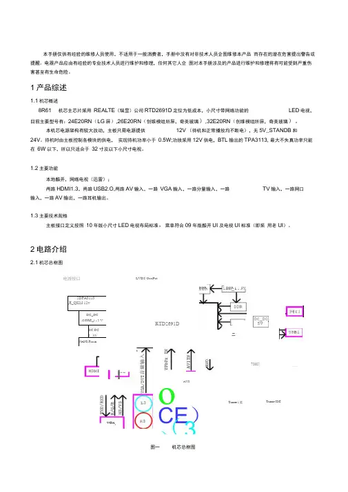
2电路介绍2.1机芯总框图图一机芯总框图LVDS OuuPut5DPA3113(E_QKM 12vDC_DC i2ORE_l a 3 VDC DC 3 . SVNANI FlashRTD2691DoCE )(3)AVI7805|Tuner l 盘——Tuner I2C电游按口I lVGADDR 1 ・ SVDDR二2.2机芯新电路(本机芯特有)1,待机12V 关断电路:图二 待机12V 电源关断电路如图二 所示,C0N12V^ POWER_ElN 号控制。
当正常工作时, POWER_EN 高,Q21导通,Q20的GS 电压在-10V 左右,Q20导通,C0N_12\有电压输出,反之,待机时POWER_EN 低,C0N_12\关断。
电视维修手册第一章:电视故障诊断与维修方法一、电视无法开机当电视无法开机时,首先需要检查以下几个方面:1. 电源插头是否插紧:请确保电源插头已经完全插入电视的电源插座,并且插紧。
2. 电源线是否损坏:检查电源线是否有明显的破损或者断裂情况,如有需要更换新的电源线。
3. 电源开关是否打开:确保电源开关已经打开,有些电视可能有独立的电源开关。
如果以上检查都没有问题,但电视仍然无法开机,可能是以下原因之一:1. 电视主板故障:电视主板是电视的核心部件,如果主板损坏,可能导致电视无法正常开机。
此时建议联系专业维修人员进行维修或更换主板。
2. 电源供应故障:电视的电源供应部分可能出现故障,导致电视无法正常供电。
此时建议联系专业维修人员进行维修或更换电源供应部件。
二、电视无法接收信号或画面不清晰当电视无法接收信号或者画面不清晰时,可以按照以下步骤进行故障排除:1. 检查天线连接:确保电视天线线缆连接牢固,没有松动或者断裂。
如果有需要,可以重新连接天线线缆并确保信号良好。
2. 调整天线方向:有时候电视信号不好是由于天线方向不正确导致的。
可以尝试调整天线的方向,找到最佳的信号接收位置。
3. 检查信号源设备:如果电视无法接收到信号,可能是信号源设备的问题。
可以检查信号源设备(如有线电视盒、DVD播放器等)是否正常工作,以及连接线是否完好。
如果以上步骤都没有解决问题,可能是以下原因之一:1. 电视调谐器故障:电视调谐器是接收信号的重要部件,如果调谐器出现故障,可能导致无法接收信号或者画面不清晰。
此时建议联系专业维修人员进行维修或更换调谐器。
2. 信号源设备故障:如果信号源设备本身出现故障,可能导致电视无法正常接收信号。
此时建议检查信号源设备的工作状态,或者联系专业维修人员进行维修。
第二章:常见电视故障及解决方法一、电视画面出现噪点当电视画面出现噪点时,可以尝试以下方法进行故障排除:1. 调整信号源设备:有时候噪点是由于信号源设备输出信号不稳定导致的。
创维集团有限公司研究院产品机芯维修手册机芯名称:8R19 /8R20/8R21文档名称:8R19 /8R20/8R21调试维修手册当前版本:V00.00正文页数:27拟制:审核:批准:发布日期:2011 年7 月 1 日一、机芯功能简介8R19/8R20/8R21机芯采用Realtek公司RTD2674S为主芯片,外挂一个32Mbit的FLASH和256M的DDR,主芯片采用216脚LQFP封装,内部已集成CPU、中放、图像处理、伴音处理,所以机芯主要特点是集成度高。
本机芯可支持双路8Bit/10Bit LVDS信号,支持HD/FHD屏。
VGA可支持到UXGA(1600X1200)(所有VGA模式只做60hz)。
YPBPR可支持到1920X1080P。
8R19机芯输入/输出接口定义:输入/输出接口规格A V IN 2路(一路侧A V)USB 1路VGA IN 1路YPBPR IN 1路HDMI IN 2路(1.3)VIDEO OUT 1路8R20机芯输入/输出接口定义:输入/输出接口规格A V IN 3路(一路侧A V)Y/C IN 1路VGA IN 1路YPBPR IN 2路HDMI IN 2路(1.3)VIDEO OUT 1路USB 1路8R21机芯输入/输出接口定义:输入/输出接口规格A V IN 2路(一路侧A V)VGA IN 1路YPBPR IN 1路HDMI IN 1路(1.3)VIDEO OUT 1路USB 1路二、系统框图如下,图一、图二,图三分别为8R20、8R19和8R21机芯的系统框图。
图一、8R20的系统框图图二、8R19的系统框图PANEL电源主板LVDS背光连接背光连接CN1 & CN7LVDSBLK_ON BLK_ADJ Power_ON5V_STB GND 12V GND 24VSWD1_2V12VU9:3.3VL35PWR_12VU14:7805TUNER_5VU11:MP1484USB_5VPWR_5VU13:1117-ADJDDR2_5V2674_2V55V_STBU9:8082_DC/DCD3_3A3_3U10:1117-ADJ U12:1084-ADJL36D1_2VTMDS3_3VU3:EEP防串货座子U9:8082U4:DDRU 1:功放U13:LDOU15:主IC 2674SU10:LDOU12:1084U 11:D C _D CHDMIVGAR_outL_outV G A 音频U14:1117副板接口Y12VD2224VD21AMP_VDDU1:功放PWR_5VL28PWR_12VL29PANEL_VCCPb PrAV1AL1AR1AVOUT ALOUT CN2:屏供电AROUTAV2TUNERRF 接口AL2AR2U16USB 接口图三、8R21的系统框图三. 电源网络:如下,图四为主板电源网络分配图耳机图四、电源网络分配图5VSTB 通过SY8082FAC 转化为3.3V ,提供给RTD2674 CPU 供电,此3.3V 又通过U10 AP1117转化为1.26V ,给RTD2674提供内核电压.,见图五。

TCL王牌彩电维修技巧手册1. TCL王牌彩电CPU各脚功能与电压2. TCL210/AS字符无图像无声音测高频头各脚电压,只有AGC电压为0.4V不正常(政常时有信号为5.1V,无信号为6.2V)。
经检查R294(100KΩ)电阻开路。
3. TCL-1419彩电频道低端无台频道低端搜不着台,测高频头VT电压,开始搜索时为0V,当搜索至VL 或VH频道高端时,电压突然由0V增至20V,后慢慢增加且有台出现。
根据现象判断故障在30V调谐电压回路中。
查此回路发现R004(15kΩ)变为无穷大,更换后故障排除。
4. TCL-2101AS彩电不开机接通电源后,待机指示灯亮,按遥控待机开关后,待机指示灯熄灭,屏幕为蓝屏,但几秒钟后,又自动转入待机状态。
待机状态可转换,说明电源及遥控功能正常。
经查是节目存储器ST24C04损坏。
因ST24C04损坏,调谐数据送不到CPU,所以此时是蓝屏。
需要注意的是,2101AS彩电使用的ST24C04E2PROM电擦写只读存储器已由厂家写入初始化数据,而从市面上购买的ST24C04是没有有效数据的芯片,需初始化后才能使用。
5. TCL-2101AS彩电场不同步图象正常,但场不同步。
该机的场同步信号分离及场分频控制电路均在TB1231N 集成块内完成,试更换TB1231N后故障排除。
6. TCL-2111D彩电无光栅该机此类故障通常是末级视放板或显像管有故障造成。
分析发现,如果RGB信号不能送到视放板,会引起IC201(OM8838)18脚反馈电压不正常,从而引起保护电路动作,就会造成彩电开机后指示灯闪烁,屏幕无光栅。
重点检查IC201的确良19、20、21脚的电压,发现C217电容漏电,更换后故障排除。
7. TCL-2111D彩电三无接通电源时待机指示灯闪亮,二次开机后指示灯停闪,说明电源能起振,遥控功能正常。
因为是“三无”故障,怀疑IC201(OM8838)工作不正常。

L42E75 中文维修手册仅用于维修参考目录1 安全与注意事项--------------------------------------------------------------------------21.1 安装注意点------------------------------------------------------------------------21.2 操作使用注意点--------------------------------------------------------------------21.3 存储注意事项----------------------------------------------------------------------21.4 高压警告--------------------------------------------------------------------------22 液晶电视规格----------------------------------------------------------------------------32.1 基本规格--------------------------------------------------------------------------32.2 LCD TV 描述-----------------------------------------------------------------------42.3 电源连接--------------------------------------------------------------------------43 操作说明及调整--------------------------------------------------------------------------53.1 遥控器说明------------------------------------------------------------------------53.2 控制面板--------------------------------------------------------------------------63.3 菜单功能--------------------------------------------------------------------------64 连接介绍-------------------------------------------------------------------------------124.1 背板下方信源接口-----------------------------------------------------------------124.2背板下方信源接口------------------------------------------------------------------144.3 侧面信源接口---------------------------------------------------------------------145 故障处理流程---------------------------------------------------------------------------155.1 主板故障处理---------------------------------------------------------------------155.2 按键板故障处理-------------------------------------------------------------------206 拆卸流程图-----------------------------------------------------------------------------217 PCB LAYOUT-----------------------------------------------------------------------------269.1 主板-----------------------------------------------------------------------------269.2 电源板---------------------------------------------------------------------------289.3 IR 板----------------------------------------------------------------------------309.4 SIDE板---------------------------------------------------------------------------319.5 按键板---------------------------------------------------------------------------31 8 电路图---------------------------------------------------------------------------------3210.1 主板----------------------------------------------------------------------------3210.2 电源板--------------------------------------------------------------------------4410.3 IR板----------------------------------------------------------------------------4510.4 SIDE 板-------------------------------------------------------------------------4610.5 按键板--------------------------------------------------------------------------479 TV电气方框图--------------------------------------------------------------------------4810 TV爆炸图-----------------------------------------------------------------------------4911 白平衡调整----------------------------------------------------------------------------5012 BOM-----------------------------------------------------------------------------------521. 安全与注意事项1.1 安装注意点(1) 请不要用力压或擦、刮液晶表面,不要随意用手触摸显示器的表面。
目录前言⋯⋯⋯⋯⋯⋯⋯⋯⋯⋯⋯⋯⋯⋯⋯⋯⋯⋯⋯⋯⋯⋯⋯⋯⋯⋯⋯⋯⋯⋯⋯⋯⋯⋯⋯⋯⋯⋯⋯2一.R T D 2 6 6 2方案 2 4 " T V电路原理介绍⋯⋯⋯⋯⋯⋯⋯⋯⋯⋯⋯⋯⋯⋯⋯⋯⋯⋯⋯⋯⋯⋯31 . 1R T D2 6 6 2方案 2 4 " T V工作原理方框⋯⋯⋯⋯⋯⋯⋯⋯⋯⋯⋯⋯⋯⋯⋯⋯⋯⋯⋯⋯⋯⋯⋯31 . 2R T D2 6 6 2方案 2 4 " T V主板供路⋯⋯⋯⋯⋯⋯⋯⋯⋯⋯⋯⋯⋯⋯⋯⋯⋯⋯⋯⋯⋯⋯⋯⋯⋯31.3音部分路及工作原理⋯⋯⋯⋯⋯⋯⋯⋯⋯⋯⋯⋯⋯⋯⋯⋯⋯⋯⋯⋯⋯⋯⋯⋯⋯⋯⋯⋯41.3.15532音路及工作原理⋯⋯⋯⋯⋯⋯⋯⋯⋯⋯⋯⋯⋯⋯⋯⋯⋯⋯⋯⋯⋯⋯⋯⋯⋯⋯41. 3 . 2T D A 1 5 1 7音功放路及工作原理⋯⋯⋯⋯⋯⋯⋯⋯⋯⋯⋯⋯⋯⋯⋯⋯⋯⋯⋯⋯⋯⋯⋯51 . 3. 3音多路控制器U501. U502路及工作原理⋯⋯⋯⋯⋯⋯⋯⋯⋯⋯⋯⋯⋯⋯⋯⋯⋯⋯⋯5 1.4 高路及工作原理⋯⋯⋯⋯⋯⋯⋯⋯⋯⋯⋯⋯⋯⋯⋯⋯⋯⋯⋯⋯⋯⋯⋯⋯⋯⋯⋯⋯⋯⋯61.5 出及路工作原理⋯⋯⋯⋯⋯⋯⋯⋯⋯⋯⋯⋯⋯⋯⋯⋯⋯⋯⋯⋯⋯⋯⋯⋯⋯⋯⋯61.6屏供控制路及工作原理⋯⋯⋯⋯⋯⋯⋯⋯⋯⋯⋯⋯⋯⋯⋯⋯⋯⋯⋯⋯⋯⋯7 1.7FLASH路工作原理⋯⋯⋯⋯⋯⋯⋯⋯⋯⋯⋯⋯⋯⋯⋯⋯⋯⋯⋯⋯⋯⋯⋯⋯⋯⋯⋯⋯⋯⋯⋯7二.常见故障的判断及简修⋯⋯⋯⋯⋯⋯⋯⋯⋯⋯⋯⋯⋯⋯⋯⋯⋯⋯⋯⋯⋯⋯⋯⋯⋯⋯⋯⋯72.1无⋯⋯⋯⋯⋯⋯⋯⋯⋯⋯⋯⋯⋯⋯⋯⋯⋯⋯⋯⋯⋯⋯⋯⋯⋯⋯⋯⋯⋯⋯⋯⋯⋯⋯⋯⋯⋯⋯7 2.2无光⋯⋯⋯⋯⋯⋯⋯⋯⋯⋯⋯⋯⋯⋯⋯⋯⋯⋯⋯⋯⋯⋯⋯⋯⋯⋯⋯⋯⋯⋯⋯⋯⋯⋯⋯⋯8 2.3保、无光⋯⋯⋯⋯⋯⋯⋯⋯⋯⋯⋯⋯⋯⋯⋯⋯⋯⋯⋯⋯⋯⋯⋯⋯⋯⋯⋯⋯⋯⋯⋯⋯8 2.4白屏⋯⋯⋯⋯⋯⋯⋯⋯⋯⋯⋯⋯⋯⋯⋯⋯⋯⋯⋯⋯⋯⋯⋯⋯⋯⋯⋯⋯⋯⋯⋯⋯⋯⋯⋯⋯8 2.5关机白屏⋯⋯⋯⋯⋯⋯⋯⋯⋯⋯⋯⋯⋯⋯⋯⋯⋯⋯⋯⋯⋯⋯⋯⋯⋯⋯⋯⋯⋯⋯⋯⋯⋯⋯⋯9 2.6 TV()无台或偏色⋯⋯⋯⋯⋯⋯⋯⋯⋯⋯⋯⋯⋯⋯⋯⋯⋯⋯⋯⋯⋯⋯⋯⋯⋯⋯⋯⋯9 2.7声音不良⋯⋯⋯⋯⋯⋯⋯⋯⋯⋯⋯⋯⋯⋯⋯⋯⋯⋯⋯⋯⋯⋯⋯⋯⋯⋯⋯⋯⋯⋯⋯⋯⋯⋯⋯9 2.8V G A入无信号⋯⋯⋯⋯⋯⋯⋯⋯⋯⋯⋯⋯⋯⋯⋯⋯⋯⋯⋯⋯⋯⋯⋯⋯⋯⋯⋯⋯⋯⋯⋯⋯⋯102.9L C D示屏常故障⋯⋯⋯⋯⋯⋯⋯⋯⋯⋯⋯⋯⋯⋯⋯⋯⋯⋯⋯⋯⋯⋯⋯⋯⋯⋯⋯⋯⋯⋯⋯102.10T V内置源不良⋯⋯⋯⋯⋯⋯⋯⋯⋯⋯⋯⋯⋯⋯⋯⋯⋯⋯⋯⋯⋯⋯⋯⋯⋯⋯⋯⋯⋯⋯⋯⋯10三、软件烧录及工厂复位⋯⋯⋯⋯⋯⋯⋯⋯⋯⋯⋯⋯⋯⋯⋯⋯⋯⋯⋯⋯⋯⋯⋯⋯⋯⋯⋯⋯⋯113.1 RTD2662 方案通USB 接口接⋯⋯⋯⋯⋯⋯⋯⋯⋯⋯⋯⋯⋯⋯⋯⋯⋯⋯⋯⋯⋯⋯⋯113. 2 通主机及用板板 FLASH 行⋯⋯⋯⋯⋯⋯⋯⋯⋯⋯⋯⋯⋯⋯⋯⋯⋯113.3E D I D⋯⋯⋯⋯⋯⋯⋯⋯⋯⋯⋯⋯⋯⋯⋯⋯⋯⋯⋯⋯⋯⋯⋯⋯⋯⋯⋯⋯⋯⋯⋯⋯⋯⋯⋯14 3.4入工厂模式及工厂复位方法⋯⋯⋯⋯⋯⋯⋯⋯⋯⋯⋯⋯⋯⋯⋯⋯⋯⋯⋯⋯⋯⋯⋯⋯⋯⋯163.4.1入工厂模式⋯⋯⋯⋯⋯⋯⋯⋯⋯⋯⋯⋯⋯⋯⋯⋯⋯⋯⋯⋯⋯⋯⋯⋯⋯⋯⋯⋯⋯⋯⋯163.4.2工厂复位⋯⋯⋯⋯⋯⋯⋯⋯⋯⋯⋯⋯⋯⋯⋯⋯⋯⋯⋯⋯⋯⋯⋯⋯⋯⋯⋯⋯⋯⋯⋯⋯⋯⋯16四.维修中注意事项⋯⋯⋯⋯⋯⋯⋯⋯⋯⋯⋯⋯⋯⋯⋯⋯⋯⋯⋯⋯⋯⋯⋯⋯⋯⋯⋯⋯⋯⋯⋯16前言全国各授权维修中心:随着我公司 KTC液晶自有品牌市占有率不断提高,在目前液晶于同化的市争境下,售后服的重要性尤突出,修服量和及性更重要。
FOR SERVICE TECHNICIAN’S USE ONL YFOR SERVICE TECHNICIAN’S USE ONL YFOR SERVICE TECHNICIAN’S USE ONL Y324FOR SERVICE TECHNICIAN’S USE ONL YT ech SheetDo not discardFOR SERVICE TECHNICIAN’S USE ONLYPRECAUTIONS TO BE OBSERVED BEFORE AND DURING SERVICING TO AVOID POSSIBLE EXPOSURE TO EXCESSIVE MICROWAVE ENERGYa. Do not operate or allow the oven to be operated with the dooropen.b. Make the following safety checks on all ovens to be servicedbefore activating the magnetron or other microwave source, and make repairs as necessary:1. Interlock Operation 2. Proper Door Closing3. Seal and Sealing Surfaces (Arcing, Wear and Other Damage)4. Damage to or Loosening of Hinges and Latches5. Evidence of Dropping or Abusec. Before turning on microwave power for any service test orinspection within the microwave generating compartments, check the magnetron, wave guide or transmission line, and cavity for proper alignment, integrity and connections.d. Any defective or misadjusted components in the interlock,monitor, door seal, and microwave generation and transmission systems shall be repaired, replaced, or adjusted by procedures described in this manual before the oven is released to the owner.e. A microwave leakage check to verify compliance with the FederalPerformance Standard should be performed on each oven prior to release to the owner.f. Do not attempt to operate the oven if the door glass is broken.FAILURE CODE INDICATIONSNOTE: Many of the problems listed in the chart below may be solved by power cycling: Unplug microwave oven or disconnect power. After 1 minute, plug in microwave oven or reconnect power.Display Likely Failure Condition Recommended Repair Procedure“Enter clock”Power failureAfter a power failure, “Enter clock” will be flashing. Press CANCEL to end this indication. The colon (:) will appear when in Standby mode.F1E4Microwave ACU failure 1. Unplug microwave oven or disconnect power.2. Replace ACU.3. Replace all parts and panels before operating.4. Plug in microwave oven or reconnect power.F2E1Stuck key failure1. Unplug microwave oven or disconnect power.2. Replace touch panel.3. Replace all parts and panels before operating.4. Plug in microwave oven or reconnect power.F4E4Humidity sensor error 1. Enter the Diagnostics mode (press CANCEL - CANCEL- START), and then press COOK TIME to display the humidity sensor reading. If display does not show “3789,” continue to Step 2. Press COOK POWER to display the RH sensor NTC reading. If display does not show “026,” continue to Step 2.2. Unplug microwave oven or disconnect power.3. Connect a new humidity sensor ACU to cable.4. Replace all parts and panels before operating.5. Plug in microwave oven or reconnect power.6. Enter the Diagnostics mode (press CANCEL - CANCEL - START), then press COOKTIME, and then press COOK POWER to see if failure code reappears.NOTE: There may be a delay (approximately 1 minute, 20 seconds) before the F4E4 failure code is displayed.7. If the F4E4 failure code reappears, unplug microwaveoven or disconnect power.8. Replace ACU.9. Replace all parts and panels before operating.10. Plug in microwave oven or reconnect power.F8E5Exhaust air templatedetection failure1. Enter the Diagnostics mode (pressCANCEL - CANCEL - START), and then press OPTIONS/CLOCK to display the exhaust air temperature sensor reading. Verify the sensor temperature reading is at room temperature (typically 50ºF to 90ºF [10ºC to 32ºC]) and verify failure code. If failure code matches complaint, continue to Step 2.2. Unplug microwave oven or disconnect power.3. Disconnect sensor from ACU.4. Measure sensor resistance between connector pinsand confirm reading is between 9.5 kΩ and 10.5 kΩ at room temperature. If measurement is not correct, or if a short or open circuit is found, replace sensor.5. Replace all parts and panels before operating.6. Plug in microwave oven or reconnect power.7. Enter the Diagnostics mode (pressCANCEL - CANCEL - START), and then pressOPTIONS/CLOCK to display the cavity temperature sensor reading. Verify the sensor temperature reading. If it is still not correct, replace ACU.8. If failure does not reappear, stop.PRIMARY , MONITOR, SECONDARY , AND DOOR INTERLOCK SWITCH CHECKOUT PROCEDURESIMPORTANT: Before checking the interlock switches, unplug microwave oven or disconnect power. Be sure to disconnect all of the wires at the switch being tested before making any continuity readings.NOTE: The Primary Interlock switch, Monitor Interlock switch, Secondary Interlock Switch, and Door Interlock Switch are mounted in the door lockswitch cradle. All the Interlock Switches can be identified by the wire colors that are connected to the terminals of the switches. See the chart below for wire color designation.SwitchCheck ByDoor OpenDoor ClosedPrimary Interlock1. Unplug microwave oven or disconnect power.2. Disconnect the wires at the Primary Interlock Switch.3. Check from the common terminal (black/brown wires) to the normally open terminal(black/white wires).4. Reconnect wires to switch.-+Monitor Interlock 1. Unplug microwave oven or disconnect power.2. Disconnect the wires at the Monitor Interlock Switch.3. Check from the common terminal (white wire) to the normally closed terminal(blue/white wires).4. Reconnect wires to switch.+-Secondary Interlock 1. Unplug microwave oven or disconnect power.2. Disconnect the wires at the Secondary Interlock Switch.3. Check from the common terminal (white/blue wires) to the normally open terminal(blue/blue wires).4. Reconnect wires to switch-+Door Interlock 1. Unplug microwave oven or disconnect power.2. Disconnect the wires at the Door Interlock Switch.3. Check from the common terminal (blue wire) to the normally closed terminal(orange wire).4. Reconnect wires to switch.+-(+) Continuity (-) No ContinuityM W O v e n R u n n i n g —A C V R e a d i n g sP i n N a m eW i r e C o l o rP o w e r O n , D o o rC l o s e dP o w e r O n , D o o r O p e nH o o d F a n M o t o r —H i g hH o o d F a n M o t o r —H i g h , D o o r O p e nH o o d F a n M o t o r —M e d -H i g hH o o d F a n M o t o r —M e d -H i g h , D o o r O p e nH o o d F a n M o t o r —M e d i u mH o o d F a n M o t o r —M e d i u m , D o o r O p e nH o o d F a nM o t o r —L o wH o o d F a n M o t o r —L o w , D o o r O p e nH o o d L i g h t —H ig hH o od L i g h t —H i g h , D o o r O pe nH o o d L i g h t —L o wH o o d L i g h t —L o w , D o o r O p e nM W O v e n S t a r t P1-1 (L)Brown 120120120120120120120120120120120120120120120P1-3 (N)White 00 0000000000000P2-3 (NFS)White 0120012001200120012001200120 3.6P2-2 (Door)Orange 012001200120012001200120012049P2-1 (N)Green 000000000000000P4-4 (HF)White 01200120012001200120012000120P4-5 (TTM)Red 0120012001200120012001200120120P4-1 (HL)Yellow 00000000001201206767 2.4P4-2 (HF-R)Gray 00120120120120585877770000 3.6P4-3 (HF-Hi)Black001201206868585839390000 3.7P4-6 (CL)Green151151120120555577773.7CONNECTORS ON ACUTOUCH P ANELT ouch Panel and ACU T estThe microwave hood combination is provided with a self-diagnostic routine that can be accessed through the touch keypad.T o initiate this routine:1. Plug in microwave oven or reconnect power, and press CANCEL tostandby (“:”).2. Close door, then press CANCEL - CANCEL - START within3 seconds.3. All display segments will be lit to indicate the Test mode has beenentered.NOTE: If CANCEL is pressed during this diagnostic routine, you will exit the Test mode.ACU21P41 2 3 4 5 6Relay 4903P11 3L N.P91 2P111 2 3 4P6 3 2 1P21 2 3P3 14 13 12 11 10 9 8 7 6 5 4 3 2 1P71234567891011Relay 490321NOTE: There are purposely emptyterminals between each of the numbered terminals on P1 connector.W11268419ANOTE: These diagrams are not intended to show a complete circuit; they represent the position of switches during “DOOR OPEN” or “DOOR CLOSED” (continuity checks only).NOTE: Interlock, Monitor switches and Door interlock switch cannot be adjusted and all these switches should be replaced if any one of them is found to be defective. After replacing interlock/monitor switches, reconnect wires to switch and check for continuity. Safety interlocks and monitor switches will actuate within 2 mm.Door ClosedDoor OpenNOT HEATING TROUBLESHOOTING INSTRUCTIONIMPORTANT: High-voltage is present at the magnetron and high-voltage capacitor terminals. Avoid direct contact when power is connected to these components to avoid serious injury or possible death. Always be sure that the high-voltage capacitor is discharged before accessing any of these components.For a no-heat condition, refer to the following step-by-step instructions:1. Unplug microwave oven or disconnect power.2. Discharge the high-voltage capacitor.3. Disconnect the high-voltage transformer primary windings.4. Attach the voltmeter leads to the high-voltage transformer primaryinput wires.5. Plug in microwave oven or reconnect power.6. Close door and program the microwave oven to operate for30 seconds.7. Press START.8. Check the input voltage at the high-voltage transformer primary inputwires. If the voltage is not close to the rating voltage 120 +/-15 VAC, unplug microwave oven or disconnect power. Check the circuitry as follows:■Measure resistance of the fuse, microswitches and thermostats. Replace any failed components. (Refer to the wiring diagram.)■Check for loose terminals. (Refer to the wiring diagram.) Check all of the terminals on the main route from the power supply to the high-voltage transformer.■Check for loose or failed connectors on the ACU (P1, P2, P4). Ifthese check out OK, plug in microwave oven or reconnect power. ■Check for ACU failure. Refer to the “ACU Pin Voltage Matrix” section.9. If the input voltage at the high-voltage transformer primary inputwires is close to the rating voltage 120 +/-15 VAC, unplug microwave oven or disconnect power.10. Check the power supply components. Refer to the “ComponentTests” section.■High-voltage transformer ■High-voltage capacitor■High-voltage diode11. If the power supply components check out OK, check the connectionbetween the magnetron and the high-voltage transformer.12. If all of the components check out OK, replace the magnetron.13. Reconnect the high-voltage transformer primary windings.ACU PIN VOLTAGE MATRIXCheck for proper voltage by completing the following steps:1. Unplug microwave oven or disconnect power.2. Connect voltage measurement equipment to the terminals listedbelow. (P1-3 and P2-3 are neutral.) 3. Plug in microwave oven or reconnect power, and confirm voltagereading.4. Unplug microwave oven or disconnect power.NOTE: For 50 V and over, the tolerance is +/-15 V . For 0 V , the tolerance is +/-3 V .AbbreviationsHL – Hood LightN – NeutralCL – Cavity LightHF – Hood FanL – Line VoltageTT – Turntable MotorNFS – Neutral for SwitchNOTE: When checking voltage readings on ACU, connect the grounding test lead of voltmeter to P1-3, P2-1. Use the positive test lead to probe connectors designated below.Door Interlock SwitchSecondary Interlock Switch(NO)Interlock SwitchDoor Interlock SwitchMW Oven Plugged In—Sitting Idle—ACV ReadingsFOR SERVICE TECHNICIAN’S USE ONL Y FOR SERVICE TECHNICIAN’S USE ONL YFOR SERVICE TECHNICIAN’S USE ONL Y FOR SERVICE TECHNICIAN’S USE ONL Y 57608/18FOR SERVICE TECHNICIAN’S USE ONLYW11268419A©2018 All rights reserved.Components Test/ResultsH.V. Transformer 1. Unplug microwave oven or disconnect power.2. Remove wire leads.3. Measure resistance:■Primary winding: Less than 0.5 ohm (approximate)■Secondary winding: 120 ohms (approximate)■Filament winding: 0 ohms■Primary winding to grounding: Normal: Infinite■Filament winding to grounding: Normal: InfiniteMagnetron 1. Unplug microwave oven or disconnect power.2. Remove wire leads.3. Measure resistance:■Filament terminal: Normal: Less than 1 ohm■Filament to chassis: Normal: InfiniteH.V. Capacitor 1. Unplug microwave oven or disconnect power.2. Remove wire leads.3. Measure resistance:■Terminal to terminal: Normal: Momentarily indicates several ohms and then gradually returns toinfinite.■Terminal to case: Normal: InfiniteH.V. Diode NOTE: Some inexpensive meters may indicate infinite resistance in both directions.1. Unplug microwave oven or disconnect power.2. Measure resistance:■Forward: Normal: Continuity■Reverse: Normal: InfiniteTurntable Motor 1. Unplug microwave oven or disconnect power.2. Remove wire leads.3. Measure resistance:■Normal: 2.4k to 3.2k ohms (approximate)Motor Capacitor 1. Unplug microwave oven or disconnect power.2. Remove wire leads.3. Measure motor capacitor:■Normal: Momentarily 0 ohms, then goes to infinite1. Unplug microwave oven or disconnect power.2. Remove the 4-pin connector from the cable.3. Measure resistance across pins 1 and 2.■Normal: 10k ohms +/-5% at 77°F (25°C)4. Measure capacity value across pins 3 and 4.■Normal: 180pF +/-5% at 55% RHHood Exhaust Fan Motor 1. Unplug microwave oven or disconnect power.2. Remove wire leads.3. Measure resistance:■High Speed—Normal: Red (RD) and Blue (BU) wires: 70 to 100 ohms (approximate); Blue (BU) andBlack (BK) wires: 30 to 60 ohms (approximate)■Low Speed—Normal: Red (RD) and Blue (BU) wires: 70 to 100 ohms (approximate); Blue (BU) andWhite (WH) wires: 50 to 80 ohms (approximate)HF NTC Thermistor 1. If “NTC SHORT, CALL FOR SERVICE” or “NTC OPEN, CALL FOR SERVICE” scrolls on display, unplugmicrowave oven or disconnect power.2. Measure resistance:■Normal: 10k ohms +/-5% at 77ºF (25ºC)Power Resistor 1. Unplug microwave oven or disconnect power.2. Remove wire leads.3. Measure resistance:■Normal: 65 ohms/65 WPrimaryFilament(orange/red wires)Secondary (whitewire - ground totransformer case)23Components Test/ResultsCooling Fan Motor 1. Unplug microwave oven or disconnect power.2. Remove wire leads.3. Measure resistance:■Normal: 40 to 60 ohms (approximate)AC Line Filter Board 1. Unplug microwave oven or disconnect power.2. Remove wire leads.3. Measure resistance:■Normal: L-IN to L-OUT (coil): Less than 1 ohm; N-IN to N-OUT (coil): Less than 1 ohmThermostats NOTE: Refer to “Parts Layout” for opening and closing temperatures.1. Unplug microwave oven or disconnect power.2. Remove wire leads.3. Measure continuity:■Normal: ContinuitySCHEMATIC DIAGRAMCavity ThermostatMagnetron ThermostatCavityzH6V521/V21CAKey T ables for T est ModeKey Name Function Display BuzzerPopcorn-key 30 1 beepPotato orBaked Potato-key 31 1 beepVegetable-key 2E 1 beepFrozen Entrée-key 33 1 beepSteam Simmeror Steam Cook-key 2D 1 beepWarm Hold-key 06 1 beepReheat-key 24 1 beepDefrost-key 25 1 beepSoften/Melt-key 29 1 beepCook Time Humidity sensorcheckValue between2000 and 60001 beepCook Power RH NTC sensorcheckValue between10 and 401 beepCook key 07 1 beepTimer Set/Off-key 05 1 beepOptions/Clock HF NTC Thermistor XXX 1 beepStart or Software/Geeversion check*xx.xx.xx 1 beepAdd 30 Sec or +30Sec key 20 1 beepDinner Plate-key 32 1 beepBeverage-key 34 1 beepPizza-key 35 1 beep* Continuously pressing START or will respectively display SW Versionand Gee Version for each press.Key Name Function Display Buzzer1Cavity Light andCooling Fan OnCL 1 beep2Cavity Light, CoolingFan and Turntable OnCL TT 1 beep3-key 36 1 beep4-key 14 1 beep5-key 15 1 beep6Hood (Cooktop) LightOn (High)HL HIGH 1 beep7Hood (Cooktop) LightOn (Low)HL LOW 1 beep8Vent Fan On (HighSpeed)HF HIGH 1 beep9Vent Fan On (LowSpeed)HF LOW 1 beep0Microwave Oven(1000 W), CL, TT andCF On for 10 SecondsMW 1 beepLight or -key 03 1 beepTurntable -key 09 1 beepPOWER OUTPUT MEASUREMENTThe power output of the magnetron can be measured using the following“Voltage Measurement” and “Output Test” sections. Before you performthe test:■Make sure that the oven cavity is cool and clean.■Check the line voltage at the wall outlet while microwave oven isoperating. See the “Voltage Measurement at Power Source” section.T ools Needed■2-cup measuring cup■Thermometer■Voltmeter/ohmmeterVoltage Measurement at Power Source1. Fill the measuring cup with 2 cups (500 mL) of tap water.2. Place in the center of the microwave oven cavity.3. Operate the microwave oven on High speed for 1 minute.4. While the microwave oven is operating, measure the line voltage atthe power source. See “Measure Voltage” illustration.5. Verify the voltage is constant during microwave oven operation. Ifvoltage drops below 108V, contact a qualified electrician to checkyour electrical supply.6. Make note of the voltage while the microwave oven is running andproceed to the output test.Measure VoltageOutput T est1. Fill the measuring cup with 2 cups (500 mL) of 70ºF (21ºC) tap water.2. Stir the water with the thermometer to ensure uniform temperature.Add warm or cool water to bring the water to the correct temperature.3. Place the measuring cup in the center of the microwave oven cavity.4. Operate the microwave oven on High speed for 1 minute.5. Remove the measuring cup and stir the water with the thermometerfor about 20 seconds.6. Record the temperature of the water.7. Refer to the model serial tag on the microwave oven to acquirewattage output rating of the microwave oven.8. Using the following chart, determine if the output of the microwaveoven is within the range listed based on the line voltage and wattagerating of the microwave oven.Water Temperature for Line Voltage and Wattage RatingVoltage700 W1000 W1200 W120 V96ºF to 102ºF(36ºC to 39ºC)110ºF to 116ºF(43ºC to 47ºC)124ºF to 130ºF(51ºC to 54ºC)108 V91ºF to 97ºF(33ºC to 36ºC)101ºF to 107ºF(38ºC to 42ºC)111ºF to 117ºF(44ºC to 47ºC)COMPONENT TESTSAA. House power supply wall outletB. Voltmeter/Ohmmeter test leadsC. Microwave oven plugP ARTS LA YOUT (NOT TO SCALE)A. Line fuse (20 amp)B. AC line filter boardC. Hood fan motor assemblyD. Cavity lightE. Cavity light holderF. MagnetronG. Magnetron thermostat—opens at 257ºF (125ºC), closesat 185ºF (85ºC)H. Power resistorI. H.V. capacitorJ. H.V. diodeK. H.V. transformerL. Motor capacitorM. Cooling fan motorN. HF NTC thermistorO. ACUP. Touch panelQ. Secondary interlock switchR. Door interlock switchS. Monitor interlock switchT. Primary interlock switchU. Turntable motorV. Hood (cooktop) lightW. Hood (cooktop) light holderX. Cavity thermostat—opens at 257°F (125°C), non-resettableY. Humidity sensor ACUIMPORTANT:■Unplug microwave oven or disconnect power.■Discharge the high-voltage capacitor and remove thelead wires from the primary winding of the high-voltagetransformer before conducting any of the following tests.■Remove the lead wires from the related component beforeconducting any of the following tests.■All operational checks using microwave energy must be donewith the microwave oven loaded with a minimum of 8 oz(250 mL) of water in a microwave-safe container.■Conduct a microwave energy test after performing any testsor repairs to the microwave oven.■Check that all wire leads are in the correct positions beforeoperating the microwave oven.■Grasp wire connectors when removing the wire leads frommicrowave oven parts.■All testing must be done with an ohmmeter having asensitivity of 20,000 ohms per volt DC or greater andpowered by at least a 9 V battery.。
TCL彩电维修资料4机型:LCD27K73 机芯 MS88故障:灯亮不开机检修与分析:5V有电压,没 12V 和 24V输出,测量 PFC有 385伏的电压,说明PFC已经工作,12V和24V 有IC3控制输出的,由11,15脚输出控制信号的,控制QW9,QW10交替导通。
QW9,QW10组成半桥整流电路,测量其供电11脚电压正常,15脚正常,当测量到7脚时发现电压,不正常,发现RW13,一端有电压,一端电压偏低,发现RW13,1M的电阻开路,更换后12V 24V电压正常了。
(郑州分公司周口许富收)机型:LCD27K73故障现象:开机灰屏无图有声分析与检修:根据故障现象,断定故障出在显示屏部分。
背光正常,问题肯定出在中心控制板上。
此机用的是友达的屏(T260XW03—V.2)。
拆下电路板,试着检测其电路是否工作正常。
用电压检查法先测量此板的工作电压,发现板上的U202(L117—1.7V)三端稳压没有输出,而U202的输入端电压(3.3V)正常。
在换掉U202之前用数字表测量其输出脚的对地阻值(黑表笔接地,红表笔测量,放在测量晶体管的档位),没有短路迹象,表头显示500左右。
换新U202,开机测其电压1.7V正常。
装好此板开机,显示回复正常,试机 2小时后断定故障排除。
(西安公司乔立江提供)机型:LCD27K73故障现象:灯亮不开机分析与检修:红灯亮不开机,问题应该出现在数字板上,首先检测 MST718BU的供电、晶振、复位、总线电压都正常,随即更换存储器 24C16开机仍然是灯亮不开机,更换FLISH故障依旧,此时维修没有方向,分析图纸后认为问题还是应该出现在 718BU上应该是它的某个条件不符合,代换晶振、718BU本身都无效果,测量39、42脚电压也为 1.25正常,维修陷入困境,查找 718BU的引脚功能发现 72脚也是复位测量72脚电压为2V多,正常的为0V这说明问题就在这,而 72脚的外围电路就是一只电阻 R193接地,测量 R193两端没有压降,测量电阻阻值正常为1K,测量电阻对地端与地之间的阻值为无穷大这说明对地端开路,连线处理后故障排除。