Volume Ray Casting on CUDA
- 格式:pdf
- 大小:205.97 KB
- 文档页数:18

基于射线管分裂方法的SAR场景快速消隐技术董纯柱;殷红成;王超【摘要】SAR场景模型常采用非均匀三角网格描述,使得传统的基于Z-Buffer技术的消隐算法难以在保持较高的消隐精度的同时兼顾消隐效率。
该文提出了一种基于射线管分裂方法的 SAR 场景快速消隐技术,将复杂 SAR 场景的消隐问题分解为两个简单过程:一是对场景三角网格在发射平面上的投影点云做2维Delaunay 三角网格划分,二是基于射线管分裂方法对新生网格可见性进行判断和拓扑重构。
典型飞机目标和草地上T-72坦克的消隐结果验证了该方法的准确性和高效性。
% Traditional hidden surface removal algorithm based on hardware Z-Buffer technique cannot give attention to precision or efficiency at the same time when dealing with the non-uniform triangulated SAR (Synthetic Aperture Radar) scene model. A novel high-precision hidden surface removal approach using fast ray-tube splitting algorithm is proposed, where the SAR scene hidden surface removal problem is decomposed into two simple procedures, i.e. a Delaunay triangulator is used to generate the initial ray tubes from the projected point clouds of all incident visible vertices, then an adaptive ray-tube splitting method is adopted to carry out the complex scene shading situations and resultant visible model reconstruction. Simulation results of typical aircraft and T-72 tank show that, the new approach is feasible and effective.【期刊名称】《雷达学报》【年(卷),期】2012(000)004【总页数】5页(P436-440)【关键词】消隐算法;射线管分裂方法;Delaunay三角剖分;Z-Buffer算法;SAR场景【作者】董纯柱;殷红成;王超【作者单位】中国传媒大学信息工程学院北京 100024; 电磁散射重点实验室北京100854;中国传媒大学信息工程学院北京 100024; 电磁散射重点实验室北京100854;电磁散射重点实验室北京 100854【正文语种】中文【中图分类】TN957对基于模板匹配的SAR图像解译而言,SAR图像中特有的透视收缩、叠掩和阴影等几何畸变特性是重要且稳定的识别特征[1]。
1. Image Sampler (Antialiasing 图像采样(抗锯齿2. Depth of field/Antialiasing filter 景深/抗锯齿过滤器3. Indirect Illumination (GI / Advaneed irradianee map parameters间接照明(全局照明GI /高级光照贴图参数4. Caustics散焦5. En vir onment 环境6. Motion blur运动模糊7. QMC samplers QMC 采样8. G-buffer G-缓冲9. Camera摄像机10. Syste m 系统1. Image Sampler (Antialiasing 图像采样(抗锯齿VRay采用几种方法来进行图像的采样。
所有图像采样器均支持MAX的标准抗锯齿过滤器,尽管这样会增加渲染的时间。
你可以选择Fixed rate采样器,Simple two-level 采样器和Adaptive subdivision 采样器。
Fixed rate 采样这是最简单的采样方法,它对每个像素采用固定的几个采样。
Subdivs —调节每个像素的采样数。
Rand -当该选项选择后,采样点将在采样像素内随机分布。
这样能够产生较好的视觉效果。
Simple two-level采样一种简单的较高级采样,图像中的像素首先采样较少的采样数目,然后对某些像素进行高级采样以提高图像质量。
Base subdivs-决定每个像素的采样数目。
Fine subdivs -决定用于高级采样的像素的采样数目。
Threshold -所有强度值差异大于该值的相邻的像素将采用高级采样。
较低的值能产生较好的图像质量。
Multipass -当该选项选中后,当VRay对一个像素进行高级采样后,该像素的值将与其临近的未进行高级采样的像素的值进行比较。
当它们的差值大于Threshold值时,这些临近的像素也将被进行高级采样。

VRay 渲染器参数VRay :Authorization(授权)主要是设置填写当前系统计算机的计算机名称或IP 地址以保证VRay 服务器程序文件运行,确认填写正确后就可以重新启动MAX 来使用了About VRay (关于VRay )显示当前版本以及官方连接。
VRay :Frame buffer (帧缓存器)对静帧画面御览和调整。
VRay :Globil switches (全局开关)控制和调整渲染总体环境设定。
VRay :Image sampler(Antialiasing)(图像采样)图像采样参数选项和使用调和阴影来使图象线条的锯齿边平滑的过程选项。
VRay :Indirect illumination(GI)(间接照明)启用(GI )全局光照,计算光子在物体间的反弹。
VRay :Irradiance map (发光贴图)记录和调用GI 计算后的结果数据来渲染图像。
VRay : Quasi-Monte Carlo GI (类蒙特卡洛Gl)—种GI 计算标准。
VRay : Caustics (焦散)计算光反弹/折射后的光汇集状况。
VRay : Environment (环境)启用环境(天光)光源和反射/折射环境源。
VRay : QMC Sampler (类蒙特卡洛采样)类蒙特卡洛计算标准的采样设定。
VRay::Color mapping (色彩贴图)渲染通道和色彩饱和的选项设定。
VRay : Camera (摄像机)对摄像机的控制。
VRay; : Default displacement (默认置换)默认置换认的参数设置。
VRay : System (系统)系统控制参数及打开信息提示。
VRay Frame buffer (帧缓存器)Enable built-in Frame Buffer (使嵌入的帧缓冲器能够使用)选择启用帧缓存。
Get resolution from MAX (从MAX 获取分辨率)使用MAX 设定的图像输出分辨率。
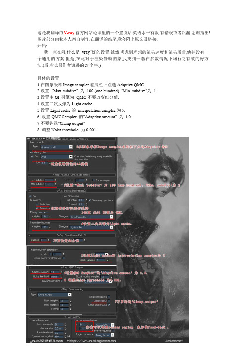
这是我翻译的V-ray官方网站论坛里的一个置顶贴.英语水平有限.有错误或者纰漏,谢谢指出!图片部分由我本人亲自制作.在翻译的结尾,我会附上原文及链接.开始:我一直在问,什么是vray”好的设置.诚然.考虑到理想的渲染速度和渲染质量,他并没有一个通用的方案.但是,在此对于渲染静帧图象,我找到一套在多数情况下均行之有效的好方法.(后,省去原作者谦逊的N个字.)具体的设置1在图象采样Image sampler卷展栏下点选Adaptive QMC2设置"Max. subdivs" 为100 (one hundred). "Min. subdivs"为13设置主GI 引擎为QMC不要改变细分值.4设置二次反弹为Light cache5设置Light cache的interpolation samples为5.6 设置QMC Sampler 的"Adaptive amount" 为1.0.7不要钩选"Clamp output"8 调整Noise threshold 为0.001控制渲染时间与质量:1 调整QMC Noise threshold.值越低噪点越少,但会增加渲染时间2 根据场景大小调整light cache细分值. 一般设置到1000—5000足以应付大多数场景.当然你也可以根据需要调整LC的其他参数.3 依据需要打开或者关掉reflective/refractive GI caustics.4 可以打开Use light cache for glossy rays来加快模糊反射.5 你也可以调整render region 来加快feed-back注意1 保留其他所有细分值为缺省值.2 对于1.49,30以前的版本,请不要使用Linear 以外的的color mapping 否则会出现错误,如果需要可以调整color correction .3 避免使用锐化的AA滤镜优势1 以很少的参数控制渲染质量.2 适应很多场景的渲染.3 可以渲染出高质量的作品.劣势1可能比较慢v-ray 入门(1)——全局光照明v-ray 入门(1)——全局光照明我个人的理解, vray 将渲染计算分为两部分第一部分计算漫反射阶段 ( 打开GI )vray有两种方式可可供选择来计算漫反射1)直接强制计算,计算结果直接与直接光照结果混合计算. 这时屏幕不出现I-map图注意: 一次反射, 二次及二次以上反射的计算方法不同, 对于一次反弹, 加大subdivs 渲染时间爆增, 对于二次及二次以上反弹, 加大subdivs则渲染时间增加的不如一次反弹来得明显2) I-map计算方式, 将计算结果变成一种贴图 I-mapI- map是一种光线贴图,它主要是表现漫反射的光照,与材质(shade)表现,贴图表现光线跟踪材质及贴图并无直接关系,控制这些表现的是vray中的Image sampler (Anti-aliasing)下的参数.也就是说:Image sampler (Anti-aliasing)下的参数不光控制着抗锯齿效果,也控制着材质及贴图的表现在进行I-map的GI计算时第一步vray从光源分别对场景发射向每个pixel发射出出 hsph个光线,每条光线碰到场景中的物体后,根据I-map上的材质特性进行了反弹,一次反弹的mul值实际上是的第一次反弹光线的强度,饱和度,亮度前面的放大系数第二步第二次反弹的sub确定反弹光线的个数,假如 hsph为10, sub 为1, 那么就是说第二次反弹中,10条光线反弹才反弹出一条光线,三次四次反弹与二次反弹的光线相同. 当hsph为10, sub为20, 二次反弹中,10条光线反弹才反弹出20条光线, 三次四次反弹与二次反弹的光线相同注意:二次三次反弹的计算方法与一次反弹的计算方法不同,增加sub值,渲染时间增加不多,建议hsph=sub反弹几次由参数depth确定,二次三次反弹前也有放大系数mul第三步: vray在每个pixel上取insterp个采样点,将光照信息存入 I-map,在render 时,在这interp个采样点上,以贴图的方式插入渲染结果注意:I-map与相机视图相关,移动相机,I-map必须重新计算,在动画中,vray一般每10帧算一幅 I-mapvray中参数对渲染时间的敏感程度有大到小为:max > min > hsph > Clr thershold 和Normr thershold > depth > sub > interp你可将400x320图幅的I-map用在800x640图幅上, 或 1600X1280 上,当然,假如第一幅图的 max/min 为-2/-1, 将I-map用在800x600 1600x1280的图幅上, 其精度相当于 max/min -3/-2 -4/-3在实际渲染时, vray作者推荐将 I-map的出图尺寸设为实际出图尺寸的 1/2 , 1/4, 比如我们渲染 3200x2400的图幅, I-map可设为 800x600, use thr "saved irradiance" map setting, 将小方块尺寸设为 128x128第二部分计算 render阶段直接光照(与max的扫描线渲染作用相同), 这时还计算cauris, 反锯齿, 运动模糊等等, 将 I-map插入场景直接光照是 render 计算有两种方式进行全局光照,1) 直接计算,速度极慢,但gi光照效果准确, 细节真实, 在动画中也不容易出现闪烁现象. 注意:对于一般的建筑室内场景,直接计算消耗时间太长,对于室外场景,由于反弹次数少,可用它进行计算目前版本1.07为止, vray的分布式计算只能对此种计算方式有效.对I-map计算方式无效, 我做过试验, 但图幅由320x240增加10倍, 到3200x2400时, 渲染时间也增加10倍, 这种计算方式极其慢, 建议不在分布式网络计算条件下不要应用2) 模拟计算,在原渲染结果上附加一层光照贴图I-map(vray快速gi的秘诀),将光线贴图插入场景的方式有三种,(见vray附带说明书),第一种方式使图面不容易产生黑斑, 但是这种方式模糊了GI的光效, 在作动画时也容易使图面产生闪烁一般使用第二种即可(vray默认), 注意, 这种方式在一定程度上模糊了GI的光效, 但是要求图面不出现黑斑的采样值(hsph)及interp较低第三种插入方式最准确, 没有模糊GI光效,在作动画时也不容易使图面产生闪烁, 但这时interp失效, 要求采样值(hsph)最高, 否则图面容易出现黑斑(在建筑渲染图中, 用这种方式很难将图渲染干净, 此方式无实用价值)全局参数的设置:1. Max rate 参数与Min rate参数我的理解:1) 此值确定了GI计算的质量, 确定了光线的表现质量,在尽可能的条件下, 越大越好. 当max/min的值设置较高时, 图面表现自然, 光线阴影表现准确.注意: 当此值较大时, 需要的hsph也较大2) max/min的作用是使屏幕分成一个各小区pixel, 光线对每个小块采样计算, 仔细观察一下, 就可发现每个小块pixel的亮度, 颜色是相同的, 因此, 小方块越小光线过渡越光滑,层次越自然,丰富。

说明:文章格式不作要求,但是参考文献中各项必须按照编辑部要求提供,不得缺漏,图表必须提供中英文图表名称。
XXXXX(文章标题小1号小标宋居中)XXXXXXXXXXX(作者姓名小4号楷体(居中)XXXXXXXXXXXXXXX (作者单位6号宋体(居中)摘要(小5号小标宋) XXXXXXXXXXXXXXXXXXXXXXXXXXXXXXXXXXXXXXXXXXXXXXXXXXX XXXXXXXXXXXXXXXXXXXXXXXXXXXXXXXXXXXXXXXXXXXXXXXXXXXXXXXXXXXXXXXXX XXXXXXXXXXXXXXXXXXXXXXXXXXXXXXXXXXXXXXXXXXXXXXXXXXXXXXXXXXXXXXXXXX XXXXXXXXXXXXXXXXXXXXXXXXXXXXXX(摘要内容小五号仿宋通栏) 关键词(小5号小标宋)XXXX (关键词内容小五号仿宋);中国法分类号(小5号小标宋) XXX(内容小5号宋体); 文献标志码(小5号小标宋) XXXXX(小5号宋体)(正文5号宋体双栏一)XXXXXXXXXXXX XXXXXXXXXXXXXXXXXXXXXXXXXXXXXXXXX XXXXXXXXXXXXXXXXXXXXXXXXXXXXXXXXXXXXX XXXXXXXXXXX中文图名XXXXXXXXXXX(图题小5号书宋)英文图名XXXXXXXXXXXXXXXXXXXXXXXXXXXXXXXXXXXXXXXXXXXXXXXX XXXXXXXXXXXXXXXXXXXXXXXXXXXXXXXXXXXXX XXXXXXXXXXXXXXXXXXXXXXXXXXXXXXXXXXXXX XXXXXXXXXXXXXXXXXXXXXXXXXXXXXXXXXXXXX XXXXXXXXXXXXXXXXXXXXXXXXXXXXXXXXXXXXX XXXXXXXXXXXXXXXXXXXXXXXXXXXXXXXXXXXXX XXXXXXXXXXXXXXXXXXXXXXXXXXXXXXXXXXXXX1 xxxxx(一级题小4号小标宋)1.1 xxxx (二级题5号黑体)XXXXXXXXXXXXXXXXXXXXXXXXXXXXXXXXXXXXX XXXXXXXXXXXXXXXXXXXXXXXXXXXXXXXXXXXXX XXXXXXXXXXXXXXXXXXXXXXXXXXXXXXXXXXXXX(作者简介6号书宋)XXXXXXXXXXXXXXXXXXXXXXXXXXXXXXXXXXXXXXXXXXXXXXXXXXXXXXX XXXXXXXXXXXXXXXXXXXXXXXXXXXXXXXXXXXXX XXX中文表名XXXXXXXXX(表题小5号黑体)英文表名XXXXXXXXXXXXXXXXXXXXXXXXXXXXXXXXXXXXXXXXXXXXXX XXXXXXXXXXXXXXXXXXXXXXXXXXXXXXXXXXXXX XXXXXXXXXXXXXXXXXXXXXXXXXXXXXXXXXXXXX XXXXXXXXXXXXXXXXXXXXXXXXXXXX参考文献(小5号黑体)(内容6号宋体,中文文献请同时提供一份对应英文文献)[1]秦绪佳,王建奇,朱思达,等.基于GPU的四维医学图像动态快速体绘制.计算机辅助设计与图形学学报,2011,23(11):1789-1798Qin X J, Wang J Q, Zhu S D, etal. A GPU-BASED Fast Dynamic Volume Rendering Method for 4D MedicalImages . Journal of Computer-Aided Design & Computer Graphics, 2011, 23(11):1789-1798[2]Levoy M. Display of surfaces from volume data[J].Computer Graphics and Applications, IEEE, 1988, 8(3): 29-37[3]徐赛花. 基于CUDA 的光线投射体绘制方法研究. 南京:南京理工大学, 2011Xu S H. CUDA-based rendering method of ray casting.Nanjing :Nanjing University of Science and Technology, 2011Aaaaaa Xaaaaaaaaa Aaaaa(英文标题4号宋体加粗居中) YUAN Tao, HAN Bao-ping (作者姓名5号宋体居中)xxxxxxxxxxXxxxxxxxxxxxx(作者单位6宋居中)[Abstract(5号宋体加粗)]xxxxxxxxxxxxxxxxxxxxxxxxxxxxxxxxxxxxxxxxxxxxxxxxxxxxxxxxxxxxxxxxxxxxxxxxxxxxxxxxxxxxxxxxxxxxxxxxxxxxxxxxxxxxxxxxxxxxxxxxxxxxxxxxxxxxxxxxxxxx xxxxxxxxxxxxxxxxxxxxxxxxxxxxxxxxxxxxxxxxxxxxxxxxxxxxxxxxxxxxxxxxxxxxxxxxxxxxxxxxxxxxxxxxxxxx xxxxxxxxxxxxxxxxxxxxxxxxxxxxxxxxxxxxxxxxxxxxxxxxxxxxxxxxxxxxxxxxxxxxxxxxxxxxxxxxxxxxxxxxxxxx xxxxxxxxxxxxxxxxxxxxxxxxxxxxxxxxxxxxxxxx(内容5号宋体)[Key words(5号宋体加粗)] xxxxxxxxxxxxxxxxxxxxxxxxxx(内容5号宋体)附加说明:参考文献格式(英文文献请直接提供英文文献,中文文献需要提供两份,一份是中文文献,一份是对应的英文文献,中英文文献中作者或译者有超过三个或以上的,必须至少列出三个作者或译者名称,文献中列出一个作者或两个作者就使用“等”的为不合格文献)不合格:赵振东,郑向远,等.地震人员伤亡的动态评估.地震工程与工程振动,1999;19(4):149-156合格:赵振东,郑向远,钟江荣.地震人员伤亡的动态评估.地震工程与工程振动,1999;19(4):149-156 期刊文献的格式为:作者.文章题目(首单词字母大写,其他小写). 期刊名(各单词首字母大写),年;卷(期):起-止页码会议论文的格式为:主要责任者. 题名//会议论文会议名称. 地点:会议论文出版人,年:起-止页码图书专著的格式为:主要责任者. 图书名.出版地:出版单位,出版年:引用页码翻译图书专著的格式为:主要责任者. 图书名.译者.出版地:出版单位,出版年:引用页码学位论文的格式为:作者.论文题目(首单词字母大写,其他小写). 城市:学校及院系,答辩年科技报告:作者.报告题目(首单词字母大写,其他小写). 城市:机构名称,发布年网络资源的格式为:主要责任者. 题名.发布日期[引用日期]. 获取和访问的路径网址。
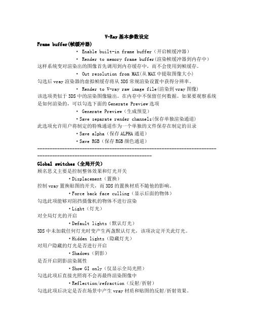
V-Ray基本参数设定Frame buffer(帧缓冲器)· Enable built-in frame buffer(开启帧缓冲器)· Render to memory frame buffer(渲染帧缓冲器到内存中)这样系统变对渲染出的图像首先调用到内存缓存中,而不会使用到帧缓存。
· Out resolution from MAX(从MAX中提取图像大小)勾选后vray渲染器的虚拟帧缓存将从3DS常规渲染设置中获得分辨率。
· Render to V-ray raw image file(渲染到vray图像)该选项类似于3DS中的渲染图像输出。
在内存中不保留任何数据。
如果要观察系统是如何渲染的,可以勾选下面的Generate Preview选项· Generate Preview(生成预览)·Save separate render channels(保存单独渲染通道)此选项允许用户将制定的特殊通道作为一个单独的文件保存在制定的目录·Save a lpha(保存ALPHA通道)·Save RGB(保存RGB颜色通道)----------------------------------------------------------------------------------------------------------------------Global switches(全局开关)顾名思义主要是控制整体效果和灯光开关·Displacement(置换)控制vray置换贴图的开关,而3DS的置换材质不随他的影响。
·Force back face culling(显示后面的物体)勾选此项能够对阻挡摄像机的物体不进行渲染·Light(灯光)对全局灯光的开启·Default lights(默认灯光)3DS中未加载任何灯光时变产生两盏默认灯光,该项决定开关此灯光。
L/D ratio L/D⽐Lamb wave 兰姆波Latent image 潜象Lateral scan 左右扫查Lateral scan with oblique angle 斜平⾏扫查Latitude (of an emulsion) 胶⽚宽容度Lead screen 铅屏Leak 泄漏孔Leak artifact 泄漏器Leak detector 检漏仪Leak testtion 泄漏检测Leakage field 泄漏磁场Leakage rate 泄漏率Leechs 磁吸盘Lift-off effect 提离效应Light intensity 光强度Limiting resolution 极限分辨率Line scanner 线扫描器Line focus 线焦点Line pair pattern 线对检测图Line pairs per millimetre 每毫⽶线对数Linear (electron) accelerator(LINAC) 电⼦直线加速器Linear attenuation coefficient 线衰减系数Linear scan 线扫查Linearity (time or distance)线性(时间或距离)Linearity, anplitude 幅度线性Lines of force 磁⼒线Lipophilic emulsifier 亲油性乳化剂Lipophilic remover 亲油性洗净剂Liquid penetrant examination 液体渗透检验Liquid film developer 液膜显像剂Local magnetization 局部磁化Local magnetization method 局部磁化法Local scan 局部扫查Localizing cone 定域喇叭筒Location 定位Location accuracy 定位精度Location computed 定位,计算Location marker 定位标记Location upon delta-T 时差定位Location, clusfer 定位,群集Location,continuous AE signal 定位,连续AE信号Longitudinal field 纵向磁场Longitudinal magnetization method 纵向磁化法Longitudinal resolution 纵向分辨率Longitudinal wave 纵波Longitudinal wave probe 纵波探头Longitudinal wave technique 纵波法Loss of back reflection 背⾯反射损失Loss of back reflection 底⾯反射损失Love wave 乐甫波Low energy gamma radiation 低能γ辐射Low-enerugy photon radiation 低能光⼦辐射Luminance 亮度Luminosity 流明Lusec 流西克。
【VRAY教程】V-RAY IMAGE SAMPLER参数详解在V-Ray中, image sampler所指的是对影像采样的演算⽅法,最终产⽣像素的阵列构成最终的图像。
V-Ray提供三种采样的演算法,所有都⽀援MAX标准的反锯齿滤镜。
你可以选择使⽤Fixed rate sampler,Adaptive DMC sampler或Adaptive subdivision sampler ─ 这三种选择。
影像采样器(Image sampler)1. Fixed固定采样对每个像素⽤相同数⽬的采样2. Adaptive DMC (⾃适应的DMC) 每个像素⽤可变数⽬的采样,根据每个像素的强度差异⽽定3. Adaptive subdivision (⾃适应细分) 这个采样器会把影像分割成⾃适应的格点,然后根据像素的强度来细分Antialiasing filter 反锯齿滤镜1. Fixed rate sampler 固定每像素的采样(内容简易,翻译略)2. Adaptive DMC sampler⾃适应的DMC采样器根据每个相邻的像素的强度来产⽣可变数⽬的采样的⼀种采样器以下图表视觉表⽰当使⽤Adaptive DMC sampler时,V-Ray是如何放置放置采样的。
⿊⾊的矩形呈现影像的像素,⽩⾊的点表⽰个别的采样。
在V-Ray的第⼀次运算(first pass)总是会放置最少的采样数⽬(根据Min. Subdivs这个参数决定数值),然后根据这次的采样的颜⾊⽐较,再下⼀次的计算(next pass)如果需要的话,添加更多的采样。
这样的采样器对于有⼤量细节的场景(例如VRayFur)或是有⼤量模糊效果(DOF, motion blur, glossy reflections等等)很有⽤,跟Adaptive subdivision sampler⽐较起来也⽤到⽐较少的记忆体Min subdivs 决定起始(最⼩)数⽬的采样通常你不需要将这个数值设定超过1,除⾮你场景中有很细的线,没有被正确地捕捉到,或是很快速移动的物件(当你开启motion blur时)。
Chapter6Volume Ray Casting on CUDAThe performance of graphics processors(GPUs)is improving at a rapid rate, almost doubling every year.Such an evolution has been made possible because the GPU is specialized for highly parallel compute-intensive applications,primarily graphics rendering,and thus designed such that more transistors are devoted to computation rather than caching and branch prediction units.Due to compute-intensive applications’high arithmetic intensity(the ratio of arithmetic operations to memory operations),the memory latency can be hidden with computations instead of using caches on GPUs.In addition,since the same instructions are executed on many data elements in parallel,sophisticatedflow control units such as branch prediction units in CPUs are not required on GPUs as much.Although the performance of3D graphics rendering achieved by dedicating graphics hardware to it far exceeds the performance achievable from just using CPU, graphics programmers had up to now to give up programmability in exchange for speed.They were limited to using afixed set of graphics operations.On the other hand,instead of using GPUs,images forfilms and videos are rendered using an off-line rendering system that uses general purpose CPUs to render a frame in hours because the general purpose CPUs give graphics programmers a lot offlexibility tocreate rich effects.The generality andflexibility of CPUs are what the GPU has been missing until very recently.In order to reduce the gap,graphics hardware designers have continuously introduced more programmability through several generations of GPUs.Up until 2000,no programmability was supported in GPUs.However,in2001,vertex-level programmability started to appear,and in2002,pixel-level programmability also started being provided on GPUs such as NVIDIA’s GeForce FX family and ATI’s Radeon9700series.This level of programmability allows programmers to have considerably more configurability by making it possible to specify a sequence of instructions for processing both vertex and fragment processors.However,accessing the computational power of GPUs for non-graphics appli-cations or global illumination rendering such as ray tracing often requires ingenious efforts.One reason is that GPUs could only be programmed using a graphics API such as OpenGL,which imposes a significant overhead to the non-graphics appli-cations.Programmers had to express their algorithms in terms of the inadequate APIs,which required sometimes heroic efforts to make an efficient use of the GPU. Another reason is the limited writing capability of the GPU.The GPU program could gather data element from any part of memory,but could not scatter data to arbitrary locations,which removes lots of the programmingflexibility available on the CPU.In order to overcome the above limitation,NVIDIA has developed a new hard-ware and software architecture,called CUDA(Compute Unified Device Architec-ture),for issuing and managing computations on the GPU as a data-parallel com-puting device that does not require mapping instructions to a graphics API[NVI07]. CUDA provides the general memory access feature,and thus,the GPU program is now allowed to read from and write to any location in memory on CUDA.In order to harness the power of the CUDA architecture,we need new design strategies and techniques that fully utilize the new features of the architecture. CUDA is basically tailored for data-parallel computations and thus is not well suited for other types of computations.Moreover,the current version of CUDA requires programmers to understand the specific architecture details in order to achieve the desired performance gains.Programs written without the careful attention to the architecture details are very likely to perform poorly.In this chapter,we explore the application of our streaming model,which was introduced in the previous chapter for the Cell processor,for the CUDA architecture. Since the model is designed for heterogeneous compute resource environment,it is also well suited for the CPU and CUDA combined environment.Our basic strategy in the streaming model is the same as in the case of Cell processor.We assign the work list generation to thefirst stage(CPU)and actual rendering work to the second stage(CUDA)with data movement streamlined through the two stages.The key is that the we carefully match the performances of the two stages so that two processes are completely overlapped and no stage has to wait for the input from the other stage.Our scheme features the following.First,we essentially remove the overhead caused by traversing the hierarchical data structure by overlapping the empty space skipping process with the actual rendering process.Second,our algorithms arecarefully tailored to take into account the CUDA architecture’s unique details such as the concept of warp and local shared memory to achieve high st, the ray casting performance is1.5times better than that of the Cell processor with only a third lines of codes of the Cell processor and15times better than that of Intel Xeon processor.6.1The CUDA Architecture OverviewThe CUDA(Compute Unified Device Architecture)hardware model has a set of SIMD multiprocessors as shown in Figure6.1.Each multiprocessor has a small local shared memory,constant cache,texture cache and a set of processors.At any given clock,every processor in the multiprocessor executes the same instruction.For example,NVIDIA Geforce8800GTX architecture is comprised of16multiprocessors. Each multiprocessor has8streaming processors for a total of128processors.Figure6.2shows the CUDA programming model.CUDA allows programmers to use C-language to program it instead of graphics APIs such as OpenGL and Direct3D.In CUDA,the GPU is a compute device that can execute a very high number of threads concurrently.The batch of threads is organized as a grid of thread blocks as shown in the Figure6.2.A thread block is a group of threads that can synchronize and efficiently share data through the local shared memory. One or more thread blocks are dispatched to each multiprocessor and executed using time sharing.Blocks are further organized into a grid.However,threads in different blocks can not communicate and synchronize with each other.In fact,Figure6.1:CUDA Hardware Architecture[NVI07]. synchronization mechanism is provided only to the threads in the same block,and thus,the correctness of any other communication attempts is not guaranteed because there is no mechanism that can determine the order of the threads executions in the case.This block independence makes CUDA scalable architecture because we can process more blocks in parallel as we add more processing units although it reduces programmingflexibility.As the memory and registerfile in a multiprocessor are shared by one or more blocks of a large number of threads,there is a limit in how many threads and blockscan be launched,depending on how much resources each thread and block requires.Figure6.2:CUDA Programming Model[NVI07].It is important to optimize the resource usage per thread so that more threads and blocks can be launched because as more threads get available there is a better chance that memory latency can be hidden.It is also important to efficiently use memory hierarchy of CUDA to achieve high performance.The shared memory in each multiprocessor provides more than two orders of magnitude faster access to data than what the device memory does, therefore it is important to utilize the shared memory.The best way is to pre-load data that is frequently accessed in the program onto the shared memory before it is used.Another important aspect of the current version of CUDA is the concept of warps.A warp is a SIMD group of threads,which constitute the unit of threads that a thread scheduler for a multiprocessor periodically switches to maximize the computational unit usage.If a warp of threads can not progress any more for some reason,then the scheduler replaces the current one with another warp that was waiting in the threads pool.A block of threads is typically comprised of a few warps.If the threads in a warp execute different instructions or their memory accesses cause bank conflicts,then the execution of the threads in the warp will be serialized,which will cause significant performance degradation.Thus,it is very important to take the concept of warp into consideration when programming for CDUA so that we can fully take advantage of the simultaneous computations of the multiprocessor.6.2CELL v.s.CUDATable6.1compares the two different architectures,Cell processor and CUDA, with a traditional CPU architecture in several categories.The main feature of Cell processor is that it provides more general parallel programming models than CUDA, making it a better choice for more general applications.For example,CUDA can not implement a streaming model on the chip,where a group of threads produce data and another group of threads consume the data for a certain processing at one kernel launch,while Cell can support that streaming programming model.However, CUDA provides much easier parallel programing model than Cell.For example,ourported code of the core volume rendering function for the Cell processor has more than3times as many lines as that of CUDA.Cell B.E.CUDA CPU Programming model SPMD,MPMD SPMD SPSD Simultaneous Threads tens Thousands1 Programmability Difficult Medium EasyHandling Memory La-tency Pre-fetching andDouble BufferingMultithreading CacheFeature Various ParallelProgrammingModel Easier Parallel ProgrammingGeneral Pur-poseLimitation Explicit datamovement byprogrammers Limited Program-ming ModelLow Perfor-manceTable6.1:Comparison of three different architectures.In the context of volume rendering,besides the programmability and perfor-mance difference,another main difference of the two parallel architectures is that Cell processor provides more scalable support to large volume rendering because it uses main memory as a primary data storage.On the other hand,CUDA has to move data from main memory to graphics device memory which is usually smaller than main memory and because the data communication bandwidth is usually an order of magnitude slower than graphics memory bandwidth,it loses significantamount of performance once it begins communicating with main memory during run time.6.3Primary Work Decomposition and AllocationIn this section,we describe our primary work decomposition and allocation scheme for volume ray casting on CUDA.CUDAFigure6.3:Work decomposition and assignment on CUDA.A tile consists of x by y block of threads and is dispatched into one of the multiprocessors.Our work decomposition scheme is based onfine-grain task parallelism that achieves load balancing among the multiprocessors.In ray casting,the overall con-currency is obvious since we can compute each pixel value on the screen indepen-dently of all the other pixels.To take advantage of this fact,we divide the screeninto a grid of small tiles as we did in the case of Cell processor.A block of threads equal to the number of pixels on each tile will be allocated for the tile and the block of threads will be executed by a multiprocessor,independently of other blocks of threads.However,there are several significant details that are different than the case of Cell processor.First,the maximum size of the tile is determined by how much resource each thread requires.Since the registerfile and shared memory are shared by one or more blocks of threads,we can only launch as many threads as the resource allows.Second,the dimensions of the tile are carefully selected considering the concept of warp.Since the threads in a warp should share the work list to achieve high performance,we design the dimensions of the tile such that a warp of threads occupy a rectangular region with as equal dimensions as possible.In our implementation,we use a tile of4x32dimension with a4x4subtile sharing the work st,the assignment of each tile to a multiprocessor is done by the CUDA scheduler while we had to assign the tasks to the cores of the Cell processor.6.4Implementation of the Streaming ModelIn this section,we describe the implementation of our streaming model from the previous chapter on CUDA architecture.As in the case of Cell processor,we assign two optimization techniques,empty space skipping and early ray termination, to an appropriate hardware,and streamline the data movement between the stages in the model.Efficiently implementing these two acceleration techniques is veryimportant since it significantly affects the ray casting performance.6.4.1Stage1:Work List GenerationA general purpose processor is clearly a better candidate for efficiently travers-ing a hierarchical data structure.Furthermore,CUDA would have a substantial overhead in handling empty space skipping due to the concept of warp,in which a group threads,32in the current version of CUDA,have to execute the same instruction at any given clock cycle for high performance.The procedure for generating work lists is the same as in the case of Cell processor.Given a ray,a CPU traverses the hierarchical data structure along the ray direction and collects contributing ray segments traversing non-empty subvolumes. Each ray segment is characterized by the ray offset from the viewpoint and the length of the corresponding segment.The collected ray segments for all the pixels of a tile are concatenated and transferred to CUDA.We also employ the approximation technique used for Cell processor.However, for CUDA,there is another reason for using this technique.Due to the concept of warp,it is better for a group of threads to share the work lists than each thread in the same warp to run independently.Therefore,we only generate the list of contributing ray segments for every k×k-th pixel,rather than for every pixel.For example,our tile(thread block)dimensions are4×32and we choose every4×4-th pixel for the work list generation.The region(16threads)surrounded by the 4chosen pixels is half warp size,and we estimate the contributing ray segments forthe region by taking the union of the ray segments lists at the surrounding4corners. Then,CUDA uses the resulting list to render to all the pixels in the region of size k×k.Note that the current version of CUDA has a shared memory organized into 16banks and thus it is recommended that at least a half warp of threads executes the same instruction.kapproximationA TileFigure6.4:Approximation technique on CUDA.The main difference of implementing the streaming model from the case of the Cell processor is the method used to stream the data.While we have multiple chan-nels from thefirst stage(a PPE)to the second stage(SPEs)on the Cell processor because each SPE runs independently,we have only one channel to CUDA because CUDA does not allow the independent access to each multiprocessor.Therefore, we need a large streaming unit to move to all the multiprocessors at one kernel launch as illustrated in Figure6.5.In our implementation,our streaming unit is 32tiles(blocks),which will allocate2blocks of threads to each multiprocessor on the Geforce8800GTX with16multiprocessors.After launching32tiles of work on CUDA,the CPU starts getting the contributing lists for the next32tiles and waituntil the previous launch is completed.CPUContributingRay Segment List(Offset, Length)…CUDARendered imageFigure6.5:The streaming model for CUDA.Note that the streaming unit is a set of tiless compared to one tile in the case of Cell processor.6.4.2Stage2:RenderingCUDA is ideal for the actual rendering work since it was designed for compute-intensive parallel workloads.Thus,we naturally implement rendering and early ray termination on CUDA.Before the rendering starts,we pre-load all the work lists for the current tile into the shared memory since the shared memory provides data with the latency of L-1cache(1∼2cycles).The other procedures are the same as before.We perform reconstruction,shading,classification,andfinally compositing on the sample points along all the contributing ray segments.Thefinal image is transferred back into main memory after afinal kernel launch isfinished.Figure6.6:Load balance between CPU and CUDA.6.5Experimental ResultsTo evaluate the performance of our streaming model based implementation, we used the same four volumetric datasets and rendering mode used in the case of Cell processor.Please refer to Table5.1for the characteristics of the datasets.We used Geforce8800GTX with a ver1.0CUDA drivers with Intel core2duo processor throughout the evaluation.Wefirst demonstrate that our streaming model implemented on the CUDA environment removes the overhead of traversing the octree structure for empty space skipping by fully overlapping it with the actual rendering process.Figure6.6shows the processing time for CPU and CUDA on the four datasets.Processing time on the CPU is the time it takes to traverse the octree data structure to generate the contributing ray segments.The CUDA time is the time it takes to perform the actual rendering.Thisfigure shows that the empty space skipping time is completelyFigure6.8:Performance with respect to the screen size.Figure6.9:Performance comparison(CPU v.s.Cell v.s.CUDA). hidden.Figure6.7and6.8show that the performance of our implementation with respect to input volumetric size and output screen size.We compare the rendering performance on CUDA with the Cell B.E.3.2GHz and also Intel Xeon dual processor3GHz with SSE2.Figure6.9shows that the performance on CUDA consistently achieves15times better performance that that of Intel and1.5times better than that of Cell processor.Also,it is very likely that it will produce even better performance once its3-D texture unit is exposed in the later version of CUDA because we can utilize the texture cache unit in each multiprocessor.This results show that the new multi-core/many-core architectures can handlecompute and communication intensive applications such as volume ray casting in much more efficient way since in particular,the Xeon processor and the Cell proces-sor that we have used for the experiments do not have much difference in the number of transistors(286million and234million,respectively)and operate at about the same frequency(3GHz and3.2GHz,respectively).6.6ConclusionsIn this chapter,we explored the application of our streaming model,which was introduced in the previous chapter for Cell processor,for the CUDA architecture. Our scheme fully utilizes the heterogeneous compute resource environment by using both task parallelism(simultaneous processing of the optimization techniques on different types of cores)and data parallelism(rendering by thousands of threads).CUDA provides about1.5times better performance than Cell processor while the CUDA program has only a third of parallel code lines of that of Cell processor in our implementation.However,aside from other factors such as the number of transistors and price,CUDA has a scalability problem with data set size because it can only efficiently render a data set which canfit in graphics memory,while the Cell processor can handle as large data as main memory allows.The improvements in GPU performance andflexibility are likely to continue in the future and will allow programmers to write increasingly diverse and sophisticated programs that take advantage of the capabilities of the GPUs.There are emerging efforts that combine CPU and GPU into a single chip.However,we will needefficient algorithmic strategies to make use of the available heterogeneous compute resources.。