邦纳无线模块说明书
- 格式:pdf
- 大小:888.49 KB
- 文档页数:9

modbus无线数传模块功能与规格说明1.MODBUS无线数传模块功能介绍 (3)1.1模块功能 (3)1.2部分功能详情 (3)1.2.1核心功能 (3)1.2.1.1数传模块modbus地址 (3)1.2.1.2自组网 (4)1.2.1.3告警 (4)1.2.1.4安全 (4)1.2.1.5电源管理 (4)1.2.1.6Modbus功能特性 (4)2.规格说明 (4)1.modbus无线数传模块功能介绍1.1模块功能表1-1:模块功能模块功能核心功能无线通信功能频段可切换(例如:433/868 / 915MHz)数传模块modbus地址地址可设置主从机可配置模块可设为为master/slave自组网能够形成mesh网络波特率波特率可设置告警告警状态安全通信数据加密电源管理UPS电源1.2部分功能详情1.2.1核心功能1.2.1.1数传模块modbus地址数传模块modbus地址与接入设备modbus地址统一分配。
modbus无线数传模块modbus地址设置:通过硬件设置,如dip开关;1.2.1.2自组网slave模块上电后能与master模块自动组网,甚至可以为其它slave模块中继接入。
1.2.1.3告警提供相关告警信息(如掉电,设备故障等)1.2.1.4安全数传模块无线传输数据加密。
1.2.1.5电源管理设计UPS电源管理电路。
1.2.1.6Modbus功能特性Function code Function codes descriptions0x11Report slave id0x03Read Holding Registers0x06preset single register提供寄存器地址列表2.规格说明modbus无线数传模块相关指标具体如下:低功耗数据传输模式: RTURoHS端口数: 2(RS-232 、RS-485 )接口标准:RS-232:DB9针式,RS-485:2线(A+,B-,GND) modbus地址: 1-247IP65防护;电源续航能力 1天;通信延时:500ms温度:-20~80°C单跳传输距离:0-500m。

无线模块Smart Node N801 使用说明书一、产品简介 (3)二、性能特点 (3)三、应用范围 (3)四、技术参数 (4)五、外型尺寸及管脚定义 (5)一、产品简介超低功耗无线自组网技术,简称Smart Node。
当用户需要将产品接入互联网时,将原有设备或传感器通过标准串口接入Smart Node模块,用户只需完成本地串口通讯,其他联网事情都由Smart Node模块完成,大大提高了产品开发周期。
二、性能特点1、超低功耗:休眠电流2.5uA,深度休眠电流60nA;2、组网深度8级中继(9跳);3、依据发射功率不同有下列几款产品:型号发射功率速率距离N801A 1000 mw 9.6 kbps 7千米N801B 500 mw 9.6 kbps 4千米N801C 1500 mw 9.6 kbps 10千米4、12×262bytes数据缓冲区;5、支持跳频、固定频率两种工作模式;6、支持SmartNode协议传输、数据透明传输;7、网络结构:点对点、点对多点、多级中继8、接口支持:1路UART串口,2路I/O口,或4路I/O口,或4路10位A/D转换;可扩展接口RS-485,RS-232,USB,CF卡。
三、应用范围⏹无线传感器网络⏹温度、湿度、压力监控系统⏹安防监控系统⏹远程抄表系统⏹无线控制系统⏹无线导游系统⏹无线POS系统⏹无线数据采集⏹无线遥控、工业遥控⏹智能家居⏹智能建筑⏹智能交通⏹车辆管理⏹RFID射频识别⏹医疗和电子仪器仪表自动化控制⏹饭店无线点菜系统及智能无线PDA终端⏹航道浮标及野外临时场地的LED显示器⏹高速公路不停车自动收费系统工程⏹铁路、油田、码头及部队的数据通信⏹行车和起重机等的工业遥控⏹灯光无线智能控制⏹安防报警及煤矿井下人员考勤和定位四、技术参数五、外型尺寸及管脚定义本产品资料仅供参考。
产品细节的变更恕不另行通知,请向本公司确认。
实际功能的实现需由专业人员对产品进行适当的调试。


GatewayPro models for protocol conversion or web-based configuration Features2.4 GHz 900 MHz The SureCross™ wireless system is a radio frequency network with integra-ted I/O that can operate in most environments while eliminating the need for wiring runs. Systems are built around a Gateway, which acts as the wireless network master device, and one or more Nodes.•10 to 30V dc power input•Modbus serial interface and Ethernet interface•Site Survey analyzes the network’s signal strength and reliability •Frequency Hopping Spread Spectrum (FHSS) technology and Time Divi-sion Multiple Access (TDMA) control architecture combine to ensure reli-able data delivery within the unlicensed Industrial, Scientific, and Medical (ISM) band•Transceivers provide bidirectional communication between the Gateway and Node, including fully acknowledged data transmissionFor additional information, the most recent version of all documentation, and a complete list of accessories, refer to Banner Engineering's website, /surecross.ModelsWARNING: Not To Be Used for Personnel ProtectionNever use this product as a sensing device for personnel protection. Doing so could lead to seri-ous injury or death. This product does NOT include the self-checking redundant circuitry necessary toallow its use in personnel safety applications. A sensor failure or malfunction can cause either an ener-gized or de-energized sensor output condition.SureCross DX80 GatewayProP/N 131933 rev. E1/11/201201319331The SureCross DX80 Wireless NetworkThe SureCross DX80 wireless I/O network provides reliable monitoring without the burden of wiring or conduit installation. The SureCross wireless network can operate independently or in conjunction with a host system, PLC, and/or PC software.Each wireless network system consists of one Gateway and one or more Nodes. Devices ship with factory defined inputs and outputsthat may be all discrete, all analog, or a mix of discrete and analog I/O.GatewayNodeNodeFlexPower Nodeand Battery Supply ModuleThe SureCross DX80 network is a deterministic system—the network identifies when the radio signal is lost and drives relevant outputs to user-defined conditions. Once the radio signal is reacquired, the network returns to normal operation.SureCross DX80 Gateways and NodesA Gateway acts as the master device within each radio network, initiates communication and reporting with the Nodes, and controls the timing for the entire network.The Gateway also holds the configuration for the network. Every wireless network must have one Gateway that schedules communica-tion traffic and controls the I/O configuration for the network. A radio network contains only one Gateway, but can contain many Nodes.Similar to how a gateway device on a wired network acts as a “portal” between networks, the SureCross Gateway acts as the portal between the wireless network and the central control process.A Node is a wireless network end-point device used to provide sensing capability in a remote area or factory. The Node collects data from sensors and communicates the data back to the Gateway. Nodes are available in a wide variety of power or input/output options.Each Node device can be connected to sensors or output devices and reports I/O status to the Gateway.SureCross DX80 GatewayProThe SureCross DX80 GatewayPro combines, in one unit, the function of a SureCross DX80 Gateway with the ability to interface to Ether-net using Modbus/TCP or EtherNet/IP ™ protocols. The GatewayPro has a serial port as well as an industrial Ethernet port. There are two basic models of the GatewayPro: DX80P*T6* and DX80P*A6*.•DX80P*T6*. The 'T6 model acts as a protocol converter only, offering the Modbus/TCP or EtherNet/IP communication protocols.•DX80P*A6*. The 'A6 model includes DX80 wireless network configuration, Modbus RTU master, Modbus/TCP client/server, Script Basic, e-mail, data logging, and trending.Connect a GatewayPro to a host system using the industrial Ethernet connection on the DX80 GatewayPro. To connect the GatewayPro directly to the host system without using an Ethernet switchbox/hub, some host systems may require a crossover cable.By default, the GatewayPro is configured to use Modbus/TCP server. To use EtherNet/IP, connect the GatewayPro to a managed switch.For more information, see SureCross Wireless I/O Product Manual or Host Configuration Manual .SureCross DX80 GatewayPro - tel: 763-544-3164P/N 131933 rev. ESureCross DX80 GatewayProLogging into the Web ConfiguratorThe SureCross™ Pro and DX83 Ethernet Bridge devices use an XML file to configure the network. To access the XML file, use any web browser set up for a direct connection to the Internet. If problems occur while connecting, verify the browser is not set to use a proxy server.When connecting to the Ethernet Bridge, GatewayPro, or MultiHop Pro directly from a host computer, a crossover Ethernet cable is required; when connecting through a switch or Ethernet hub, use a standard Ethernet cable.The factory default IP address for the devices is: 192.168.0.1.To change the device’s default IP address, first set up the host PC with an IP address different from the Ethernet Bridge, GatewayPro, or MultiHop Pro IP addresses. (Please refer to Banner document 133116 for detailed instructions on setting up the host computer’s network IP address.) For example, change the PC host IP address to: 192.168.0.2.After changing the host’s IP address, open a web browser and log into the Ethernet Bridge, GatewayPro, or MultiHop Pro by typing the IP.address in the browser location window: http://192.168.0.1log out, close the browser.For user-level access, enter the following as the user name and password.•User name: systemPassword: admin•For Admin-level access, enter the following as the user name and password:•User name: root•Password: sxiAdmin-level access allows administrators to set up system users and their passwords. Admin-level access is also required to change the IP address of the system.P/N 131933 rev. E - tel: 763-544-31643Wiring Diagrams5-pin Euro-Style HookupWiring the 5-pin Euro-style connector depends on the model and power requirements of the device. Connecting dc power to the commu-nication pins will cause permanent damage.1Brown 10 to 30V dc 2WhiteRS485 / D1 / B / +3Blue dc common (GND)4Black RS485 / D0 / A / –5GrayComms GndIndustrial Ethernet WiringUse the 4-pin industrial Ethernet connection to connect the radio network to an Ethernet-based host system.1White/Orange +Tx 2White/Blue +Rx 3Orange -Tx 4Blue-RxAdditional InformationFor additional information, including installation and setup, weatherproofing, device menu maps, troubleshooting, and a list of accesso-ries, refer to one of the following product manuals•SureCross Quick Start Guide: Banner part number 128185•SureCross Wireless I/O Network Manual: 132607•Web Configurator Manual (used with "Pro" and DX83 models): 134421Modbus Register TableSureCross DX80 GatewayPro - tel: 763-544-3164P/N 131933 rev. EDevice ConfigurationDIP Switch ChangesBefore making any changes to the DIP switch positions, disconnect the power. For devices with batteries integrated into the housing,remove the battery for at least one minute.DIP switch changes will not be recognized if power isn't cycled to the device.Accessing the DIP SwitchesTo access the DIP switches, follow these steps:1.Unscrew the four screws that mount the cover to the bottom housing.2.Remove the cover from the housing without damaging the ribbon cable or the pins the cable plugs into.3.Gently unplug the ribbon cable from the board mounted into the bottom housing. For integrated battery models (no ribbon cable) and Class I, Division 2 certified devices (ribbon cable is glued down), skip this step.4.Remove the black cover plate from the bottom of the device's cover.The DIP switches are located behind the rotary dials. After making the neces-sary changes to the DIP switches, place the black cover plate back into posi-tion and gently push into place. Plug the ribbon cable in after verifying that the blocked hole lines up with the missing pin. Mount the cover back onto the housing.DIP Switch Settings* Default configurationSureCross DX80 GatewayProP/N 131933 rev. E - tel: 763-544-31645Address ModeThe SureCross wireless devices may use one of two types of addressing modes: rotary dial addressing or extended addressing. In rotary dial address mode, the left rotary dial establishes the network ID and the right rotary dial sets the device ID. The wireless network is restricted to a maximum of 16 devices.Extended address mode uses a security code to "bind" Nodes to a specific Gateway. Bound Nodes can only send and receive informa-tion from the Gateway to which they are bound. In extended address mode, wireless networks may contain up to 48 radio devices. For more information on extended address mode, refer to the SureCross™ Wireless I/O Network product manual.The device ships in rotary dial address mode by default, with the DIP switch in the OFF position. To use extended address mode, change the DIP switch to the ON position.SpecificationsRadioRange900 MHz: Up to 4.8 kilometers (3 miles) *2.4 GHz: Up to3.2 kilometers (2 miles) *Transmit Power900 MHz: 21 dBm conducted2.4 GHz: 18 dBm conducted, less than or equal to 20dBm EIRP900 MHz Compliance (150 mW Radios)FCC ID TGUDX80 - This device complies with FCC Part 15, Subpart C, 15.247IC: 7044A-DX80092.4 GHz ComplianceFCC ID UE300DX80-2400 - This device complies with FCC Part 15, Subpart C, 15.247ETSI/EN: In accordance with EN 300 328: V1.7.1(2006-05)IC: 7044A-DX8024Spread Spectrum TechnologyFHSS (Frequency Hopping Spread Spectrum)Antenna ConnectionExt. Reverse Polarity SMA, 50 OhmsMax Tightening Torque: 0.45 N·m (4 in·lbf)Link TimeoutGateway: ConfigurableNode: Defined by Gateway* With the 2 dB antenna that ships with the product. High-gain an-tennas are available, but the range depends on the environment and line of sight. To determine the range of your wireless network, perform a Site Survey.GeneralPower*Requirements: +10 to 30V dc (For European applica-tions: +10 to 24V dc, ± 10%). (See UL section below for any applicable UL specifications)Consumption: Less than 1.4 W (60 mA) at 24V dc HousingPolycarbonateWeight: 0.26 kg (0.57 lbs)Mounting: #10 or M5 (M5 hardware included)Max. Tightening Torque: 0.56 N·m (5 in·lbf)InterfaceIndicators: Two bi-color LEDsButtons: TwoDisplay: Six character LCDWiring AccessOne 5-pin Euro-style male connector and One 4-pin fe-male industrial Ethernet connection* For European applications, power the DX80 from a Limited Pow-er Source as defined in EN 60950-1.CommunicationHardware (RS-485)Interface: 2-wire half-duplex RS-485Baud Rates: 9.6k, 19.2k (default), or 38.4k Modbus/TCP and EtherNet/IP4-wire Industrial Ethernet10/100 Mbps, full or half duplex, auto sensingSureCross DX80 GatewayPro - tel: 763-544-3164P/N 131933 rev. EData Format: 8 data bits, no parity, 1 stop bit ProtocolModbus RTUEnvironmentalRatingIEC IP67; NEMA 6; (See UL section below for any ap-plicable UL specifications)Operating Temperature−40 to +85° C (Electronics); −20 to +80° C (LCD) Operating Humidity95% max. relative (non-condensing)Radiated Immunity10 V/m, 80-2700 MHz (EN61000-6-2)Shock and VibrationIEC 68-2-6 and IEC 68-2-7Shock: 30g, 11 millisecond half sine wave, 18 shocksVibration: 0.5 mm p-p, 10 to 60 HzRefer to the SureCross™ DX80 Wireless I/O Network product manual, Banner p/n 132607, for installation and waterproofing in-structions. Operating the devices at the maximum operating condi-tions for extended periods can shorten the life of the device.Included with Device (GatewayPro Models)Included with Device Model Qty ItemMounting Hardware Kit BWA-HW-0014Screw, M5-0.8 x 25mm, SS4Screw, M5-0.8 x 16mm, SS4Hex nut, M5-0.8mm, SS4Bolt, #8-32 x 3/4", SSEthernet Crossover Cable BWA-EX2M1Ethernet Cable, M12 Industrial/RJ45, Crossover, 2 meterAntenna*BWA-9O2-C orBWA-2O2-C 1Antenna, 902-928 MHz, 2 dBd Omni, Rubber Swivel RP-SMA Male, or Antenna, 2.4 GHz, 2 dBd Omni, Rubber Swivel RP-SMA MaleSureCross Literature CD796851SureCross Literature CDSureCross Quick Start Guide1281851SureCross Quick Start GuideData sheet1* Internal antenna devices do not ship with this antennaAccessoriesEthernet Cables77669BWA-E2M Ethernet cable, RSCD RJ45 440, 2M78469BWA-E8M Ethernet cable, RSCD RJ45 440, 8M78467BWA-EX2M Ethernet cable, crossover, RSCD RJ45CR 440, 2MUse a crossover cable to connect the DX80 GatewayPro or DX83 Ethernet Bridge to a host system without using an Ethernet switchbox or hub. When using a switchbox or hub, use a straight cable.WarningsThe manufacturer does not take responsibility for the violation of any warning listed in this document.Make no modifications to this product. Any modifications to this product not expressly approved by Banner Engineering could void the user’s authority to operate the product. Contact the Factory for more information.SureCross DX80 GatewayProP/N 131933 rev. E - tel: 763-544-31647All specifications published in this document are subject to change. Banner reserves the right to modify the specifications of prod-ucts without notice. Banner Engineering reserves the right to update or change documentation at any time. For the most recent version of any documentation, refer to our website: . © 2006-2010 Banner Engineering Corp. All rights reserved. Antenna InstallationAlways install and properly ground a qualified surge suppressor when installing a remote antenna system. Remote antenna configura-tions installed without surge suppressors invalidate the manufacturer's warranty.Always keep the ground wire as short as possible and make all ground connections to a single-point ground system to ensure no ground loops are created. No surge suppressor can absorb all lightning strikes. Do not touch the SureCross™ device or any equipment connec-ted to the SureCross device during a thunderstorm.Exporting SureCross RadiosIt is our intent to fully comply with all national and regional regulations regarding radio frequency emissions. Customers who want to re-export this product to a country other than that to which it was sold must ensure the device is approved in the destination country. A list of approved countries appears in the Agency Certifications section of the product manual. The SureCross wireless prod-ucts were certified for use in these countries using the antenna that ships with the product. When using other antennas, verify you are not exceeding the transmit power levels allowed by local governing agencies. Consult with Banner Engineering if the destination country is not on this list.Limited WarrantyBanner Engineering Corp. warrants its products to be free from defects in material and workmanship for one year following the date of shipment. Banner Engineering Corp. will repair or replace, free of charge, any product of its manufacture which, at the time it is returned to the factory, is found to have been defective during the warranty period. This warranty does not cover damage or liability for misuse, abuse, or the improper application of the Banner product.THIS LIMITED WARRANTY IS EXCLUSIVE AND IN LIEU OF ALL OTHER WARRANTIES WHETHER EXPRESS OR IMPLIED (IN-CLUDING, WITHOUT LIMITATION, ANY WARRANTY OF MERCHANTABILITY OR FITNESS FOR A PARTICULAR PURPOSE), AND WHETHER ARISING UNDER COURSE OF PERFORMANCE, COURSE OF DEALING OR TRADE USAGE.This Warranty is exclusive and limited to repair or, at the discretion of Banner Engineering Corp., replacement. IN NO EVENT SHALL BANNER ENGINEERING CORP. BE LIABLE TO BUYER OR ANY OTHER PERSON OR ENTITY FOR ANY EXTRA COSTS, EX-PENSES, LOSSES, LOSS OF PROFITS, OR ANY INCIDENTAL, CONSEQUENTIAL OR SPECIAL DAMAGES RESULTING FROM ANY PRODUCT DEFECT OR FROM THE USE OR INABILITY TO USE THE PRODUCT, WHETHER ARISING IN CONTRACT OR WARRANTY, STATUTE, TORT, STRICT LIABILITY, NEGLIGENCE, OR OTHERWISE.Banner Engineering Corp. reserves the right to change, modify or improve the design of the product without assuming any obligationsor liabilities relating to any product previously manufactured by Banner Engineering Corp.Contact UsFor more information: Contact your local Banner representative or Banner Corporate Offices around the world.Corporate Headquarters: Banner Engineering Corp. 9714 Tenth Ave. North, Mpls., MN 55441, Tel: 763-544-3164, , sensors@Europe: Banner Engineering Europe Park Lane, Culliganlaan 2F, Diegem B-1831 BELGIUM,Tel: 32-2 456 07 80, Fax: 32-2 456 07 89, , mail@Latin America: Contact Banner Engineering Corp. (US) or e-mail Mexico:mexico@; or Brazil: brasil@Asia:Banner Engineering China Shanghai Rep Office Rm. G/H/I, 28th Flr. Cross Region Plaza No. 899, Lingling Road, Shanghai 200030 CHINA, Tel: 86-21-54894500, Fax: 86-21-54894511, , sensors@Banner Engineering Japan Cent-Urban Building 305 3-23-15, Nishi-Nakajima Yodogawa-Ku, Osaka 532-0011 JAPAN, Tel:81-6-6309-0411, Fax: 81-6-6309-0416, www.bannerengineering.co.jp, mail@bannerengineering.co.jpBanner Engineering Int’l Incorporated Taiwan Rep. Office 8F-2, No. 308, Sec. 1, Neihu Rd. Taipei, Taiwan 114 Phone: +886 2 8751 9966 #15 | Fax: +886 2 8751 2966, , info@ - tel: 763-544-3164P/N 131933 rev. EBanner Engineering India Pune Head Quarters Office, No. 1001 Sai Capital, Opp. ICC Senapati Bapat Road, Pune 411016 INDIA, Tel: 91-20-66405624, Fax: 91-20-66405623, www.bannerengineering.co.in, india@。
无线模块使用说明书
一、产品概述
无线模块是一种便捷、高效的电子设备,采用无线通信技术,
使设备在无需布线的情况下进行数据传输和通信。
本文档旨在为用
户提供详细的无线模块使用说明,帮助用户快速了解和使用该产品。
二、产品特点
1. 高效便捷:无线模块采用无线通信技术,可以实现设备之间
的快速数据传输和通信,避免了繁琐的布线。
2. 稳定可靠:采用先进的无线通信技术,使数据传输更加稳定
可靠,减少了传输过程中的数据丢失率。
3. 灵活易用:无线模块与设备连接简单方便,只需要进行简单
的设置即可实现设备间的快速通信。
三、产品安装与连接
1. 确保所有设备都处于关机状态。
2. 将无线模块插入需要进行无线通信的设备的对应插槽中,并
确保插紧。
3. 打开设备电源,并确保无线模块的电源指示灯正常亮起。
4. 对无线模块进行必要的设置,如设置连接方式、配置网络参
数等。
四、使用方法
1. 网络连接
根据设备的需求,选择合适的连接方式,如Wi-Fi、蓝牙等。
2. 配置网络参数
根据实际情况,配置无线模块的网络参数,包括网络名称、密
码等,确保连接的网络能够正常工作。
3. 设备通信
配置完成后,设备之间即可通过无线模块进行数据传输和通信。
用户可根据实际需求,自行编写代码或使用相应的软件进行通信。
五、常见问题解决。

SW8000系列IEEE802.11 a/b/g 产品用户手册Verion 2.0目录第1章产品介绍 (1)第2章硬件安装 (2)2.1 安装固定设备 (2)2.2 给设备供电 (2)第3章设备的工作模式 (4)3.1 Access Point Mode (4)3.2 Access Point Client Mode (4)3.3 Wireless Routing Client Mode (4)3.4 Gateway Mode (4)3.5 Wireless Adapter Mode (5)3.6 Transparent Client Mode (5)3.7 Repeater Mode (6)第4章配置IP地址 (7)第5章基本控制界面说明 (10)5.1 登入控制界面 (10)5.2 LAN Setup 有线网设置 (10)5.3 WLAN Setup 无限网设置 (11)5.3.1 Basic 基本设置 (11)5.3.1.1 在AP模式下 (11)5.3.1.2 在工作站模式下(Client) (11)5.3.1.3 Wireless Routing Client (12)5.3.1.4 Wireless Routing Client和Gateway模式的设置 (13)5.3.1.4.1 WAN Setup 广域网设置 (13)5.3.1.4.2 NAT Setup (18)5.3.1.4.3 Control the Bandwidth Available (18)5.3.1.4.4 Dynamic DNS Setup (20)5.3.2 Security安全设置 (24)5.3.2.1 WEP 加密方式 (25)5.3.2.2 WPA-Personal 加密方式 (25)5.3.2.3 802.1x/RADIUS 加密方式 (26)5.3.2.4 WPA Enterprise 加密方式 (27)5.3.3 Advanced 高级设置 (29)5.3.4 Statistics 统计数字 (29)5.3.5 MAC Address Filtering MAC地址过滤 (30)5.4 STP Setup 生成树协议设置 (30)5.5 设置 SNMP (31)5.6 SNMP Trap (32)第6 章. SYSTEM TOOLS 系统工具 (33)6.1 Traceroute 路由查询 (33)6.2 Ping Watchdog ping监视狗 (33)6.3 Ping Utility Ping测试 (33)6.4 Auto-Reboot 自动重启 (33)6.5 Syslog 系统日志 (34)6.6 System Identity 系统身份 (34)6.7 System Clock 系统时间 (34)6.8 Reboot System 重启系统 (34)6.9 Change Password 修改密码 (34)6.10 Logout 登出 (34)第 7 章 Device Access Management (35)7.1 Telnet/SSH Setup (35)7.2 设置 WEB 模式 (37)第 8 章 Security Configuration (39)8.1 Packet filtering (39)8.2 使用 URL Filtering (42)8.3 配置Firewall (43)8.4 使用Firewall Log (45)第1章产品介绍Skywave SW8000 系列高性能无线网络 Access Point 专为企业和公共接入设计。

2012 - 2013 Specifier's Guide美国邦纳选型指南|PLC&HMI |光电传感器|工业安全产品|机器视觉|测量检测传感器||工业无线网络产品|工业智能指示灯|旋转编码器|激光读码器|年风雨历练 版图跨越全球美国邦纳工程国际有限公司,始建于1966年,历经近45年的风雨历练,已成为当今世界最大的工业控制器( PLC & HMI )、变频器、光电传感器、测量检测、安全产品、工业无线网络产品、机器视觉、工业智能指示灯和旋转编码器的专业制造商之一,在世界主要地区均设有世界一流的生产、销售及服务机构。
丰富的产品选择、迅速的交货期、强大的技术支持、同行业最强大的研发能力,所有这一切都确保了美国邦纳在光电领域中领先者的地位。
美国邦纳致力于为客户提供以传感为核心的综合自动化解决方案,以“创新和服务”为企业使命的美国邦纳工程公司,正凭借着世界一流的精英团队、贴心服务、优质产品、先进技术及战略性的眼光,为邦纳的新世纪版图拓展写就华彩篇章,为更多企业的发展壮大提供领先、可靠的控制和检测解决方案。
46传感器市场领导者为您的企业保驾护航过去的15年,在由第三方组织的工程师购买意向调查中,邦纳公司连续50次位于第一位。
而且“财富500强”的大多数公司的传感器也是选用的邦纳公司的产品,他们依靠着邦纳的产品顺利实现了可靠的自动化解决方案。
汽车、家电药品、食品……无论您的企业属于哪个行业,邦纳都有先进的技术、可靠的产品,帮助您实现企业生产的自动化,提高产品的生产效率和质量,为您的企业发展保驾护航。
丰富的产品线,值得您应需选择邦纳拥有超过15,000多种产品,拥有同行业内最完整的产品线,生产包括光电及超声波传感器,视觉传感器、机床安全产品、测量与检测传感器,并且可以为客户各种应用提供解决方案。
我们每天发运数千件产品,平均每3.5秒就有一个邦纳的产品被安装使用!无论您想检测或测量何种部件或材料,邦纳都可以为您提供合适的产品和解决方案。
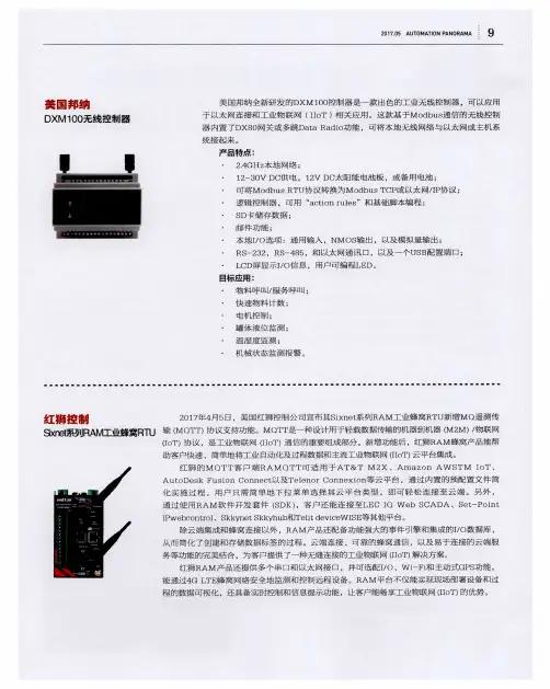
数据表DXM700-Bx 无线控制器是一种促进工业物联网(IIoT )应用的工业无线控制器。
作为通信网关,它使用蜂窝连接或有线以太网连接将本地串行端口、本地I/O 端口和本地ISM 电台设备连接到互联网。
•高性能无线通信-使用Sure Cross ® DX80无线网关或支持900MHz 或2.4GHz ISM 频段的多跳电台进行远距离通信。
•灵活且可定制-具备操作规则和ScriptBasic 编程的扩展型内部逻辑控制器,能够开发简单或复杂的解决方案,来处理、记录和控制与多个无线电台及传感器的数据。
•改善速度和内存-升级了内部处理器,支持使用2850个32位整数寄存器、2000个浮点寄存器和1050个非易失性32位整数寄存器;扩展了ScriptBasic 编程能力,可以更快地处理脚本,并能够使用脚本建立更复杂的解决方案•外部通信-蜂窝调制解调器互联网连接•尺寸紧凑-尺寸减小70毫米,从而减少DIN 导轨上占用的空间•简单Sourcing 输出-四路PNP 输出(在30 V DC 时最大为100 mA )可用于本地触发器•行业兼容性-自动化协议包括Modbus/TCP 、Modbus RTU 和EtherNet/IP ™,用于PLC 、HMI 或其他本地主机之间的通信。
•可定制的警报-为警报和提醒提供安全的电子邮件•数据记录到可移动的SD 卡或通过电子邮件发送•带有LCD 和LED 指示灯的交互式可编程用户界面•工业标准的RS-485、以太网和USB 通信端口型号B1 =电台配置B1基本DXM700-用于数据汇总的Modbus控制器传感器和无线网络电源:12-30 V DC通信:RS-485,二级RS-485 输出:四路PNPR1 = 900 MHz,1 W PE5高性能电台(北美)R2 = 900 MHz,1 W HE5多跳数传电台(北美)R3 = 2.4 GHz, 65 mW PE5性能电台(全球)R4 = 2.4 GHz, 65 mW HE5多跳数传电台(全球)R5 = 900 MHz,65 mW HE5L多跳数传电台(用于M-GAGE网络)PTL = 预先编程的DXM700,用于拾取指示灯集成(无电台)B2 =用于数据汇总的Modbus控制器传感器和无线网络电源:12-30 V DC通信:RS-485,二级RS-485 输出:四路PNP连接:管式插孔电源接口一些示例型号包括但不限于:蜂窝通信-控制器只接受邦纳LTE (美国)和GSM (美国以外)调制解调器。
Boost your existing WiFiOverviewNETGEAR AC1200 WiFi Range Extender boosts your existing network range, delivering AC dual band WiFi up to 1200 Mbps. The700mW high-power design provides ultimate range, while the dual-core processor enables maximum WiFi performance. It works with any standard WiFi router & is ideal for HD video streaming & gaming. Get the connectivity you need for iPads®, smartphones, laptops & more.• Dual band WiFi up to 1200 Mbps• 700mW high-power design for ultimate range • Dual-core processor for max WiFi performanceRANGEDUAL BAND AC1200AC1200 WiFi Range Extender—802.11ac Dual Band GigabitData SheetEX6200Blazing Fast CPUPowerful dual-core ARM A9 processor enables maximum WiFi throughput at Gigabit speed.Wireless PrintingPrint documents & photos to any USB printer connected to the WiFi Range Extender.5 Gigabit Ethernet PortsConnect up to 5 wired devices likeBlu-ray® players, game consoles, smart TVs or streaming players to your WiFi network.Next Generation WiFiCreate faster dual band WiFi access with 802.11ac technology up to 1200 Mbps.READYSHARE® USBWirelessly share & access USB storage connected to the USB 3.0 port.BEAMFORMING +Focuses WiFi signals directly to wireless devices for more reliable connections.FastLane ™ TechnologyUse both WiFi bands to establish one super high-speed connection; ideal for HD streaming & gaming.Ultimate Range700 mW high-power amplifiers & high-gain 5dBi antennas for maximum WiFi coverage.Existing WiFiSometimes your router does not provide the WiFi coverage you needExtenderBoosts the range of your existing WiFi & creates a stronger signal in hard-to-reach areasNetwork ConnectionsGigabit Ethernet portsPower on/o buttonConnect to powerStand for vertical placement (included)AC1200 WiFi Range Extender—802.11ac Dual Band Gigabit Data SheetEX6200 WiFi Analytics AppHow strong is your WiFi signal? Use the NETGEAR WiFi Analytics app & get advanced analytics to optimize your existing or newly extended WiFi network. Check your network status, WiFi signal strength, identify crowded WiFi channels & much more!Here’s what you can do with the WiFi Analytics App!• Get a network status overview• Check WiFi signal strength• Measure WiFi channel interference• Keep track of WiFi strength by location• and more...Scan to install appThis product is packaged with a limited warranty, the acceptance of which is a condition of sale. Warranty valid only when purchased from a NETGEAR authorized reseller.* 24/7 basic technical support provided for 90 days from date of purchase when purchased from a NETGEAR authorized reseller.1Works with devices supporting Wi-Fi Protected Setup™ (WPS).Data throughput, signal range, and wireless coverage per sq. ft. are not guaranteed and may vary due to differences in operating environments of wireless networks, including without limitation building materials and wireless interference. Specifications are subject to change without notice.The product may not be compatible with routers or gateways with firmware that has been altered, is based on open source programs, or is non-standard or outdated. ATTENTION: Due to EU law, the country settings must be identical to the country where the device is operating (important due to non-harmonised frequencies in the EU).For indoor use only. Valid for sale in all EU member states, EFTA states, and Switzerland.NETGEAR, and the NETGEAR Logo are trademarks of NETGEAR, Inc. Mac and the Mac logo are trademarks of Apple Inc. Any other trademarks herein are for reference purposes only. ©2015 NETGEAR, Inc.NETGEAR, Inc. 350 E. Plumeria Drive, San Jose, CA 95134-1911 USA, /supportD-EX6200-1AC1200 WiFi Range Extender—802.11ac Dual Band Gigabit Data SheetEX6200Package Contents• AC1200 WiFi Range Extender (EX6200)• Installation guide • Do More booklet • Power adapter • Stand• Two (2) 5dBi dual band detachable external antennasPhysical Specifications• Dimensions: 9.92 x 6.85 x 1.22 in (252 x 174 x 31 mm)• Weight: 0.67 lb (302 g)Warranty• For warranty details visit /about/warrantySecurity• WiFi Protected Access® (WPA/WPA2-PSK) and WEPStandards• IEEE® 802.11 b/g/n 2.4GHz • IEEE 802.11 a/n/ac 5GHz• Five (5) 10/100/1000 Ethernet ports with auto-sensing technology • USB 3.0 port• DLNA compatible Digital Media Server (DMS)Support• 24/7 basic technical support free for 90 daysEase of Use• CD-less setup—great for mobile devices • Push ‘N’ Connect using Wi-Fi Protected Setup® (WPS)1• Power on/off buttonSystem Requirements• 2.4 and/or 5GHz 802.11 a/b/g/n/ac WiFi router or gateway• Microsoft® Internet Explorer® 5.0, Firefox® 2.0 or Safari® 1.4 or Google Chrome 11.0 browsers or higherDual Core Processor。
无线移动模块TK-W-01规格使用说明V2.02019 深圳市同科联赢科技有限公司目录1概述 (2)2功能模块图 (4)3硬件结构说明 (5)4软件使用说明 (6)4.1登陆界面 (6)4.2无线设备状态 (6)4.2.1系统信息 (7)4.2.2 Internet配置 (7)4.2.3局域网 (7)4.3网络设置 (7)4.3.1无线外网设置 (8)4.3.2局域网设置 (8)4.4无线网络设置 (8)4.4.1无线连接设置 (9)4.4.2链接状态 (10)4.4.3无线扫描 (11)4.4.4漫游设置 (11)5设备规格参数 (12)5.1. 硬件规格/ Hardware Specification (12)5.2. 软件规格/ Software Specification (13)6 使用举例 (14)1概述无线移动模块TK-W-01是一款全新的产品,采用了嵌入式设计,其功能为有线(10/100M以太网络)和无线(WIFI)之间做一个智能转换,为有线终端设备加入到WIFI的网络提供了便捷的方式。
可以广泛的使用在矿山、工厂、隧道、林业、交通等应用场所。
一、功能说明1、将固定型IP设备转换成WIFI无线移动型IP设备2、转换完成的IP型设备,可以在多个WIFI信号之间自动切换,切换速度小于1SEC,当然,您的WIFI信号必须设置成相同的SSID和PASSWORD,但是信道可以不同。
二、连接方法说明:1、网口1和网口2是平行的,没有固定特指哪个固定连接位,在移动模块上面的两个网口,您可以任意连接;2、本模块总共有三个IP地址:局域网地址(管理地址,默认为192.168.169.1)此地址为本模块的管理地址,设置界面上称为局域网地址。
您可以自己定义,但是必须牢记,因为这个地址将来有两个用途,第一是通过本模块采用有线的方式直接连接到计算机上时,设置本模块,第二是通过网线与此模块连接的固定型Ip设备,其网关必须设置成这个地址。
用户指南内含NBN设备须知在尝试维修您的设备之前,请参考本指南以及封底的重要安全警告。
12快速入门指南 4将网络终端设备连接到您自己的设备 5维护您的设备 6电源装置 8备用电池更换说明 10主电源失灵怎么办 12电源装置指示灯及警报声 13故障排除检查清单 14网络终端设备指示灯 16常见问题 18重要安全警告 封底NBN用户指南您的NBN用户指南恭喜您通过自己选择的服务提供商接通全国宽带网络(NBN)。
通过NBN网络提供的服务有可能改变我们生活的方方面面,包括医护、教育、商业和政府服务。
随着宽带流量能力提高,宽带是发掘这一潜力的途径,也是本世纪的一项核心基础设施。
新的光纤连接让您可以使用到这一至关重要的通信基础设施。
本指南不但提供了如何确保您的NBN连接设备保持良好工作状态的信息,而且还概述了在系统工作不正常时怎么办。
.au3NBN 用户指南4在安装和检查您的设备之后,请阅读以下快速入门步骤,开始享用新的NBN 服务。
1 按照电话和互联网服务提供商指示,使用该服务的指定端口,将相容设备连接至网络终端设备。
2 如果您已安排通过话音(UNI-V )端口提供电话服务,就应该将电话机连接到网络终端设备上的指定有效话音(UNI-V )端口或现有电话插座。
您的电话和互联网服务提供商应该向您说明应该使用哪一个接口。
3 检查网络终端设备是否连接至电源装置。
4 检查电源装置是否插入主电源插座并且打开。
电源装置“系统状态”灯就会发出绿光。
网络终端设备“电源”和“光纤”灯都会发出绿光。
您的电话和互联网服务提供商同意为您提供的所有服务此时都应该工作正常。
网络终端设备光纤墙装插座电源装置您的网络终端设备背面有这样一排端口:如果您从服务提供商那里选择了通过话音(UNI-V)端口或数据(UNI-D)端口提供的电话服务,服务提供商就会告诉您如何连接电话机。
您的宽带服务将通过网络终端设备上的数据(UNI-D)端口提供。
您的服务提供商会告诉您他们对您的服务指定使用哪些数据(UNI-D)端口,并且告诉您如何连接这些服务的任何必要设备。
Setting the cutoff distance截止距离的调节Using a small screwdriver in the adjustment screw , adjust the cutoff distance until the threshold is reached and the green light indicator changes state.(If the indicator never comes ON, the background is beyond the maximum sensing cutoff and be ignored.)用一个小起子调节螺丝旋钮,调节截止距离,直到其临界值且绿色指示灯状态变化。
(如果指示灯没有on,则为背景超过了最大传感距离,且被忽略)Note the position of the rotating cutoff position indicator at this position.注意,旋转的该位置就是截止位置。
Then repeat the procedure, using the darkest target, placed in its most distant position for sensing. Adjust the cutoff so that the indicator is midway between the two positions.重复以上过程,在黑暗目标,用更远的距离进行感应,调节截至距离直到其在两个刻度的中间位置。
Sensing Reliability传感器可靠性For highest sensitivity, the sensor-to-object distance should be such that the object will be sensed at or near the point of maximum excess gain.为了获得高灵敏度,被检测物体的感应距离必须满足以下条件:该物体必须要在传感器的额定增益之内。
NETGEAR, Inc.350 East Plumeria Drive San Jose, CA 95134, USA (Etats-Unis)© NETGEAR, Inc., NETGEAR et le logo NETGEAR sont des marques commerciales de NETGEAR, Inc. Toutes les marques commerciales autres que NETGEAR sont utilisées à des fins de référence uniquement.Juillet 2021NETGEAR INTERNATIONAL LTD Floor 1, Building 3,University Technology Centre Curraheen Road, Cork, T12EF21, IrlandeGuide d’installationPoint d'accès Wifi Dual Band AC1200Modèle WAC1045Contenu de la boîte Présentation des voyantsAu cours de l’installation et de la configuration, les voyants du point d’accès peuvent s’allumer avec les couleurs suivantes :AlimentationVert continu . Le PA est prêt.Vert clignotant . Le PA démarre ou met à jour le firmware.WPSVert continu . Wi-Fi Protected Setup (WPS) est prêt pour utilisation. Par défaut, le voyant WPS est éteint.Vert clignotant . Quelqu’un a appuyé sur le bouton WPS du PA afin de permettre à son ordinateur ou appareil mobile compatible WiFi de rejoindre le réseau WiFi.WiFiVert continu . Une ou plusieurs radios WiFi fonctionnent.Vert clignotant . Une ou plusieurs radios WiFi envoient ou reçoivent du trafic.Réseauxlocaux 1 à 4Vert continu . Le port de réseau local détecte une liaison avec un appareil du réseau local.Vert clignotant . Le port de réseau local transmet ou reçoit des données.51. Connectez le câble Ethernet fourni avec le produit à l'un des ports Ethernet du PA.Vous pouvez utiliser l'un des quatre ports LAN du PA.2. Connectez l'autre extrémité du câble à un port de réseau local de votre routeur.REMARQUE : Ne connectez pas le PA à votre modem. Le PA doit être connecté à votre routeur.Le PA utilise un client DHCP activé par défaut. Presque tous les routeursfonctionnent comme serveurs DHCP , ce qui permet au PA de recevoir une adresse IP du routeur.3. Allumez le PA en appuyant sur le bouton Power On/Off (Alimentation).Étape 1. Connectez et allumez le PASchéma d’exemples de connexions IMPORTANT : Le point d’accès (PA) fournit une connectivité WiFi et LAN mais c'est un pont et non un routeur. Connectez le PA à un routeur connecté à un modem. Ne connectez pas le PA directement à un modem tel qu'un modem DSL ou câble.Etape 2. Connectez-vous au réseau WiFi du PAVous pouvez connecter un ordinateur ou appareil mobile compatible WiFi manuellement ou utiliser la méthode Wi-Fi Protected Setup (WPS).Méthode manuelle1. Ouvrez le logiciel utilitaire gestionnaire de connexions WiFi d’un appareilcompatible WiFi.Cet utilitaire recherche l'ensemble des réseaux WiFi disponibles.2. Recherchez et sélectionnez l’un des noms de réseau WiFi par défaut du PA (SSID),qui correspondent à NETGEAR_11N et NETGEAR_11AC .REMARQUE : Si vous ne pouvez pas trouver les SSID, appuyez sur le bouton WiFi On/Off (activation/désactivation du WiFi), patientez une minute et regardez si l’utilitaire affiche un SSID ou les deux.3. Saisissez la phrase d’authentification WiFi par défaut, à savoir sharedsecret .Votre appareil se connecte au réseau WiFi du PA.Méthode WPSSi votre appareil mobile compatible WiFi prend en charge le WPS, vous pouvez utiliser cette technologie pour rejoindre le réseau WiFi du AP .Pour obtenir de l'aide sur le bouton WPS de votre appareil, consultez les instructions ou l'aide en ligne fournies avec l'appareil concerné. Certains équipements plus anciens ne sont pas compatibles avec la fonction WPS.1. Appuyez sur le bouton WPS situé sur le panneau arrière du PA.2. Dans un délai de deux minutes, appuyez sur le bouton WPS ou cliquez sur lebouton WPS physique affiché sur l'écran de votre ordinateur ou appareil mobile.Votre appareil se connecte au réseau WiFi du PA.1Bouton WPS 2Bouton d'activation/désactivation du Wifi 3Ports LAN 1-44Bouton Reset (Réinitialisation)5Bouton On/Off (Alimentation)6Connecteur d'alimentation CCPrésentation du panneau arrière1Voyant d’alimentation 2Voyant WPS 3Voyant WiFi4Voyant de réseau local 15Voyant de réseau local 26Voyant de réseau local 37Voyant de réseau local 41234567A propos de la connexion à l’interface sur navigateur localIMPORTANT : Les étapes de connexion à l’interface du navigateur local de votre PA dépendent de la version du firmware qu’exécute votre PA.•Les étapes indiquées Étape 3. Connectez-vous à l’interface sur navigateur local et Etape 4. Recherchez un nouveau firmware s’appliquent uniquement si vous mettez à jour la version du firmware de votre PA avec la version 1.0.4.15 ou une version ultérieure, puis réinitialisez le PA avec ses paramètres par défaut.Si vous avez déjà réinitialisé le PA avec les paramètres par défaut après avoireffectué la mise à jour avec la version 1.0.4.15, et que vous mettez à jour le PA avec une version ultérieure à la version 1.0.4.15, il n’est pas nécessaire de réinitialiser à nouveau le PA avec ses paramètres par défaut.•Si votre PA exécute une version de firmware antérieure à la version 1.0.4.15 et que vous n’effectuez pas la mise à jour avec la version 1.0.4.15 ou une version ultérieure, reportez-vous à l’ancien guide d’installation, que vous pouvez télécharger en visitant le site https:///support/download/.•Nous conseillons vivement de télécharger le dernier firmware et de l’installer dès que possible.Visitez /support pour obtenir des réponses à vos questions et accéder aux derniers téléchargements.Vous pouvez également consulter notre communauté NETGEAR pour obtenir de bons conseils sur .Support et communautéPour les informations à propos de la conformité réglementaire, y compris la Déclaration de conformité pour l'UE, rendez-vous sur https:///about/regulatory/.Avant de brancher l’alimentation, reportez-vous au document de conformité légale.N’utilisez pas ce périphérique à l’extérieur.Applicable aux appareils 6 GHz uniquement : utilisez cet appareil en intérieur uniquement. L'utilisation de périphériques 6 GHz est interdite sur les plateformes pétrolières, les voitures, les trains, les bateaux et les aéronefs, à une exception : l'utilisation de ce périphérique est autorisée sur les grands avions volant à plus de 10 000 pieds d’élévation. L'utilisation d'émetteurs sur la bande 5,925 - 7,125 GHz est interdite pour le contrôle de systèmes d'aéronef sans pilote ou la communication avec ces systèmes.Règlementation et aspects juridiquesCes étapes s’appliquent uniquement si vous avez mis à jour la version du firmware de votre PA avec la version 1.0.4.15 ou une version ultérieure, puis réinitialisé le PA avec ses paramètres par défaut.Avant de commencer à utiliser votre PA, nous vous recommandons d’utiliser la fonction de mise à jour automatique du PA pour rechercher un nouveau firmware.1. Ouvrez un navigateur Web sur un appareil compatible WiFi disposant d’uneconnexion WiFi au PA (voir Etape 2. Connectez-vous au réseau WiFi du PA ) et saisissez ou dans le champ d’adresse.Une fenêtre de connexion s'affiche.2. Saisissez le nom d'utilisateur et le mot de passe du PA.Le nom d'utilisateur est admin . Le mot de passe est celui que vous avez indiqué sur la page de configuration initiale lors de votre première connexion à l’interface sur navigateur local (voir Étape 3. Connectez-vous à l’interface sur navigateur local ). Le nom d'utilisateur et le mot de passe sont sensibles à la casse.L'écran d'accueil s'affiche.3. Sélectionnez Administration > Firmware Update (Administration > Mise à jourdu micrologiciel).La page Mise à jour du firmware s'affiche.4. Cliquez sur le bouton Check (Vérifier).le PA détecte un nouveau firmware ; en cas de disponibilité, il affiche un message vous demandant si vous voulez le télécharger et l’installer.5. Pour télécharger et installer le nouveau firmware, cliquez sur le bouton Yes (Oui).Le PA localise le firmware, le télécharge et démarre la mise à jour.Une barre de progression indique la progression du chargement du firmware. La procédure de chargement du firmware prend plusieurs minutes. Une fois le chargement terminé, votre PA redémarre.AVERTISSEMENT : Pour éviter tout risque de corruption du micrologiciel (firmware), n'interrompez pas la mise à jour. Par exemple, ne fermez pas le navigateur, ne cliquez pas sur un lien et ne chargez pas de nouvelle page. N'éteignez pas le PA. Patientez jusqu’à ce que le PA termine le chargement dunouveau firmware et redémarre, et que le voyant d’alimentation cesse de clignoter et reste allumé en vert continu.6. Reconnectez-vous à l’interface sur navigateur local.L'écran d'accueil s'affiche. La version du firmware est indiquée dans le champ Firmware Version (version du firmware) du panneau d’informations du PA.Etape 4. Recherchez un nouveau firmwareCes étapes s’appliquent uniquement si vous avez mis à jour la version du firmware de votre PA avec la version 1.0.4.15 ou une version ultérieure, puis réinitialisé le PA avec ses paramètres par défaut.1. Ouvrez un navigateur Web sur un appareil compatible WiFi disposant d’uneconnexion WiFi au PA (voir Etape 2. Connectez-vous au réseau WiFi du PA ) et saisissez ou dans le champ d’adresse.Ces URL sont les mêmes que l’adresse IP 192.168.0.100. Une fenêtre de connexion s'affiche.2. Saisissez le nom d'utilisateur et le mot de passe du PA.Le nom d'utilisateur est admin . Le mot de passe par défaut est password . Le nom d'utilisateur et le mot de passe sont sensibles à la casse.La page de configuration initiale s'affiche. Cette page s’affiche uniquement lors de votre première connexion à l’interface utilisateur sur navigateur local.3. Sur la page de configuration initiale, procédez comme suit :• Définissez un nouveau mot de passe pour l’administrateur.•Activez la récupération du mot de passe et définissez des questions desécurité. Bien que cette opération soit facultative, nous vous recommandons d’activer la récupération du mot de passe.•Pour une meilleure sécurité, vous pouvez également définir de nouveaux noms de réseau WiFi (SSID) pour le réseau WiFi dans les bandes radio 2,4 GHz et 5 GHz et de nouvelles phrases d’authentification WiFi.Nous vous recommandons de laisser le PA obtenir son adresse IP du routeur de votre réseau (il s’agit du paramètre par défaut). Toutefois, si vous voulez utiliser une adresse IP statique pour le PA, vous pouvez le faire.4. Cliquez sur le bouton Apply (Appliquer).Les paramètres sont enregistrés.5. Si vous définissez un nouveau SSID et une phrase d’authentification, reconnectez-vous au PA à l’aide du nouveau SSID et de la phrase d’authentification.6. Reconnectez-vous à l’interface utilisateur sur navigateur local à l’aide de votrenouveau mot de passe.Vous pouvez à présent contrôler et gérer le PA.Étape 3. Connectez-vous à l’interface sur navigateur localConseils de dépannageLe tableau suivant fournit des conseils pour résoudre des problèmes simples que vous pouvez rencontrer. pour plus d'informations sur le dépannage, reportez-vous au chapitre Dépannage du manuel de l'utilisateur.ProblèmeCauseSolution possibleVous ne pouvez pas vousconnecter par WiFi au PA.Le voyant WiFi est éteint, ce qui indique que les radios WiFi sont désactivées.Vérifiez que les radios sont sous tension en appuyant sur le bouton WiFi On/Off (Marche/arrêt du WiFi).Vous utilisez peut-être de mauvais identifiants WiFi.Si vous n’avez pas modifié les SSID pardéfaut et la phrase d’authentification WiFi par défaut, vérifiez que vous vous connectez à NETGEAR_11N ou NETGEAR_11AC et que vous utilisez sharedsecret comme phrase d’authentification WiFi.Vous êtes trop loin du PA.Rapprochez-vous du PA et réessayez.Vous ne pouvez pas connecter plus de cinqclients WiFi au PA.Le PA ne trouve pas de serveur DHCP sur votre réseau.Vérifiez que l’un des ports de réseau local du PA est connecté à un routeur de votre réseau, afin que le PA puisse récupérer une adresse DHCP .Vous ne pouvez pas accéder à Internet.Plusieurs causes possibles.• Vérifiez que l’un des ports de réseau local du PA est connecté à un routeur de votre réseau.• Vérifiez que le routeur est connecté à votre modem.• Vérifiez que votre modem est connecté à la prise Internet.• Assurez-vous que votre fournisseur d'accès à Internet (FAI) ne connaisse pas de panne.Vous ne pouvez pas accéder au navigateur local après avoir mis à jour le firmware avec la version 1.0.4.15.Le nouveau firmware ne s’est pas installé complètement.1. Réinitialisez le PA avec ses paramètres par défaut en appuyant sur le bouton encastré Reset (Réinitialisation) sur le panneau arrière pendant au moins 10 secondes.2. Attendez que le voyant d’alimentation soit vert continu.3. Connectez-vous à l’interface sur navigateur local (voir Étape 3. Connectez-vous à l’interface sur navigateur local ).4. Reconfigurez le PA.Vous utilisez peut-être de mauvais identifiantsd’administrateur.Si vous n’avez pas encore modifié le mot de passe par défaut, saisissez password . Lenom d'utilisateur est admin . (Vous ne pouvez pas modifier le nom d’utilisateur.) Le nomd'utilisateur et le mot de passe sont sensibles à la casse.。
GatewayPro models for protocol conversion or web-based configuration Features2.4 GHz 900 MHz The SureCross™ wireless system is a radio frequency network with integra-ted I/O that can operate in most environments while eliminating the need for wiring runs. Systems are built around a Gateway, which acts as the wireless network master device, and one or more Nodes.•10 to 30V dc power input•Modbus serial interface and Ethernet interface•Site Survey analyzes the network’s signal strength and reliability •Frequency Hopping Spread Spectrum (FHSS) technology and Time Divi-sion Multiple Access (TDMA) control architecture combine to ensure reli-able data delivery within the unlicensed Industrial, Scientific, and Medical (ISM) band•Transceivers provide bidirectional communication between the Gateway and Node, including fully acknowledged data transmissionFor additional information, the most recent version of all documentation, and a complete list of accessories, refer to Banner Engineering's website, /surecross.ModelsWARNING: Not To Be Used for Personnel ProtectionNever use this product as a sensing device for personnel protection. Doing so could lead to seri-ous injury or death. This product does NOT include the self-checking redundant circuitry necessary toallow its use in personnel safety applications. A sensor failure or malfunction can cause either an ener-gized or de-energized sensor output condition.SureCross DX80 GatewayProP/N 131933 rev. E1/11/201201319331The SureCross DX80 Wireless NetworkThe SureCross DX80 wireless I/O network provides reliable monitoring without the burden of wiring or conduit installation. The SureCross wireless network can operate independently or in conjunction with a host system, PLC, and/or PC software.Each wireless network system consists of one Gateway and one or more Nodes. Devices ship with factory defined inputs and outputsthat may be all discrete, all analog, or a mix of discrete and analog I/O.GatewayNodeNodeFlexPower Nodeand Battery Supply ModuleThe SureCross DX80 network is a deterministic system—the network identifies when the radio signal is lost and drives relevant outputs to user-defined conditions. Once the radio signal is reacquired, the network returns to normal operation.SureCross DX80 Gateways and NodesA Gateway acts as the master device within each radio network, initiates communication and reporting with the Nodes, and controls the timing for the entire network.The Gateway also holds the configuration for the network. Every wireless network must have one Gateway that schedules communica-tion traffic and controls the I/O configuration for the network. A radio network contains only one Gateway, but can contain many Nodes.Similar to how a gateway device on a wired network acts as a “portal” between networks, the SureCross Gateway acts as the portal between the wireless network and the central control process.A Node is a wireless network end-point device used to provide sensing capability in a remote area or factory. The Node collects data from sensors and communicates the data back to the Gateway. Nodes are available in a wide variety of power or input/output options.Each Node device can be connected to sensors or output devices and reports I/O status to the Gateway.SureCross DX80 GatewayProThe SureCross DX80 GatewayPro combines, in one unit, the function of a SureCross DX80 Gateway with the ability to interface to Ether-net using Modbus/TCP or EtherNet/IP ™ protocols. The GatewayPro has a serial port as well as an industrial Ethernet port. There are two basic models of the GatewayPro: DX80P*T6* and DX80P*A6*.•DX80P*T6*. The 'T6 model acts as a protocol converter only, offering the Modbus/TCP or EtherNet/IP communication protocols.•DX80P*A6*. The 'A6 model includes DX80 wireless network configuration, Modbus RTU master, Modbus/TCP client/server, Script Basic, e-mail, data logging, and trending.Connect a GatewayPro to a host system using the industrial Ethernet connection on the DX80 GatewayPro. To connect the GatewayPro directly to the host system without using an Ethernet switchbox/hub, some host systems may require a crossover cable.By default, the GatewayPro is configured to use Modbus/TCP server. To use EtherNet/IP, connect the GatewayPro to a managed switch.For more information, see SureCross Wireless I/O Product Manual or Host Configuration Manual .SureCross DX80 GatewayPro - tel: 763-544-3164P/N 131933 rev. ESureCross DX80 GatewayProLogging into the Web ConfiguratorThe SureCross™ Pro and DX83 Ethernet Bridge devices use an XML file to configure the network. To access the XML file, use any web browser set up for a direct connection to the Internet. If problems occur while connecting, verify the browser is not set to use a proxy server.When connecting to the Ethernet Bridge, GatewayPro, or MultiHop Pro directly from a host computer, a crossover Ethernet cable is required; when connecting through a switch or Ethernet hub, use a standard Ethernet cable.The factory default IP address for the devices is: 192.168.0.1.To change the device’s default IP address, first set up the host PC with an IP address different from the Ethernet Bridge, GatewayPro, or MultiHop Pro IP addresses. (Please refer to Banner document 133116 for detailed instructions on setting up the host computer’s network IP address.) For example, change the PC host IP address to: 192.168.0.2.After changing the host’s IP address, open a web browser and log into the Ethernet Bridge, GatewayPro, or MultiHop Pro by typing the IP.address in the browser location window: http://192.168.0.1log out, close the browser.For user-level access, enter the following as the user name and password.•User name: systemPassword: admin•For Admin-level access, enter the following as the user name and password:•User name: root•Password: sxiAdmin-level access allows administrators to set up system users and their passwords. Admin-level access is also required to change the IP address of the system.P/N 131933 rev. E - tel: 763-544-31643Wiring Diagrams5-pin Euro-Style HookupWiring the 5-pin Euro-style connector depends on the model and power requirements of the device. Connecting dc power to the commu-nication pins will cause permanent damage.1Brown 10 to 30V dc 2WhiteRS485 / D1 / B / +3Blue dc common (GND)4Black RS485 / D0 / A / –5GrayComms GndIndustrial Ethernet WiringUse the 4-pin industrial Ethernet connection to connect the radio network to an Ethernet-based host system.1White/Orange +Tx 2White/Blue +Rx 3Orange -Tx 4Blue-RxAdditional InformationFor additional information, including installation and setup, weatherproofing, device menu maps, troubleshooting, and a list of accesso-ries, refer to one of the following product manuals•SureCross Quick Start Guide: Banner part number 128185•SureCross Wireless I/O Network Manual: 132607•Web Configurator Manual (used with "Pro" and DX83 models): 134421Modbus Register TableSureCross DX80 GatewayPro - tel: 763-544-3164P/N 131933 rev. EDevice ConfigurationDIP Switch ChangesBefore making any changes to the DIP switch positions, disconnect the power. For devices with batteries integrated into the housing,remove the battery for at least one minute.DIP switch changes will not be recognized if power isn't cycled to the device.Accessing the DIP SwitchesTo access the DIP switches, follow these steps:1.Unscrew the four screws that mount the cover to the bottom housing.2.Remove the cover from the housing without damaging the ribbon cable or the pins the cable plugs into.3.Gently unplug the ribbon cable from the board mounted into the bottom housing. For integrated battery models (no ribbon cable) and Class I, Division 2 certified devices (ribbon cable is glued down), skip this step.4.Remove the black cover plate from the bottom of the device's cover.The DIP switches are located behind the rotary dials. After making the neces-sary changes to the DIP switches, place the black cover plate back into posi-tion and gently push into place. Plug the ribbon cable in after verifying that the blocked hole lines up with the missing pin. Mount the cover back onto the housing.DIP Switch Settings* Default configurationSureCross DX80 GatewayProP/N 131933 rev. E - tel: 763-544-31645Address ModeThe SureCross wireless devices may use one of two types of addressing modes: rotary dial addressing or extended addressing. In rotary dial address mode, the left rotary dial establishes the network ID and the right rotary dial sets the device ID. The wireless network is restricted to a maximum of 16 devices.Extended address mode uses a security code to "bind" Nodes to a specific Gateway. Bound Nodes can only send and receive informa-tion from the Gateway to which they are bound. In extended address mode, wireless networks may contain up to 48 radio devices. For more information on extended address mode, refer to the SureCross™ Wireless I/O Network product manual.The device ships in rotary dial address mode by default, with the DIP switch in the OFF position. To use extended address mode, change the DIP switch to the ON position.SpecificationsRadioRange900 MHz: Up to 4.8 kilometers (3 miles) *2.4 GHz: Up to3.2 kilometers (2 miles) *Transmit Power900 MHz: 21 dBm conducted2.4 GHz: 18 dBm conducted, less than or equal to 20dBm EIRP900 MHz Compliance (150 mW Radios)FCC ID TGUDX80 - This device complies with FCC Part 15, Subpart C, 15.247IC: 7044A-DX80092.4 GHz ComplianceFCC ID UE300DX80-2400 - This device complies with FCC Part 15, Subpart C, 15.247ETSI/EN: In accordance with EN 300 328: V1.7.1(2006-05)IC: 7044A-DX8024Spread Spectrum TechnologyFHSS (Frequency Hopping Spread Spectrum)Antenna ConnectionExt. Reverse Polarity SMA, 50 OhmsMax Tightening Torque: 0.45 N·m (4 in·lbf)Link TimeoutGateway: ConfigurableNode: Defined by Gateway* With the 2 dB antenna that ships with the product. High-gain an-tennas are available, but the range depends on the environment and line of sight. To determine the range of your wireless network, perform a Site Survey.GeneralPower*Requirements: +10 to 30V dc (For European applica-tions: +10 to 24V dc, ± 10%). (See UL section below for any applicable UL specifications)Consumption: Less than 1.4 W (60 mA) at 24V dc HousingPolycarbonateWeight: 0.26 kg (0.57 lbs)Mounting: #10 or M5 (M5 hardware included)Max. Tightening Torque: 0.56 N·m (5 in·lbf)InterfaceIndicators: Two bi-color LEDsButtons: TwoDisplay: Six character LCDWiring AccessOne 5-pin Euro-style male connector and One 4-pin fe-male industrial Ethernet connection* For European applications, power the DX80 from a Limited Pow-er Source as defined in EN 60950-1.CommunicationHardware (RS-485)Interface: 2-wire half-duplex RS-485Baud Rates: 9.6k, 19.2k (default), or 38.4k Modbus/TCP and EtherNet/IP4-wire Industrial Ethernet10/100 Mbps, full or half duplex, auto sensingSureCross DX80 GatewayPro - tel: 763-544-3164P/N 131933 rev. EData Format: 8 data bits, no parity, 1 stop bit ProtocolModbus RTUEnvironmentalRatingIEC IP67; NEMA 6; (See UL section below for any ap-plicable UL specifications)Operating Temperature−40 to +85° C (Electronics); −20 to +80° C (LCD) Operating Humidity95% max. relative (non-condensing)Radiated Immunity10 V/m, 80-2700 MHz (EN61000-6-2)Shock and VibrationIEC 68-2-6 and IEC 68-2-7Shock: 30g, 11 millisecond half sine wave, 18 shocksVibration: 0.5 mm p-p, 10 to 60 HzRefer to the SureCross™ DX80 Wireless I/O Network product manual, Banner p/n 132607, for installation and waterproofing in-structions. Operating the devices at the maximum operating condi-tions for extended periods can shorten the life of the device.Included with Device (GatewayPro Models)Included with Device Model Qty ItemMounting Hardware Kit BWA-HW-0014Screw, M5-0.8 x 25mm, SS4Screw, M5-0.8 x 16mm, SS4Hex nut, M5-0.8mm, SS4Bolt, #8-32 x 3/4", SSEthernet Crossover Cable BWA-EX2M1Ethernet Cable, M12 Industrial/RJ45, Crossover, 2 meterAntenna*BWA-9O2-C orBWA-2O2-C 1Antenna, 902-928 MHz, 2 dBd Omni, Rubber Swivel RP-SMA Male, or Antenna, 2.4 GHz, 2 dBd Omni, Rubber Swivel RP-SMA MaleSureCross Literature CD796851SureCross Literature CDSureCross Quick Start Guide1281851SureCross Quick Start GuideData sheet1* Internal antenna devices do not ship with this antennaAccessoriesEthernet Cables77669BWA-E2M Ethernet cable, RSCD RJ45 440, 2M78469BWA-E8M Ethernet cable, RSCD RJ45 440, 8M78467BWA-EX2M Ethernet cable, crossover, RSCD RJ45CR 440, 2MUse a crossover cable to connect the DX80 GatewayPro or DX83 Ethernet Bridge to a host system without using an Ethernet switchbox or hub. When using a switchbox or hub, use a straight cable.WarningsThe manufacturer does not take responsibility for the violation of any warning listed in this document.Make no modifications to this product. Any modifications to this product not expressly approved by Banner Engineering could void the user’s authority to operate the product. Contact the Factory for more information.SureCross DX80 GatewayProP/N 131933 rev. E - tel: 763-544-31647All specifications published in this document are subject to change. Banner reserves the right to modify the specifications of prod-ucts without notice. Banner Engineering reserves the right to update or change documentation at any time. For the most recent version of any documentation, refer to our website: . © 2006-2010 Banner Engineering Corp. All rights reserved. Antenna InstallationAlways install and properly ground a qualified surge suppressor when installing a remote antenna system. Remote antenna configura-tions installed without surge suppressors invalidate the manufacturer's warranty.Always keep the ground wire as short as possible and make all ground connections to a single-point ground system to ensure no ground loops are created. No surge suppressor can absorb all lightning strikes. Do not touch the SureCross™ device or any equipment connec-ted to the SureCross device during a thunderstorm.Exporting SureCross RadiosIt is our intent to fully comply with all national and regional regulations regarding radio frequency emissions. Customers who want to re-export this product to a country other than that to which it was sold must ensure the device is approved in the destination country. A list of approved countries appears in the Agency Certifications section of the product manual. The SureCross wireless prod-ucts were certified for use in these countries using the antenna that ships with the product. When using other antennas, verify you are not exceeding the transmit power levels allowed by local governing agencies. Consult with Banner Engineering if the destination country is not on this list.Limited WarrantyBanner Engineering Corp. warrants its products to be free from defects in material and workmanship for one year following the date of shipment. Banner Engineering Corp. will repair or replace, free of charge, any product of its manufacture which, at the time it is returned to the factory, is found to have been defective during the warranty period. This warranty does not cover damage or liability for misuse, abuse, or the improper application of the Banner product.THIS LIMITED WARRANTY IS EXCLUSIVE AND IN LIEU OF ALL OTHER WARRANTIES WHETHER EXPRESS OR IMPLIED (IN-CLUDING, WITHOUT LIMITATION, ANY WARRANTY OF MERCHANTABILITY OR FITNESS FOR A PARTICULAR PURPOSE), AND WHETHER ARISING UNDER COURSE OF PERFORMANCE, COURSE OF DEALING OR TRADE USAGE.This Warranty is exclusive and limited to repair or, at the discretion of Banner Engineering Corp., replacement. IN NO EVENT SHALL BANNER ENGINEERING CORP. BE LIABLE TO BUYER OR ANY OTHER PERSON OR ENTITY FOR ANY EXTRA COSTS, EX-PENSES, LOSSES, LOSS OF PROFITS, OR ANY INCIDENTAL, CONSEQUENTIAL OR SPECIAL DAMAGES RESULTING FROM ANY PRODUCT DEFECT OR FROM THE USE OR INABILITY TO USE THE PRODUCT, WHETHER ARISING IN CONTRACT OR WARRANTY, STATUTE, TORT, STRICT LIABILITY, NEGLIGENCE, OR OTHERWISE.Banner Engineering Corp. reserves the right to change, modify or improve the design of the product without assuming any obligationsor liabilities relating to any product previously manufactured by Banner Engineering Corp.Contact UsFor more information: Contact your local Banner representative or Banner Corporate Offices around the world.Corporate Headquarters: Banner Engineering Corp. 9714 Tenth Ave. North, Mpls., MN 55441, Tel: 763-544-3164, , sensors@Europe: Banner Engineering Europe Park Lane, Culliganlaan 2F, Diegem B-1831 BELGIUM,Tel: 32-2 456 07 80, Fax: 32-2 456 07 89, , mail@Latin America: Contact Banner Engineering Corp. (US) or e-mail Mexico:mexico@; or Brazil: brasil@Asia:Banner Engineering China Shanghai Rep Office Rm. G/H/I, 28th Flr. Cross Region Plaza No. 899, Lingling Road, Shanghai 200030 CHINA, Tel: 86-21-54894500, Fax: 86-21-54894511, , sensors@Banner Engineering Japan Cent-Urban Building 305 3-23-15, Nishi-Nakajima Yodogawa-Ku, Osaka 532-0011 JAPAN, Tel:81-6-6309-0411, Fax: 81-6-6309-0416, www.bannerengineering.co.jp, mail@bannerengineering.co.jpBanner Engineering Int’l Incorporated Taiwan Rep. Office 8F-2, No. 308, Sec. 1, Neihu Rd. Taipei, Taiwan 114 Phone: +886 2 8751 9966 #15 | Fax: +886 2 8751 2966, , info@ - tel: 763-544-3164P/N 131933 rev. EBanner Engineering India Pune Head Quarters Office, No. 1001 Sai Capital, Opp. ICC Senapati Bapat Road, Pune 411016 INDIA, Tel: 91-20-66405624, Fax: 91-20-66405623, www.bannerengineering.co.in, india@。