
1N415GM中文资料
- 格式:pdf
- 大小:354.18 KB
- 文档页数:8
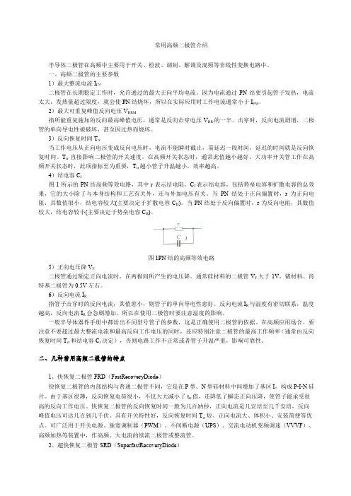
常用高频二极管介绍半导体二极管在高频中主要用于开关、检波、调制、解调及混频等非线性变换电路中。
一、高频二极管的主要参数1)最大整流电流I FM二极管在长期稳定工作时,允许通过的最大正向平均电流。
因为电流通过PN结要引起管子发热,电流太大,发热量超过限度,就会使PN结烧坏,所以在实际应用时工作电流通常小于I FM。
2)最大可重复峰值反向电压V RRM指所能重复施加的反向最高峰值电压,通常是反向击穿电压V BR的一半。
击穿时,反向电流剧增,二极管的单向导电性被破坏,甚至因过热而烧坏。
3)反向恢复时间T rr当工作电压从正向电压变成反向电压时,电流不能瞬时截止,需延迟一段时间,延迟的时间就是反向恢复时间。
T rr直接影响二极管的开关速度,在高频开关状态时,通常此值越小越好。
大功率开关管工作在高频开关状态时,此项指标至为重要,T rr越小管子升温越小,效率越高。
4)结电容C J图1所示的PN结高频等效电路,其中r表示结电阻,C J表示结电容,包括势垒电容和扩散电容的总效果,它的大小除了与本身结构和工艺有关外,还与外加电压有关。
当PN结处于正向偏置时,r为正向电阻,其数值很小,结电容较大(主要决定于扩散电容C D)。
当PN结处于反向偏置时,r为反向电阻,其数值较大,结电容较小(主要决定于势垒电容C B)。
J图1PN结的高频等效电路5)正向电压降V F二极管通过额定正向电流时,在两极间所产生的电压降。
通常硅材料的二极管V F大于1V,锗材料、肖特基二极管为0.5V左右。
6)反向电流I R指管子击穿时的反向电流,其值愈小,则管子的单向导电性愈好。
反向电流I R与温度有密切联系,温度越高,反向电流I R会急剧增加,所以在使用二极管时要注意温度的影响。
一般半导体器件手册中都给出不同型号管子的参数,这是正确使用二极管的依据。
在高频应用场合,要注意不要超过最大整流电流和最高反向工作电压的同时,还应特别注意二极管的最高工作频率(通常由反向恢复时间T rr和结电容C J决定),否则电路工作不正常或者管子升温严重,影响可靠性。


Switching USB Power Manager with PowerPath Control Offers Fastest Charge Time with Lowest Heat – Design Note 415Dave Simmons05/07/415IntroductionLithium-Ion and Lithium Polymer batteries are common in portable consumer products because of their relatively high energy density—they provide more capacity than other available chemistries within given size and weight constra ints. USB ba ttery cha rging is a lso becoming commonplace, as many portable devices require frequent interfacing with a PC for data transfer.As portable products become more complex, the need for higher capacity batteries increases, with a corresponding need for more a dvanced battery cha rgers. La rger batteries require either higher charging current or additional time to charge to their full capacity. Most consumers look for shorter charge times, so increasing the charge current seems obviously prefera ble, but increasing cha rge current presents two major problems. First, with a linear charger, increased current creates additional power dissipation (i.e., heat). Second, the charger must limit the current drawn from the 5V USB bus to either 100mA (500mW) or 500mA (2.5W) depending on the mode that the host controller has negotiated.PowerPath TM Controllers Deliver More Power to the System LoadThere are two methods commonly used to extract power from a USB port. The fi rst method uses a current limited battery charger directly between the USB port and the battery. This is referred to as a Battery Fed System because the system load is powered directly from the battery. Available power is given by I USB • V BAT because V BAT is the only volta ge a vailable to the system loa d. When the battery is low, nearly half of the available power can be lost within the linear battery charger element. In low battery voltage protection mode, as little as 5% of the available power may be usable.The second method develops a n intermedia te volta ge between the USB port and the battery. This intermedi-ate voltage bus topology is referred to as a PowerPath System. In PowerPath ICs, a current limited switch is placed between the USB port and the intermediate volt-Figure 1. LTC4088 PowerPath TopologyAll other trademarks are the property of their respective owners.© LINEAR TECHNOLOGY CORPORA TION 2007dn415f LT/TP 0507 409K • PRINTED IN THE USALinear Technology Corporation1630 M cCarthy Blvd., M ilpitas, CA 95035-7417(408) 432-1900 ● FAX: (408) 434-0507 ● 。