以太网测试仪ETS1000使用手册
- 格式:doc
- 大小:19.00 KB
- 文档页数:2

Quick Start Instruction ManualICT 1000 Level TransmitterNote: See Man 049 for complete installation, operation & maintenance instructions for ICT 1000 and associated RFM productsPSM WEEE Producer Registration No: WEE/HC0106WWDoc Ref: QS 049a 07/07/2015Burrell Road Industrial EstateHaywards Heath, West Sussex RH16 1TW, UK Tel: +44 (0)1444 410040 Fax: +44 (0)1444 410121 E -mail:*******************PSM INSTRUMENTATION LTDEC Declaration of ConformityThe products detailed within this manual meet the legal requirements of the applicable EC Directives.All EC Declaration of Conformities are available for download from our website .ConfigurationEach ICT 1000 is delivered with mechanical configuration (pressure cell range, mounting type and cable length) according to the customer order. Details for these can be back -referenced by contacting PSM with the unique instrument serial number engraved on each transmitter.For transmitters intended for use in analogue mode the measuring range (4 - 20mA) is normally configured according to the customer order. However this can easily be changed using a RS 485 <> Modbus converter and the PSM supplied ISS configuration software running on a Windows device. Refer to Man 053 for details.For transmitters intended for use in digital mode full application parameters will also have been factory set if requested. Again these may be easily changed or set up using the ISS software.1.11.2Prior to installation it is recommended that the following checks are made:∙ That any specific factory calibration is in accordance with the process parameters and tank height and that the ICT 1000 nominal range is suitable for the intended duty.∙ In analogue mode only, that the mA range is programmed correctly∙ In digital mode, that the application parameters such as SG, tank table, duty etc. are programmed correctly. This can be done using the PSM ISS software configuration tool.∙ Any instrument identification or tag number to ensure it is fitted in the correct location. The cable is factory fitted to the ICT ensure a pressure tight seal. and no attempt should be made to remove the cable gland.Instrument handlingBefore and during installation the following precautions should be taken∙ Do not touch the measurement cell of the ICT 1000 level transmitter∙ Do not apply mains voltage to any cable conductor∙ Ensure the ICT 1000 cable is free from damage and defectsSensor cableThe cable that is factory fitted to the transmitter is purpose designed for the application. It contains a nylon vent tube which provides an atmospheric reference for the sensor if construct-ed for a “gauge” measurement application. The end of the nylon tube has a short section of silicon tube fitted, which carries a sintered filter. This filter provides a pressure path, but pre-vents any moisture entering the vent tube and MUST remain in place. If the cable is shortened this filter must be transferred to the new cable end.Note that if the ICT 1000 is constructed as an “absolute” measuring device, then there is no requirement to vent the instrument cable to atmosphere. Precautions must still be taken however to prevent moisture ingress into the cable vent tube.The cable construction is of sufficient strength to enable the sensor to be directly suspended in deep wells and reservoirs. The outer sheathing is a special material suitable for continuous immersion in water,and many oils and chemicals. When handling the cable take particular care not to damage the outer sheathing.When a transmitter is suspended by its cable use a proprietary suspension cleat or wind three or four turns around a 100mm diameter pipe or drum. Where the cable is to be brought through the tank wall it is recommended that where possible this be done above the maximum fill line using a suitable compression fitting. (Available from PSM).Ensure the cable is not bent to a radius less than 50mm.MountingWhen mounting the unit ensure that suitable gaskets or sealants are employed to provide pressure tight seals. The sensor should not be mounted where it will be subject to excessive or continuous vibration, extreme temperature fluctuation or risk of mechanical damage.Secure the cable as required over longer runs to prevent mechanical abrasion if it moves.Do not secure the cable to any localised sources of high temperature heating such as steam coils used in heavy oil tanks.Cable is normally provided to the required length with the ends terminated as depicted above.The overall braid MUST be terminated in the entry gland of the termination enclosure to ensure it is earthed. Particular care should be taken to ensure that the 360° screen is maintained comply with the EMC standards of this unit.If, exceptionally, the cable has to be shortened, the nylon vent tube should be cut to a free length of approximately 20mm within the enclosure, it must be ensured that this tube is not blocked or otherwise restricted and the silicon tube containing the sintered filter must be re-fitted to the shortened length.The termination enclosure MUST be vented.Electrical connection ICT 1000 Analog and Digital cable identificationRed+ Power Analogue(4-20 mA) White+ Data Digital(Modbus)Black- Power Green- Data。

WFET-1000专变采集终端使用说明书范文目录123概述............................................................. ............................................................... .................-1-执行标准............................................................. ............................................................... .........-1-技术参数............................................................. ............................................................... .........-1-3.13.24外形与尺寸.............................................................. ...........................................................-1-主要技术指标.............................................................. . (2)功能描述............................................................. ............................................................... .........-3-4.14.24.34.4数据采集与统计分析.............................................................. ...........................................-3-状态监测与告警功能.........................................................................................................-4-存储功能.............................................................. ...............................................................-5-GPRS/CDMA无线数据通信功能.............................................................. .. (6)4.4.1GPRS模块主要特点............................................................. ........................................-7-4.4.2CDMA模块主要特点............................................................. .......................................-7-4.54.6停电上报功能(需要配后备电池)............................................................ ......................-8-负荷控制功能.............................................................. . (8)4.6.14.6.24.6.34.6.44.74.84.95遥控.............................................................. ..............................................................-8-电能量定值闭环控制.............................................................. ..................................-8-功率定值闭环控制.............................................................. ......................................-9-保电、剔除功 (11)软件升级功能.............................................................. .....................................................-11-对时功能.............................................................. .............................................................-11-后备电池(选配)............................................................ .. (11)调试............................................................. ............................................................... ...............-12-5.15.25.35.4键盘说明.............................................................. .............................................................-12-液晶显示.............................................................. .............................................................-12-界面操作.............................................................. .............................................................-12-调试步骤..............................................................13-6终端菜单操作指南............................................................. (14)6.16.26.3菜单格式说明.............................................................. .....................................................-14-菜单规范说明.............................................................. .....................................................-16-菜单工作流程.............................................................. .. (17)6.3.16.3.26.3.36.3.47轮循显示页.............................................................. ................................................-17-负控告警页.............................................................. ................................................-17-按键查询页.............................................................. ................................................-22-按键设置页.............................................................. (30)安装、调试注意事项............................................................. ..................................................-37-7.17.2安装用电现场管理终端.............................................................. ......................................-37-接线端子说明.............................................................. .. (38)长沙威胜信息技术有限公司i7.37.47.5电源选择.............................................................. .............................................................-39-连接RS-485通信线.............................................................. ...........................................-40-GPRS/CDMA通信调试.............................................................. . (41)7.5.1GPRS通信调试............................................................. ..............................................-41-7.5.2CDMA通信调试............................................................. .............................................-41-8维护............................................................................-42-8.18.28.38.48.58.691011终端日常维护的基本步骤.............................................................. ..................................-42-如何处理常见故障.............................................................. .............................................-42-更换表计时需要注意些什么.............................................................. ..............................-42-终端增加表计时应注意些什么.............................................................. ..........................-42-如何更换故障终端.............................................................. .............................................-43-如何进行远程升级和维护.............................................................. . (43)故障分析与排除.............................................................. .........................................................-44-包装、运输与储存.............................................................. ................................................-45-设备清单..............................................................-46-ii长沙威胜信息技术有限公司1概述请在使用本产品前仔细阅读各章节。

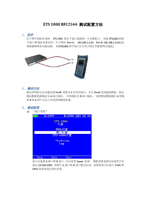
ETS 1000 RFC2544 测试配置方法1.拓扑以下图中的拓扑为例,ETS 1000 的2个端口连接到一台交换机上,因此ETS1000的两个端口IP地址设置在同一个子网内Port A:192.168.1.1/24 Port B: 192.168.1.2/24 (如果被测网络存在路由器,则ETS1000两个端口在不同子网并且配置网关地址)2.测试方法我们举例的方法为通过将PortB 设置为3层环回端口,并且PortA发送测试数据,指定测试数据的源地址为A端口地址,目的地址为B端口地址。
这样测试数据能在A到B 和B到A两个方向上传送得到测试结果。
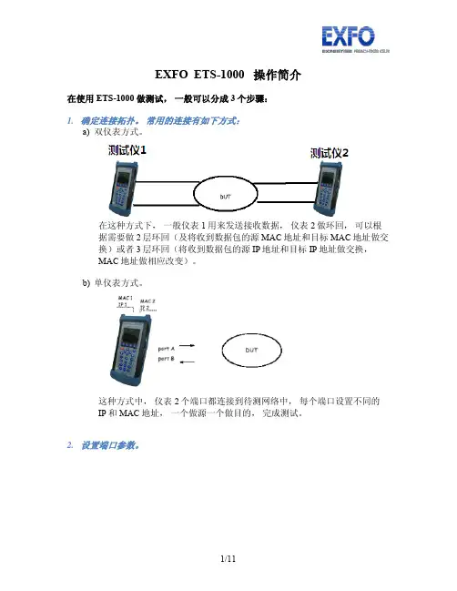
3.测试配置a)“接口设置”进入后选择A端口和B端口,并且设置Speed 选项,根据需要选择自动或者手动指定10/100/1000. 本例中A端口和B端口都为自动。
如果需要可以进入VLAN和MPLS的菜单进行相应设置b)接口设置完成后进入“网络设置”菜单,如之前拓扑设置A 地址192.168.1.1 和B地址192.168.1.2 (如果被测网络中有路由器则地址应该在不同子网,并设置相应网关地址)c)进入“tools”菜单,设置环回端口,进入菜单选择端口B,设置Layer 为3。
此时,端口B将交换所受到数据包的源地址和目的地址,以便把测试数据发回到A 端口。
d)返回主界面进入“tests“菜单,进入RFC 2544 测试设置e)进入“设置“f)进入“topology“菜单,设置TX和RX port 都为Ag)返回上一级进入“Header“,设置Src MAC 和IP 为A,Dst MAC和IP 为Bh)返回上一级进入“Frames“并选择需要测试的帧大小i)返回上一级进入“Throughput“,设置传输的速率“Rate”,测试时间“Trial,S”RFC2544 推荐为60秒以上j)返回并进入“Latency”,设置测试时间“trial,s”并设置测试速率“Rates”为Throughput。

操作手册EZPi-1000Rev. B, 06.2009FCC COMPLIANCE STATEMENTFOR AMERICAN USERSThis equipment has been tested and found to comply with the limits for a CLASS A digital device, pursuant to Part 15 of the FCC Rules. These limits are designed to provide reasonable protection against harmful interference when the equipment is operated in a commercial environment. This equipment generates, uses, and can radiate radio frequency energy and, if not installed and used in accordance with the instructions, may cause harmful interference to radio communications. Operation of this equipment in a residential area is likely to cause harmful interference in which case the user will be required to correct the interference at own expense.EMS AND EMI COMPLIANCE STATEMENTFOR EUROPEAN USERSThis equipment has been tested and passed with the requirements relating to electromagnetic compatibility based on the standards EN 55022:1998+A1:2000+A2:2003, CISPR 22 , Class A EN 55024:1998+A1:2001+A2:2003, IEC 61000- 4 Series EN 61000-3-2 / 2000 & EN 61000-3-3 / 1995. The equipment also tested and passed in accordance with the European Standard EN55022 for the both Radiated and Conducted emissions limits.EZPi-1000 SERIESTO WHICH THIS DECLARATION RELATESIS IN CONFORMITY WITH THE FOLLOWING STANDARDSEN55022 : 1998,CLSPR 22, Class A / EN55024 : 1998IEC 61000-4 Serial / EN61000-3-2 : 2000 / EN 6100-3-3 : 1995 / CFR 47, Part 15/CISPR 22 3rd Edition : 1997, Class A / ANSI C63.4 : 2001 / CNS 13438 / IEC60950-1 : 2001 / GB4943 : 2001 / GB9254 : 1998 / GB17625.1 : 2003 /EN60950-1 : 2001CAUTIONDanger of explosion if battery is incorrectly replacedReplace only with the equivalent type recommended by the manufacture.Dispose of used batteries according to the manufacturer’s instructions.Only use with power supply adapter model: WDS060240P (9A).Changes or modifications not expressly approved by the party responsible for compliance could void the user's authority to operate the equipment.Specifications are subject to change without notice.Bitte die Sicherheitshinweise sorgfältig lesen und für später aufheben.1. Die Geräte nicht der Feuchtigkeit aussetzen.2. Bevor Sie die Geräte ans Stromnetz anschließen, vergewissern Sie Sich, dass dieSpannung des Geräts mit der Netzspannung übereinstimmt.3. Nehmen Sie das Gerät bei Überspannungen (Gewitter) vom Netz. Das Gerät könntesonst Schaden nehmen.4. Sollte versehentlich Flüssigkeit in das Gerät gelangen, so ziehen sofort denNetzstecker. Anderenfalls besteht die Gefahr eines lebensgefährlichen elektrischen Schlags.5. Wartungs- und Reparaturarbeiten dürfen aus Sicherheitsgründen nur vonautorisierten Personen durchgeführt werden.6. Bei Wartungs- und Reparaturarbeiten müssen die Sicherheitsvorschriften derzuständigen Berufsverbände und Behörden unbedingt eingehalten werden.7. Bei Verletzungen unbedingt den Arzt aufsuchen und die gegebenenfalls diezuständigen Stellen benachrichtigen. Unterlassung kann zum Verlust derVersicherungsleistungen führen.Please read the following instructions seriously.1. Keep the equipment away from humidity.2. Before you connect the equipment to the power outlet, please check the voltage of thepower source.3. Disconnect the equipment from the voltage of the power source to prevent possibletransient over voltage damage.4. Don’t pour any liquid to the equipment to avoid electrical shock.5. ONLY qualified service personnel for safety reason should open equipment.6. Don’t repair or adjust energized equipment alone under any circumstances. Someonecapable of providing first aid must always be present for your safety7. Always obtain first aid or medical attention immediately after an injury. Never neglectan injury, no matter how slight it seems.安全须知请仔细阅读以下说明。

SIGNAL TEK™Cable Performance T esterI Gigabit PerformanceQualification – Test toIEEE 802.3 standardsI Selectable PerformanceT esting – qualify performanceof Data, Voice over IP, andIP Video applicationsI Performs Gigabit Ethernetlink establishment test in10 secondsI Data Monitoring to detectintermittent network problemsI Smart Autotest Functiondetects the presence of theSIGNAL TEK remote, activenetwork device or open endedcable and automatically runsthe appropriate test suiteI Intuitive Graphical UserInterface for fast andeasy operationI Internal and USBData Storage –store 20,000 tests internallyor unlimited on USB driveI Prints Easy-to-Read Pass/Fail Qualification ReportsSIGNALTEK™– High-Performance Gigabit Ethernet TestingSIGNALTEK™is the most cost-effective Gigabit Ethernet cableAutotest key to initiate tests from the remote end for one personoperation2.8Љ(7.1cm) 1⁄4VGA Color Display with backlighting for use in low light conditionMulti-color LEDs indicate link status,loopback mode,10/100 and Gigabit device detection,Autotest pass/fail,and battery conditionEasy-to-navigate user interfaceCompact design and soft over-mold sides fit well into any sized handContext sensitive softkeysSingle button cable testingQuick navigation key returns to Job Manager screenSingle button push for active network testing and monitoring Port status function detects 10/100 or Gigabit Ethernet devicesDisplays result for last autotest via red or green LED indicationSIGNAL TEK ™Standard KitCatalog No. 33-974I1 SIGNALTEK ™Near-end and remote-end handset IDEAL INDUSTRIES, INC.03/06Printed in U.S.A.ISO 9001:2000 QMSNo. 33-974SIGNALTEK ™OptionalPower Adapter – 4010-00-0136DESCRIPTION CAT NUMBER SIGNALTEK™ Cable Performance Tester 33-974Replacement cable accessory kit –Contains all original cables in SIGNALTEK™ kit 1219-91-0003RJ45 to 8 head alligator clipK-7920OPTIONALUniversal (120-240V) AC-DC power adapter (1)4010-00-0136。
ETS 1000 RFC2544 测试配置方法1.拓扑以下图中的拓扑为例,ETS 1000 的2个端口连接到一台交换机上,因此ETS1000的两个端口IP地址设置在同一个子网内Port A:192.168.1.1/24 Port B: 192.168.1.2/24 (如果被测网络存在路由器,则ETS1000两个端口在不同子网并且配置网关地址)2.测试方法我们举例的方法为通过将PortB 设置为3层环回端口,并且PortA发送测试数据,指定测试数据的源地址为A端口地址,目的地址为B端口地址。
这样测试数据能在A到B 和B到A两个方向上传送得到测试结果。
3.测试配置a)“接口设置”进入后选择A端口和B端口,并且设置Speed 选项,根据需要选择自动或者手动指定10/100/1000. 本例中A端口和B端口都为自动。
如果需要可以进入VLAN和MPLS的菜单进行相应设置b)接口设置完成后进入“网络设置”菜单,如之前拓扑设置A 地址192.168.1.1 和B地址192.168.1.2 (如果被测网络中有路由器则地址应该在不同子网,并设置相应网关地址)c)进入“tools”菜单,设置环回端口,进入菜单选择端口B,设置Layer 为3。
此时,端口B将交换所受到数据包的源地址和目的地址,以便把测试数据发回到A 端口。
d)返回主界面进入“tests“菜单,进入RFC 2544 测试设置e)进入“设置“f)进入“topology“菜单,设置TX和RX port 都为Ag)返回上一级进入“Header“,设置Src MAC 和IP 为A,Dst MAC和IP 为Bh)返回上一级进入“Frames“并选择需要测试的帧大小i)返回上一级进入“Throughput“,设置传输的速率“Rate”,测试时间“Trial,S”RFC2544 推荐为60秒以上j)返回并进入“Latency”,设置测试时间“trial,s”并设置测试速率“Rates”为Throughput。

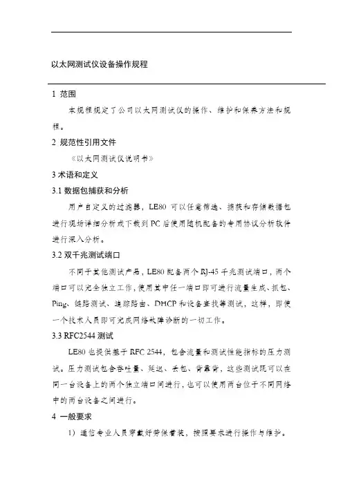
EXFO ETS-1000 操作简介在使用ETS-1000 做测试,一般可以分成3个步骤:1.确定连接拓扑。
常用的连接有如下方式:a)双仪表方式。
在这种方式下,一般仪表1用来发送接收数据,仪表2做环回,可以根据需要做2层环回(及将收到数据包的源MAC地址和目标MAC地址做交换)或者3层环回(将收到数据包的源IP地址和目标IP地址做交换,MAC地址做相应改变)。
b)单仪表方式。
这种方式中,仪表2个端口都连接到待测网络中,每个端口设置不同的IP和MAC地址,一个做源一个做目的,完成测试。
2.设置端口参数。
如图在设置界面设置网络参数和接口参数a)在网络设置中设置IP地址,子网掩码,网关地址参数b)在接口设置中设置MAC地址, 10, 100,1000M速率模式,以及是否要启用VLAN,以及VLAN ID3.设置测试类型a)RFC-2544 测试为业界衡量网络性能的主要标准,通过吞吐量,背对背,延迟和帧丢失等方面来衡量网络性能。
b)混合流量可以允许客户设置最多10条数据流,指定不同流的字节,速度等具体参数真实模拟网络流量,衡量网络性能。
i.在混合模式配置界面设置数据流的数量Stream 可选择1到10条数据流, Duration 设定数据流生成的时间ii.进入Topology 设定发送数据端口和接收数据端口,收发端口可以不同也可以相同iii.进入header 设置MAC地址和IP地址iv.进入Frame 设置每个数据流的大小v.最后在Rate 菜单中设置每个数据流的速率然后在混合流量->测试中开始测试,可以得到如下结果:c)BERT 误码率测试,允许发送特定的二进制码率,通过发送接收端的对比统计出误码的比特,比率等信息。
最后的测试实例有配置介绍。
d)数据包抖动,根据RFC4689的原理测试数据包在线路上的延迟差异,这种测试对延迟敏感的数据流如语音视频数据特别重要。
e)测试流量是用来生成流量拱数据包抖动测试使用,可以单端口发送接收或者从A端口发送的B端口两种模式。
以太网测试仪设备操作规程1 范围本规程规定了公司以太网测试仪的操作、维护和保养方法和规程。
2 规范性引用文件《以太网测试仪说明书》3术语和定义3.1数据包捕获和分析用户自定义的过滤器,LE80可以任意筛选、捕获和存储数据包进行现场详细分析或下载到PC后使用随机配备的专用协议分析软件进行深入分析。
3.2双千兆测试端口不同于其他测试产品,LE80配备两个RJ-45千兆测试端口,两个端口可以完全独立工作,使用其中任一端口即可进行流量生成、抓包、Ping、链路测试、追踪路由、DHCP和设备查找等测试,这样,即使一个技术人员即可完成网络故障诊断的一切工作。
3.3 RFC2544测试LE80也提供基于RFC 2544,包含流量和测试性能指标的压力测试。
压力测试包含吞吐量、延迟、丢包、背靠背,这些测试既可以在同一台设备上的两个独立端口间进行,也可以使用两台位于不同网络中的两台设备之间进行。
4 一般要求1)通信专业人员穿戴好劳保着装,按照要求进行操作与维护。
2)维护管理人员要努力学习专业技术,熟练掌握软交换系统及附属设备的原理及操作。
3)认真执行各项规章制度,做好设备维护,定时检查设备运行情况。
5 运行操作5.1 作业前的检查与准备检查设备外观无损坏、开机自检正常、电源指示灯及声音正常,设备清洁、关键接口处无杂质粘堵,准备所需要的配套工器具、掌握测试设备的基本情况。
5.2设备操作1)网络电话寻线功能:将带有水晶头的网线或电话线插到RJ45或RJ11寻线接口,将发射器开至寻线位置扫描指示灯闪亮,表示发射器正常工作,按住接收器的寻线按钮用探头查询需要的目标线缆。
2)网络线序校对功能:分别将网线两端水晶头插到发射器和接收器RJ45口,将发射器开至对线位置,采用自动扫描的方式,快速测试,将开关拨至对线位置,根据8个线序亮灯情况判断网线的线序是否正确。
3)普通金属线寻线功能:需要寻普通金属线的时候把鳄鱼夹连接在发射器上,通过鳄鱼夹将发射器和待寻线金属导线连接好,按住接收器的寻线按钮用探头查询需要的目标线缆,比较声音的大小及信号指示灯的亮暗程度,发出声音最响的同时指示灯最亮的一根线即为所要寻查的目标线缆。

ETS-1000使用手册2011年1月28日EXFO的ETS-1000是一款经济高效的手持式以太网分析仪,服务提供商可使用该仪器进行下一代运营商以太网服务的开通和安装。
ETS-1000具有两个完全独立的测试端口,可支持以下接口:10/100/1000Base-T、1000Base-LX和1000Base-ZX。
下图为仪器外观:一、基本功能介绍:1、按F1进入“Setup”设置界面,如下图所示:A)进入网络设置界面,可以设置各端口的IP、掩码、网关及DNS。
如下图所示:B)进入接口设置界面,可以设置各端口的速率(10/100/100/Automatic)、Autoneg(自动协商On/Off)、MAC地址、VLAN及VLANID等参数。
如下图所示C)ETS-1000设置为仪器基本设置,按出厂默认设置即可。
2、按F2进入“Tools”设置界面。
此界面可以测试以太网功能。
A)PING测试:Setup可以设置要PING的IP地址。
B)路由跟踪:可以测试IP 数据报访问目标所采取的路径。
C)DNS查找:输入网址,可以查找DNSD)ARP监测:是否有ARP欺骗。
如下图:E)TCP客户端:可测试访问网页是否正常。
TCP客户端设置:F)电缆测试:可测试电缆是否正常。
G)环回:可以设置环回端口的参数(可选项为Off, 1层,2层,3层,4层环回)。
如下图所示:3、按F3进入“Tests”设置界面。
A)RFC-2544标准测试:定义了四个测试:吞吐量,延迟,帧丢失率,背靠背。
如下图所示:(背靠背性能测试通过以最大帧速率发送突发传输流并测量无包丢失时的最大突发(burst)长度(总包数量)来测试被测设备的缓冲区容量。
)进入设置界面如下图所示:Topology参数:可以设置收发端端口。
若双仪表测试,则收发端为本端;若单仪表测试,则收发端为不同端口。
如下图所示:Header参数:设置Src MAC和IP及Dst MAC和IP。
以太网测试仪使用方法以太网测试仪(Ethernet tester)是一种专门用于测试以太网网络连接的仪器设备。
它可以帮助用户检测网络连接的质量、稳定性和速度,并提供有关网络故障的诊断信息。
下面将介绍如何正确使用以太网测试仪。
步骤一:设置测试仪1.将以太网测试仪的电源线插入电源插座,并确保仪器已开启。
2.连接测试仪的网线接口与要测试的以太网设备(如交换机、路由器或电脑)之间。
步骤二:选择测试模式1.在以太网测试仪上选择相应的测试模式。
常见的测试模式有连接测试、链路测试和速度测试等。
2. 根据需要选择测试的参数,如全双工或半双工、速率(10/100/1000 Mbps)等。
步骤三:进行测试1.进行连接测试:连接测试主要用于判断网络线缆的连通性。
在测试仪上选择连接测试模式,然后按下开始按钮。
测试仪会发送测试信号,如果连接是正常的,测试仪会显示连接成功。
2.进行链路测试:链路测试用于判断网络链路的质量和稳定性。
在测试仪上选择链路测试模式,然后按下开始按钮。
测试仪会发送测试信号,并检测链路中的错误、延迟和丢包等情况。
测试结束后,测试仪会显示详细的测试结果。
3.进行速度测试:速度测试用于测试网络传输速度。
在测试仪上选择速度测试模式,然后按下开始按钮。
测试仪会模拟网络传输,测量实际传输速度并显示在仪器屏幕上。
步骤四:分析测试结果1.根据测试仪显示的结果,分析网络连接的质量、稳定性和速度,判断是否存在问题。
2.如果测试结果显示错误、延迟或丢包等问题,可以尝试重新测试或检查网络设备和线缆是否连接正常。
3.如果测试结果显示传输速度低于预期,可能是网络带宽受限或其他因素导致。
可以进一步分析网络拓扑和设备配置,确定问题所在并进行解决。
步骤五:记录和报告1.记录测试仪显示的测试结果,包括测试日期、测试模式、参数设置和测试数据等。
2.如果需要,可以将测试结果生成报告,并保存供以后参考和分析。
总结:使用以太网测试仪可以帮助用户准确地测试和诊断以太网网络连接的问题。
Automotive Ethernet 1000Base-T1 TC9 measurement using VNA Application NoteProducts:ı R&S ®ZNB4 ı R&S ®ZN-Z51 ı R&S ®ZV-Z135 ıR&S ®ZV-Z192This application note is a systematic guide to help test engineers configure the Vector Network Analyzer in order to perform compliance test on Automotive Ethernet cables according to the Open Alliance TC9 standard.Note:Please find the most up-to-date document on our homepage https:///appnote/GFM323A p p l i c a t i o n N o t ea h m u d N a s e e f , J ör n P f e i f e r , A n d r e a D 'A q u i n o 9.2019 – G F 323_2eTable of ContentsTable of Contents1Introduction (3)2Test Setup (4)3Calibrating and Configuring the VNA for Measurement (5)3.1Characterization of the Calibration Unit (5)3.2Optional de-embedding of fixture boards (7)3.3Verification of VNA Calibration Accuracy (9)4Measurement and Results (12)4.1Measurement of Mixed-Mode S-Parameters (12)4.2Measurement of TDR based CIDM (Characteristic Impedance Differential Mode) (13)5Reference (15)6Ordering Information (16)Introduction1IntroductionThe evolution towards higher connectivity & electrification in the automotive industry is faster than ever before. More and more sensors are added to vehicles as the future of transportation moves towards higher level of automation. Reliability and quality of time critical communications between different systems are nowadays under the spotlight, and Ethernet cables have become the industry standard to support the network within the car.The Open Alliance TC9 compliance specification is regarded as a qualificationbenchmark for unshielded twisted pair (UTP) cables for Automotive Ethernet [1].This document contain electrical requirements and measurement specifications on1000BASE-T1 channel and components link segment type A (UTP). It shall be used as a standardized common scale for the evaluation of the RF properties for physical layercommunication channels to enable 1000BASE-T1 technology.The focus of this application note is to describe the method of performing compliance tests according to the TC9 specification for Ethernet cable testing. Chapter 2 describes the test setup required to perform measurements on 1000BASE-T1 coaxial cablesusing the four-port ZNB4 Vector Network Analyzer (VNA) from Rohde & Schwarz.Chapter 3 explains the procedure of calibrating the VNA and checking the VNAcalibration accuracy. Finally, in chapter 4, measurement examples from the OpenAlliance TC9 compliance specification are shown.AbbreviationsThe following abbreviations are used in this application note for Rohde & Schwarzproducts:▪The R&S®ZNB4 Vector Network Analyzer is referred to as ZNB▪The R&S®ZN-Z51 Automatic Calibration Unit is referred to as ZN-Z51▪The R&S®ZV-Z135 Calibration Kit is referred to as ZV-Z135▪Device Under Test is referred to as DUTTest Setup 2Test SetupFig. 2-1: Test setup for performing TC9 measurementFig. 2-1 shows the measurement setup required to test 1000Base-T1 AutomotiveEthernet cables. The Ethernet cables are unshielded coaxial twisted pair cables and in order to perform measurements, a PCB based measurement fixture (adapter board) is used to adapt to the connectors of the Rohde & Schwarz ZNB4 Vector NetworkAnalyzer to the test cables.To start a measurement, the test setup needs to be calibrated. A full 4-port systemerror correction would ensure calibration up to the reference planes 1. A measurement between these two planes (marked in blue in Fig. 2-1) would include an undesired RF response of the adapter boards. The compensation of this effect is optional according to the Open Alliance specification. This application note shows a method to "de-embed" the adapter boards, in order to obtain a reference plane calibrated at theEthernet cable ends (marked in red in Fig. 2-1).The VNA configuration and measurement parameters are documented in the Open Alliance TC9 specification, while a systematic guide on how to calibrate and configure the ZNB4 is described in the next chapters of this document.3Calibrating and Configuring the VNA forMeasurementThe first step of any test performed with a VNA consists in calibrating the instrument.As a measure of good practice, let the VNA and the calibration unit warm up about one hour to gain stable characterization data. To obtain the required VNA calibrationaccuracy a manual calibration is usually performed but automatic calibration units can be used with the method described in the next paragraph as well. If a manualcalibration is preferred, you can ignore paragraph 3.1.The VNA needs to be configured to the settings defined in table: 4.2-2 of the OpenAlliance TC9 test specification [1].3.1 Characterization of the Calibration UnitIn order to obtain optimal calibration accuracy with an automatic calibration unit (e.g.ZN-Z51) the generation of specific characterization data of the unit is recommended. In order to do this, the user needs perform a calibration with a manual calibration kit (e.g.ZV-Z135) first. This will ensure a full system error corrected VNA and enable precisecharacterization of the calibration unit. Use the setting from [1] table 4.2-2.Fig. 3-1shows the port connections of ZNB4 with the automatic calibration unit ZN-Z51.Fig. 3-1: Setup for a Full 4-Port automatic system error calibration of the ZNB4 using ZN-Z51Then start the characterization step by disconnecting the manual calibration kit and connecting the automatic one as shown in Fig. 3-1ıTo start the characterization step, press▪CHANNEL > Calibration > Cal Devices > Characterize Cal Unit▪Select Start Characterization as shown in Fig. 3-2Fig. 3-2: Calibration unit Characterization configurationA list of all the saved characterization datasets can be found on the left of thewindow as shown aboveıPress Test Port Assignment > AutomaticıSelect Take all OSM and ThroughıSave the characterization data file on the unit▪In this example, the name "full log 2001 11.37" was usedıAfterwards, the ZN-Z51 can be used for future calibrations as follows: ▪Use the same settings as described in the standard▪Select Channel > Cal > Start (Cal Unit)▪Select all 4 ports P1, P2, P3 and P4 as shown in Fig. 3-3▪Use the characterization data generated and saved before (in this example "full log 2001 11.37")▪Select Next and follow the instructions on the screenFig. 3-3: Configuration for calibrating all four ports of the ZNB4At this point, the instrument is calibrated up to the calibration reference plane 1 in Fig.3-4. This step needs to be done only once for a calibration unit. For every newcalibration from this point onwards, the same characterization data can be used.3.2 Optional de-embedding of fixture boardsWhen the adapter boards are connected to the ZNB, the influence of the two microstrip lines up to calibration reference plane 2 can be eliminated, to obtain a measurement of the Ethernet cable only.In order to do that, connect the adapter board to the ZNB4 as shown in Fig. 3-4▪Connect P1 and P3 to adapter board 1▪Connect P2 and P4 to adapter board 2Fig. 3-4: Different calibration planes on the adapter boardTo compensate for the influence of the fixture on the measurement result, the de-embedding functionality of the ZNB can be used. The de-embedding is done in balanced mode.▪Select Measurement > Balanced Ports > (D) 2 x Balanced▪Trace > Measurement > Sdc11▪Trace Config > Add Trace▪Trace > Measurement > Sdc22▪Offset Embed > Offset > Fixture Compensation…▪Select all four ports▪Choose Offset correction: "Direct Compensation"▪Press Measurement Type: "Open"▪Press "Take" and close the dialog once the process ended"Direct Compensation" provides a frequency-dependent transmission factor. "Auto Length and Loss" uses a global electrical length and loss, so compensation is based on a transmission line model.Depending on the fixture itself, additional measures can be taken to improve the compensation result. See the R&S® ZNB/ZNBT Vector Network Analyzer User Manual for further information on the compensation approaches of the ZNB.Fig. 3-5: Mode Conversion Sdc11 and Sdc22 with open fixture after Fixture Compensation with"Direct Compensation"The microstrip lines on the adapter boards are now compensated and Fig. 3-5 shows the conversion loss values after the process. The calibration is now shifted up tocalibration reference plane 2.3.3 Verification of VNA Calibration AccuracyAfter the calibration procedure, the ZNB4 needs to be configured to balanced porttesting mode. The ZNB4 port P1 and port P3 are configured as logical port L1 and port P2 and port P4 are configured as logical port L2.▪Click Trace > Measure > Balanced Ports▪Select the configuration as shown in Fig. 3-6▪Choose reference impedance and change common mode impedance to 200Ohm as indicated in the Open Alliance specification, then hit okFig. 3-6: Balanced port configuration for the ZNB4Now the VNA calculates the mixed-mode S-parameters from the measured single-ended S-parameters and shows them in the diagram areas.At this point, a verification step needs to be performed to check the calibration accuracy of the VNA. The verification of VNA calibration accuracy is performed with two "THRU" connectors as per Open Alliance specification.Fig. 3-7 shows the calibration accuracy verification of the ZNB4 for return loss, longitudinal conversion loss and longitudinal conversion transfer loss. All values are within the limits defined in the specification.The option ZNB4-B54 "Extended Dynamic Range" improves the dynamic range of the instrument by circa 10 dB. The VNA accuracy verification test will show 5 dB lower conversion loss in this case. The result shown in Fig. 3-7 is measured without this option.Calibrating and Configuring the VNA for Measurement Fig. 3-7: Verification of calibration accuracy of return loss, longitudinal conversion loss and longitudinal conversion transfer loss4Measurement and ResultsAs an example of measurement, the return loss and insertion loss of an Ethernet cable are taken into consideration. The measurement of CIDM (Characteristic ImpedanceDifferential Mode) is also explained in the following paragraphs. The fixtures used inthe following example meet the requirements of [1].4.1 Measurement of Mixed-Mode S-ParametersIf all the steps in the previous chapters have been correctly performed, the setup isfully calibrated and configured to measure as described in Open Alliancespecifications.First, connect the Cable Under Test (CUT) as shown in Fig. 2-1.Fig. 4-1: Return loss measurement of 1000BASE-T1 according to TC9 specIn order to measure return loss or insertion loss,▪Select the corresponding S-parameter from Trace > Measurement> S-parameterFig. 4-2: Insertion loss measurement of a 1000BASE-T1 Automotive Ethernet cableFig. 4-1 and Fig. 4-2 show the return loss and insertion loss measurement of a1000BASE-T1 Automotive Ethernet cable using the ZNB4.4.2 Measurement of TDR based CIDM (CharacteristicImpedance Differential Mode)To carry out impedance measurements, the recommended VNA configurationaccording to [1] is different than the one used for the S-parameter measurements. One reason is that a linear frequency sweep is needed for converting the measurementresult from frequency domain into time domain with the Inverse Fourier Transform,while for the S-parameter measurement described above, a logarithmic sweep is used.Additionally, a higher stop frequency is advantageous for a higher resolution (shorter rise time) in the TDR.A second measurement channel can be calibrated and used to see TDR results on theVNA screen in parallel to the S-parameters. The second channel (Ch2) can beconfigured with different settings.To do thisıSelect Channel > Channel Config > Add Ch+Tr+Diag▪Ch2 is now indicated in the lower left corner of the diagram area▪Configure the VNA according to the specification of [1]▪Perform calibration (if an automatic cal unit is used, use "factory" from the characterization pool)The two channels will run sequentially.While using the active trace in Ch2 set up an impedance trace in time domain to perform the CIDM measurement by▪Meas > Z Sdd11, choose Sdd11 from the drop down menu▪Trace > Trace Config > Time Domain and check box "Time Domain"▪Choose Type "low pass step" from the drop down menu▪Press "Low Pass Settings…" and check box DC Value "Continuous extrapolation"▪Stimulus > Stop to adapt the stop time to the DUT. Electrically long DUTs need a longer analysis timeFig. 4-3: Typical CIDM measurement based on time domain measurement of an automotiveEthernet cableIn Fig. 4-3, a typical result of the impedance measurement of an automotive Ethernet cable is shown. The differential reference impedance of 100 Ω is seen up to0 ns. Then a segment with around 99 Ω corresponds to the left fixture. The cable impedance of around 96.5 Ω can be seen in the section between 2.5 ns to 3 ns followed by the right fixture with an impedance of about 100Ω.Reference5Reference[1] Link Segment Type A (UTP) 1000BASE-T1 Ethernet Channel and ComponentsSpecification - TC9, Open Alliance, Weblink: /tech-committees/tc9/Ordering Information 6Ordering InformationRohde & Schwarz The Rohde & Schwarz electronics group offersinnovative solutions in the following business fields: test and measurement, broadcast and media, secure communications, cybersecurity, radiomonitoring and radiolocation. Founded more than 80 years ago, this independent company has an extensive sales and service network and is present in more than 70 countries.The electronics group is among the world market leaders in its established business fields. Thecompany is headquartered in Munich, Germany. It also has regional headquarters in Singapore and Columbia, Maryland, USA, to manage its operations in these regions.Regional contactEurope, Africa, Middle East +49 89 4129 12345*********************************North America1888TESTRSA(188****8772)**********************************.comLatin America +1 410 910 79 88************************************Asia Pacific+65 65 13 04 88************************************** China+86 800 810 82 28 |+86 400 650 58 96***************************************Sustainable product designı Environmental compatibility and eco-footprint ı Energy efficiency and low emissionsıLongevity and optimized total cost of ownershipThis application note and the supplied programs may only be used subject to the conditions of use set forth in the download area of the Rohde & Schwarz website.Version GF323_2e | R&S ®Automotive Ethernet 1000Base-T1 TC9 measurement using VNAR&S ® is a registered trademark of Rohde & Schwarz GmbH & Co. KG; Trade names are trademarks of the owners.Rohde & Schwarz GmbH & Co. KGP A D -T -M : 3573.7380.02/03.00/E N。
ETS-1000使用手册
2011年1月28日
EXFO的ETS-1000是一款经济高效的手持式以太网分析仪,服务提供商可使用该仪器进行下一代运营商以太网服务的开通和安装。
ETS-1000具有两个完全独立的测试端口,可支持以下接口:10/100/1000Base-T、1000Base-LX和1000Base-ZX。
下图为仪器外观:
一、基本功能介绍:
1、按F1进入“Setup”设置界面,如下图所示:
A)进入网络设置界面,可以设置各端口的IP、掩码、网关及DNS。
如下图所示:
B)进入接口设置界面,可以设置各端口的速率(10/100/100/Automatic)、Autoneg(自动协商On/Off)、MAC地址、VLAN及VLANID等参数。
如下图所示
C)ETS-1000设置为仪器基本设置,按出厂默认设置即可。
2、按F2进入“Tools”设置界面。
此界面可以测试以太网功能。
A)PING测试:Setup可以设置要PING的IP地址。
B)路由跟踪:可以测试IP 数据报访问目标所采取的路径。
C)DNS查找:输入网址,可以查找DNS
D)ARP监测:是否有ARP欺骗。
如下图:
E)TCP客户端:可测试访问网页是否正常。
TCP客户端设置:
F)电缆测试:可测试电缆是否正常。
G)环回:可以设置环回端口的参数(可选项为Off, 1层,2层,3层,4层环回)。
如下图所示:
3、按F3进入“Tests”设置界面。
A)RFC-2544标准测试:定义了四个测试:吞吐量,延迟,帧丢失率,背靠背。
如下图所示:(背靠背性能测试通过以最大帧速率发送突发传输流并测量无包丢失时的最大突发(burst)长度(总包数量)来测试被测设备的缓冲区容量。
)
进入设置界面如下图所示:
Topology参数:可以设置收发端端口。
若双仪表测试,则收发端为本端;若单仪表测试,则收发端为不同端口。
如下图所示:
Header参数:设置Src MAC和IP及Dst MAC和IP。
如下图所示:
Frames参数:可以设置测试帧大小。
如图所示:
剩下的Thoughput、Latency、Frame loss、Back-to-back按默认设置。
二、应用案例:
国土局省级专线MSTP升级项目采用双仪表方法。
接入方式见下图:
通过省国土厅仪表发送和接受测试数据,惠州国土局仪表设置为2层环回。
如下图所示:省国土厅仪表需在“Tests”—>“RFC-2544设置”菜单下的“Topology”设置发送和接受端口;在“Header”菜单下设置Src MAC及IP,Dst MAC及IP。
测试开始后,接受的仪表可以看到发送及接受数据包及测试项目。
如下图所示:
环回的仪表在“环回”菜单下可以看到发送和接受的数据包。
如下图所示:
测试完成后按F4进入“Results”界面的F2“Save”键,可以把测试结果储存到仪表中。
三、报告下载:
在仪表LAN口设置IP及掩码,连接的电脑设置成和仪表LAN同一网段的IP。
1、在IE输入LAN口的IP即可连接登记表。
如下图所示:
如果有多条记录,则需在“Results”界面选择要查看的结果,按F3“Load ”,即可以IE查看结果。
如下所示:。