《材料的疲劳与断裂》研究生课程课件试卷
- 格式:doc
- 大小:54.00 KB
- 文档页数:3
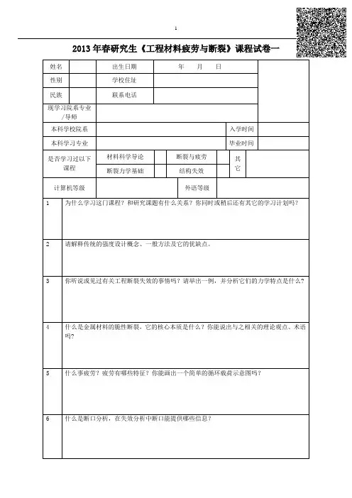
2013年春研究生《工程材料疲劳与断裂》课程试卷一姓名出生日期年月日性别学校住址民族联系电话现学习院系专业/导师本科学校院系入学时间本科学习专业毕业时间是否学习过以下课程材料科学导论断裂与疲劳其它断裂力学基础结构失效计算机等级外语等级1 为什么学习这门课程?和研究课题有什么关系?你同时或稍后还有其它的学习计划吗?2 请解释传统的强度设计概念、一般方法及它的优缺点。
3 你听说或见过有关工程断裂失效的事情吗?请举出一例,并分析它们的力学特点是什么?4 什么是金属材料的脆性断裂,它的核心本质是什么?你能说出与之相关的理论观点、术语吗?5 什么事疲劳?疲劳有哪些特征?你能画出一个简单的循环载荷示意图吗?6 什么是断口分析,在失效分析中断口能提供哪些信息?7 疲劳断口和静载破坏断口有什么不同?8 已知循环最大应力s max =200MPa,最小应力s min =50MPa,计算循环应力变程Δs,应力幅s a ,平均应力s m 和应力比R9 The S-N curve of a material is described by the relationship)/1(10log max σS N -=,where N is the number of cycles to failure, S is theamplitude of the applied cyclic stress, and max σis the monotonic fracture strength ,i.e.,S=max σ at N=1. A rotating component made of this material is subjected to 104 cycles at S=0.5max σ.If the cyclic load is now increased to S=0.75max σ, how many more cycles will the material withstand?10Translation E2CFatigue Crack NucleationFatigue cracks nucleate at singularities or discontinuities in most materials. Discontinuities may be on the surface or in the interior of the material. The singularities can be structural (such as inclusions or second-phase particles) or geometrical (such as scratches or steps). The explanation of preferential nucleation of fatigue cracks at surfaces perhaps resides in the fact that plastic deformation is easier there and that slip steps form on the surface. Slip steps alone can be responsible for initiating cracks, or they can interact with existing structural or geometric defects to produce cracks. Surface singularities may be present from the beginning or may develop during cyclic deformation, as, for example, the formation of intrusions and extrusions at what are called the persistent slip bands (PSBs) in metals. These bands were first observed in copper and nickel by Thompson et al .4 They appeared after cyclic deformation and persisted even after electropolishing. On retesting, slip bands appeared again in the same places. Later, the dislocation structure in the PSBs was investigated extensively. Figure 14.11(a) shows a TEM micrograph of a polycrystalline copper sample that was cycled to a total strain amplitude of 6.4 × 10⁻⁴ for 3 × 10⁵ cycles. Fatigue cycling was carried out in reverse bending at room temperature and at a frequency of 17 Hz. The thin foil was taken 73 μm below the surface. Two parallel PSBs (diagonally across the micrograph) embedded in a veined structure in polycrystalline copper can be seen. The PSBs are clearly distinguished and consist of a series of parallel ‘‘hedges” (a ladder). These ladders are channels through which the dislocations move and produce intrusions andextrusions at the surface Figure 14.11(c). Stacking-fault energy and the concomitant ease or difficulty of cross-slip play an important role in the development of the dislocation structure in the PSBs. Kuhlmann-Wilsdorf and Laird have discussed models for the formation of PSBs in metals.5 They compared the deformation substructures produced by unidirectional and cyclic (fatigue) deformation and interpreted them in terms of the differences between the two modes of deformation. The principal differences are as follows:1. Due to the much larger time spans of deformation in fatigue, the dislocation structures formed are much closer to the configurations having minimum energy than the ones generated by monotonic straining. That is, more stable dislocation arrays are observed after fatigue.2. The oft-repeated to-and-fro motion in fatigue minimizes the buildup of surpluses of local Burgers vectors, which are fairly prevalent after unidirectional (monotonic) strain.3. Much higher local dislocation densities are found in fatigued specimens.。
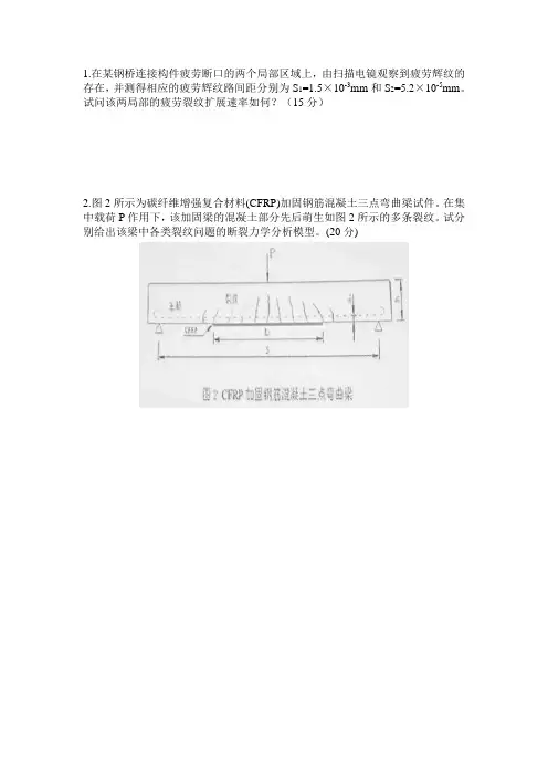
1.在某钢桥连接构件疲劳断口的两个局部区域上,由扫描电镜观察到疲劳辉纹的存在,并测得相应的疲劳辉纹路间距分别为S1=1.5×10⁻³mm和S2=5.2×10⁻⁵mm。
试问该两局部的疲劳裂纹扩展速率如何?(15分)
2.图2所示为碳纤维增强复合材料(CFRP)加固钢筋混凝土三点弯曲梁试件。
在集中载荷P作用下,该加固梁的混凝土部分先后萌生如图2所示的多条裂纹。
试分别给出该梁中各类裂纹问题的断裂力学分析模型。
(20分)
3.已知某导弹壳体是内径D=1500mm,壁厚t=5mm的圆筒形压力容器,沿轴向有一深a=2mm,长2c=8mm的表面裂纹。
(1) 打压时容器在65个大气压力下发生爆破。
材料的屈服强度σs=160Kg/mm2,试求该材料的K1C。
(10分)
(2)若da/dN=1.59×10-9(ΔK)2/3(K的单位为:Kg/mm3/2),并把容器的一次冲压卸载看作一个脉动循环,当内压力为30个大气压时,求容器的使用寿命。
(15分)
6.试比较混凝土与金属材料的断裂韧性测试方法的不同之处。
(15分)。

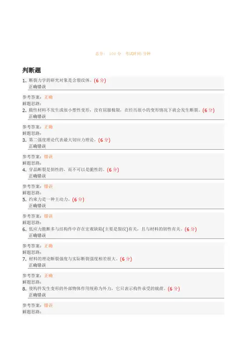
总分: 100分考试时间:分钟判断题1. 断裂力学的研究对象是含裂纹体。
(6分)正确错误参考答案:正确解题思路:2. 脆性材料不发生或很小塑性变形,没有屈服极限,在经历很小的变形情况下就会发生断裂。
(6分)正确错误参考答案:正确解题思路:3. 第二强度理论代表最大切应力理论。
(6分)正确错误参考答案:错误解题思路:4. 穿晶断裂是韧性的,而不可以是脆性的。
(6分)正确错误参考答案:错误解题思路:5. 约束力是一种主动力。
(6分)正确错误参考答案:错误解题思路:6. 低应力脆断多与结构件中存在宏观缺陷(主要是裂纹)有关,且与材料的韧性有关。
(6分)正确错误参考答案:正确解题思路:7. 材料的理论断裂强度与实际断裂强度相差很大。
(6分)正确错误参考答案:正确解题思路:8. 使构件发生变形的外部物体作用统称为外力,它只表示构件承受的载荷。
(6分)正确错误参考答案:错误解题思路:9. 根据材料断裂的载荷性质,断裂力学分为静态断裂力学和动态断裂力学,断裂动力学是断裂静力学的基础。
(6分)正确错误参考答案:错误解题思路:10. 材料的断裂是一个很复杂的过程,是材料性质、载荷类型、复役环境、构件尺寸等多种因素共同作用的结果,并且可能造成灾难性事故,因此断裂控制是无规律可循的。
(6分)正确错误参考答案:错误解题思路:填空题11. 载荷按性质分类有拉伸载荷、压缩载荷和___(1)___ 载荷。
(5分)(1).参考答案:剪切12. 由于作用循环载荷而性能变劣造成的断裂称为___(2)___ 。
(5分)(1).参考答案:疲劳断裂13. 材料(或构件)断裂前有明显的塑性变形,即断裂应变较大的断裂方式为___(3)___ 。
(5分) (1).参考答案:韧性断裂单选题14. 断裂化学则是研究各种对材料断裂过程的作用及影响的一门学科。
由此可见,断裂学是一门综合性的边缘学科,本书将以断裂力学为主,而为了更好理解断裂机理和裂纹扩展,断裂物理的知识也有所涉及。

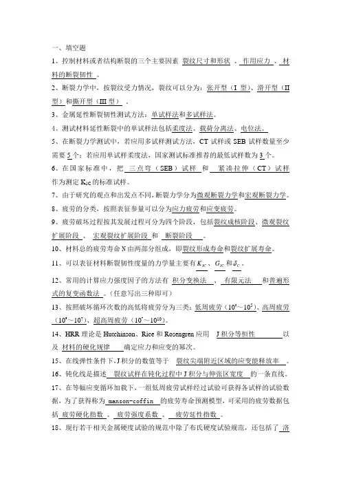
一、填空题1、控制材料或者结构断裂的三个主要因素 裂纹尺寸和形状 、 作用应力 、 材料的断裂韧性 。
2、断裂力学中,按裂纹受力情况,裂纹可以分为:张开型(I 型)、滑开型(II 型)和撕开型(III 型) 。
3、金属延性断裂韧性测试方法:单试样法和多试样法。
4、测试材料延性断裂中的单试样法包括柔度法、载荷分离法、电位法。
5、在断裂力学测试中,若应用多试样测试方法,CT 试样或SEB 试样数量至少需要5个;若应用单试样柔度法,国家测试标准推荐的最低试样数为3个。
6、在国家标准中,把 三点弯(SEB )试样 和 紧凑拉伸(CT )试样 作为测定K 1C 的标准试样。
7、由于研究的观点和出发点不同,断裂力学分为微观断裂力学和宏观断裂力学。
8、疲劳的分类,按照表征参量可以分为应力疲劳和应变疲劳。
9、疲劳破坏过程按其发展过程可分为四个阶段,包括裂纹成核阶段、微观裂纹扩展阶段 、 宏观裂纹扩展阶段 和 断裂阶段 。
10、材料总的疲劳寿命N 由两部分组成,即裂纹形成寿命和裂纹扩展寿命。
11、可以表征材料断裂韧性度量的力学量主要有IC K 、IC G 和C 。
12、常用的计算应力强度因子的方法有 积分变换法 、 有限元法 和普遍形式的复变函数法 。
(任意写出三种即可)13、按照破坏循环次数的高低将疲劳分为三类:低周疲劳(102~105)、高周疲劳(105~107)、超高周疲劳(107~1010)。
14、HRR 理论是Hutchinson 、Rice 和Rosengren 应用 J 积分等恒性 以及 材料的硬化规律 确定应力和应变的幂次。
15、在线弹性条件下,J 积分的数值等于 裂纹尖端附近区域的应变能释放率 。
16、钝化线是描述 裂纹试样在钝化过程中J 积分与伸张区宽度 的一条直线。
17、在等幅应变循环加载下,一组低周疲劳试样经过试验可获得各试样的试验数据,为了获得称为 manson-coffin 的疲劳寿命预测模型,可采用的疲劳数据包括 疲劳硬化指数 、 疲劳强度系数 、 疲劳延性指数 。
2013年春研究生《工程材料疲劳与断裂》课程试卷一姓名出生日期年月日
性别学校住址
民族联系电话
现学习院系专业
/导师
本科学校院系入学时间
本科学习专业毕业时间
是否学习过以下
课程材料科学导论断裂与疲劳其
它断裂力学基础结构失效
计算机等级外语等级
1 为什么学习这门课程?和研究课题有什么关系?你同时或稍后还有其它的学习计划吗?
2 请解释传统的强度设计概念、一般方法及它的优缺点。
3 你听说或见过有关工程断裂失效的事情吗?请举出一例,并分析它们的力学特点是什么?
4 什么是金属材料的脆性断裂,它的核心本质是什么?你能说出与之相关的理论观点、术语
吗?
5 什么事疲劳?疲劳有哪些特征?你能画出一个简单的循环载荷示意图吗?
6 什么是断口分析,在失效分析中断口能提供哪些信息?
7 疲劳断口和静载破坏断口有什么不同?
8 已知循环最大应力s max =200MPa,最小应力s min =50MPa,计算循环应力变程Δs,应力幅s a ,平均应力s m 和应力比R
9 The S-N curve of a material is described by the relationship
)/1(10log max σS N -=,where N is the number of cycles to failure, S is the
amplitude of the applied cyclic stress, and max σis the monotonic fracture strength ,i.e.,S=max σ at N=1. A rotating component made of this material is subjected to 104 cycles at S=0.5max σ.If the cyclic load is now increased to S=0.75max σ, how many more cycles will the material withstand?
10
Translation E2C
Fatigue Crack Nucleation
Fatigue cracks nucleate at singularities or discontinuities in most materials. Discontinuities may be on the surface or in the interior of the material. The singularities can be structural (such as inclusions or second-phase particles) or geometrical (such as scratches or steps). The explanation of preferential nucleation of fatigue cracks at surfaces perhaps resides in the fact that plastic deformation is easier there and that slip steps form on the surface. Slip steps alone can be responsible for initiating cracks, or they can interact with existing structural or geometric defects to produce cracks. Surface singularities may be present from the beginning or may develop during cyclic deformation, as, for example, the formation of intrusions and extrusions at what are called the persistent slip bands (PSBs) in metals. These bands were first observed in copper and nickel by Thompson et al .4 They appeared after cyclic deformation and persisted even after electropolishing. On retesting, slip bands appeared again in the same places. Later, the dislocation structure in the PSBs was investigated extensively. Figure 14.11(a) shows a TEM micrograph of a polycrystalline copper sample that was cycled to a total strain amplitude of 6.4 × 10⁻⁴ for 3 × 10⁵ cycles. Fatigue cycling was carried out in reverse bending at room temperature and at a frequency of 17 Hz. The thin foil was taken 73 μm below the surface. Two parallel PSBs (diagonally across the micrograph) embedded in a veined structure in polycrystalline copper can be seen. The PSBs are clearly distinguished and consist of a series of parallel ‘‘hedges” (a ladder). These ladders are channels through which the dislocations move and produce intrusions and
extrusions at the surface Figure 14.11(c). Stacking-fault energy and the concomitant ease or difficulty of cross-slip play an important role in the development of the dislocation structure in the PSBs. Kuhlmann-Wilsdorf and Laird have discussed models for the formation of PSBs in metals.5 They compared the deformation substructures produced by unidirectional and cyclic (fatigue) deformation and interpreted them in terms of the differences between the two modes of deformation. The principal differences are as follows:
1. Due to the much larger time spans of deformation in fatigue, the dislocation structures formed are much closer to the configurations having minimum energy than the ones generated by monotonic straining. That is, more stable dislocation arrays are observed after fatigue.
2. The oft-repeated to-and-fro motion in fatigue minimizes the buildup of surpluses of local Burgers vectors, which are fairly prevalent after unidirectional (monotonic) strain.
3. Much higher local dislocation densities are found in fatigued specimens.。