Fresnelets—A new wavelet basis for digital holography
- 格式:pdf
- 大小:358.56 KB
- 文档页数:6
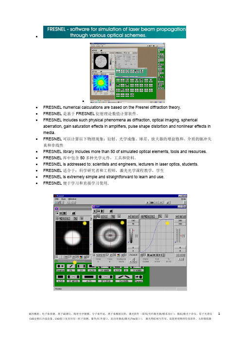
∙∙∙FRESNEL numerical calculations are based on the Fresnel diffraction theory.∙FRESNEL是基于FRESNEL衍射理论数值计算软件。
∙FRESNEL includes such physical phenomena as diffraction, optical imaging, spherical aberration, gain saturation effects in amplifiers, pulse shape distortion and nonlinear effects in media.∙FRESNEL可以计算以下物理现象:衍射、光学成像、球差、放大器的增益饱和、介质的脉冲失真和非线性∙FRESNEL library includes more than 50 of simulated optical elements, tools and resources.∙FRESNEL库中包含50多种光学元件,工具和资料。
∙FRESNEL is addressed to: scientists and engineers, lecturers in laser optics, students.∙FRESNEL适合于:科学研究者和工程师,激光光学课程教学,学生∙FRESNEL is extremely simple and straightforward to learn and use.∙FRESNEL便于学习和直接学习使用.The latest FRESNEL 4.0 is now capable to simulate nonlinear optics effects, such as self-focusing, second and third harmonic generation, and multipass schemes. All FRESNEL versions feature optimized modeling procedures, variety of input beams, optical elements and special resources, comfortable interface, extensive support options.最新的FRESNEL 4.0可以模拟非线性光学效应,例如,自聚焦、二次和三次谐波、和多通道方案。
/cgi/content/full/341/6146/640/DC1Supplementary Materials forA Semi-Floating Gate Transistor for Low-Voltage Ultrafast Memoryand Sensing OperationPeng-Fei Wang,* Xi Lin, Lei Liu, Qing-Qing Sun, Peng Zhou, Xiao-Yong Liu, Wei Liu, YiGong, David Wei Zhang*Corresponding author. E-mail: pfw@Published 9 August 2013, Science341, 640 (2013)DOI: 10.1126/science.1240961This PDF file includes:Materials and MethodsSupplementary TextFigs. S1 to S8ReferenceMaterials and MethodsThe Semi-Floating-Gate (SFG) transistors were fabricated using the 0.18-μm manufacturing technologies with specifically designed ion-implant processes and photolithography masks. The process flow and device structures are summarized in Fig. S1. First, a phosphorous-doped drain extension region was formed by ion-implantation and a 6-nm gate oxide layer was grown (Fig. S1A). Then a contact window inside the gate oxide was opened by lithography and buffered-HF wet etching. Boron was implanted into this contact window using the photo-resist as a masking layer (Fig. S1B). After that, the first boron-doped poly-Si layer was deposited and contacted the drain extension region via the aforementioned contact window. The Semi-FG pattern was then formed by lithography and reactive ion etching process which stops on the underlying thin SiO2 layer. This plasma-damaged SiO2 layer was then etched away and a 6 nm SiO2 dielectric was grown and nitrided as the inter-poly-dielectric. An n+-doped poly-Si was then deposited and the control-gate structure shown in Fig. S1C was formed. After the spacer processes, arsenic ions were implanted to form the heavily n-doped source and drain regions. The transmission electron microscope (TEM) cross-sections of the device are shown in Fig. S1D. In Fig. S1E, there is a SiO2 layer between the p+ doped poly-Si and the silicon substrate. However, at the position indicated in Fig. S1F, that SiO2 layer was etched away. With the p+ poly contacts the n-doped drain extension region, a floating pn-junction is formed and became the floating-gate of the device. The processed structures show very good process compatibility with the commercial dual-poly-gate manufacturing technology. Only minor modifications on the standard manufacturing process flow are required and high device yield on 8-inch silicon wafer is obtained. To further reduce the cell size, self-aligned techniques can be used to minimize the size of contact window between the p+ poly and the n-extension region.Supplementary TextThe DC characteristics of the SFG transistors were measured using a parameter analyzer (model Agilent B1500) and a RF probe-station. Figs. S2A to S2D compare the device symbols, the typical transfer I-V curves for MOSFET, FG-MOSFET, and two types of SFG transistors. For comparison, a MOSFET has a gate over the semiconductor channel (Fig. S2A) and a floating-gate MOSFET has a floating-gate between the control-gate and the semiconductor channel (Fig. S2B). The floating-gate MOSFET stores logic “0” with high V th or “1” with low V th by changing the amount of charge inside the floating-gate. By adding a diode or a gated diode between the floating-gate and the drain electrode of FG-MOSFET, a SFG transistor is realized. When the SFG transistor is exposed under light, the photo-carriers generated from the pn-junction diode will be partially collected by the floating-gate and in turn the I D-V CG curves will shift accordingly when changing the light intensity and exposure time. The change in threshold voltage of SFG transistor ( ) is expressed as , where is the change of the amount of charges inside the floating-gate (), is the floating-gate capacitance, and is the coupling ratio of control-gate (S1). During the light exposure process, is increased due to the photocurrent flowing into the floating-gate. The device symbol andthe measured transfer I D-V CG curves for SFG transistor for light sensing are shown in Fig. S2C. It can be seen that V th decreases when the light intensity increases. The device symbol and the measured I D-V CG curves of a SFG transistor optimized for memory function are shown in Fig. S2D. Compared to the SFG transistor shown in Fig. S2C, this SFG cell extends the control-gate over the pn-diode. A gate controlled diode or Tunneling FET (TFET) is formed and connects the semi-floating-gate to the drain. As a result, the TFET can now be used to charge or discharge the floating-gate. The current of TFET depends on the band-to-band tunneling generation rate, i.e. . G BTBT is the band-to-band tunneling generation rate, and it is expressed as. A BTBT and B BTBT are constants, E g is the band-gap energy, and E is the magnitude of the electric field. With a higher V D, the electric field increases and the charge current increases exponentially. As shown in Fig. S2D, the threshold voltage decreases when the drain voltage increases. Fast switching behavior is also observed in the transfer I D-V CG curves. The subthreshold swing even reaches 30 mV/dec when V D equals 3.0V.Because SFG transistor has an entirely new device structure, process and device simulations were carried out using Silvaco TCAD tools before device fabrication. First, the process simulations were performed. The resulted structure was then imported to the device simulator for transient behavior simulation. The ion-implantation conditions were designed for the optimized device performance from the device simulation. Asymmetric doping profiles for the source and drain of the embedded P-TFET are specifically designed to obtain the favorable device electrical behavior. Since the processing parameters were obtained from the process simulation results, the simulated structure is almost identical to the experimental device structure shown in Fig. S1D. The models for simulating a conventional MOSFET were included in the SFG transistor simulation. In addition, Kane’s local band-to-band tunneling model was included for simulating the tunneling current during the device operation. Fig. S3A - S3D display the simulated device structures with current and potential contours. The writing-1 operation is with V CG = -2.0 V and V D = 2.0 V. During the writing-1 operation, the drain is positively biased and the semi-floating-gate has a negative potential, resulting in current flows from the drain to the semi-floating-gate (Fig. S3A). The writing-0 operation is with V CG = 2.0 V and V D = 0 V. During the writing-0 operation, the n+ drain is biased with 0 V and the semi-floating-gate potential is elevated by the capacitive coupling of increased V CG, resulting in current flows from the semi-floating-gate to the drain (Fig. S3B). After writing-1 and writing-0 operations, the potential contours for the “1” and “0” devices at the standby status are plotted in Fig. S3C and S3D. It can be seen that the semi-floating-gate potential of the “1” state is 0.75 V, which is 1.64 V higher than that of the “0” state with the same bias conditions.The transient electrical behavior of the simulated device is shown in Fig. S3E. With the band-to-band tunneling model turned on, the high-speed memory function is realized (black line in the read-out current subfigure of Fig. S3E). It is found from the simulation that the gate-controlled band-to-band tunneling current is the key to high speed writingoperation, especially at the nano-second level. The green line in the read-out current subfigure of Fig. S3E is simulated with the band-to-band tunneling model turned off. It can be seen that writing-1 operation does not work with the same voltage setting. For comparison, the measured transient operation characteristic of the SFG transistor is shown in Fig. S3F. The transient behavior of the measured device is similar to the simulated device with band-to-band tunneling model.The transient behaviors of SFG transistors were measured using the circuit configuration shown in Fig. S4A. The measurement environment includes a RF probe-station, a pulse generator, a transimpedance amplifier circuit, and a high-speed oscilloscope. Two channel signal pulses were generated by the pulse generator (Agilent 81160A) and coupled to the drain and the control-gate electrodes of SFG transistor. A transimpedance amplifier circuit (Fig. S4B) was designed to convert the read-out current of SFG transistor to voltage signal for oscilloscope tracing. In Fig. S4C, the examples of traces captured by the oscilloscope during transient operation are shown. The writing-1 operation was performed by pulses of V D = 2V and V CG = -2V for 3 ns. Then, during the read operation, the voltage drop on the feedback resistor R f was measured by the oscilloscope and then converted to the I drain signal shown in Fig. S4D. It can be seen the readout current is about 2 μA after a 3-ns writing “1” operation. Unlike the conventional DRAM cell, the read operation of the SFG memory device is non-destructive because of its gain cell nature, which means no write-back operation is needed after the reading operation.In order to evaluate the operation speed of SFG transistor for memory application, short writing time with the target pulse width of 0.6 ns was executed (Fig. S5A). Due to the parasitic capacitance of the measurement cables, the rising / falling edges were 0.9 ns and the actual peak width at half height (PWHH) was increased to 1.3 ns. However, the writing-1 and writing-0 operations were successfully demonstrated in Fig. S5B. Meanwhile, it was found that the off-chip read-out circuit oscillates at the beginning of reading operation. Figs. S5B to S5D show the transient operation of the devices with different reading operation time. The reading operation duration was 9 μs in Fig. S5B. First, a writing-1 operation was performed with V D= 2V and V CG= -1.8V. A read-out current of about 1.5 μA was measured for the “1” cell. Then, a writing-0 operation was performed with V D= 0V and V CG= 2V. A very small current representing “0” was measured for the “0” cell. It can be seen that the read-out current oscillates at the beginning of the reading operation. With longer reading time such as 22.4 μs and 45 μs shown in Figs. S5C and S5D, the read-out current became stable. The oscillation was caused by the amplification circuit board (Fig. S4B) which can be improved by using the on-chip read-out circuits. Meanwhile, higher operation speed is expected by reducing the rising / falling edges of the pulses when using the integrated supporting circuits.In Figure S6A, 40 test devices were tested. The operation sequence was writing-0, reading, writing-1, and then reading. A “0” could be written into the transistor with V D of -1V and V CG of 2 V for 3 ms. During the subsequent reading operation, a very small drain current of 30 nA was measured with V D = 2 V and V CG = 2 V. After a writing-1 operation at V D =2 V and V CG = -2 V for 3 ms, the threshold voltage was lowered and a large draincur rent of about 2 μA was measured with V D = 2 V and V CG = 2 V. The wafer map of the reading-1 drain current of 40 test devices showed high uniformity across the whole wafer. The retention time and operation endurance properties were evaluated. In Fig. S6B, the retention time for “0” cell reaches 1 second at room temperature, while the “1” cell does not have retention issue because the semi-floating-gate voltage will be pinned to the drain voltage in the standby state. The retention performance of “0” is good because of the low leakage current of reversely biased p-n structure in the standby status. In Fig. S6C, the device operation endurance was investigated by repeating the full operation sequences. Almost no degradation was observed for 1012cycles of operation. The extrapolated endurance reaches 1015, which is far beyond the endurance of 106 for the conventional floating-gate memory cell.As a memory device, the immunity to various disturb mechanisms is also very important. Figs. S7A to S7F show the disturb properties of SFG memory cell measured at room temperature. Six types of disturb mechanisms on “1” and “0” cells are characterized. Most of the disturb endurances exceed 100 ms except for the disturbance of the writing-0 control-gate voltage on the “1” cell when V D at standby status is set to 1.0 V. During this writing-0 V CG disturb with V CG = 2.0 V and V D = 1.0 V, the pn junction will be weakly forward-biased if “1” is already stored inside the cell. The disturb endurances can be further improved by optimizing the operation voltages and the operation sequences. Using the image sensing SFG transistor, an imaging array can be configured. In Fig. S8, the schematic view of the SFG image sensor array is shown. The source lines and bit lines are arranged above the shallow trench isolation (STI) structure to maximize the fill factor. Using SFG cell as an APS cell, the pixel density of image sensing chip can be increased and the reading operation becomes non-destructive.Fig. S1.Brief summary of the process flow for fabricating the SFG transistor (A to C) and the TEM pictures of SFG transistor along the channel direction (D to F). Inset E is taken from the MOSFET channel where poly-Si on SiO2 can be seen. Inset F is taken from the contact interface between semi-floating-gate and n-doped drain extension region whereno oxide interface exists.Fig. S2Device symbols and transfer characteristics for MOSFET (A), FG-MOSFET (B), and SFG transistors (C, D). The semi-floating-gate is realized by connecting the floating-gate of FG-MOSFET to the drain via a pn junction diode. When the diode works as a photo-diode, photo-sensing function can be realized. When extending the control-gate over the diode, an embedded TFET is formed and dramatically accelerates the writing-1operation.Fig. S3(A, B) Simulated current contours of writing-1 operation and writing-0 operation. During the writing-1 operation, the drain is positively biased and the semi-floating-gate has a negative potential. Current will flow from the drain to the semi-floating-gate. During the writing-0 operation, the n+ drain is biased with 0 V and the semi-floating-gate potential is elevated by the capacitive coupling of increased V CG. Current will flow from the semi-floating-gate to the drain. (C, D) Simulated potential contours for the “1” and “0” devices at the standby state. The semi-floating-gate potential of the “1” state is higher than that of the “0” state with the same external voltages. (E) Simulated transient operation of the SFG transistor. V CG, V D, and the read out I D are displayed separately. In the read out I D figure the simulation results with or without the band-to-band tunneling model are compared. Device does not work when the band-to-band tunneling model is turned off in the simulation. (F) Experimental transient operations are shown for comparison with thesimulation results of Fig. S3E.Fig. S4(A) Transient measurement circuit. The measurement environment includes a RF probe-station, a pulse generator, a transimpedance amplifier circuit, and a high-speed oscilloscope. (B) Specific transimpedance amplifier circuit for converting the current signal to voltage signal for oscilloscope tracing. (C) Examples of measured voltage signals shown on the screen of oscilloscope. (D) Control-gate voltage, drain voltage, and the read-out current of a SFG transistor using 3-ns writing-1 pulse. The voltages are measured directly and the read-out current is converted from the voltage-drop on thefeedback resistor.Fig. S5(A) Measured drain voltage and control-gate voltage pulses for writing “1” and writing “0”, where the peak-width-at-half-height (PWHH) is measured as 1.3 ns. Transient measurement sequence of writing “1” - standby - reading - writing “0” - standby -reading with various reading pulse widths of 9 μs (B), 22.5 μs (C), and 45μs (D).Fig. S6(A) Measured reading-1 drain current wafer map and two transient operation cycles of 40 SFG transistors. The operation sequence is writing-0, reading, writing-1, and then reading. (B) Data retention time of “1” and “0” at room temperature. The read-out operation is performed with various standby periods after the writing operation. (C) Measured operation endurance property. Full writing-reading sequences are repeated with3 ns writing time.Fig. S7Disturb performances of SFG memory cell measured at room temperature. (A) Writing-1 V D disturb on the “1” and “0” cells. (B) Writing-1 V CG disturb on the “1” and “0” cells.(C) Writing-0 V D disturb on the “1” and “0” cells. (D) Writing-0 V CG disturb on the “1” and “0” cells. (E) Reading-operation V D disturb on the “1” and “0” cells. (F) Reading-operation V CG disturb on the “1” and “0” cells.Fig. S8Schematic view of the SFG image sensor array. The source lines and bit lines arearranged above the shallow trench isolation (STI) structure to maximize the fill factor.ReferencesS1. P. Pavan, L. Larcher, and A. Marmiroli, Floating gate devices: operation and compact modeling (Kluwer Acdemic Publisher, Dordrecht, 2004), pp. 37-40.。


Eliminate Signal Noise With Discrete Wavelet TransformationThe wavelet transform is a mathematical tool that's becoming quite useful for analyzing many types of signals. It has been proven especially useful in data compression, as well as in adaptive equalizer and transmultiplexer applications.信号噪声消除和离散小波变换小波变换是一种在分析成为许多类型的信号很有用的数学工具。
它已被证明在数据压缩以及自适应均衡器和transmultiplexer应用中有特别的用途。
A wavelet is a small, localized wave of a particular shape and finite duration. Several families, or collections of similar types of wavelets, are in use today. A few go by the names of Haar, Daubechies, and Biorthogonal. Wavelets within each of these families share common properties. For instance, the Biorthogonal wavelet family exhibits linear phase, which is an important characteristic for signal and image reconstruction.小波是一种具有特定的形状与有限的时间的波。

第6章光源和放大器在光纤系统,光纤光源产生的光束携带的信息。
激光二极管和发光二极管是两种最常见的来源。
他们的微小尺寸与小直径的光纤兼容,其坚固的结构和低功耗要求与现代的固态电子兼容。
在以下几个GHz的工作系统,大部分(或数Gb /秒),信息贴到光束通过调节输入电流源。
外部调制(在第4、10章讨论)被认为是当这些率超标。
我们二极管LED和激光研究,包括操作方法,转移特性和调制。
我们计划以获得其他好的或理念的差异的两个来源,什么情况下调用。
当纤维损失导致信号功率低于要求的水平,光放大器都需要增强信号到有效的水平。
通过他们的使用,光纤链路可以延长。
因为光源和光放大器,如此多的共同点,他们都是在这一章处理。
1.发光二极管一个发光二极管[1,2]是一个PN结的半导体发光时正向偏置。
图6.1显示的连接器件、电路符号,能量块和二极管关联。
能带理论提供了对一个)简单的解释半导体发射器(和探测器)。
允许能带通过的是工作组,其显示的宽度能在图中,相隔一禁止区域(带隙)。
在上层能带称为导带,电子不一定要到移动单个原子都是免费的。
洞中有一个正电荷。
它们存在于原子电子的地点已经从一个中立带走,留下的电荷原子与净正。
自由电子与空穴重新结合可以,返回的中性原子状态。
能量被释放时,发生这种情况。
一个n -型半导体拥有自由电子数,如图图英寸6.1。
p型半导体有孔数自由。
当一种P型和一种N型材料费米能级(WF)的P和N的材料一致,并外加电压上作用时,产生的能垒如显示的数字所示。
重参杂材料,这种情况提供许多电子传到和过程中需要排放的孔。
在图中,电子能量增加垂直向上,能增加洞垂直向下。
因此,在N地区的自由电子没有足够的能量去穿越阻碍而移动到P区。
同样,空穴缺乏足够的能量克服障碍而移动进入n区。
当没有外加电压时,由于两种材料不同的费米能级产生的的能量阻碍,就不能自由移动。
外加电压通过升高的N端势能,降低一侧的P端势能,从而是阻碍减小。
如果供电电压(电子伏特)与能级(工作组)相同,自由电子和自由空穴就有足够的能量移动到交界区,如底部的数字显示,当一个自由电子在交界区遇到了一个空穴,电子可以下降到价带,并与空穴重组。
光频率介质纤维表面波导Dielectric-fibre surface waveguides for optical frequencies高锟(G.A. Hockham)关键词:光学纤维,波导摘要:折射率高于周围区域的介质纤维是作为在光频段引导传输的可能的介质的一种介电波导形式。
文章中讨论的这种特殊的结构形式是圆的横截面。
用作通信目的的光波导传播模式的选择通常主要考虑损耗特性和信息容量。
文章中讨论了介电损耗,弯曲损耗和辐射损耗并且讨论了与信息容量相关的模式稳定,色散和功率控制,同时也讨论了物理实现方面,也包含 了对对光学和微波波长的实验研究。
主要符号列表:n J = n 阶的第一类贝塞尔函数n K = 2π修正的第二类n 阶的变型贝塞尔函数β = g2λπ,波导的相位系数 n J ' = n J 的一阶导数n K ' = n K 的一阶导数i h = 衰减系数或辐射波数i ε = 相对介电常数0k = 自由空间传播系数a = 光纤半径γ = 纵向传播系数k = 波耳兹曼常数T = 绝对温度,Kc β = 等温可压缩性λ = 波长n = 折射率)(H i υ = 第υ阶Hankel 函数的第i 阶导数υH ' = υH 的导数 υ = 方位角传播系数=21υυj -L = 调制周期下标n 是整数,下标m 是n J = 0的第m 个根。
1. 简介折射率高于周围区域的介质纤维是一种介电波导,它代表了光频段中能量有向传输的一种媒介。
这种结构形式引导电磁波沿着不同折射率区域的特定边界传播,相关电磁场部分在光纤内部分在光纤外。
外部电磁场在垂直于传播方向上是逐渐消失的,以且在无穷远处以近似指数的形式衰减到零。
这种结构经常被称为开放波导,以表面波模式传播。
下面要讨论的是具有圆形截面的特种介质纤维波导。
2.介质纤维波导具有圆形截面的介质纤维能够传输所有的H 0m 模、E 0m 模和HE nm 混合模。
a r X i v :g r -q c /0411082v 1 16 N o v 2004Laser Ranging to the Moon,Mars and BeyondSlava G.Turyshev,James G.Williams,Michael Shao,John D.AndersonJet Propulsion Laboratory,California Institute of Technology,4800Oak Grove Drive,Pasadena,CA 91109,USAKenneth L.Nordtvedt,Jr.Northwest Analysis,118Sourdough Ridge Road,Bozeman,MT 59715USA Thomas W.Murphy,Jr.Physics Department,University of California,San Diego 9500Gilman Dr.,La Jolla,CA 92093USA Abstract Current and future optical technologies will aid exploration of the Moon and Mars while advancing fundamental physics research in the solar system.Technologies and possible improvements in the laser-enabled tests of various physical phenomena are considered along with a space architecture that could be the cornerstone for robotic and human exploration of the solar system.In particular,accurate ranging to the Moon and Mars would not only lead to construction of a new space communication infrastructure enabling an improved navigational accuracy,but will also provide a significant improvement in several tests of gravitational theory:the equivalence principle,geodetic precession,PPN parameters βand γ,and possible variation of the gravitational constant G .Other tests would become possible with an optical architecture that would allow proceeding from meter to centimeter to millimeter range accuracies on interplanetary distances.This paper discusses the current state and the future improvements in the tests of relativistic gravity with Lunar Laser Ranging (LLR).We also consider precision gravitational tests with the future laser rangingto Mars and discuss optical design of the proposed Laser Astrometric Test of Relativity (LATOR)mission.We emphasize that already existing capabilities can offer significant improvements not only in the tests of fundamental physics,but may also establish the infrastructure for space exploration in the near future.Looking to future exploration,what characteristics are desired for the next generation of ranging devices,what is the optimal architecture that would benefit both space exploration and fundamental physics,and what fundamental questions can be investigated?We try to answer these questions.1IntroductionThe recent progress in fundamental physics research was enabled by significant advancements in many technological areas with one of the examples being the continuing development of the NASA Deep Space Network –critical infrastructure for precision navigation and communication in space.A demonstration of such a progress is the recent Cassini solar conjunction experiment[8,6]that was possible only because of the use of Ka-band(∼33.4GHz)spacecraft radio-tracking capabilities.The experiment was part of the ancillary science program–a by-product of this new radio-tracking technology.Becasue of a much higher data rate transmission and, thus,larger data volume delivered from large distances the higher communication frequency was a very important mission capability.The higher frequencies are also less affected by the dispersion in the solar plasma,thus allowing a more extensive coverage,when depp space navigation is concerned.There is still a possibility of moving to even higher radio-frequencies, say to∼60GHz,however,this would put us closer to the limit that the Earth’s atmosphere imposes on signal transmission.Beyond these frequencies radio communication with distant spacecraft will be inefficient.The next step is switching to optical communication.Lasers—with their spatial coherence,narrow spectral emission,high power,and well-defined spatial modes—are highly useful for many space applications.While in free-space,optical laser communication(lasercomm)would have an advantage as opposed to the conventional radio-communication sercomm would provide not only significantly higher data rates(on the order of a few Gbps),it would also allow a more precise navigation and attitude control.The latter is of great importance for manned missions in accord the“Moon,Mars and Beyond”Space Exploration Initiative.In fact,precision navigation,attitude control,landing,resource location, 3-dimensional imaging,surface scanning,formationflying and many other areas are thought only in terms of laser-enabled technologies.Here we investigate how a near-future free-space optical communication architecture might benefit progress in gravitational and fundamental physics experiments performed in the solar system.This paper focuses on current and future optical technologies and methods that will advance fundamental physics research in the context of solar system exploration.There are many activities that focused on the design on an optical transceiver system which will work at the distance comparable to that between the Earth and Mars,and test it on the Moon.This paper summarizes required capabilities for such a system.In particular,we discuss how accurate laser ranging to the neighboring celestial bodies,the Moon and Mars,would not only lead to construction of a new space communication infrastructure with much improved navigational accuracy,it will also provide a significant improvement in several tests of gravitational theory. Looking to future exploration,we address the characteristics that are desired for the next generation of ranging devices;we will focus on optimal architecture that would benefit both space exploration and fundamental physics,and discuss the questions of critical importance that can be investigated.This paper is organized as follows:Section2discusses the current state and future per-formance expected with the LLR technology.Section3addresses the possibility of improving tests of gravitational theories with laser ranging to Mars.Section4addresses the next logical step—interplanetary laser ranging.We discuss the mission proposal for the Laser Astrometric Test of Relativity(LATOR).We present a design for its optical receiver system.Section5 addresses a proposal for new multi-purpose space architecture based on optical communica-tion.We present a preliminary design and discuss implications of this new proposal for tests of fundamental physics.We close with a summary and recommendations.2LLR Contribution to Fundamental PhysicsDuring more than35years of its existence lunar laser ranging has become a critical technique available for precision tests of gravitational theory.The20th century progress in three seem-ingly unrelated areas of human exploration–quantum optics,astronomy,and human spaceexploration,led to the construction of this unique interplanetary instrument to conduct very precise tests of fundamental physics.In this section we will discuss the current state in LLR tests of relativistic gravity and explore what could be possible in the near future.2.1Motivation for Precision Tests of GravityThe nature of gravity is fundamental to our understanding of the structure and evolution of the universe.This importance motivates various precision tests of gravity both in laboratories and in space.Most of the experimental underpinning for theoretical gravitation has come from experiments conducted in the solar system.Einstein’s general theory of relativity(GR)began its empirical success in1915by explaining the anomalous perihelion precession of Mercury’s orbit,using no adjustable theoretical parameters.Eddington’s observations of the gravitational deflection of light during a solar eclipse in1919confirmed the doubling of the deflection angles predicted by GR as compared to Newtonian and Equivalence Principle(EP)arguments.Follow-ing these beginnings,the general theory of relativity has been verified at ever-higher accuracy. Thus,microwave ranging to the Viking landers on Mars yielded an accuracy of∼0.2%from the gravitational time-delay tests of GR[48,44,49,50].Recent spacecraft and planetary mi-crowave radar observations reached an accuracy of∼0.15%[4,5].The astrometric observations of the deflection of quasar positions with respect to the Sun performed with Very-Long Base-line Interferometry(VLBI)improved the accuracy of the tests of gravity to∼0.045%[45,51]. Lunar Laser Ranging(LLR),the continuing legacy of the Apollo program,has provided ver-ification of GR improving an accuracy to∼0.011%via precision measurements of the lunar orbit[62,63,30,31,32,35,24,36,4,68].The recent time-delay experiments with the Cassini spacecraft at a solar conjunction have tested gravity to a remarkable accuracy of0.0023%[8] in measuring deflection of microwaves by solar gravity.Thus,almost ninety years after general relativity was born,Einstein’s theory has survived every test.This rare longevity and the absence of any adjustable parameters,does not mean that this theory is absolutely correct,but it serves to motivate more sensitive tests searching for its expected violation.The solar conjunction experiments with the Cassini spacecraft have dramatically improved the accuracy in the solar system tests of GR[8].The reported accuracy of2.3×10−5in measuring the Eddington parameterγ,opens a new realm for gravitational tests,especially those motivated by the on-going progress in scalar-tensor theories of gravity.1 In particular,scalar-tensor extensions of gravity that are consistent with present cosmological models[15,16,17,18,19,20,39]predict deviations of this parameter from its GR value of unity at levels of10−5to10−7.Furthermore,the continuing inability to unify gravity with the other forces indicates that GR should be violated at some level.The Cassini result together with these theoretical predictions motivate new searches for possible GR violations;they also provide a robust theoretical paradigm and constructive guidance for experiments that would push beyond the present experimental accuracy for parameterized post-Newtonian(PPN)parameters(for details on the PPN formalism see[60]).Thus,in addition to experiments that probe the GR prediction for the curvature of the gravityfield(given by parameterγ),any experiment pushingthe accuracy in measuring the degree of non-linearity of gravity superposition(given by anotherEddington parameterβ)will also be of great interest.This is a powerful motive for tests ofgravitational physics phenomena at improved accuracies.Analyses of laser ranges to the Moon have provided increasingly stringent limits on anyviolation of the Equivalence Principle(EP);they also enabled very accurate measurements fora number of relativistic gravity parameters.2.2LLR History and Scientific BackgroundLLR has a distinguished history[24,9]dating back to the placement of a retroreflector array onthe lunar surface by the Apollo11astronauts.Additional reflectors were left by the Apollo14and Apollo15astronauts,and two French-built reflector arrays were placed on the Moon by theSoviet Luna17and Luna21missions.Figure1shows the weighted RMS residual for each year.Early accuracies using the McDonald Observatory’s2.7m telescope hovered around25cm. Equipment improvements decreased the ranging uncertainty to∼15cm later in the1970s.In1985the2.7m ranging system was replaced with the McDonald Laser Ranging System(MLRS).In the1980s ranges were also received from Haleakala Observatory on the island of Maui in theHawaiian chain and the Observatoire de la Cote d’Azur(OCA)in France.Haleakala ceasedoperations in1990.A sequence of technical improvements decreased the range uncertainty tothe current∼2cm.The2.7m telescope had a greater light gathering capability than thenewer smaller aperture systems,but the newer systemsfired more frequently and had a muchimproved range accuracy.The new systems do not distinguish returning photons against thebright background near full Moon,which the2.7m telescope could do,though there are somemodern eclipse observations.The lasers currently used in the ranging operate at10Hz,with a pulse width of about200 psec;each pulse contains∼1018photons.Under favorable observing conditions a single reflectedphoton is detected once every few seconds.For data processing,the ranges represented by thereturned photons are statistically combined into normal points,each normal point comprisingup to∼100photons.There are15553normal points are collected until March2004.Themeasured round-trip travel times∆t are two way,but in this paper equivalent ranges in lengthunits are c∆t/2.The conversion between time and length(for distance,residuals,and dataaccuracy)uses1nsec=15cm.The ranges of the early1970s had accuracies of approximately25cm.By1976the accuracies of the ranges had improved to about15cm.Accuracies improvedfurther in the mid-1980s;by1987they were4cm,and the present accuracies are∼2cm.One immediate result of lunar ranging was the great improvement in the accuracy of the lunarephemeris[62]and lunar science[67].LLR measures the range from an observatory on the Earth to a retroreflector on the Moon. For the Earth and Moon orbiting the Sun,the scale of relativistic effects is set by the ratio(GM/rc2)≃v2/c2∼10−8.The center-to-center distance of the Moon from the Earth,with mean value385,000km,is variable due to such things as eccentricity,the attraction of the Sun,planets,and the Earth’s bulge,and relativistic corrections.In addition to the lunar orbit,therange from an observatory on the Earth to a retroreflector on the Moon depends on the positionin space of the ranging observatory and the targeted lunar retroreflector.Thus,orientation ofthe rotation axes and the rotation angles of both bodies are important with tidal distortions,plate motion,and relativistic transformations also coming into play.To extract the gravitationalphysics information of interest it is necessary to accurately model a variety of effects[68].For a general review of LLR see[24].A comprehensive paper on tests of gravitationalphysics is[62].A recent test of the EP is in[4]and other GR tests are in[64].An overviewFigure1:Historical accuracy of LLR data from1970to2004.of the LLR gravitational physics tests is given by Nordtvedt[37].Reviews of various tests of relativity,including the contribution by LLR,are given in[58,60].Our recent paper describes the model improvements needed to achieve mm-level accuracy for LLR[66].The most recent LLR results are given in[68].2.3Tests of Relativistic Gravity with LLRLLR offers very accurate laser ranging(weighted rms currently∼2cm or∼5×10⁻¹¹in frac-tional accuracy)to retroreflectors on the Moon.Analysis of these very precise data contributes to many areas of fundamental and gravitational physics.Thus,these high-precision studies of the Earth-Moon-Sun system provide the most sensitive tests of several key properties of weak-field gravity,including Einstein’s Strong Equivalence Principle(SEP)on which general relativity rests(in fact,LLR is the only current test of the SEP).LLR data yielded the strongest limits to date on variability of the gravitational constant(the way gravity is affected by the expansion of the universe),and the best measurement of the de Sitter precession rate.In this Section we discuss these tests in more details.2.3.1Tests of the Equivalence PrincipleThe Equivalence Principle,the exact correspondence of gravitational and inertial masses,is a central assumption of general relativity and a unique feature of gravitation.EP tests can therefore be viewed in two contexts:tests of the foundations of general relativity,or as searches for new physics.As emphasized by Damour[12,13],almost all extensions to the standard modelof particle physics(with best known extension offered by string theory)generically predict newforces that would show up as apparent violations of the EP.The weak form the EP(the WEP)states that the gravitational properties of strong and electro-weak interactions obey the EP.In this case the relevant test-body differences are their fractional nuclear-binding differences,their neutron-to-proton ratios,their atomic charges,etc. General relativity,as well as other metric theories of gravity,predict that the WEP is exact. However,extensions of the Standard Model of Particle Physics that contain new macroscopic-range quantumfields predict quantum exchange forces that will generically violate the WEP because they couple to generalized‘charges’rather than to mass/energy as does gravity[17,18]. WEP tests can be conducted with laboratory or astronomical bodies,because the relevant differences are in the test-body compositions.Easily the most precise tests of the EP are made by simply comparing the free fall accelerations,a1and a2,of different test bodies.For the case when the self-gravity of the test bodies is negligible and for a uniform external gravityfield, with the bodies at the same distance from the source of the gravity,the expression for the Equivalence Principle takes the most elegant form:∆a= M G M I 2(1)(a1+a2)where M G and M I represent gravitational and inertial masses of each body.The sensitivity of the EP test is determined by the precision of the differential acceleration measurement divided by the degree to which the test bodies differ(position).The strong form of the EP(the SEP)extends the principle to cover the gravitational properties of gravitational energy itself.In other words it is an assumption about the way that gravity begets gravity,i.e.about the non-linear property of gravitation.Although general relativity assumes that the SEP is exact,alternate metric theories of gravity such as those involving scalarfields,and other extensions of gravity theory,typically violate the SEP[30,31, 32,35].For the SEP case,the relevant test body differences are the fractional contributions to their masses by gravitational self-energy.Because of the extreme weakness of gravity,SEP test bodies that differ significantly must have astronomical sizes.Currently the Earth-Moon-Sun system provides the best arena for testing the SEP.The development of the parameterized post-Newtonian formalism[31,56,57],allows one to describe within the common framework the motion of celestial bodies in external gravitational fields within a wide class of metric theories of gravity.Over the last35years,the PPN formalism has become a useful framework for testing the SEP for extended bodies.In that formalism,the ratio of passive gravitational to inertial mass to thefirst order is given by[30,31]:M GMc2 ,(2) whereηis the SEP violation parameter(discussed below),M is the mass of a body and E is its gravitational binding or self-energy:E2Mc2 V B d3x d3yρB(x)ρB(y)EMc2 E=−4.64×10⁻¹⁰andwhere the subscripts E and m denote the Earth and Moon,respectively.The relatively small size bodies used in the laboratory experiments possess a negligible amount of gravitational self-energy and therefore such experiments indicate nothing about the equality of gravitational self-energy contributions to the inertial and passive gravitational masses of the bodies [30].TotesttheSEP onemustutilize planet-sizedextendedbodiesinwhichcase theratioEq.(3)is considerably higher.Dynamics of the three-body Sun-Earth-Moon system in the solar system barycentric inertial frame was used to search for the effect of a possible violation of the Equivalence Principle.In this frame,the quasi-Newtonian acceleration of the Moon (m )with respect to the Earth (E ),a =a m −a E ,is calculated to be:a =−µ∗rM I m µS r SEr 3Sm + M G M I m µS r SEr 3+µS r SEr 3Sm +η E Mc 2 m µS r SEMc 2 E − E n 2−(n −n ′)2n ′2a ′cos[(n −n ′)t +D 0].(8)Here,n denotes the sidereal mean motion of the Moon around the Earth,n ′the sidereal mean motion of the Earth around the Sun,and a ′denotes the radius of the orbit of the Earth around the Sun (assumed circular).The argument D =(n −n ′)t +D 0with near synodic period is the mean longitude of the Moon minus the mean longitude of the Sun and is zero at new Moon.(For a more precise derivation of the lunar range perturbation due to the SEP violation acceleration term in Eq.(6)consult [62].)Any anomalous radial perturbation will be proportional to cos D .Expressed in terms ofη,the radial perturbation in Eq.(8)isδr∼13ηcos D meters [38,21,22].This effect,generalized to all similar three body situations,the“SEP-polarization effect.”LLR investigates the SEP by looking for a displacement of the lunar orbit along the direction to the Sun.The equivalence principle can be split into two parts:the weak equivalence principle tests the sensitivity to composition and the strong equivalence principle checks the dependence on mass.There are laboratory investigations of the weak equivalence principle(at University of Washington)which are about as accurate as LLR[7,1].LLR is the dominant test of the strong equivalence principle.The most accurate test of the SEP violation effect is presently provided by LLR[61,48,23],and also in[24,62,63,4].Recent analysis of LLR data test the EP of∆(M G/M I)EP=(−1.0±1.4)×10−13[68].This result corresponds to a test of the SEP of∆(M G/M I)SEP=(−2.0±2.0)×10−13with the SEP violation parameter η=4β−γ−3found to beη=(4.4±4.5)×10−ing the recent Cassini result for the PPN parameterγ,PPN parameterβis determined at the level ofβ−1=(1.2±1.1)×10−4.2.3.2Other Tests of Gravity with LLRLLR data yielded the strongest limits to date on variability of the gravitational constant(the way gravity is affected by the expansion of the universe),the best measurement of the de Sitter precession rate,and is relied upon to generate accurate astronomical ephemerides.The possibility of a time variation of the gravitational constant,G,wasfirst considered by Dirac in1938on the basis of his large number hypothesis,and later developed by Brans and Dicke in their theory of gravitation(for more details consult[59,60]).Variation might be related to the expansion of the Universe,in which case˙G/G=σH0,where H0is the Hubble constant, andσis a dimensionless parameter whose value depends on both the gravitational constant and the cosmological model considered.Revival of interest in Brans-Dicke-like theories,with a variable G,was partially motivated by the appearance of superstring theories where G is considered to be a dynamical quantity[26].Two limits on a change of G come from LLR and planetary ranging.This is the second most important gravitational physics result that LLR provides.GR does not predict a changing G,but some other theories do,thus testing for this effect is important.The current LLR ˙G/G=(4±9)×10−13yr−1is the most accurate limit published[68].The˙G/G uncertaintyis83times smaller than the inverse age of the universe,t0=13.4Gyr with the value for Hubble constant H0=72km/sec/Mpc from the WMAP data[52].The uncertainty for˙G/G is improving rapidly because its sensitivity depends on the square of the data span.This fact puts LLR,with its more then35years of history,in a clear advantage as opposed to other experiments.LLR has also provided the only accurate determination of the geodetic precession.Ref.[68]reports a test of geodetic precession,which expressed as a relative deviation from GR,is K gp=−0.0019±0.0064.The GP-B satellite should provide improved accuracy over this value, if that mission is successfully completed.LLR also has the capability of determining PPNβandγdirectly from the point-mass orbit perturbations.A future possibility is detection of the solar J2from LLR data combined with the planetary ranging data.Also possible are dark matter tests,looking for any departure from the inverse square law of gravity,and checking for a variation of the speed of light.The accurate LLR data has been able to quickly eliminate several suggested alterations of physical laws.The precisely measured lunar motion is a reality that any proposed laws of attraction and motion must satisfy.The above investigations are important to gravitational physics.The future LLR data will improve the above investigations.Thus,future LLR data of current accuracy would con-tinue to shrink the uncertainty of˙G because of the quadratic dependence on data span.The equivalence principle results would improve more slowly.To make a big improvement in the equivalence principle uncertainty requires improved range accuracy,and that is the motivation for constructing the APOLLO ranging facility in New Mexico.2.4Future LLR Data and APOLLO facilityIt is essential that acquisition of the new LLR data will continue in the future.Accuracies∼2cm are now achieved,and further very useful improvement is expected.Inclusion of improved data into LLR analyses would allow a correspondingly more precise determination of the gravitational physics parameters under study.LLR has remained a viable experiment with fresh results over35years because the data accuracies have improved by an order of magnitude(see Figure1).There are prospects for future LLR station that would provide another order of magnitude improvement.The Apache Point Observatory Lunar Laser-ranging Operation(APOLLO)is a new LLR effort designed to achieve mm range precision and corresponding order-of-magnitude gains in measurements of fundamental physics parameters.For thefirst time in the LLR history,using a3.5m telescope the APOLLO facility will push LLR into a new regime of multiple photon returns with each pulse,enabling millimeter range precision to be achieved[29,66].The anticipated mm-level range accuracy,expected from APOLLO,has a potential to test the EP with a sensitivity approaching10−14.This accuracy would yield sensitivity for parameterβat the level of∼5×10⁻⁵and measurements of the relative change in the gravitational constant,˙G/G, would be∼0.1%the inverse age of the universe.The overwhelming advantage APOLLO has over current LLR operations is a3.5m astro-nomical quality telescope at a good site.The site in southern New Mexico offers high altitude (2780m)and very good atmospheric“seeing”and image quality,with a median image resolu-tion of1.1arcseconds.Both the image sharpness and large aperture conspire to deliver more photons onto the lunar retroreflector and receive more of the photons returning from the re-flectors,pared to current operations that receive,on average,fewer than0.01 photons per pulse,APOLLO should be well into the multi-photon regime,with perhaps5–10 return photons per pulse.With this signal rate,APOLLO will be efficient atfinding and track-ing the lunar return,yielding hundreds of times more photons in an observation than current√operations deliver.In addition to the significant reduction in statistical error(useful).These new reflectors on the Moon(and later on Mars)can offer significant navigational accuracy for many space vehicles on their approach to the lunar surface or during theirflight around the Moon,but they also will contribute significantly to fundamental physics research.The future of lunar ranging might take two forms,namely passive retroreflectors and active transponders.The advantages of new installations of passive retroreflector arrays are their long life and simplicity.The disadvantages are the weak returned signal and the spread of the reflected pulse arising from lunar librations(apparent changes in orientation of up to10 degrees).Insofar as the photon timing error budget is dominated by the libration-induced pulse spread—as is the case in modern lunar ranging—the laser and timing system parameters do√not influence the net measurement uncertainty,which simply scales as1/3Laser Ranging to MarsThere are three different experiments that can be done with accurate ranges to Mars:a test of the SEP(similar to LLR),a solar conjunction experiment measuring the deflection of light in the solar gravity,similar to the Cassini experiment,and a search for temporal variation in the gravitational constant G.The Earth-Mars-Sun-Jupiter system allows for a sensitive test of the SEP which is qualitatively different from that provided by LLR[3].Furthermore,the outcome of these ranging experiments has the potential to improve the values of the two relativistic parameters—a combination of PPN parametersη(via test of SEP)and a direct observation of the PPN parameterγ(via Shapiro time delay or solar conjunction experiments).(This is quite different compared to LLR,as the small variation of Shapiro time delay prohibits very accurate independent determination of the parameterγ).The Earth-Mars range would also provide for a very accurate test of˙G/G.This section qualitatively addresses the near-term possibility of laser ranging to Mars and addresses the above three effects.3.1Planetary Test of the SEP with Ranging to MarsEarth-Mars ranging data can provide a useful estimate of the SEP parameterηgiven by Eq.(7). It was demonstrated in[3]that if future Mars missions provide ranging measurements with an accuracy ofσcentimeters,after ten years of ranging the expected accuracy for the SEP parameterηmay be of orderσ×10−6.These ranging measurements will also provide the most accurate determination of the mass of Jupiter,independent of the SEP effect test.It has been observed previously that a measurement of the Sun’s gravitational to inertial mass ratio can be performed using the Sun-Jupiter-Mars or Sun-Jupiter-Earth system[33,47,3]. The question we would like to answer here is how accurately can we do the SEP test given the accurate ranging to Mars?We emphasize that the Sun-Mars-Earth-Jupiter system,though governed basically by the same equations of motion as Sun-Earth-Moon system,is significantly different physically.For a given value of SEP parameterηthe polarization effects on the Earth and Mars orbits are almost two orders of magnitude larger than on the lunar orbit.Below we examine the SEP effect on the Earth-Mars range,which has been measured as part of the Mariner9and Viking missions with ranging accuracy∼7m[48,44,41,43].The main motivation for our analysis is the near-future Mars missions that should yield ranging data, accurate to∼1cm.This accuracy would bring additional capabilities for the precision tests of fundamental and gravitational physics.3.1.1Analytical Background for a Planetary SEP TestThe dynamics of the four-body Sun-Mars-Earth-Jupiter system in the Solar system barycentric inertial frame were considered.The quasi-Newtonian acceleration of the Earth(E)with respect to the Sun(S),a SE=a E−a S,is straightforwardly calculated to be:a SE=−µ∗SE·r SE MI Eb=M,Jµb r bS r3bE + M G M I E b=M,Jµb r bS。