macbook_air-13-inch-mid-2013年第四版 官方使用说明书
- 格式:pdf
- 大小:4.58 MB
- 文档页数:2
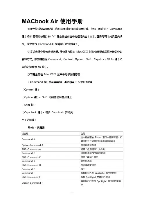
MACbook Air使用手册要使用快捷键或组合键,您可以同时按修饰键和字符键。
例如,同时按下Command 键(标有符号的按键)和“c”键会将当前选中的任何内容(文本、图形等等)拷贝至夹纸板。
这也称作Command-C 组合键(或快捷键)。
许多组合键中都包含修饰键。
修饰键将改变Mac OS X 对其他按键或鼠标点按动作的解释方式。
修饰键包括Command、Control、Option、Shift、Caps Lock 和fn 键(如果您的键盘有fn 键)。
以下是出现在Mac OS X 菜单中的修饰键符号:(Command 键)也叫苹果键,基本相当于pc的Ctrl键(Control 键)(Option 键)-“Alt”可能也出现在此键上(Shift 键)(Caps Lock 键)- 切换Caps Lock 开或关fn(功能键)Finder 快捷键应用程序和其他Mac OS X 键盘命令注:有些应用程序可能不支持以下所有应用程序组合键。
(*) 注:如果未选择任何文本,则从插入点位置开始扩展。
如果通过拖移选择文本,则从所选内容的边缘开始扩展。
反向选择所选内容会取消选择相应部分。
万能辅助- VoiceOver 键盘命令有关Mac OS X v10.6 中VoiceOver 组合键差异的信息,请参阅此文章。
注:您可能需要在“键盘”偏好设置中启用“将F1、F2 等键用作标准功能键”,才能使VoiceOver 菜单和实用工具正常工作。
万能辅助- 鼠标键在“万能辅助”偏好设置中打开鼠标键后,您便可以使用键盘或数字小键盘上的键移动鼠标指针。
如果电脑没有数字小键盘,请使用Fn(功能)键。
另请参阅:鼠标快捷键。
其他信息高级:本文所指为默认的修饰键分配。
可在系统偏好设置的“键盘与鼠标”偏好设置中更改修饰键分配。
例如,您可以将Command 键改为用作Option 键,反之亦然。
您也可以恢复默认修饰键设置。

苹果mac-操作系统基本操作教程————————————————————————————————作者: ————————————————————————————————日期:苹果操作系统基本操作教程一、系统及桌面。
1)桌面组成:苹果菜单、功能菜单、硬盘、文件(夹)、控制条、垃圾桶。
注:桌面上面所有可以被选择的东西,象文件、文件夹、硬盘、垃圾桶等统称为物件。
ﻫ如发现菜单上有些功能项目反白且不能被选择,是因为没有在桌面上选择物件。
2ﻫ)苹果单键鼠标的使用:单击、双击打开、双击浏览、拖放、多选、任意多选(SHIFT键);按Ctrl键光标旁会出现“目”符号,再单击鼠标会出现下拉式功能菜单(相当于PC机的右键)。
3ﻫ)窗口控制:打开、关闭、移动、缩放、最大化、卷缩、缩成标签。
4)文件和文件夹:作用、建立、删除、拷贝。
5)更改文件和文件夹的名字:选中物件—> 按回车进入编辑状态—>输名字(Command+Z可还原)—> 确认ﻫ6)中英文切换和选输入方法:COMAMND+SPACE 或在右上角的菜单里选7)软盘和CD-ROM的使用:弹出盘片:Command+Y 、Command+E或把盘符拖曳到垃圾桶8)硬盘(Macintosh HD)的内容:ﻫDTP文件夹:装有Photoshop、Freehand、Illustator、Pagemaker等设计软件TOOLS文件夹:装有Diskinfectant(杀毒)、HDT(MO驱动)、NDD(磁盘医生)、CLK(中文支持挂件)等工具软件。
ﻫSystem Folder文件夹:整个操作系统的核心。
9)完整的系统组成:ﻫ[原装英文系统+CLK (中文支持)+ 字体 + 设计及工具软件+外设驱动] ﻫ10)查看电脑软硬件资源,如硬盘、内存容量、系统版本等等: ﻫ—> 点击苹果菜单下苹果系统概述ﻫ二、功能菜单及控制条的使用。
1)FILE(文件):NEWFOLDER(新文件夹),GET INFO(简介),MAKE ALIAS(建立替身),FIND(查找),LABEL(标签) ﻫ NE WFOLDER(建立文件夹):建立一个新的文件夹,您可以改变它的名字和图标。

小白的2014新款13寸macbook air开箱晒单迫于若干细心又较真的值友苦苦相逼,小白不得不修改下,把满篇因为懒惰而没有加上的m ac的os系统修改为苹果系统,英文不能瞎秀呀,央视都把NBA称为美职篮了,那我也就直白的苹果系统吧!我叫小白,也是新手小白,一直是什么值得买的忠实粉丝,看着大家精美的晒物图片一直是羡慕嫉妒的口水直流。
可是因为本人非常懒惰,又没有什么摄影技巧,所以也没好意思出来献丑,主要是觉得没什么可晒的商品,刚好今天mac到手随手拍了几张,这里献丑了。
其实我也不是什么果粉,只是怕麻烦的屌丝一枚,刚开始入手爱疯3gs的时候还觉得仿佛有那么点优越感,因为登陆qq的时候旁边有一个来自iphone客户端的标志略显逼格,也愿意刷机越狱的鼓捣,而现在公交车上拿最新款的iphone6也是越来越多啦,所以根本懒得鼓捣,但是电话还是选择爱疯只是因为它够简单又轻便。
入手过iphone系列3gs,4,5 s,ipad系列2和air,今天又迎来了macbook air,奥,对,还有两个ipod,早已不知道在哪里落灰呢!终于知道为什么上班这么多年没攒下钱的原因了,都买苹果了,略桑心言归正传,开始晒物。
13寸128g国行版本,信用卡分期十二期无手续费,还行吧,本来想买港行,可是还是有些不放心,毕竟某宝水太深,笔记本算大件电子设备了,还是谨慎些吧!Apple MacBook AirMD760CH/B 13.3英寸宽屏笔记本电脑¥6588京东下面开始上图啦!心太急,拆外包装纸箱的时候就没有拍照。
直接从包装盒开始吧。
一如所有苹果设备外包装一样,简洁、干净。
从图片也能看的出它惊人的纤薄程度。
侧面唯一的标识,显示身份。
背面各种设备信息,13寸屏幕,i5处理器,4GB内存,128G固态硬盘,国行,话说就这个价格来说配置真心一般,但是苹果就是苹果,工业设计无可比拟,卖的就是设计吧!打开包装盒盖,当当当当,主角登场,铝制外壳在灯光下泛出金属的光泽,被咬了一口的苹果在正中央吸引眼球。
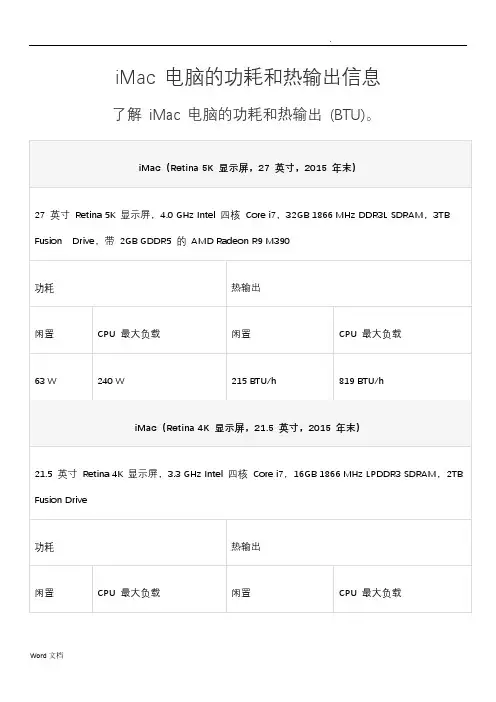
iMac 电脑的功耗和热输出信息了解iMac 电脑的功耗和热输出(BTU)。
iMac(24 英寸,2009 年初)
24 英寸显示器,3.06GHz Intel Core 2 Duo,4GB 1066MHz DDR3 SDRAM - 2x2GB,1TB 串行ATA 硬盘驱动器,ATI Radeon HD 4850 显卡
功耗热输出
闲置CPU 最大负载闲置CPU 最大负载
125.5 W 215.7 W 426.7 BTU/h 733.4 BTU/h
备注
1.功耗数据(瓦特)是在连接墙壁电源插座时测量的,包括全部电源及系统损耗。
无
需额外校正。
2.“CPU 最大负载”定义的是运行计算密集型测试应用程序而处理器使用率最高时的功
耗。
3.这些数值反映的是环境温度为23°C (73.4° F) 时的运行状况。
环境温度越高,风扇
转速越快,功耗也就越大。
在35° C (95° F) 时,功耗增加50 W。
4.仅供教育机构使用。
*信息不详。
上次修改时间:2015-10-29
有帮助?
是否
Apple Footer
Apple
1.支持
2.iMac 电脑的功耗和热输出信息
更多选购方式:前往Apple Store 零售店、拨打400-666-8800 或查找经销商。
Copyright © 2016 Apple Inc. 保留所有权利。
隐私政策使用条款销售和退款站点地图联系Apple
中国(简体中文)。
电脑的了解第一台1946年诞生在宾夕法尼亚大学性能运算速度每秒5000次加法 400次乘法1.外观:主机显示器键盘鼠标音响等外设电脑的组成:硬件系统:主板CPU 内存硬盘显卡声卡...2 系统结构软件系统:系统软件应用软件Cpu:中央处理器(类似于人的大脑思考一样)Cpu目前分为两类品牌分别是英特尔和AMD英特尔现在最高级别系列是;酷睿 I 系列分别为 I3 I5 I7 都是第三代处理器CPU主频:cpu主频也称工作频率 CPU主频越高,计算运行速度就越快、内存:主存储器(类似于人的神经一样)内存分别为1代 333 4002代 667 8003代 1066 1333 1600主板:电脑中最大的一块电路板集成了周边设备的接头(类似于人的神经系统)主板上有声卡网卡芯片组;构成主板电脑的核心北桥:就是主板上离cpu 最近的一块芯片负责就是CPU和内存相连南桥:负责管理设备接口的控制器硬盘:存储器负责储存音乐硬盘以及文件1KB=1024b1MB=1024KB1GB=1024mb显卡:又被称为视频卡图显卡负责将CPU送来的影像数据处理成显示器认识的格式现在在显示器上。
Macos现在疯狂肆虐的电脑病毒几乎都是针对Windows的,由于MAC的架构与Windows不同,所以很少受到病毒的袭击。
MAC OSX操作系统界面非常独特,突出了形象的图标和人机对话(图形化的人机对话界面最初来自施乐公司的Palo Alto研究中心,苹果借鉴了其成果开发了自己的图形化界面,后来又被微软的Windows所借鉴并在Windows中广泛应用)。
苹果公司能够根据自己的技术标准生产电脑、自主开发相对应的操作系统,可见它的技术和实力非同一般。
打个比方,苹果公司就像是Dell和微软的联合体,在软硬件方面“才貌双全”。
现有mac系统后有 windowsMacBook Air在美国的发布会上乔布斯是从一个牛皮纸袋中拿出MBA的,这一举动非常酷,不仅给现场的观众也给稍后看到报道的用户很大的震撼,随后推出的MBA广告也是结合牛皮纸带来作的,让我们不得不佩服苹果策划人员的无限创意。

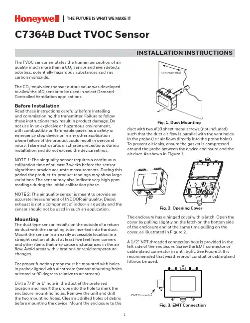
THE FUTURE IS WHAT WE MAKE ITC7364B Duct TVOC SensorINSTALLATION INSTRUCTIONSThe TVOC sensor emulates the human perception of air quality much more than a CO 2 sensor and even detects odorless, potentially hazardous substances such as carbon monoxide.The CO 2-equivalent sensor output value was developed to allow the IAQ sensor to be used in select Demand Controlled Ventilation applications.Before InstallationRead these instructions carefully before installing and commissioning the transmitter. Failure to follow these instructions may result in product damage. Do not use in an explosive or hazardous environment, with combustible or flammable gases, as a safety or emergency stop device or in any other application where failure of the product could result in personal injury. Take electrostatic discharge precautions during installation and do not exceed the device ratings.NOTE 1: The air quality sensor requires a continuous calibration time of at least 3 weeks before the sensor algorithms provide accurate measurements. During this period the product-to-product readings may show large variations. The sensor may also indicate very high ppm readings during the initial calibration phase.NOTE 2: The air quality sensor is meant to provide an accurate measurement of INDOOR air quality. Diesel exhaust is not a component of indoor air quality and the sensor should not be used in such an application.MountingThe duct type sensor installs on the outside of a return air duct with the sampling tube inserted into the duct. Mount the sensor in an easily accessible location in a straight section of duct at least five feet from corners and other items that may cause disturbances in the air flow. Avoid areas with vibrations or rapid temperature changes.For proper function probe must be mounted with holes in probe aligned with air stream (sensor mounting holes oriented at 90 degrees relative to air stream)Drill a 7/8” or 1” hole in the duct at the preferredlocation and insert the probe into the hole to mark the enclosure mounting holes. Remove the unit and drill the two mounting holes. Clean all drilled holes of debris before mounting the device. Mount the enclosure to theduct with two #10 sheet metal screws (not included)such that the duct air flow is parallel with the vent holes in the probe (i.e.: air flows directly into the probe holes). To prevent air leaks, ensure the gasket is compressed around the probe between the device enclosure and the air duct. As shown in Figure 1.The enclosure has a hinged cover with a latch. Open the cover by pulling slightly on the latch on the bottom side of the enclosure and at the same time pulling on the cover, as illustrated in Figure 2.A 1/2” NPT threaded connection hole is provided in the left side of the enclosure. Screw the EMT connector or cable gland connector in until tight. See Figure 3. It is recommended that weatherproof conduit or cable gland fittings be used.Fig. 3. EMT ConnectionThis device has a half-wave type power supply so the power supply common is the same as the output signal common. Therefore, several devices may be connected to one power supply and the output signals all share the same signal common. Use caution when grounding the secondary of an AC transformer or when wiring multiple devices to ensure that the circuit ground point is the same on all devices and the controller.Ensure the controller Analog Input (AI) matches the TVOC voltage output signal type before power is applied. The voltage signals have a minimum loadrating. Follow the ratings in the Specification section or inaccurate readings may result.Connect the LINEAR output signal to a 0-5 or 0-10 Vdc analog input port on the controller as shown in Figure 6. The device is factory configured for 0-5 Vdc output signal but may be changed to 0-10 Vdc via the menu. Changing output signal may be done during set up of the device. This linear output signal represents to 0-2000 ppm CO 2-equivalent value.The ASO (Analog Stepped Output) output signal is a second voltage signal that represents the three air quality levels of GOOD, FAIR, and POOR. Each level may be set independently via the menu to any value between 0 and 10 Vdc. The factory default is GOOD = 2.5 V, FAIR = 5.0 V, and POOR = 7.5 V. This signal canDUCT TVOC SENSORWiring•Deactivate the 24 Vac/dc power supply until all connections are made to the device to prevent electrical shock or equipment damage. Follow proper electrostatic discharge (ESD) handlingprocedures when installing the device or equipment damage may occur•Use 18-22 AWG shielded wiring for all connections and do not locate the device wires in the same conduit with wiring used to supply inductive loads such as motors. Make all connections in accordance with national and local codes.• Connector layout is shown in Figure 5. Diagram shown includes all options. If option is not ordered, connector will not be present.•Connect the positive DC voltage or the hot side of the AC voltage to the terminal marked POWER. The power supply common is connected to the terminal marked COMMON as shown in Figure 6.•The device is reverse voltage protected and will not operate if connected backwards.Fig. 4. Secure CoverFig. 5. PCB LayoutPOWER LINEARCOM PWR ASO LINEARN.O.RELAYUP DOWN MENUTwo security screws are provided which can be installed to help secure the cover once settings and wiringconnections are complete. See Figure 4.Fig. 6. WiringDUCT TVOC SENSORalso be connected to a controller analog input, or it can be connected directly to a 0-5 or 0-10 Vdc input of a damper actuator for direct ventilation control as shown in Figure 7. In this way, the Indoor Air Quality Sensor can be used as a stand-alone device. Since all steps are completely adjustable, the device can also drive a reverse acting actuator.The relay output available on the RELAY terminals. The relay output terminals are completely isolated from other connections and are NOT connected to the signal COMMON terminal as shown in Figure 8. This signal can be used to directly control an alarm, a ventilation fan or may be connected to a digital input of a Building Automation System for status monitoring. Respect the relay contact specification as listed in this document.Set-UpVerify that the TVOC sensor is properly wired and all connections are tight. Apply power to the device and note that the LCD will display the software versionnumber for a few seconds and then the device will enter Warm Up mode. The Warm Up mode will last for five minutes and the LCD will count down the time. This time is required to allow the device and sensor to reach normal operating temperature. After the five minutes has expired the device will enter normal operation and the LCD will indicate the TVOC status and ppm value.OperationIn normal operation, the TVOC sensor will detect a broad range of reducing gases such as CO and VOCs and translate the measurement into a parts per million (ppm) CO 2 equivalent value. This value is displayed on the LCD in either ppm or % as set in the menu. The air quality value is also displayed as either GOOD, FAIR or POOR and these values can also be set via the menu.The GOOD, FAIR and POOR air quality levels control the Analog Stepped Output (ASO) signal. The ASO output signal comprises of three independently set voltage levels that can be used to directly control a damper actuator for three positions. The levels are set via the menu and each level can be set anywhere from 0-10 Vdc. The GOOD, FAIR and POOR air quality levels will also be displayed on the tri-color front panel LED. The LED colors are displayed as GOOD = green, FAIR = blue and POOR = red. If required, the LED operation can be disabled via the menu.The air quality value is also sent to the LINEAR output as a 0-5 or 0-10 Vdc signal to represent the 0-2000 ppm CO 2 equivalent. This signal can interface to any voltage analog input for logging or control purposes.The linear output scaling and ASO operation is shown below. Note that the ASO GOOD/FAIR trip level = 1000 ppm and the FAIR/POOR trip level = 1500 ppm. The ASO output levels are GOOD = 2.5 V, FAIR = 5.0 V and POOR = 7.5 V.The normally open relay will close when the airquality exceeds a pre-set trip point. The trip point and hysteresis value can be programmed via the menu such that the relay closes when IAQ > Relay Setpoint and opens when IAQ < Relay Setpoint - Hysteresis. By default, the relay has a one minute minimum onand off time to prevent short cycling. This feature may be disabled via the menu. The menu may alsobe used to test the relay function. The relay can be used to control an alarm, fan directly or to signal a digital input.Fig. 7. ASO WiringFig. 8. Relay WiringASODUCT TVOC SENSOROther features and configuration are described in the Setup Menu section.NOTE: The air quality sensor requires a continuous burn-time of at least 3 weeks before the sensoralgorithms provide accurate measurements. During this period the product-to-product readings may show large variations. The sensor may also indicate very high PPM readings during the initial burn-in phase.The TVOC sensor is meant to provide an accurate measurements of INDOOR air quality. Diesel exhaust is not a component of indoor air quality and the sensor should not be used in such an application.MenuThe menu may be accessed any time after the initial warm-up period. The menu is controlled by using the three buttons on the PCB labeled UP, DOWN, and MENU. All values entered are saved in non-volatilememory and will be restored correctly in case of a power failure.The menu has several items as shown below. To enter the menu, press and release the <MENU> key while in normal operation. This will enter the User menu step 1, pressing the <MENU> key a second time advances to step 2. Each press of the <MENU> key advances the menu item. The <UP> and <DOWN> keys are used to make changes to program variables by scrollingthrough the available options. When a value is changed, use the <MENU> key to save it to memory and advance to the next menu item. Actual menu displays with the factory default value are shown.NOTE: If no keys are pressed for 2 minutes, the menu will automatically exit.IAQ Unit ppmThe LCD displays the IAQ sensor reading from 450-2000 ppm. Use<UP> or <DOWN> to change from ppm (default) to % for 0-100 % display. 0-100% = 450-2000 ppm. Thissetting has no effect on the LINEAR output signal, it is always scaled 0-2000 ppm = 0-5/0-10 Vdc.<MENU>Press to advance to next menu item1. IAQ UnitIAQ G/F 1000 ppmThis sets the trip point from Good to Fair IAQ for the LED and ASO. Thefactory default is 1000 ppm. Use <UP> or <DOWN> to change from 700 to 1200 ppm in 25 ppm steps.<MENU>Press to advance to next menu item2. IAQ G/F IAQ F/P 1500 ppmThis sets the trip point from Fair to Poor IAQ for the LED and ASO. The factory default is 1500 ppm. Use <UP> or <DOWN> to change from 1300 to 1700 ppm in 25 ppm steps. Note that both IAQ trip points have a 25 ppm hysteresis built in.<MENU>Press to advance to next menu item3. IAQ F/P Analog Out 5VThe LINEAR analog output signaldefaults to 0-5 Vdc. It can be changed with <UP> or <DOWN> to 0-10 Vdc. The selected scale is always equal to 0-2000 ppm.<MENU>Press to advance to next menu item4. Analog Output ASO Good 2.5 VdcThis sets the ASO output voltage for the Good range. It can be set using <UP> or <DOWN> anywhere from 0-10 Vdc. Resolution is 0.1 Vdc. The ASO output changes accordingly.<MENU>Press to advance to next menu item5. ASO Good Output ASO Fair 5 VdcThis sets the ASO output voltage for the Fair range. It can be set using <UP> or <DOWN> anywhere from 0-10 Vdc. Resolution is 0.1 Vdc and ASO out updates.<MENU>Press to advance to next menu item6. ASO Fair Output ASO Poor7.5 VdcThis sets the ASO output voltage for the Poor range. It can be set using <UP> or <DOWN> anywhere from 0-10 Vdc. Resolution is 0.1 Vdc and ASO out updates.<MENU>Press to advance to next menu item7. ASO Poor Output IAQ Cal 0 ppmUse <UP> or <DOWN> to add orsubtract an offset to the IAQ signal. This can change from -200 to + 200 ppm in 10 ppm increments.<MENU>Press to advance to next menu item8. IAQ CalibrationRelay Test OFFRelay SP 1000 PPMUse <UP> or <DOWN> to toggle the relay on or off for testing.Use <UP> or <DOWN> to change the relay setpoint from 750-1500 ppm. Default is 1000. Resolution is 25 ppm.<MENU>Press to advance to next menu item<MENU>Press to advance to next menu item9. Relay Test 10. Relay Set Point Relay Hy 100 PPMRelay Dly YESRelay Op NOCan change the relay hysteresis to 20, 50, 100, or 200 ppm. Default is 100.By default, the relay has a 1 minute minimum on time and a 1 minute minimum off time to prevent fast cycling. This feature can be disabled here.By default, the relay is normallyopen as its non-energized state. Use <UP> or <DOWN> to change to NC (normally closed).<MENU>Press to advance to next menu item<MENU>Press to advance to next menu item<MENU> Exits the User menu and returns the normal operation. The LCD flashes“Menu Exits” for 3 seconds.11. Relay Hysteresis 12. Relay Delay 13. Relay Open/ClosedDimensionsTHE FUTUREIS WHAT WE MAKE IT® U.S. Registered Trademark © 2020 Honeywell International Inc.Printed in Canada 31-00414-01WEEE Directive 2012/19/EC Waste Electrical and Electronic Equipment directiveAt the end of the product life dispose of the packaging and product in a corresponding recycling centre. Do not dispose of the unit with the usual domestic refuse. Do not burn the product.Honeywell Building TechnologiesIn the U.S.:Honeywell715 Peachtree Street NE Atlanta, GA WARNING: This product can expose you to chemicals which are known to the State of California to cause cancer/birth defects or other reproductive harm. For more information go to .。

正如预期,苹果公司在今年对旗下的产品进行了小幅更新。
除了iPhone,Mac产品也获得了最新的英特尔Haswell处理器。
与MacBook Air不同的是,iMac产品在一年前获得了全新的设计,所以2013版看起来依然诱人。
2013版iMac依然拥有21.5英寸和27英寸两种款式,延续了前作的超薄设计,升级了Haswell处理器以及NVIDIA显卡,并内置了更快的802.11 ac WIFI和PCIe SSD固态硬盘。
售价方面,依旧为1299美元(7949元人民币)和1799美元(11009元人民币)起,目前国内行货暂未上架,但是参考中国区苹果在线商店2012款iMac已经全部显示缺货的信息,相信2013版会很快上架。
那么下面,我们还是一起来看看2013版iMac的使用感受如何吧。
外观和感觉苹果iMac的整体设计,可以说是目前一体机产品中最为精湛的。
在去年,iMac得到了一个全新的设计,将之前厚重的屏幕机身缩减到5毫米,框架更加轻薄。
与MacBook Air 不同的是,iMac并非使用了一整块铝合金作为外壳,而是两块,但是你在产品上几乎看不到焊接的痕迹,所以不得不佩服苹果的工业设计能力。
总而言之,这是一款漂亮、精致的一体机,充满了苹果的风格。
接口方面,你可以在机身后面找到耳机、SDXC读卡器、四个USB 3.0、两个Thunderbolt 接口和一个以太网接口,十分全面。
另外,销售包装内依旧包含了无线键盘,你还可以选择Magic Mouse或是Magic Trackpad,如果两个都需要,则需要支付额外的费用。
在这里建议大家选择后者,能够实现更好的手势操作感受,而设计过于怪异的Magic Mouse,基本上无法长时间使用。
一些用户经常会向我们询问到底购买哪款尺寸的iMac更好,其实这完全取决于你的使用场合。
如果是在狭窄的办公环境,不妨选择21.5英寸;如果是在家中拥有充足空间,自然是27英寸。
显示和声音iMac屏幕分辨率分为两种,21.5英寸为1080P全高清,而27英寸版本则拥有更高的2560*1440分辨率。
MACbook Air使用手册要使用快捷键或组合键,您可以同时按修饰键和字符键。
例如,同时按下 Command键(标有符号的按键)和“c”键会将当前选中的任何内容(文本、图形等等)拷贝至夹纸板。
这也称作 Command-C 组合键(或快捷键)。
许多组合键中都包含修饰键。
修饰键将改变Mac OS X 对其他按键或鼠标点按动作的解释方式。
修饰键包括 Command、Control、Option、Shift、Caps Lock 和fn 键(如果您的键盘有fn 键)。
以下是出现在Mac OS X 菜单中的修饰键符号:(Command键)也叫苹果键,基本相当于pc的Ctrl键(Control键)(Option键)-“Alt”可能也出现在此键上(Shift 键)(Caps Lock 键)- 切换Caps Lock 开或关fn(功能键)应用程序和其他Mac OS X 键盘命令(*) 注:如果未选择任何文本,则从插入点位置开始扩展。
如果通过拖移选择文本,则从所选内容的边缘开始扩展。
反向选择所选内容会取消选择相应部分。
万能辅助 - VoiceOv er 键盘命令<。
注:您可能需要在“键盘”偏好设置中启用“将F1、F2 等键用作标准功能键”,才能使VoiceOv er 菜单和实用工具正常工作。
万能辅助- 鼠标键在“万能辅助”偏好设置中打开鼠标键后,您便可以使用键盘或数字小键盘上的键移动Fn(功能)键。
另请参阅:鼠标快捷键。
其他信息高级:本文所指为默认的修饰键分配。
可在系统偏好设置的“键盘与鼠标”偏好设置中更改修饰键分配。
例如,您可以将 Command键改为用作 Option键,反之亦然。
您也可以恢复默认修饰键设置。
Macbook air 2013安装windows7,解决鼠标键盘失灵问题的解决方法(集成USB3.0驱动的方法)2014-09-13 14:07 8817人阅读评论(0) 收藏举报Macbook air 2013安装windows7时,会出现在语言选择界面,键盘鼠标均失灵,或者在用户名界面,鼠标键盘失灵。
本文采用的是将USb3.0集成到Windows7的安装盘的方法。
本文为参考/read-htm-tid-6613405-page-1.html,并添加了自己的心得。
步骤;1、在Mac下,运行Bootcamp,执行第二和第三项,第一项不需要选。
原因见说明3。
说明:(1)如果选中第一和第二项,则将使用Win7安装盘的ISO,创建USB盘的Windows7安装盘,并将Bootcamp下载的驱动集成到该usb中。
(2)如果是将整个MAc只安装windows7,完全抹掉MAc,则只需第二项即可。
如果是同时保留Mac和Windows7,则需要使用第三项,进行硬盘分区。
(3)因本文采用的是将USB3的驱动集成到ISO中的方法,因此,如果你有USB的光驱,则第一项可以不需要做。
如果没有,需要使用USB的windows7安装盘,则可使用第一项制作USB格式的Win7安装盘,或者使用其他软件制作USB的安装盘。
但这个ISO必须为按下文所述的方法制作的集成USB3的驱动的ISO。
(4)Bootcamp 5只支持Windows 64,不支持32位的系统。
如需安装32位的Windows7,需要Bootcamp4。
2、完成后的U盘中,其中的bootcamp文件夹为驱动,$WinPEDriver$据说为windows启动时使用的驱动,所以在第一步时,如果选择Bootcamp中的第一步和第二步,则会该文件夹,网上有说使用第一步和第二步解决驱动问题的,但我试用了,没有成功。
最好将整个U盘备份,否则如果需要重装WIndows7 ,需要重新下载该驱动。

Fiery Command WorkStation© 2015 Electronics For Imaging. 此产品的《法律声明》适用于本出版物中的所有信息。
目录概述 (13)Command WorkStation (13)Command WorkStation 工作空间 (13)作业中心 (14)设备中心 (15)添加和连接 Fiery Server (17)访问级别 (17)连接到 Fiery Server (17)添加并连接到 Fiery Server (17)搜索可用的 Fiery Server (18)退出 Fiery Server (18)更改 Fiery Server 的用户 (18)查看其他 Fiery Server (19)服务器列表 (19)自定义 Command WorkStation (22)设置 Command WorkStation 预置 (22)管理作业中心的列 (23)更改列显示 (23)调整列宽度 (23)重新定义窗格和队列大小 (24)重新定义“正在打印”和“正在处理”队列的大小 (24)重新定义“作业摘要”和“服务器列表”窗格的大小 (24)自定义工具栏 (24)默认工具栏图标 (25)配置 Fiery Server 设定 (26)关于 Configure (26)我使用的是哪个版本的 Configure? (26)查找帮助以及有关 Configure 的其他信息 (26)访问基于 Java 的旧版本 Configure 的帮助 (27)访问基于 HTML 的新版本 Configure 的帮助 (27)查看服务器配置设定 (27)将服务器配置保存为文件 (28)打印“服务器配置”页 (28)访问 Configure (28)从 Command WorkStation 访问 Configure (28)从 WebTools 访问 Configure (29)退出 Configure (29)用户与群组 (29)创建新用户 (30)创建群组 (30)将用户添加到现有群组 (31)创建扫描作业的邮箱 (32)从群组中删除用户 (32)更改用户属性 (32)更改群组权限 (33)删除用户或群组 (33)关于备份和恢复 (34)备份或恢复 Fiery Server 设定 (35)管理 Fiery Central 工作流程 (37)关于 Fiery Central (37)连接或断开 Fiery Central 服务器 (37)Fiery Central 服务器工作空间 (38)查看 Fiery Central 作业 (39)自定义 Fiery Central 作业中心 (40)查看或编辑 Fiery Central 许可证 (40)配置 Fiery Central (41)Fiery Central Manager (42)访问 Fiery Central Manager (42)Fiery Central 打印机群组 (42)备份或恢复 Fiery Central (45)使用 Fiery Central Paper Catalog (46)设置 VDP 文件搜索路径 (47)设置 Digital StoreFront 连接 (47)查看作业 (48)Fiery 预览 (48)查看已假脱机、未经处理的作业 (49)页面视图、印张视图和校对视图 (51)“设定”窗格 (52)打开“校对视图” (53)预览中的工具栏图标 (54)预览光栅图 (54)光栅预览中的工具栏图标 (55)在光栅预览中合并页面 (56)VDP 光栅预览 (56)打印 (59)导入要打印的作业 (59)将作业导入打印队列 (59)从外部 Fiery Server存档导入作业 (60)设置打印选项 (60)查看作业属性 (60)“作业属性”窗口中的作业操作 (61)打印选项类别 (62)作业属性中的 Fiery Impose 模板 (62)预设打印设定 (63)服务器预设 (67)从作业移除光栅数据 (70)打印方法 (70)使用纸盘对齐 (70)样本打印 (71)校样打印 (72)按序打印 (73)设置按序打印 (74)在 Configure 中设置按序打印选项 (74)使用 Quick Doc Merge (75)管理作业 (77)搜索作业 (77)使用筛选视图选项卡搜索作业 (77)过滤作业列表 (78)导出作业列表 (78)将作业移至其他队列 (79)将作业发送至另一台 Fiery Server (80)存档作业 (80)拖放文件管理 (81)Fiery JDF 作业 (82)关于 Fiery JDF 和 JMF (82)Fiery JDF 设置 (82)启用 JDF 提交应用程序 (82)Fiery JDF 工作流程 (83)提交 JDF 作业 (83)显示 Command WorkStation 中的 JDF 列标题 (83)Fiery JDF 作业和虚拟打印机 (83)指定作业的 JDF 设定 (84)“作业信息”选项卡 (84)“运行列表”选项卡 (85)“关闭作业”选项卡 (85)将 JDF 作业纸张添加到 Paper Catalog (86)解决 JDF 作业中的纸张冲突问题 (86)Fiery Dashboard (87)创建 EFI 通行证帐户(免费) (87)登录到 Fiery Dashboard (87)Fiery Dashboard 数据收集 (88)授权数据收集 (88)取消数据收集的授权 (88)管理颜色 (89)彩色打印选项 (89)查看或编辑默认颜色设定 (89)特性档 (95)查看特性档属性 (96)比较特性档色域 (96)导入或导出特性档 (96)创建或删除特性档 (98)编辑特性档设定 (99)编辑特性档内容 (99)打印测试页 (101)校准 (pre-System 10) (102)Calibrator 模式 (103)使用 ColorCal 进行校准 (103)使用 ES-1000 进行校准 (105)使用 Eye-One 进行校准 (106)对多个校准集应用测量值 (107)创建或删除自定义校准集 (107)恢复默认测量值 (108)校准(System 10 和更高版本) (108)校准黑白打印 (109)校准工作流程 (109)启动 Calibrator (109)打印校准页 (110)使用分光光度计测量色块 (110)使用 ColorCal 测量色块 (111)从备用测量仪器导入测量数据 (113)查看测量结果 (114)导出测量数据 (115)重设测量数据 (115)Calibrator 预置 (116)校准设定 (117)自定义 Image Enhance 设定 (120)Image Enhance Visual Editor (121)何时使用 IEVE 或 Image Enhance 打印选项 (122)打开大型作业 (122)预设 (122)调整图像 (122)保存对作业的编辑 (122)启动 Image Enhance Visual Editor (123)使用预设 (123)打开大型作业 (124)调整色调 (124)调整颜色 (125)调整清晰度 (126)校正红眼 (127)专色 (127)专色群组和定义 (127)更改专色或颜色组的顺序 (128)查找专色 (129)编辑专色 (129)优化专色 (129)创建、重命名或删除专色或颜色群组 (130)导入和导出自定义颜色群组 (131)查看颜色群组的色域 (131)色版页和色版书 (132)打印专色色板页或色板书 (132)测量和导入专色值 (133)替换颜色 (134)二色打印映射 (135)管理服务器资源 (137)虚拟打印机 (137)创建、编辑或复制虚拟打印机 (137)管理虚拟打印机 (138)从 Windows 打印到虚拟打印机 (139)从 Mac OS 打印到虚拟打印机 (139)Paper Catalog (140)从 Paper Catalog 选择纸张 (141)设置 Paper Catalog (142)管理 Paper Catalog 数据库 (147)纸张属性 (149)常见纸张属性 (149)纸盘关联 (157)纸盘关联显示 (158)将纸张分配给纸盘 (158)智能纸张 (159)监控纸盘中的纸张状态 (161)更改列显示 (161)VDP 资源 (162)管理 FreeForm 主文页 (162)备份 VDP 资源 (163)恢复 VDP 资源 (163)查看并删除全局资源 (164)字体 (164)备份和恢复字体 (165)查看用户和群组权限 (165)访问用户和群组 (166)查看用户和群组权限的详细信息 (166)比较权限 (166)查看或添加群组 (166)访问群组 (167)添加群组 (167)使用作业日志 (167)查看作业日志 (168)打印作业日志 (168)导出作业日志的内容 (168)导出和/或清空作业日志的内容 (169)印刷制版工具 (170)Fiery Graphic Arts 的功能 (170)Fiery Graphic Arts Package (Premium Edition) (170)Fiery Productivity Package (170)控制栏 (171)页面大小和控制栏(FS100/100Pro 或较早版本) (172)默认情况下,在每页打印控制栏 (172)查看和编辑控制栏 (172)创建自定义或重复的控制栏 (173)导出、导入或删除自定义控制栏 (173)恢复出厂默认控制栏设定 (174)陷印 (174)设置所有作业的自动陷印 (174)指定陷印宽度 (175)指定陷印颜色减少 (175)指定陷印形状 (175)指定陷印对象类型 (175)进度 (176)查看或编辑进度设定 (176)校样半色调模拟 (176)查看或编辑自定义半色调网屏 (177)纸色模拟白点编辑 (177)编辑纸色模拟白点值 (178)配置和运行预检 (179)ImageViewer (179)启动 ImageViewer (180)调整图像预览 (180)调整图像的大小 (181)查看图像中的颜色值 (181)显示分色 (181)使用曲线编辑颜色响应或灰度响应 (182)使用颜色轮编辑颜色 (183)通过图像编辑灰度响应曲线 (183)将颜色编辑应用于一个或所有页面 (183)通过本地文件应用颜色编辑 (184)通过服务器预设应用颜色编辑 (184)应用 Curve2/Curve3 文件的颜色曲线 (185)应用灰度响应曲线编辑 (185)打印含编辑内容的作业 (186)将软校样导出为 PDF 格式 (186)比较显示器特性档和输出特性档 (187)在 Fiery Server 上安装当前编辑 (187)在 Fiery Server 上恢复出厂默认响应曲线 (188)设置 ImageViewer 预置 (188)Booklet Maker (189)Booklet Maker 拼版 (189)关于 Booklet Maker 和 Fiery Impose (189)访问 Booklet Maker (189)从打印机驱动程序 访问 Booklet Maker (190)在 Command WorkStation 中访问 Booklet Maker (190)创建小册子 (190)从 Booklet Maker 窗口创建小册子 (190)从 Booklet Maker 向导创建小册子 (191)小册子类型 (192)鞍式装订 (193)套叠式鞍式装订 (194)胶装 (195)一合一 胶装 (196)纸张大小 (197)缩小文档页面大小以适合所选的纸张大小 (198)“缩小至适合”选项 (199)页面对齐 (203)对齐页面 (203)页面对齐和装订线 (206)爬移补偿 (208)采用一合一胶装的混合纸张 (208)在 Booklet Maker 中指定混合纸张设定 (209)在混合纸张中浏览作业 (210)以页面形式查看作业的版面 (210)以印张形式查看作业的版面 (210)Booklet Maker 混合纸张限制 (211)添加 封面 (211)在应用程序中更改文档大小 (212)更改测量单位 (212)预览小册子 (213)小册子工作流程示例 (213)打印胶装小册子 (213)打印鞍式装订小册子 (213)打印套叠式鞍式装订小册子 (214)Booklet Maker 限制 (214)Booklet Maker 词汇表 (215)索引 (219)概述Command WorkStationCommand WorkStation 是 Fiery Server的打印作业管理界面。
使用手册版权声明爱数软件有限公司©2009 版权所有,保留一切权利。
未经本公司书面许可,任何单位或个人不得以任何形式,复制、传播、摘抄本书内容的 部分或全部。
本手册内容上可能会有增删和修改,爱数软件会定期将修订后的内容纳入新版本中,如 有更改恕不另行通知。
2使用手册关于爱数爱数,直译爱护数据。
作为业界安全备份 的唯一倡导者和中国数据备份整体方案的领先提供商,我们立志于 通过自主创新为用户提供安全可靠的磁盘备份方案,专注于为用户提供全面、统一、安全的 整体网络备份方案和远程容灾服务。
目前,爱数的各项产品和服务在制造业、金融业、医疗业、教育业等大量行业用户中的 成功应用。
了解爱数软件更多信息请访问: 。
爱数软件有限公司地址:上海市闵行区联航路 1188 号浦江智谷 10 号楼 2 层 邮编:201 112 网址: 客户服务电话:021-******** 客户服务邮箱:support@3使用手册目录关于爱数 ................................................................................................................................................ 3爱数备份软件 3.0 简介 ..................................................................................................................... 81. 关于爱数备份软件 3.0..................................................................................................... 82. 爱数备份软件 3.0 的新增功能....................................................................................... 83. 爱数备份软件 3.0 的工作方式........................................................................................ 9 4. 产品组成 ............................................................................................................................ 9 5.基本模块构成与模块功能 ............................................................................................... 95.1 管理控制台 ............................................................................................................. 10 5.2 LDAP 助手.............................................................................................................. 11 5.3 介质服务器 ............................................................................................................. 12 5.4 Windows 客户端 .................................................................................................. 12 5.5 Linux 客户端.......................................................................................................... 13 5.6 系统恢复环境 ......................................................................................................... 13 安装与配置 .......................................................................................................................................... 131. 系统要求 .......................................................................................................................... 13 1.1 32 位管理控制台&介质服务器........................................................................... 13 1.2 64 位管理控制台&介质服务器........................................................................... 14 1.3 32 位 Windows 客户端..................................................................................... 14 1.4 64 位 Windows 客户端..................................................................................... 15 1.5 32 位 Linux 客户端.............................................................................................. 15 1.6 64 位 Linux 客户端.............................................................................................. 16 1.7 LDAP 助手.............................................................................................................. 162. 如何使用 AnySetup....................................................................................................... 16 2.1 检测环境 ................................................................................................................... 17 2.2 安装指导 ................................................................................................................... 18 2.3 查看自述文件 ........................................................................................................... 183. 软件安装管理 .................................................................................................................. 19 3.1 管理控制台安装、配置与卸载 .............................................................................. 19 3.2 介质服务器的安装、配置和卸载.......................................................................... 244使用手册3.3 Windows 客户端安装、配置与卸载.................................................................... 26 3.4 LDAP 助手的安装、配置和卸载 ........................................................................... 32 3.5 Linux 客户端的安装、配置和卸载 ....................................................................... 34 3.6 系统恢复环境的安装 ............................................................................................ 35爱数备份软件管理 ............................................................................................................................. 371. 登录管理控制台 ............................................................................................................ 37 2. 用户管理 ........................................................................................................................ 382.1 创建和管理用户.....................................................................................................38 2. 2 创建和管理用户组.................................................................................................. 38 2.3 用户权限设置 ........................................................................................................... 39 3. 客户端管理 ...................................................................................................................... 41 3.1 客户端(组)操作................................................................................................. 41 3.2 客户端配置 ............................................................................................................. 41 3.3 删除客户端 ............................................................................................................. 42 4. 双机/集群管理 ................................................................................................................ 42 5. 介质服务器 ...................................................................................................................... 43 5.1 介质操作 ................................................................................................................. 43 5.2 介质服务器操作.....................................................................................................44 6. 许可证管理 ...................................................................................................................... 45 6.1 添加和删除授权码................................................................................................... 45 6.2 激活授权码 ............................................................................................................. 45 6.3 许可证授权管理.....................................................................................................45 7. 系统设置........................................................................................................................... 46 8. 更新管理 .......................................................................................................................... 47 8.1 更新管理界面 ......................................................................................................... 47 8.2 更新管理操作 ........................................................................................................... 48基本功能操作...................................................................................................................................... 491. 基本功能操作 .................................................................................................................. 49 1.1 备份操作 ................................................................................................................... 49 1.2 创建任务和设置任务选项 ...................................................................................... 50 1.3 备份文档 ................................................................................................................... 52 1.4 备份操作系统 ........................................................................................................... 53 1.5 备份邮件数据 ........................................................................................................... 542. 恢复操作 .......................................................................................................................... 542.1 浏览恢复 ................................................................................................................... 55 2.2 下载恢复 ................................................................................................................... 55 2.3 搜索恢复 ................................................................................................................... 565使用手册3. 执行操作 .......................................................................................................................... 573.1 常规执行任务 ........................................................................................................... 57 3.2 历史清单 ................................................................................................................. 57 3.3 日志管理 ................................................................................................................... 58 3.4 报表管理 ................................................................................................................... 58 应用功能操作...................................................................................................................................... 591. SQL SERVER 备份与恢复............................................................................................... 591.1 功能介绍 ................................................................................................................. 59 1.2 备份注意事项 ......................................................................................................... 60 1.3 备份指导 ................................................................................................................. 60 1.4 恢复指导 ................................................................................................................. 63 1.5 常见问题总结 ......................................................................................................... 65 2. Oracle 备份与恢复.......................................................................................................... 672.1 功能介绍 ................................................................................................................... 67 2.2 备份注意事项 ........................................................................................................... 67 2.3 备份指导 ................................................................................................................... 68 2.4 恢复指导 ................................................................................................................. 71 2.5 常见问题 ................................................................................................................. 74 3. Exchange Server 备份与恢复....................................................................................... 773.1 功能介绍 ................................................................................................................... 77 3.2 备份指导 ................................................................................................................. 77 3.3 恢复指导 ................................................................................................................... 79 3.4 恢复后注意事项.....................................................................................................80 3.5 常见问题处理 ........................................................................................................... 81 4. Lotus Domino 备份与恢复 ........................................................................................... 844.1 功能介绍 ................................................................................................................... 84 4.2 备份注意事项 ........................................................................................................... 85 4.3 备份指导 ................................................................................................................. 86 4.4 恢复指导 ................................................................................................................. 88 4.5 常见问题 ................................................................................................................. 89 5. Sybase 备份与恢复 ......................................................................................................... 905.1 功能介绍 ................................................................................................................... 90 5.2 备份注意事项 ........................................................................................................... 906使用手册5.3 备份指导 ................................................................................................................... 90 5.4 恢复指导 ................................................................................................................... 93 5.5 常见问题 ................................................................................................................. 95 6. Active Directory 备份与恢复........................................................................................ 96 6.1 功能介绍 ................................................................................................................... 96 6.2 备份注意事项 ........................................................................................................... 96 6.3 备份指导 ................................................................................................................. 97 6.4 恢复指导 ................................................................................................................... 99 6.5 常见问题 ...............................................................................................................100 7. 实时备份 ........................................................................................................................ 101 7.1 功能介绍 ...............................................................................................................101 7.2 备份指导 ...............................................................................................................101 7.4 恢复指导 .................................................................................................................103 恢复系统 ............................................................................................................................................104 1.启动系统恢复环境 .......................................................................................................... 104 1.1 硬盘启动 ...............................................................................................................104 1.2 光盘启动 ...............................................................................................................104 1.3 USB 设备启动 ......................................................................................................104 2. 恢复系统 ........................................................................................................................ 105 2.1 手动恢复系统 .......................................................................................................105 2.2 自动恢复系统 .......................................................................................................106 2.3 裸机恢复 ...............................................................................................................106 技术支持 AnySupport ................................................................................................................108 FAQ.....................................................................................................................................................1087使用手册爱数备份软件 3.0 简介1. 关于爱数备份软件 3.0作为业界安全备份的唯一倡导者和国内数据备份整体方案的领导者,上海爱数软件有限 公司专注于备份软件的技术研究和产品开发,提供的解决方案涵盖企业级备份软件、软硬件 一体化方案、远程数据灾备平台、在线备份服务等,立志通过自主创新为用户提供整体网络 备份方案和远程容灾服务。
Macbook air 2013安装windows7,解决鼠标键盘失灵问题的解决方法(集成USB3.0驱动的方法)2014-09-13 14:07 8817人阅读评论(0) 收藏举报Macbook air 2013安装windows7时,会出现在语言选择界面,键盘鼠标均失灵,或者在用户名界面,鼠标键盘失灵。
本文采用的是将USb3.0集成到Windows7的安装盘的方法。
本文为参考/read-htm-tid-6613405-page-1.html,并添加了自己的心得。
步骤;1、在Mac下,运行Bootcamp,执行第二和第三项,第一项不需要选。
原因见说明3。
说明:(1)如果选中第一和第二项,则将使用Win7安装盘的ISO,创建USB盘的Windows7安装盘,并将Bootcamp下载的驱动集成到该usb中。
(2)如果是将整个MAc只安装windows7,完全抹掉MAc,则只需第二项即可。
如果是同时保留Mac和Windows7,则需要使用第三项,进行硬盘分区。
(3)因本文采用的是将USB3的驱动集成到ISO中的方法,因此,如果你有USB的光驱,则第一项可以不需要做。
如果没有,需要使用USB的windows7安装盘,则可使用第一项制作USB格式的Win7安装盘,或者使用其他软件制作USB的安装盘。
但这个ISO必须为按下文所述的方法制作的集成USB3的驱动的ISO。
(4)Bootcamp 5只支持Windows 64,不支持32位的系统。
如需安装32位的Windows7,需要Bootcamp4。
2、完成后的U盘中,其中的bootcamp文件夹为驱动,$WinPEDriver$据说为windows启动时使用的驱动,所以在第一步时,如果选择Bootcamp中的第一步和第二步,则会该文件夹,网上有说使用第一步和第二步解决驱动问题的,但我试用了,没有成功。
最好将整个U盘备份,否则如果需要重装WIndows7 ,需要重新下载该驱动。
Quick Start GuideWelcome to your MacBook AirLet’s begin. Press the power button to start up your Mac, and Setup Assistant guides you through a few simple steps to get you up and running. It walks you through connecting to your Wi-Fi network and creating a user account. And it can transfer your documents, photos, music, and more to your new Mac from another Mac or PC.You can sign in with your Apple ID in Setup Assistant. This sets up your account in the Mac App Store and the iTunes Store, and in apps like Messages and FaceTime. It also sets up iCloud, so apps such as Mail, Contacts, Calendar, and Safari all have your latest information. If you don’t have an Apple ID, you can create one in Setup Assistant.SDXCTransfer photos from yourcamera’s memory card MagSafe 2Magnetically attachthe power cordThunderbolt 2Connect external displays and high-performance devicesUSB 3Charge devices, connect external storage, and more FaceTime HD camera PowerbuttonMulti-Touch trackpadGet to know your desktopYour Mac desktop lets you find everything and do anything. Keep theapps you use most in the Dock at the bottom of the screen. Open System Preferences to customize your desktop and other settings. Click the Finder icon to get to all your files and folders.The menu bar at the top provides useful information about your Mac. To check the status of your wireless Internet connection, click the Wi-Fi icon. Spotlight lets you find anything on your Mac or look up information online. It can also open your favorite apps.Help menu Menu barFinder Dock System PreferencesControl your Mac with Multi-Touch gesturesYou can do a lot on your MacBook Air using simple gestures on the trackpad. Here are some popular gestures. To learn more, choose System Preferences in the Dock, and then click Trackpad.ClickPress anywhere on the trackpad.Secondary click (right click)Click with two fingers to open shortcut menus.Two-finger scrollBrush two fingers along the trackpad to scroll up,down, or sideways.Swipe to navigateSwipe with two fingers to flip through webpages,documents, and more.Back up your dataYou can wirelessly back up your MacBook Air using Time Machine withan AirPort Time Capsule (sold separately). Open System Preferences and click the Time Machine icon to get started.An important notePlease read this document and the safety information in the Important Product Information guide carefully before you first use your computer. Learn moreTo view the MacBook Air Essentials guide in iBooks, open iBooks, then search for “MacBook Air Essentials” in the iBooks Store. You can also find information, watch demos, and learn about MacBook Air features at /macbook-air.HelpYou can find answers to your questions, as well as instructions and troubleshooting information, in Mac Help. Click the Finder icon, clickHelp in the menu bar, and choose Mac Help or “Get to know your Mac.”OS X UtilitiesIf you have a problem with your Mac, OS X Utilities can help you restore your software and data from a Time Machine backup or reinstall OS Xand Apple apps. If your Mac detects a problem, open OS X Utilities by restarting your computer while holding down the Command and R keys. SupportVisit /support/macbookair for MacBook Air technical support. Or call 1-800-275-2273. In Canada, call 1-800-263-3394.Not all features are available in all areas.TM and © 2015 Apple Inc. All rights reserved. Designed by Apple in California.Printed in XXXX. 034-00507-B。
MAC的睡眠模式介绍因为之前⽤的是⽹上流传的⼟法来禁⽌⽣成 sleepimage,尝到了苦头,⽽且2次!⼤家知道 OSX 有⼏种睡眠模式,其中 hibernatemode 可以是 0 (传统睡眠⽅式,不⽣成 sleepimage ⽂件),3 和 25 (Apple 称之安全睡眠⽅式,会⽣成 sleepimage ⽂件),⼤家也都知道可以⽤ sudo pmset -a hibernatemode 0 来禁⽌那个内存镜像⽂件。
以前这个命令⼀直可⽤,直到 OS X Mountain Lion v10.8.2,⼤家突然发现这个命令不起作⽤了,重启电脑或者睡眠⼀段时间后,那个sleepimage ⼜回来了。
换句话说,某些型号的 mac,似乎强制使⽤安全睡眠⽅式。
然后⽹上就有各种⼟法,粗暴之极,诸如建⽴⼀个只读的空⽂件,或者⽤ sudo ln -s /dev/null /var/vm/sleepimage 把内存镜像引⼊系统⿊洞。
这些⼟法,⼀般⽤⽤⼤概没什么问题,就算有问题,你⼤概也不会太在意,譬如程序崩溃,⼤不了重新启动好了。
我之前就是⽤ /dev/null 这个⽅法,然后我2次系统升级都出问题,2个⽉前 10.9.2 升级到 10.9.3 时,以及昨天 10.9.3 升级到 10.9.4 时,升级安装界⾯2次都停留在同⼀个地⽅,说还有⼏分钟就好了,然后,然后,就没有然后了,等了⼀个多⼩时,状态条动都不动。
不得已强⾏关机。
因为我没弄其他任何所谓的系统调试东西,唯⼀运⾏过的 sudo 命令就是这个,所以怀疑是这个⼟法导致升级出错。
然后就觉得要花点时间弄明⽩ OSX 的睡眠⽅式,如果真不能禁⽌ sleepimage,死也要死得明⽩。
以下是我的理解,绝对不同于各⼤中⽂ Mac ⽹站抄来抄去的那些东西。
欢迎探讨。
OSX 的睡眠参数,可以打 pmset -g 了解⼀下你的电脑处在什么睡眠模式下:⽐较有兴趣的参数:standbydelay 10800standby 0autopoweroffdelay 14400autopoweroff 0hibernatemode 0这⼏个参数组成了 OSX 的睡眠模式。