Fotodiox发布新款Pro DLX Stretch镜头转接环
- 格式:pdf
- 大小:599.84 KB
- 文档页数:1


01[套件分解图]02[功能介绍]<背面><正面><底部>后顶板顶板右侧臂左侧臂底板<顶部><左/右侧臂>[R E D KO M O D O -X 拓展套件]�/�定位螺纹孔M�螺纹孔(可安装镜头转接环支撑)(可安装供电模块连接件)[可安装可折叠上手提(TA-T��-FTH-B)][可安装Komodo迷你遮光罩(TA-T��-MSH)][可安装侧臂单孔导轨卡件(TA-SRA-��-B)]M�螺纹孔(连接后顶板)M�螺纹孔M�机身固定孔牙盘接口�/�定位螺纹孔M�机身固定孔(连接底板)M�螺纹孔�/�螺纹孔NATO滑条�/�定位螺纹孔�/�定位螺纹孔M�机身固定孔�/�定位螺纹孔M�螺纹孔M�螺纹孔�/�机身固定孔冷靴接口�/�螺纹孔�/�螺纹孔�/�机身固定孔�/�机身固定孔�/�螺纹孔同时可用硬币替换使用)一字螺丝扳手(可磁吸附于底部的拆卸工具,L型六角扳手(可磁吸附于底部的拆卸工具)1234 5 6 7 8 9 10 1112 13 14 15 16 17 18 19 2022 24 25 2621 23 212223252426456781213111091415161718192012�/�*�*�.�mm M�*�*�mm �/�*�mm�/�*�.�*�.�mm1234111112343ESR-T��-THE(选配)ESR-T��-IOM(选配)TA-RF-PL�(选配)ESR-T��-BP-AB(选配)ESR-T��-BP-V(选配)301[OVERVIEW]02[FUNCTIONS]<BACK><FRONT><BOTTOM>Rear Top Plate Top PlateRight Side ArmLeft Side ArmBottom Plate232524212226<TOP>145678121311109<LEFT/RIGHT SIDE ARM>[CAMERA CAGE FOR RED KOMODO-X]FOR RED KOMODO X1/4”-20(9*5.5mm)M4(8*4mm)1/4”-20(8mm)3/8”-16(9.5*6.5mm)141516171819201/4”-20 Thread with Locating Points[For mounting 15mm Side Single Rod Holder (TA-SRA-15-B)][For mounting Foldable Top Handle (TA-T53-FTH-B)][For mounting Mini Sunhood for RED Komodo (TA-T08-MSH)]234 5 6 7 8 9 10 1112 13 14 15 16 17 18 19 2022 24 25 2621 23 M4 Thread (For mounting lens adapter support)(For mounting battery plate security attachment)M4 Thread (For mounting back top plate)M4 Thread M4 Security Thread Rosette1/4”-20 Thread with Locating PointsM4 Security Thread(For mounting bottom plate)M4 Thread 1/4”-20 Thread NATO Rail3/8”-16 Thread with Locating Points1/4”-20 Thread with Locating Points M4 Security Thread1/4”-20 Thread with Locating PointsM4 Thread M4 Thread1/4”-20 Security Thread Cold Shoe Receiver 1/4”-20 Thread1/4”-20 Thread 1/4”-20 Security Thread 3/8”-16 Security Thread 3/8”-16 Threadbottom of the camera cage. Can be replaced by a coin.)Flathead Screwdriver (Magnetic and detachable on theHex Key(Magnetic and detachable on the bottom of the camera cage.)123412ESR-T08-THE (OPTIONAL)TA-RF-PL2(OPTIONAL)ESR-T08-BP-AB(OPTIONAL)ESR-T08-BP-V(OPTIONAL)ESR-T08-IOM(OPTIONAL)1111123433。

•Interconnects ARRIS digital transport devices–Media converter access products for links up to 40 km–Selected node ‐based Digital Transceivers (models DT4xxxN and DT4250N) for links up to 40 km–Enables Ethernet drops from fiber node platforms •Up to 2.125 Gbps bi ‐directional data links •Small Form Factor Pluggable (SFP)•Duplex LC connector •Very low jitter•Metal enclosure for lower EMI• 3.3 V power supply with low power dissipation •Extended operating temperature rangeThe TR4000‐PI and TR4040‐PI Optical Transceiver Modules feature capabilities for high ‐speed bi ‐directional communications required for ARRIS digital networking products. These SFP modules are functionally identical to the transceivers already built into many ARRIS products, but provide a flexible, plug ‐in means of enabling additional optional secondary ports in several of those products.Conforming to the Small Form Factor Pluggable (SFP) Multisource Agreement, these state ‐of ‐the ‐art components are designed expressly for high ‐speed bi ‐directional communication applications that support rates of up to 2.125 Gbps, with the laser transmission portion of the device operating at a wavelength of 1310 nm.PRODUCT OVERVIEWFEATURESSFP Fiber Optic TransceiversTR40x0‐PI2.125 Gbps 1310 nm Optical TransceiverModulesThese transceivers feature a very low jitter contribution, resulting in extremely clean, high‐quality eye patterns. The SFP metal enclosures not only makes them sturdier, but also improves their FCC test margins. This emission and ESD control is particularly important in applications with sensitive multiport hubs and switches. The modules operate at extended voltage (3.15 to 3.6 V)and temperature (–40°to +85°C) ranges, and all modules are supplied with a duplex LC connector.The TR4000‐PI SFP transceiver supports optical links up to 10 km and the TR4040‐PI supports optical links up to 40 km. These transceivers can be ordered as optional primary or secondary plug‐in modules to support the capabilities of digital transmitter units in NC4000 series nodes such as the legacy DT4xxx‐00/01 Digital Transceivers and the DT4250N Universal Digital Transceiver.The TR40x0‐PI series SFP transceivers may also be used to populate the primary network and local ports of the DS4004 Optical Ethernet Multiplexer for NC4000 series nodes, and are used on other products as described on individual product data sheets.SPECIFICATIONSCharacteristics SpecificationPhysicalDimensions 2.2” L x 0.4” H x 0.5” W (5.6cm x 1.0cm x 1.3cm)Weight0.1 lbs (0.05 kg)EnvironmentalApplication temperature range–40°to +85°C (–40°to +185°F)Storage temperature range–40°to +85°C (–40°to +185°F)Humidity5% to 95% non–condensingOptical InterfaceOptical connectors Duplex LCPower requirementsInput voltage 3.3 V DC(250 mA max)Power consumption•TR4000‐PI: 1.0 W•TR4040‐PI: 1.1 WGeneralSupported link length•TR4000‐PI: 10 km (on SMF‐28 or equivalent)•TR4040‐PI: 40 km (on SMF‐28 or equivalent)Data rate 2.125 GbpsHot plug–in/outOpticalTransmitter TR4000‐PI TR4040‐PITransmitter type Fabry‐Perot DFBCenter wavelength (nm)13101310Optical output power, min (dBm)–6–1ReceiverCenter wavelength (nm)13101310Receiver sensitivity (input power), min (dBm)–18–21Receiver overload (input power), max (dBm)00Return loss, min (dB)1227RegulatoryClass 1 product per IEC‐60825‐1Complies with 21 CFR 1040.10 and 21 CFR 1040.11Note: Specifications are subject to change without notice.Copyright Statement: ©ARRIS Enterprises, LLC, 2016. All rights reserved. No part of this publication may be reproduced in any form or by any means or used to make any derivative work (such as translation, transformation, or adaptation) without written permission from ARRIS Enterprises, LLC (“ARRIS”). ARRIS reserves the right to revise this publication and to make changes in content from time to time without obligation on the part of ARRIS to provide notification of such revision or change. ARRIS and the ARRIS logo are registered trademarks of ARRIS Enterprises, LLC. Other trademarks and trade names may be used in this document to refer to either the entities claiming the marks or the names of their products. ARRIS disclaims Customer CareContact Customer Care for product information and sales:•United States: 866‐36‐ARRIS •International: +1‐678‐473‐5656RELATED PRODUCTSMedia Converter access products NC2000 and NC4000DT4xxxN Digital TransceiversDS4004 Optical ConcentratorORDERING INFORMATIONPart Number DescriptionTR4000‐PI 2.125 Gbps 1310 nm Small form Factor Pluggable (SFP) Transceiver, 10 km TR4040‐PI2.125 Gbps 1310 nm Small Form Factor Pluggable (SFP) Transceiver, 40 km。
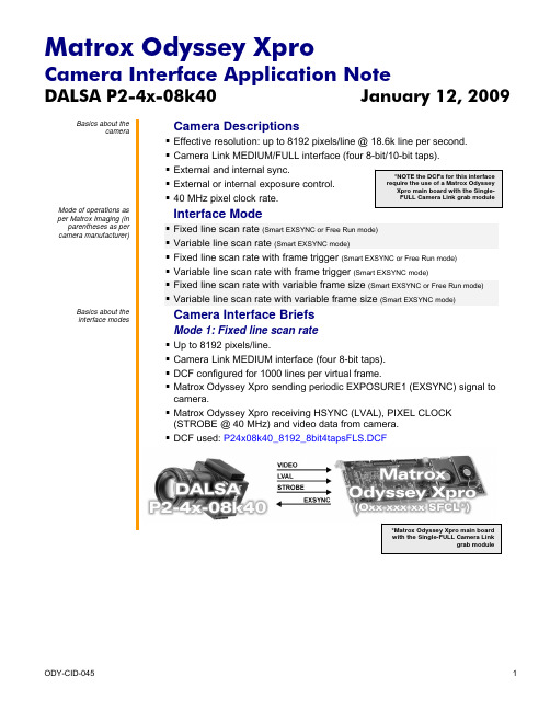
DALSA P2-4x-08k40 January 12, 2009Basics about thecamera Camera Descriptions▪▪ Camera Link MEDIUM/FULL interface (four 8-bit/10-bit taps).▪ External and internal sync.▪ External or internal exposure control. ▪ 40 MHz pixel clock rate. Mode of operations asper Matrox Imaging (in parentheses as percamera manufacturer) Interface Mode ▪ Fixed line scan rate (Smart EXSYNC or Free Run mode)▪ Variable line scan rate (Smart EXSYNC mode)▪ Fixed line scan rate with frame trigger (Smart EXSYNC or Free Run mode)▪ Variable line scan rate with frame trigger (Smart EXSYNC mode) ▪ Fixed line scan rate with variable frame size (Smart EXSYNC or Free Run mode)▪ Variable line scan rate with variable frame size (Smart EXSYNC mode)Basics about theinterface modes Camera Interface BriefsMode 1: Fixed line scan rate▪ Up to 8192 pixels/line.▪ Camera Link MEDIUM interface (four 8-bit taps).▪ DCF configured for 1000 lines per virtual frame.▪ Matrox Odyssey Xpro sending periodic EXPOSURE1 (EXSYNC) signal tocamera.▪ Matrox Odyssey Xpro receiving HSYNC (LVAL), PIXEL CLOCK(STROBE @ 40 MHz) and video data from camera.▪ DCF used: P24x08k40_8192_8bit4tapsFLS.DCFDALSA P2-4x-08k40 January 12, 2009 Basics about theCamera Interface Briefs (continued)interface modesMode 2: Variable line scan rate▪ Up to 8192 pixels/line.▪ Camera Link MEDIUM interface (four 8-bit taps).▪ DCF configured for 1000 lines per virtual frame.▪ Matrox Odyssey Xpro receiving external TTL line trigger signal.▪ Matrox Odyssey Xpro sending EXPOSURE1 (EXSYNC) signal tocamera.▪ Matrox Odyssey Xpro receiving HSYNC (LVAL), PIXEL CLOCK(STROBE @ 40 MHz) and video data from camera.▪ DCF used: P24x08k40_8192_8bit4tapsVLS.DCFMode 3: Fixed line scan rate with frame trigger▪ Up to 8192 pixels/line.▪ Camera Link MEDIUM interface (four 8-bit taps).▪ DCF configured for 1000 lines per virtual frame.▪ Matrox Odyssey Xpro receiving external TTL frame (virtual) trigger signal.▪ Matrox Odyssey Xpro sending periodic EXPOSURE1 (EXSYNC) signal tocamera.▪ Matrox Odyssey Xpro receiving HSYNC (LVAL), PIXEL CLOCK(STROBE @ 40 MHz) and video data from camera.▪ DCF used: P24x08k40_8192_8bit4tapsFLSFT.DCFDALSA P2-4x-08k40 January 12, 2009 Basics about theCamera Interface Briefs (continued)interface modesMode 4: Variable line scan rate with frame trigger▪ Up to 8192 pixels/line.▪ Camera Link MEDIUM interface (four 8-bit taps).▪ DCF configured for 1000 lines per virtual frame.▪ Matrox Odyssey Xpro receiving external TTL frame (virtual) and linetrigger signals.▪ Matrox Odyssey Xpro sending EXPOSURE1 (EXSYNC) signal tocamera.▪ Matrox Odyssey Xpro receiving HSYNC (LVAL), PIXEL CLOCK(STROBE @ 40 MHz) and video data from camera.▪ DCF used: P24x08k40_8192_8bit4tapsVLSFT.DCFMode 5: Fixed line scan rate with variable frame size▪ Up to 8192 pixels/line.▪ Camera Link MEDIUM interface (four 8-bit taps).▪ DCF configured for 1000 lines per virtual frame.▪ Matrox Odyssey Xpro receiving external TTL frame (virtual) trigger signal.▪ Matrox Odyssey Xpro sending periodic EXPOSURE1 (EXSYNC) signal tocamera.▪ Matrox Odyssey Xpro receiving HSYNC (LVAL), PIXEL CLOCK(STROBE @ 40 MHz) and video data from camera.▪ DCF used: P24x08k40_8192_8bit4tapsFLSVF.DCFDALSA P2-4x-08k40 January 12, 2009Basics about theinterface modes Camera Interface Briefs (continued)Mode 6: Variable line scan rate with variable frame size▪ Up to 8192 pixels/line.▪ Camera Link MEDIUM interface (four 8-bit taps).▪ DCF configured for 1000 lines per virtual frame.▪ Matrox Odyssey Xpro receiving external TTL frame (virtual) and linetrigger signals.▪ Matrox Odyssey Xpro sending EXPOSURE1 (EXSYNC) signal tocamera.▪ Matrox Odyssey Xpro receiving HSYNC (LVAL), PIXEL CLOCK(STROBE @ 40 MHz) and video data from camera.▪ DCF used: P24x08k40_8192_8bit4tapsVLSVF.DCFSpecifics about theinterface modes Camera Interface DetailsMode 1: Fixed line scan rate▪ Line rate: The frequency of the periodic EXPOSURE1 (EXSYNC) signal determines the camera’s line rate. The EXPOSURE1 (EXSYNC) signalperiod is set in the DCF to 183 μs which translates into a 2.31 kHz linerate. The maximum line rate for this camera equals 18.6 kHz .▪ Exposure time: For Smart EXSYNC mode the exposure time is theinactive (high level) period between the rising and falling edges of the EXPOSURE1 (EXSYNC) signal. The default exposure time for this DCFequals 130 μs . Maximum/minimum exposure time per line for this DCF is420 ms and 50 ns respectively. The exposure time can be modified in theDCF using Matrox Intellicam, ONL imCamControl() or imDigControl()function, or with the MIL MdigControl() function. Consult the respectivemanual for more information. ▪Inverted tap output: The camera’s tap output configuration featuresmirrored taps of which one tap will need to be inverted. Matrox OdysseyXpro supports hardware tap inversion, which has been enabled in theDCF.DALSA P2-4x-08k40 January 12, 2009 Specifics about theCamera Interface Details (continued)interface modesMode 1: Fixed line scan rate▪Camera communication: This DCF will work with Free Run and SmartEXSYNC modes. Set the mode (as shown in table below) via the CameraLink communication. Refer to the camera manual for additionalinformation.Command Short Form Parameter DescriptionSet_exposure_mode sem 1 or 2 Free RunSet_exposure_mode sem 4 Smart EXSYNC modeMode 2: Variable line scan rate▪Line rate: The line rate is controlled by the frequency of the external TTLline trigger signal. The line trigger signal period must be larger than thetotal duration of the exposure time (high level duration of the timer), theinternal delay of the camera (≈1.50 μs) and the line read out (51.3 μs).▪Exposure time: Refer to Mode 1: Fixed line scan rate.▪Inverted tap output: Refer to Mode 1: Fixed line scan rate.▪Camera communication: Set the mode (as shown in table below) via theCamera Link communication. Refer to the camera manual for additionalinformation.Command Short Form Parameter DescriptionSet_exposure_mode sem 4 Smart EXSYNC mode▪Timing diagram:Mode 3: Fixed line scan rate with frame trigger▪Line/frame rate: The line rate is fixed and controlled by the period ofEXPOSURE1 (EXSYNC) signal. The virtual frame rate is variable andcontrolled by the period of the external frame trigger signal, however theexternal trigger period must always be greater than the total time of thenumber of lines captured. The number of lines per virtual frame(maximum of 1000 for this DCF) is fixed and controlled by the verticaltiming of the DCF. Capture of the lines will start with the rising edge of theframe trigger signal.▪Exposure time: Refer to Mode 1: Fixed line scan rate.Continued…DALSA P2-4x-08k40 January 12, 2009 Specifics about theCamera Interface Details (continued)interface modesMode 3: Fixed line scan rate with frame trigger▪E xposure time: Refer to Mode 1: Fixed line scan rate.▪I nverted tap output: Refer to Mode 1: Fixed line scan rate.▪Camera communication: Refer to Mode 1: Fixed line scan rate.▪Timing diagram:Mode 4: Variable line scan rate with frame trigger▪Line/frame rate: The line rate is controlled by the frequency of theexternal TTL line trigger signal. The line trigger signal period must belarger than the total duration of the exposure time (high level duration ofthe timer), the internal delay of the camera (≈1.50 μs) and the line rate(51.3 μs). The virtual frame rate is variable and controlled by the period ofthe external frame trigger signal, however the external trigger period mustalways be greater than the total time of the number of lines captured. Thenumber of lines per virtual frame (maximum of 1000 for this DCF) is fixedand controlled by the vertical timing of the DCF. Capture of the lines willstart with the rising edge of the frame trigger signal.▪Exposure time: Refer to Mode 1: Fixed line scan rate.▪Inverted tap output: Refer to Mode 1: Fixed line scan rate.▪Camera communication:Refer to Mode 2: Variable line scan rate.▪Timing diagram:DALSA P2-4x-08k40 January 12, 2009 Specifics about theCamera Interface Details (continued)interface modesMode 5: Fixed line scan rate with variable frame size▪Line/frame rate: The line rate is fixed and controlled by the period ofEXPOSURE1 (EXSYNC) signal. The number of lines per virtual frame(maximum of 1000 for this DCF) is variable and controlled by the frametrigger signal. Matrox Odyssey captures lines during the high level of theframe trigger signal. To modify the maximum amount of lines captured,change the active vertical timing period in the DCF. Capture of the lineswill start with the rising edge of the frame trigger signal.▪Exposure time: Refer to Mode 1: Fixed line scan rate.▪Inverted tap output: Refer to Mode 1: Fixed line scan rate.▪Camera communication:Refer to Mode 1: Fixed line scan rate.▪Timing diagram:Mode 6: Variable line scan rate with variable frame size▪Line/frame rate: The line rate is variable and controlled by the externalline trigger frequency. The number of lines per virtual frame (maximum of1000 for this DCF) is variable and controlled by the frame trigger signal.Matrox Odyssey captures lines during the high level of the frame triggersignal. To modify the maximum amount of lines captured, change theactive vertical timing period in the DCF. Capture of the lines will start withthe rising edge of the frame trigger signal.▪Exposure time: Refer to Mode 1: Fixed line scan rate.▪Inverted tap output: Refer to Mode 1: Fixed line scan rate.▪Camera communication:Refer to Mode 2: Variable line scan rate.Continued…DALSA P2-4x-08k40 January 12, 2009 Specifics about theCamera Interface Details (continued)interface modesMode 6: Variable line scan rate with variable frame size▪Timing diagram:Cabling details for theCabling Requirementsinterface modesMode 1: Fixed line scan rate▪Cable and Connection: Standard Camera Link cable.Mode 2: Variable line scan rate▪Cable and Connection: Standard Camera Link.▪External trigger: External line trigger should be connected to the OPTOTRIG input of the 9-pin connector (pins 7 and 2) on the External I/Oadapter bracket:EXTERNAL I/O BRACKET(9-pin connector) External Trigger SourcePin Name Pin no. Pin NameOPTO_AUX_IN0 + 07 ←LINE TRIGGER (TTL FORMAT)OPTO_AUX_IN0 - 02 ←LINE TRIGGER (GROUND)Mode 3: Fixed line scan rate with frame trigger▪Cable and Connection: Standard Camera Link.▪External trigger: External line trigger should be connected to the OPTOTRIG input of the 9-pin connector (pins 4 and 5) on the External I/Oadapter bracket:EXTERNAL I/O BRACKET(9-pin connector) External Trigger SourcePin Name Pin no. Pin NameOPTO_AUX_IN1 + 04 ←FRAME TRIGGER (TTL FORMAT)OPTO_AUX_IN1 - 05 ←FRAME TRIGGER (GROUND)Matrox Odyssey XproCamera Interface Application NoteDALSA P2-4x-08k40 January 12, 2009 Cabling details for theCabling Requirementsinterface modesMode 4: Variable line scan rate with frame trigger▪Cable and Connection: Standard Camera Link.▪External trigger: External frame and line triggers should be connected to theOPTO TRIG inputs of the 9-pin connector on the External I/O adapterbracket:EXTERNAL I/O BRACKET(9-pin connector) External Trigger SourcesPin name Pin no. Pin nameOPTO_AUX_IN1 + 04 ←FRAME TRIGGER (TTL FORMAT)OPTO_AUX_IN1 - 05 ←FRAME TRIGGER (GROUND)OPTO_AUX_IN0 + 07 ←LINE TRIGGER (TTL FORMAT)OPTO_AUX_IN0 - 02 ←LINE TRIGGER (GROUND)Mode 5: Fixed line scan rate with variable frame size▪Cable and Connection: Standard Camera Link.▪External trigger: External trigger should be connected to the OPTO TRIGinput (pins 4 and 5) of the 9-pin connector on the External I/O adapterbracket:EXTERNAL I/O BRACKET(9-pin connector) External Trigger SourcesPin name Pin no. Pin nameOPTO_AUX_IN1 + 04 ←FRAME TRIGGER (TTL FORMAT)OPTO_AUX_IN1 - 05 ←FRAME TRIGGER (GROUND)Mode 6: Variable line scan rate with variable frame size▪Cable and Connection: Standard Camera Link.▪External trigger: External frame and line triggers should be connected to theOPTO TRIG inputs of the 9-pin connector on the External I/O adapterbracket:EXTERNAL I/O BRACKET(9-pin connector) External Trigger SourcesPin name Pin no. Pin nameOPTO_AUX_IN1 + 04 ←FRAME TRIGGER (TTL FORMAT)OPTO_AUX_IN1 - 05 ←FRAME TRIGGER (GROUND)OPTO_AUX_IN0 + 07 ←LINE TRIGGER (TTL FORMAT)OPTO_AUX_IN0 - 02 ←LINE TRIGGER (GROUND)The DCFs mentioned in this application note are also attached (embedded) to this PDF file – use the Adobe Reader’s View File Attachment to access the DCF files. The information furnished by Matrox Electronics System, Ltd. is believed to be accurate and reliable. Please verify all interface connections with camera documentation or manual. Contact your local sales representative or Matrox Sales office or Matrox Imaging Applications at 514-822-6061 for assistance. © Matrox Electronic Systems Ltd, 2009-2011.Matrox Electronic Systems Ltd.1055 St. Regis Blvd.Dorval, Quebec H9P 2T4CanadaTel: (514) 685-2630Fax: (514) 822-6273。
TURBO HD D0T Series Bullet CameraUser ManualUser ManualThank you for purchasing our product. If there are any questions, or requests, do not hesitate to contact the dealer.This manual applies to the models below:ModelDS-2CE16D0T-I2PFBDS-2CE16D0T-I2FBThis manual may contain several technical incorrect places or printing errors, and the content is subject to change without notice. The updates will be added to the new version of this manual. We will readily improve or update the products or procedures described in the manual.0100001090102Regulatory InformationFCC InformationPlease take attention that changes or modification not expressly approved by the party responsible for compliance could void the user’s authority to operate the equipment.FCC compliance: This equipment has been tested and found to comply with the limits for a Class A digital device, pursuant to part 15 of the FCC Rules. These limits are designed to provide reasonable protection against harmful interference when the equipment is operated in a commercial environment. This equipment generates, uses, and can radiate radio frequency energy and, if not installed and used in accordance with the instruction manual, may cause harmful interference to radio communications. Operation of this equipment in a residential area is likely to cause harmful interference in which case the user will be required to correct the interference at his own expense.FCC ConditionsThis device complies with part 15 of the FCC Rules. Operation is subject to the following two conditions:1. This device may not cause harmful interference.2. This device must accept any interference received, including interference that may cause undesired operation.EU Conformity StatementThis product and - if applicable - thesupplied accessories too are marked with"CE" and comply therefore with theapplicable harmonized European standards listed under the Low Voltage Directive2014/35/EU, the EMC Directive 2014/30/EU, the RoHS Directive 2011/65/EU.2012/19/EU (WEEE directive): Productsmarked with this symbol cannot bedisposed of as unsorted municipal waste inthe European Union. For proper recycling,return this product to your local supplierupon the purchase of equivalent new equipment, or dispose of it at designated collection points. For more information see: . 2006/66/EC (battery directive): This product contains abattery that cannot be disposed of asunsorted municipal waste in the EuropeanUnion. See the product documentation forspecific battery information. The battery ismarked with this symbol, which may include lettering to indicate cadmium (Cd), lead (Pb), or mercury (Hg). For proper recycling, return the batteryto your supplier or to a designated collection point. For more information, see: .Industry Canada ICES-003 ComplianceThis device meets the CAN ICES-3 (A)/NMB-3(A) standards requirements.WarningThis is a class A product. In a domestic environment this product may cause radio interference in which case the user may be required to take adequate measures.Safety InstructionThese instructions are intended to ensure that user can use the product correctly to avoid danger or property loss.The precaution measure is divided into “Warnings” and “Cautions”.Warnings: Serious injury or death may occur if any of the warnings are neglected.Cautions: Injury or equipment damage may occur if any of the cautions are neglected. ArrayWarnings●In the use of the device, you must be in strict compliance with the electrical safety regulations of the nation and region.●Input voltage should meet both the SELV (Safety Extra Low Voltage) and the Limited Power Source with 12 VDC according to the IEC60950-1 standard. Refer to technical specifications for detailed information.●Do not connect multiple devices to one power adapter to avoid over-heating or a fire hazard caused by overload.●Make sure that the plug is firmly connected to the power socket.●Make sure that the device is firmly fixed if wall mounting or ceiling mounting is adopted.●If smoke, odor or noise rise from the device, turn off the power at once and unplug the power cord, and then contact the service center.●Never attempt to disassemble the camera by unprofessional personal.Cautions●Do not drop the camera or subject it to physical shock.●Do not touch senor modules with fingers.●Do not place the camera in extremely hot, cold (the operating temperature shall be -40°C to 60°C), dusty or damp locations, and do not expose it to high electromagnetic radiation.●If cleaning is necessary, use clean cloth with a bit of ethanol and wipe it gently.●Do not aim the camera at the sun or extra bright places.●The sensor may be burned out by a laser beam, so when any laser equipment is in using, make sure that the surface of sensor will not be exposed to the laser beam.●Do not expose the device to high electromagnetic radiation or extremely hot, cold, dusty or damp environment.●To avoid heat accumulation, good ventilation isrequired for the operating environment.●Keep the camera away from liquid while in use for non-water-proof device.●While in delivery, the camera shall be packed in its original packing, or packing of the same texture.Mark Description1Introduction1.1Product FeaturesThe main features are as follows:●High performance CMOS sensor●IR cut filter with auto switch●OSD menu with configurable parameters●Auto white balance●SMART IR mode●3-axis adjustment1.2OverviewFigure 1-1Overview of the CameraNote:1)Press and hold the switch button for 5 secondsto switch the video output. Four kinds of videooutputs are available: TVI, AHD, CVI, and CVBS.2)The Auxiliary Video Interface is for theprofessional personnel debugging ormaintenance.2InstallationBefore you start●Make sure that the device in the package is in good condition and all the assembly parts are included.●Make sure that all the related equipment is power-off during the installation.●Check the specification of the products for the installation environment.●Check whether the power supply is matched with your power output to avoid the damage.●Make sure the wall is strong enough to withstand three times the weight of the camera, and the mount.●If the wall is cement, insert expansion bolts before installing the camera. If the wall is wooden, useself-tapping screws to secure the camera.●If the product does not function properly, contact your dealer or the nearest service center. Do NOT disassemble the camera for repair or maintenance by yourself.2.1Installation of the Camera2.1.1Ceiling/Wall MountingSteps:1.Paste the drill template (supplied) to the placewhere you want to install the camera.2.Drill the screw holes on the ceiling/wall according tothe drill template.Figure 2-1The Drill Template3.You have two ways to install the camera accordingto different types of wall/ceiling.1)Install the camera to the wooden ceiling/wallwith three PA4 × 25 screws.Figure 2-2Install the Camera to the Wooden Ceiling2)Install the expansion bolts to the cementceiling at first, then secure the camera withthree PA4 × 25 screws.Figure 2-3Install the Camera to the Cement Ceiling Note:The supplied screw package contains self-tapping screws, and expansion bolts.4.Route the cables through the cable hole, or the sideopening.5.Connect the corresponding power cord, and videocable.6.Power on the camera to check whether the imageon the monitor is gotten from the optimum angle. If not, adjust the camera according to the figure below to get an optimum angle.Pan Position][0° to 360°]Figure 2-43-axis Adjustment1).Loosen the P screw to adjust the pan position [0°to 360°]. Tighten the screw after completing theadjustment.2).Loosen the T screw to adjust the tilt position [0°to 180°]. Tighten the screw after completing theadjustment.3).Loosen the R screw and rotate the camera [0° to360°]. Tighten the screw after completing theadjustment.2.1.2Ceiling/Wall Mounting with Junction BoxBefore you start:You need to purchase a junction box in advance. Steps:1.Paste the drill template (supplied) to the placewhere you want to install the camera.2.Drill screw holes on the ceiling/wall according to thedrill template.Figure 2-5The Drill Template3.Take apart the junction box, and align the screwholes of the camera with those on the Junctionbox’s cover.4.Attach the camera to the junction box’s cover withsupplied screws.Figure 2-6Attach the Camera to the Junction Box’sCover5.Attach the junction box’s body to the ceiling/wall byaligning the screw holes of the junction box.6.Secure the junction box’s body on the ceiling/wallwith supplied screws.Figure 2-7Secure the Junction Box’s Body to theWall/Ceiling7.Route the cables through cable holes, or sideopenings.bine the junction box’s cover with its body.Figure 2-8Combine the Junction Box’s Cover with itsBody9.Repeat the step 5 and 6 of 2.1.1Ceiling/WallMounting to finish the installation.3 Menu DescriptionFollow the steps below to call the menu. Note:The actual display may vary with your camera model. Steps:1. Connect the camera with the TVI DVR, and the monitor, shown as the figure 3-1.Figure 3-1 Connection2. Power on the camera, TVI DVR, and the monitor to view the image on the monitor.3. Click PTZ Control to enter the PTZ Control interface.4. Call the camera menu by clicking button, or call the preset No. 95.Figure 3-2 Main Menu Overview5. Click the direction arrow to control the camera.1). Click up/down direction button to select the item.2). Click Iris + to confirm the selection.3). Click left/right direction button to adjust the value of the selected item.3.1 FORMATYou can set the video format to 1080P@25fps or 1080P@30fps .3.2 LANGUAGEEnglish is available.3.3 MAIN MENUAE (Auto Exposure)You can adjust BRIGHTNESS , EXPOSURE MODE , AGC , DWDR in this section. BRIGHTNESSBrightness refers to the brightness of the image.The higher the value is, and more brighter the image is.●EXPOSURE MODEYou can set the EXPOSURE MODE to GLOBAL, BLC, or HLC.GLOBALGLOBAL refers to the normal exposure mode which adjusts lighting distribution, variations, andnon-standard processing.BLC (Backlight Compensation)The BLC (backlight compensation) function can compensate light to the object in the front to make it clear, but this causes the overexposure of the background where the light is strong.HLC (Highlight Compensation)HLC stands for highlight compensation. The camera detects the strong spots (the over-exposure portion of image), then reduce the brightness of the strong spots to improve the overall images.●AGC (Auto Gain Control)It optimizes the clarity of the image in poor light conditions. The AGC level can be set to HIGH, MIDDLE, or LOW.Note:The noise will be amplified when the AGC is on.●DWDR (Digital Wide Dynamic Range)Digital wide dynamic range gives the camera the ability to view dark areas of the given image as well as extremely lighted portions of the image, or areas of high contrast.WB (White Balance)White balance, the white rendition function of the camera, is to adjust the color temperature according to the environment. It can remove unrealistic color casts in the image. You can set WB mode to AUTO (ATW), or MANUAL (MWB).●AUTOUnder AUTO mode, white balance adjusts automatically according to the color temperature of the scene illumination.●MANUALYou can set the R-GAIN/B-GAIN value to adjust the shades of red/blue color of the image.Figure 3-1WBDAY/NIGHTYou can select the DAY/NIGHT as B/W, SMART, or COLOR.●B/WThe image is black and white all the time.●SMARTSMART refers to Smart IR. The function is used to adjust the light to its most suitable intensity, and prevent the image from overexposure.Figure 3-2DAY/NIGHT●COLORThe image is colorful in day mode all the time.VIDEO SETTINGSMove the cursor to VIDEO SETTINGS and click Iris+ to enter the submenu. IMAGE MODE, CONTRAST, SHARPNESS, COLOR GAIN, DNR, and MIRROR are adjustable.Figure 3-3VIDEO SETTINGS●IMAGE MODEIMAGE MODE is used to adjust the image saturation, and you can set it to STD (Standard), or HIGH-SAT (High Saturation).●CONTRASTThis feature enhances the difference in color and light between parts of an image. You can set the CONTRAST value from 1 to 10.●SHARPNESSSharpness determines the amount of detail an imaging system can reproduce. You can set the SHARPNESS value from 1 to 10.●COLOR GAINCOLOR GAIN is determined by a combination of light intensity and how much it is distributed across the spectrum of different wavelengths.●DNR (Digital Noise Reduction)The DNR function can decrease the noise effect, especially when capturing moving images in poor light conditions, and delivering more accurate and sharper image.●MIRROROFF, H, V, and HV are selectable for mirror.OFF: The mirror function is disabled.H: The image flips 180° horizontally.V: The image flips 180° vertically.HV: The image flips 180° both horizontally and vertically.3.4RESETReset all the settings to the factory default.3.5SAVE & EXITMove the cursor to SAVE & EXIT and click Iris+ to save the settings, and exit the menu.UD12862B。
FD Trinitron Colour TelevisionHow to replace the fuseOpen the fuse compartment with a blade screwdriver, and replace the fuse.If the plug supplied is not suitable for the socket outlets in your home, it should be cut off and an appropriate plug fitted in accordance with the following instructions:The wires in this mains lead are coloured in accordance with the following code:terminal which is marked with the letter L or coloured red. Do not connect either wire to theRecording button: Media Selector:With this remote control you can operate not only this TV but also the main functions of your VCR or DVD.Switch on the device you want to operate and next press this button repeatedly to select the VCR, TV or DVD. A green light will be momentarily lit to indicate the chosen function.Before the first time you want to control a DVD or VCR by using this remote control, you have to set it up depending on the brand of the device to be used. For more details, refer to chapter “Remote Control Configuration for VCR or DVD” on page 20.Selecting channels: Muting the Sound: Adjusting TV volume: Displaying the menu system: remove the menu display from the TV screen.Selecting TV mode: Selecting Sound effect: Selecting Picture mode: Displaying on Screen information: to cancel.VCR or DVD on/off: Overview of Remote Control ButtonsBesides TV functions, all coloured buttons as well as green symbols are also used for Teletext operation. For more details, please refer to “Teletext” section of this instruction manual.12!ª!•!¶!§!∞!¢!£!™4678!º!¡593Inserting Batteries into the Remote Control Make sure you insert the supplied batteries using the correct polarities.Always remember to dispose of used batteries in an environmental friendly way.Connecting the Aerial and VCROverview-InstallationConnecting cables are not supplied.On/Off switch Standby indicator Press on the mark on the door flap to reveal the control panel.orScart lead is optional.For more details of VCR connection, please refer to the section “Connecting Optional Equipment” of this instruction manual.Language 4 Svenska NorskManufactured under license from Dolby Laboratories. “Dolby”, “Pro Logic” and the double-D symbol are trademarks of Dolby Laboratories.Menu SystemTo avoid picture distortion, do not connect external equipment to connectors at the same time.Do not connect a Decoder to the Scart F .Games that use a “gun” attachment to point at the screen do not work correctly due to 100 Hz technology used in this television.Connecting a VCR:To connect a VCR, please refer to the section “Connecting the aerial and VCR” of this instruction manual. We recommend you connect your VCR using a scart lead. If you do not have a scart lead, tune in the VCR test signal to the TV programme number “0” by using the “ManualProgramme Preset” option. (for details of how to manually programme these presets, see page Refer to your VCR instruction manual to find out how to find the output channel of your VCR.Connecting a VCR that supports Smartlink:Smartlink is a direct link between the TV set and the VCR. For more information on Smartlink, please refer to the instruction manual of your VCR.If you use a VCR that supports Smartlink, please connect the VCR to the TV using a Scart lead to the Scart “PlayStation”*DecoderHi-fiDVD* “PlayStation” * “PlayStation 8mm/Hi8/DVCcamcorderS VHS/Hi8DVCcamcorderBECADWhen you connect the headphones, the TV speakers will automaticallybutton repeatedly until theAudio / video input signal through the Scart connector EYour sitting position~50°speakerspeaker213below. On those brands that have more than one code, enter the first code number.Therefore, please refer to the code table included with the remote control for If your selected code is entered correctly, all three green lights will be lit please check that you entered the correct code set or try the next code • Your brand codes may be lost if weak batteries are not replaced within a few minutes. To reset your brand of DVD or VCR please repeat the above steps. A small label is added inside the battery door to allow you • Not all brands are covered and not all models of every brand may be covered.018, 027, 020, 002009, 028, 023, 024, 016, 003025, 026, 015, 004009, 028, 023, 024, 016, 003018, 027, 020, 002009, 028, 023, 024, 016, 003018, 027, 020, 00223 Additional Information。
1100 Lakeside Dr Gurnee , IL60031, United States T oll Free:(866)812-1107Local & International: (847)201-4623Fax: (847) 261-0295Fotodiox Inc.w w w .f o t o d i o x p r o .c o mRRUSER MANUALPZM-700RJ U P I T E R 18Introduction:Thank you for choosing the FACTOR Prizmo lighting series from Fotodiox Pro. This light is designed with an all-aluminum frame, and a good heat dissipation system. It is a compact, soft and highly efficient multicoloured LED light.Not only can you control the color and color temperature of the light, you can also adjust the green and magenta points for optimized spectrum and good color effects. All models can be controlled by using the popular DMX512 protocol or menu controls built on the light. These lights can also be controlled with an available optional remote control or mobile APP .Warnings:1.Do not disassemble or modify the light.2.Remove batteries when in storage.3.Do not operate in environments near flammable gasses or volatile liquids as this may increase the risk of explosion or fire.4.Do not operate in enclosed spaces where heat buildup can be extreme, such as inside a car on a sunny day. The increased heat may cause premature failure of the lighting unit.5.Do not touch or operate with wet hands, doing so may cause electric shock.6.Do not damage, disassemble, twist or modify the power cord as doing so may increase the risk of fire or electric shock.7.Do not place under heavy objects.8.ONLY use the provided AC power adapter. Using other AC power adapters may result in damage to your light.9.Avoid impact to the LCD screen.10.Avoid dust and debris buildup as this will change the illuminance and color temperature. Keep the light surface clean with a soft, dry cloth.11.When hanging the light, always use the included safety cable.12.Do not block the air inlet for the cooling fan. Doing so will inhibit heat dissipation and may cause excess noise.Characteristics:1.All-aluminum frame is lightweight and strong with good heat dissipation to ensure a long product life.4.Fully adjustable brightness from 0-100%.5. Multiple pre-programmed scenes and effects.6. High CRI and TLCI, CRI :93-98, TLCI :95-97.7.Can be powered using an external battery; convenient for location B port designed to update the software.9.LCD screen shows the kinds of data.10.LED low heat technology means that it will emit steady and accurate light under varying patible with DMX512, can be controlled by DMX512 console or remote control.12.Suitable for broadcasting studio, film and television production, location shooting and more.2.Fully adjustable color temperature from 2800K-10000K.plete 0-360° color selection (RGB+WT color spectrum).Light unit -1PCAC power adapter (144W)-1PC Power cord -1PC DMX cable-1PC Safety cable-1PCInstruction manual-1PCBag -1PC[PZM-700R ]1234567PZM-700R Packing List:Optional Accessories:Fabric GridHoneycomb gridRemote control Mobile APP Soft diffuser --1PC8Light emission surface Y okeY oke locking knobV-lock plateV-lock release button Control panelStand mount locking screwControl Panel Diagram:AA GC B PZM-700RA B C D E FG H I JKH G FABJ IC PZM-700R Control Panel Diagram:DEKBC EFD D FE G 000000DMX input T ouch buttons(CCT , HSI, RGBWT , MENU, Filters, Special Effect, Scenes, BACK )USB portPower ON/OFF switchKnob 1 – IntensityKnob 2–SAT ( saturation )Knob 3 – Selector ( with touch button functionality )LCD screenIndicator lights ( 2 indicators )4-pin XLR socketParts Diagram:DMX outputPZM-700R Illuminance:IlluminanceColor temperatureNO .2800K 5100Lux 1470Lux 418Lux 82Lux3200K 5670Lux 1540Lux 440Lux 87Lux5600K 6360Lux 1770Lux 508Lux 99Lux10000K 5830Lux 1670Lux 460Lux 91Lux0.5m 1m 2m 5mRed 1520Lux 440Lux 127Lux 4400Lux 1270Lux 360Lux 770Lux 210Lux 63Lux 0.5m 1m 2m Green Blue 25Lux72Lux12Lux5mDistanceSpecifications:12 3 4 567 8910111213 14151617 1819 95-9793-98Diffusion panel ø407MMFullRGB+W spectrum with hue saturation control adjustment from 0-100% adjustment from 2800K-10000K+/-200KAC100-240V ,50/60Hz,DC15V 100Wmax V-lock plate DC12-17V 0-80% -20-45℃ 50,000hours expected 7.78lbs (3.53Kg)without adapter,9.41lbs (4.27Kg) with adapter510x560x75MMNameDMX512,Remote control,Mobile APP(for future application) 120°IP20Optical system Light emission surface Beamangle Color Intensity/brightness White light CRI TLCI Colortemper atureerror Remote control Power input Power output Battery mount Battery mode power output Working temperature ProtectionLED lifetime Weight Dimensionse the Honeycomb Grid(1) Insert the lower end of the honeycomb grid into the slot of the left and right buckles under the front panel of the light body, and then the top of the honeycomb grid into the left and right buckles above the light body.(2) Check the four buckles after installation to ensure that they are in place.(3) T o remove the honeycomb grid, open the upper two buckles in turn, and pull out the honeycomb grid.Operating Instructions:1.Set-up instructions:(1) T wist the stand mount locking screw counterclockwise to loosen until the stand or stud can be inserted into the socket. T wist the stand mount locking screw clockwise to tighten in place.(2) When mounting to a 1/8” stud, it will be necessary to remove the set screw.4.How to use the safety cable(1) When hanging the product, always use the safety cable.(2) The safety cable is fixed through the yoke and the external fixing frame.Battery power PZM-700RIlluminanceColor temperature Distance20Stand mount locking screw()Plug the adapter's DC output into the 4-pin XLR socket located in the lower left corner of the control panel.(2)Plug in the adapter's AC power cord to connect to external AC power (AC100-240V).5.Connecting the power supply1SAT 0-100%(1) The V-lock holder is already mounted on the adapter when it is shipped from the factory.(2) Install the power adapter with V-lock plate on the back of the light.It is successfully installed when you hear the lock mechanism click..4.How to Install the AC power adapter(3) T o remove the adapter, press down on the V-lock release button and push the adapter out of the V-lock plate.6.Battery PowerInsert your V-lock battery (sold separately) into the V-lock plate. T o remove the battery, press the release button and slide the battery out in the opposite direction.This product can be powered by an external battery attached to the product's built in V-lock plate. Note: The PZM-700R operates on battery with an output power of 150W or more.2.Saturation Knob:3.Intensity knob:Functions of the control knobs: 1.Selector Knob:Rotate the selector knob to select the desired mode in the menu, press once to select.In certain modes, parameters such as CCT , CMB, SPD, and Frq may be adjusted using this knob.In HSI, CCT , RGBWT mode, press the knob for several seconds to save the current settings.Selector KnobIn the HSI mode, SAT can be adjusted from 0-100%. In other modes, parameters such as SAT , CMB, Col, may be adjusted using this knob.Attaching the adapterRemoving the adapterAdjusts brightness from 0-100% in any mode.brightness 0-100%When the device requires a software upgrade, you can connect to the USB flash drive through this port.(Upgrade software can be downloaded from )WELCOME TO USEMENU 1.2.HSI3.RGBWT4.Filters5.Special Effect6.Scenesng8.DMX Settings9.RMT SettingsCCT FOTODIOX USBB port operation:Operations:1.Download the upgrade program to the USB flash drive on 2.Insert the USB flash drive with the upgrade program into the USB port on the back of the light.3.Power on, DATA indicator flashes, LCD backlight is lit until the “Welcome” interface appears.4.The upgrade time is about 15 seconds. After the upgrade is complete, remove the USB flash drive and put on the dustproof plug.1.Battery indicatorWhen the battery indicator light is on: the V-lock battery is being used to power the light. When the battery indicator light flashes: the V-lock battery is running low.When the battery indicator light is off: the AC power adapter is being used to power the light. Note: when the battery is used to power the light, the max output power is reduced to 80%.2.Data indicatorWhen the data indicator is on: the DMX512 remote control function is being used. When the data indicator flashes: the USB port is being used for data upgrade.The data indicator flashes once each time the light receives an effective remote control signal.Operating Instructions:e the Selector knob to highlight the desired sub-menu option, press the knob once to select.2.In the main menu, you can also press the touch buttons to enter a menu option directly, There are nine modes: CCT , HSI, RGBWT , Filters, Special Effects,Scenes, Language, DMX Setting and Remote control.3.From any of the menu option modes, press the BACK button to return to the previous menu. Y ou can also enter the main menu using the MENU button.Main menu(Boot screen welcome message)1.LCD display screen and menu instructions:Indicator function description:BatteryData[Menu function instructions:]Use the selector knob to highlight the desired effect. Push the knob once to enter. Use the selector, saturation and intensity knobs to adjust the parameters.*OFF*Party effect-----SPD (speed): 0-100% SAT: 0-100% INT: 0-100%*Candle-----SPD: 0-100% COL: warm / warm white / white INT: 0-100%*Clouds-----SPD: 0-100% INT: 0-100%*Club lights-----SPD: 0-100% COL: 03-24 INT: 0-100%*Color chase-----SPD: 0-100% SAT: 0-100% INT: 0-100%*Cop car-----COL: R+B+W / B+W / R+B / B INT: 0-100%*Fire-----SPD: 0-100% INT: 0-100%*Fireworks-----FRQ(frequency): 0-100% COL: COLOR / WHITE / C+W INT: 0-100%*Lightning-----SPD: 0-100% INT: 0-100%5.Filters4.Special effects3.RGBWTRGBWT selection ----------------------------------adjust using the “Selector” knob Red: 0-100% ---------------------------------------adjust using the “Intensity” knob Green: 0-100% ------------------------------------adjust using the “Intensity” knob Blue: 0-100% ---------------------------------------adjust using the “Intensity”knob White: 0-100% -------------------------------------adjust using the “Intensity” knob Tungsten: 0-100% ----------------------------------adjust using the “Intensity” knobT (color temperature)M1, M2, M3, M4, M5------------switch data back and forth with the “Select” knob CCT (color temp.): 2800-10000 K -----------------adjust using the"selector" knob GN:-1/+1----------------------------------------adjust using the “saturation” knob INT: 0-100% ---- ----------------------------------adjust using the “intensity” knob 2.HSIR+G+B, R+G, R+B, G+B --------switch back and forth with the “Selector”knob HUE: 0-360゜ ---- ---------------------------------adjust using the “Selector” knob SAT (saturation): 0-100% ------------------------adjust using the “Saturation” knob INT (intensity): 0-100% --------------------------- adjust using the “Intensity” knobDMX single light connection diagram8 Bit10 ChannelsDMX multiple light connection diagram11.DMX connectionWhen operating DMX, connect the DMX cable to the console (the specific wiring is shown in the diagram below), then set the DMX address to match the console address.12.DMX control: First, the menu needs to be switched to the DMX control interface. Note: Seven channels are required for proper DMX control over all parameters.For example:In DMX address setting 1, 1-1 is brightness control, 1-2 is color temperature control, 1-3 is red and green deviation control, 1-4 is saturation control, 1-5 is monochrome red control, 1-6 is monochrome green control, and 1-7 is monochrome blue control.DMX console5126.ScenesUse the selector knob to highlight the desired model. Push the knob once to enter. Use the selector, saturation and intensity knobs to adjust the parameters. *Model ONE [M1 M2 M3 M4 M5]-----(CCT mode) CCT:2800-10000 K INT: 0-100% *Model TWO G+B, R+G+B, R+G, R+B-----(HSI mode) HUE: 0-360゜, SAT: 0-100% INT: 0-100% *Model THREE-----(RGBWT mode) Red: 0-100% Green: 0-100% Blu: 0-100% W:0-100% T: 0-100%7.[Lang] (language)Use the selector knob to highlight the desired language. Push the knob once to select. *English *Chinese8.DMX settingsAdjust the DMX address using the selector knob, push the knob to select the address. DMX Address: 001-5129.RMT settings (remote control settings)Remote control operating instructions:1.On the light, go to menu and enter RMT settings. Set the desired wireless receiving address from 0-511.2.On the remote control, go to menu and enter RMT settings. Set the desired wireless receiving address from 0-511.3.Make sure the wireless receiving address on the light matches the light receiving address on the remote control. The remote control can control multiple lights at the same time.4.The wireless remote control has a working distance of approximately 65 feet (20 meters).Note: After setting the wireless receiving address in the RMT settings on the light, you cannot change the address through the remote control. Y ou can only manually adjust it through the RMT settings on the light.10.Factory resetT o restore the light or remote control to factory settings:Press and hold the MENU button on the light or on the remote control for more than 4 seconds in the main menu on the light, the entire device will reset, and the data will be restored to the factory setting state.All Fotodiox products are backed by a 24 month limited warranty.。