上海林肯电气POWERPLUS_TM_系列焊机的使用与维修
- 格式:pdf
- 大小:549.55 KB
- 文档页数:4

SP-100OPERA TOR'S MANUALFor use with machines having Code Number 9284 and above .Sales and Service through Subsidiaries and Distributors WorldwideWorld's Leader in Welding and Cutting Products Premier Manufacturer of Industrial MotorsIM366-BNovember 1993Safety Depends on YouLincoln arc welding equipment is designed and built wit h safet y in mind. However, your overall safety can be increased by proper instal-lat ion ... and t hought ful operat ion on your part.DO NOT INSTALL OPERATE OR REPAIR THIS EQUIPMENT WITHOUT READ-ING THIS MANUAL AND THE SAFETY PRECAUTIONS CON-TAINED THROUGHOUT.And,most importantly, think before you act and be careful.9284; 9429; 9521; 9522; 9725;9726; 9794; 9795; 10050Thank Youfor selecting a QUALITY product by Lincoln Electric.We want you to take pride in operating this Lincoln Electric C ompany product ••• as much pride as we have in bringing this product to you!Read this Operators Manual completely before attempting to use this equipment. Save this manual and keep it handy for quick reference. Pay particular attention to the safety instructions we have provided for your protection. The level of seriousness to be applied to each is explained below:PRODUCT DESCRIPTIONThe SP-100, Type K462, is a complete semiautomatic constant voltage DC arc welding machine. Included is a solid state controlled, single phase constant voltage transformer/ rectifier power source and a wire feeder for feeding .023 – .030" (0.6 – 0.8 mm) solid steel electrode and .035" (0.9 mm) cored electrode.The SP-100 is ideally suited for individuals having access to 115 volt AC input power, and wanting the ease of use, quality and dependability of both gas metal arc welding or GMAW (also known as MIG welding) and the Innershield®electrode process (self-shielded flux-cored or FC AW). A convenient chart is mounted inside the wire feed section door for setting welding procedures for 24 gauge through 12 gauge (0.6 – 2.5 mm) mild steel (Chart also may be found in this manual). The SP-100 is a rugged and reliable machine that has been designed for dependable ser-vice and long life.RECOMMENDED PROCESSES AND EQUIPMENTThe SP-100 can be used for welding mild steel using the GMAW, single pass, process which requires a supply of shielding gas or it can be used for the self-shielded, Innershield electrode process.The recommended gas and electrode for GMAW is welding grade CO2gas and .025" (0.6 mm) diameter Lincoln L-56 mild-steel welding wire [supplied on 12 1/2 lb (6 kg) spools]. For 14 gauge (2.0 mm) and thin-ner, CO2gas is recommended because it gives equal or better performance than a blended gas at a lower cost. A mixed gas consisting of 75 to 80% Argon and 20 to 25% CO2is recommended for welding on heav-ier gauge [12 gauge (2.5 mm) for example] steel.The recommended electrode for the self-shielded process is .035" (0.9 mm) diameter Lincoln Innershield NR-211-MP on 10 lb (4.5 kg) spools. This electrode can be used for all position welding of 20 gauge through 5/16" (1.0 – 8.0 mm) thick steel [multi-ple passes are required for 1/4" and 5/16" (6.0 and 8.0 mm)].OPTIONAL ACCESSORIES1.K463 CO2G as Regulator and Hose Kit—Includes a preset, nonadjustable pressure and flow regulator for use on C O2cylinders. Also included is a 10 foot (3.0 m) gas hose which con-nects to the rear of the SP-100.2.K499 Ar-Mixed Gas Regulator and Hose Kit—Includes a preset, nonadjustable pressure and flow regulator for use on argon-mixed gas cylin-ders. Also included is a 10 foot (3.0 m) gas hose which connects to the rear of the SP-100.3..035 (0.9 mm) Innershield®Welding Kit —Includes a contact tip, a gasless nozzle and a cable liner to permit the SP-100 gun and cable to use a .035" (0.9 mm) diameter flux-cored elec-trode. Also included is a spool of .035 (0.9 mm) Innershield®NR-211-MP.Two kits are available:K549-1 kit is for use with the Magnum™100L gun (with red trigger).K464 kit is for use with the original Lincoln Electric®gun (with black trigger).4.M15448-1 Reversible Drive Roll with doubleknurled grooves for .035 cored electrode.5.K467 Input Line Cord — Same as line cord sup-plied with the SP-100 but has a NEMA type 5-20P plug for use on 25 amp branch circuits.To install optional features refer to instructions included with the kit, and/or in this manual.INSTALLATIONDESCRIPTION OF CONTROLSBecome familiar with the SP-100 controls and compo-nents before attempting to weld. Refer to illustrations and lettered items below for brief descriptions.A.Wire speed — Controls the wire speed from 50 –400 in./min (1.3 – 10 m/min). The control can be preset on the dial to the setting specified on the SP-100 Application Chart located on the inside of the wire feed section door. Wire speed is not affected when changes are made in the voltage control. The control is marked (“olo”)B.Power ON/OFF switch — When the power is on,the fan motor will run and air will be exhausted out the louvers in the front of the machine. The welding output and wire feeder remain off until the gun trigger is pressed.C.Voltage control — A continuous control that givesfull range adjustment of power source output volt-age. Can be adjusted while welding.D.Thumbscrew — secures gun and cable assembly.E.Positive (+) and negative (–) output terminals.F.Shielding gas hose (factory installed, not shown)— routed from gas solenoid inside rear of machine to gun connector block.G.Gun trigger lead connectors.H.Circuit breaker — Protects machine from damageif maximum output is exceeded. Button will extend out when tripped. (Manual reset.)I.Wire spool spindle.J.Gas solenoid inlet fitting.K.Power cord.L.Spring loaded pressure arm — adjusts pressureof idle roll on wire.M.Wire feed gearbox and gun connector block.N.Wire feed section door — With application chartfor machine setting procedures.O.Gun cable and control lead access hole.P.Work cable access hole.LOCATIONLocate the welder in a dry location where there is free circulation of clean air into the louvers in the back and out the front. A location that minimizes the amount of smoke and dirt drawn into the rear louvers reduces the chance of dirt accumulation that can block air pas-sages and cause overheating.WORK CABLE AND CLAMP INSTALLATIONWork Clamp InstallationAttach the work clamp to the work cable per the fol-lowing:1.Unplug the machine or turn the power switch to the “Off” position.2.Insert the work cable terminal lug with the larger hole through the strain relief hole in the work clamp as shown below.3.Fasten securely with the bolt and nut provided.Work cableWork clampWork Cable Installation1.Open the wire feed section door on the right side ofthe SP-100.2.Pass the end of the work cable that has the termi-nal lug with the smaller hole through the hole (holeD) next to the louvers in the case front.3.Route the cable under and around the back of thewire feed unit.ing wing nut provided, connect the terminal lugto the negative (–) output terminal located above the wire feed unit; item M (make certain that both wing nuts are tight).NOTE: This connection gives the correct electrode polarity for the GMAW process. If using Innershield, see Output Polarity C onnection Section below for negative electrode polarity connection. OUTPUT POLARITY CONNECTIONThe SP-100, as shipped, is connected for positiveelectrode polarity.To connect for negative electrode polarity (required for the Innershield process), connect the short cable attached to the gun connector block to the negative (–) output terminal and the work cable to the positive (+) terminal using the provided wing nuts (make cer-tain that both wing nuts are tight).GUN INSTALLATIONAs shipped from the factory, the SP-100 gun is ready to feed .023, .024 or .025" (0.6 mm) wire. If .030" (0.8 mm) wire is to be used, install the .030" (0.8 mm) con-tact tip. .023 – .025" contact tip is stenciled .025 and/or 0.6 mm and .030" contact tip is stenciled .030 and/or 0.8 mm. See Maintenance Section for instruc-tions to change contact tip.If .035" (0.9 mm) Innershield flux cored wire is to be used, see Maintenance Section for instructions to change contact tip, cable liner, and gas nozzle.C onnect the gun cable to the SP-100 per the follow-ing:1.Unplug the machine or turn power switch to the off“O” position.2.Pass the insulated terminals of the gun trigger con-trol leads, one at a time, through the rectangular “keyhole” opening (item F) in the case front. The leads are to be routed under the wire feed unit and through the cable hanger on the inner panel.3.Insert the connector on the gun conductor cablethrough the large hole in the SP-100 case front.Make sure the connector is all the way in the metal connector block to obtain proper gas flow. Rotate the connector so control leads are on the underside and tighten the thumbscrew in the connector block.4.Connect the insulated control lead terminals to thetwo insulated 1/4" (6.4 mm) tab connector bushings located above the “Gun Trigger C onnection” decal in the wire feed section. Either lead can go to either connector. Form the leads so that they are as close as possible to the inside panel.WIRE FEED DRIVE ROLLThe SP-100 drive roll has two grooves; one for .023 –.025" (0.6 mm) solid steel electrode and the other for .030" (0.8 mm) solid and .035" (0.9 mm) flux-cored steel electrode. As shipped, the drive roll is installed in the .023/.025" (0.6 mm) position (as indicated by the stenciling on the exposed side of the drive roll).Replace the washer and retaining screw.connectors{Brass connectorIdle roll armRetaining ScrewWELDING WIRE LOADINGThe machine power switch should be turned to the OFF (“O”) position before working inside the wirefeed enclosure.------------------------------------------------------------------------The machine is shipped from the factory ready to feed 8" (200 mm) diameter spools [2.2" (56 mm) max. width]. These spools fit on a 2" (50 mm) diameter spindle that has a built-in, adjustable* friction brake to prevent overrun of the spool and excess slack in theWARNINGK499 Argon-Mixed Gas Regulator and Hose Kit Install the pressure-flow regulator and gauge to a cylinder according to the instructions in Section 1.10.C onnect one end of the 10 foot (3.0 m) hose to the SP-100 gas inlet fitting and the other end to the regu-lator fitting.The K499 argon-mixed gas pressure-flow regulator is preset by the manufacturer to deliver a nominal flow of 30 cubic feet per hour (14 1/min) of argon or argon-mixed gas. This setting cannot be changed..035" (0.9 mm) Innershield Welding KitIncludes a contact tip, gasless nozzle, and a cable liner to permit the SP-100 gun and cable to use .035 (0.9 mm) diameter flux-cored electrode. Also included is a spool of .035 (0.9 mm) Innershield®NR-211-MP. The K549-1 Kit is for use with the Magnum™100L gun (with red trigger). The fitting on the end of the liner is stenciled with the maximum rated wire size (.045"/1.2 mm).The K464 Kit is for use with the earlier “Lincoln Electric®” gun (with black trigger). The end of the brass fitting on the end of the liner for .035 (0.9 mm) wire is color coded green. The .023-.030 (0.6-0.8 mm) factory installed liner is color coded orange.See Maintenance and Troubleshooting Section for instructions on installing liner and contact tip in gun.K467 Input Line CordSame as line cord supplied with the SP-100 but has a NEMA type 5-20P plug for use on a 25 amp branch circuit with a nominal voltage rating of 115 volts to 125 volts, 60 hertz. Install per the following:1.Turn the SP-100 Power Switch to OFF (“O”).2.If connected, remove the line cord plug from powersupply receptacle.3.Remove the two screws that hold the line cordreceptacle in the SP-100 flanged inlet connector and disconnect the line cord from the SP-100.4.C onnect the S18410 input line cord receptacle tothe SP-100 and replace the retaining screws.OPERATING INSTRUCTIONS1.Decrease stickout2.Increase WFS (wire feed speed) (“oIo”)3.Decrease voltage (“V”)4.Increase speed5.Decrease drag angle6.Check for correct gas, if usedIf Arc Blow Occurs (in order of importance) (NOTE: Try different ground connection locations before adjusting procedures)1.Decrease drag angle2.Increase stickout3.Decrease voltage (“V”)4.Decrease WFS (wire feed speed) (“oIo”) andvoltage (“V”)5.Decrease travel speedTo Eliminate Stubbing (in order of importance)1.Increase voltage (“V”)2.Decrease WFS (wire feed speed) (“oIo”)3.Decrease stickout4.Increase drag angleStubbing occurs when the electrode drives through the molten puddle and hits the bottom plate tending to push the gun up.PROPER GUN HANDLINGMost feeding problems are caused by improper han-dling of the gun cable or electrodes.1.Do not kink or pull the gun cable around sharp cor-ners.2.Keep the gun cable straight as practical when weld-ing.3.Do not allow dolly wheels or trucks to run over thecables.4.Keep the cable clean per maintenance instructionsin this Operation Manual.5.Innershield electrode has proper surface lubrica-tion. Use only clean, rust-free electrode.6.Replace the contact tip when it becomes worn orthe end is fused or deformed.Low or no gas flow Cylinder valve closed Open cylinder valveGas flow not set correctly Set proper flow rateCylinder out of gas Get new cylinder of gasLeak in gas line Inspect and replaceClog or Leak in gun Check for obstruction or defective sealsArc unstable Wrong welding polarity Check polarity - Refer to proper sectionErratic or Intermittent Wrong size, worn and/or Replace tip - remove any spatter on end of tip Arc - Poor Starting melted contact tip"Hunting" ArcWorn work cable or poor connections Inspect - repair or replace as necessaryLoose electrode connections Be sure electrode lead is tight, gun cable tight inwire feeder contact block, gun nozzle and guntip tightM 16576S P 100 W I R I N G D I A G R A MNow Available...12th Edition The Procedure Handbook of Arc WeldingWith over 500,000 copies of previous editions publishedsince 1933, the Procedure Handbook is considered by many tobe the “Bible” of the arc welding industry.This printing will go fast so don’t delay. Place yourorder now using the coupon below.The hardbound book contains over 750 pages of weldinginformation, techniques and procedures. Much of this materialhas never been included in any other book.A must for all welders, supervisors, engineers anddesigners. Many welding instructors will want to use the bookas a reference for all students by taking advantage of the lowquantity discount prices which include shipping by4th class parcel post.$15.00postage paid U.S.A. Mainland How To Read Shop Drawings The book contains the latest information and application data on the American Welding Society Standard Welding Symbols. Detailed discussion tells how engineers and draftsmen use the “short-cut” language of symbols to pass on assembly and welding information to shop personnel.Practical exercises and examples develop the reader’s abilityto visualize mechanically drawn objects as they will appearin their assembled form.187 pages with more than 100 illustrations. Size 8-1/2” x 11”Durable, cloth-covered board binding.$4.50postage paid U.S.A. Mainland New Lessons in Arc Welding Lessons, simply written, cover manipulatory techniques;machine and electrode characteristics; related subjects,such as distortion; and supplemental information on arc welding applications, speeds and costs. Practice materials,exercises, questions and answers are suggested for each lesson.528 pages, well illustrated, 6” x 9” size, bound in simulated,gold embossed leather.$5.00postage paid U.S.A. Mainland Need Welding Training?The Lincoln Electric Company operates the oldest andmost respected Arc Welding School in the United States at itscorporate headquarters in Cleveland, Ohio. Over 100,000stu-dents have graduated. Tuition is low and the training is“hands on”For details write: Lincoln Welding School 22801 St. Clair Ave.Cleveland, Ohio 44117-1199.and ask for bulletin ED-80 or call 216-383-2259 and ask for the Welding School Registrar.Lincoln Welding School BASIC COURSE$700.005 weeks of fundamentals There is a 10%discount on all orders of $50.00 or more for shipment at one time to one location.Orders of $50 or less before discount or orders outside of North America must be prepaid with charge, check or money order in U.S. Funds Only.Prices include shipment by 4th Class Book Rate for U.S.A. Mainland Only.Please allow up to 4 weeks for delivery.UPS Shipping for North America Only.All prepaid orders that request UPS shipment please add:$5.00For order value up to $49.99$10.00For order value between $50.00 & $99.99$15.00For order value between $100.00 & $149.00For North America invoiced orders over $50.00 & credit card orders, if UPS is requested, it will be invoiced or charged to you at cost.Outside U.S.A. Mainland order must be prepaid in U.S. Funds. Please add $2.00 per book for surface mail or $15.00 per book for air parcel post shipment.METHOD OF PAYMENT:(Sorry, No C.O.D. Orders)CHECK ONE:Name:_______________________________________________Please Invoice (only if order is over $50.00)Address:_______________________________________________Check or Money Order Enclosed, U.S. Funds only_______________________________________________Credit Card - Telephone:_______________________________________________Signature as it appears on Charge Card:Account No.Exp Date |_|_||_|_|______________________Month Year USE THIS FORM TO ORDER:Order from:BOOK DIVISION, The Lincoln Electric Company, 22801 St. Clair Avenue, Cleveland, Ohio 44117-1199BOOKS OR FREE INFORMATIVE CATALOGSTelephone: 216-383-2211 or, for fastest service, FAX this completed form to: 216-361-5901.Lincoln Welding School Titles:Price Code Quantity Cost (ED-80)New Lessons in Arc Welding $5.00L Seminar Information Procedure Handbook “Twelfth Edition”$15.00PH (ED-45)How to Read Shop Drawings $4.50H Educational Video Information Incentive Management $5.00IM (ED-93)A New Approach to Industrial Economics $5.00NA James F. Lincoln Arc WeldingThe American Century of John C. Lincoln $5.00AC Foundation Book Information Welding Preheat Calculator $3.00WC-8(JFLF-515)Pipe Welding Charts $4.50ED-89SUB TOTALAdditional Shipping Costs if anyTOTAL COSTJapaneseChineseKoreanArabicREAD AND UNDERSTAND THE MANUFACTURER’S INSTRUCTION FOR THIS EQUIPMENT AND THE CONSUMABLES TO BE USED AND FOLLOW YOUR EMPLOYER’S SAFETY PRACTICES.SE RECOMIENDA LEER Y ENTENDER LAS INSTRUCCIONES DEL FABRICANTE PARA EL USO DE ESTE EQUIPO Y LOS CONSUMIBLES QUE VA A UTILIZAR, SIGA LAS MEDIDAS DE SEGURIDAD DE SU SUPERVISOR.LISEZ ET COMPRENEZ LES INSTRUCTIONS DU FABRICANT EN CE QUI REGARDE CET EQUIPMENT ET LES PRODUITS A ETRE EMPLOYES ET SUIVEZ LES PROCEDURES DE SECURITE DE VOTRE EMPLOYEUR.LESEN SIE UND BEFOLGEN SIE DIE BETRIEBSANLEITUNG DER ANLAGE UND DEN ELEKTRODENEINSATZ DES HER-STELLERS. DIE UNFALLVERHÜTUNGSVORSCHRIFTEN DES ARBEITGEBERS SIND EBENFALLS ZU BEACHTEN.JapaneseChineseKoreanArabicLEIA E COMPREENDA AS INSTRUÇÕES DO FABRICANTE PARA ESTE EQUIPAMENTO E AS PARTES DE USO, E SIGA AS PRÁTICAS DE SEGURANÇA DO EMPREGADOR.(such as loss of business, etc.) caused by the defect or Sales and Service through Subsidiaries and Distributors Worldwide22801 St. Clair Ave. Cleveland, Ohio 44117-1199 U.S.A. Tel. (216) 481-8100Premier Manufacturer of Industrial Motorsd。


MOBIFLEX ®400-MS(/HE) Mobile Filter Unit& LFA 3.1/4.1 Extraction ArmIM10121December, 2011Safety Depends on YouLincoln arc welding and cutting equipment is designed and built with safety in mind. However,your overall safety can be increased by proper installation ... and thoughtful operation on your part.DO NOT INSTALL,OPERATE OR REPAIR THIS EQUIPMENT WITHOUT READ-ING THIS MANUAL AND THE SAFETY PRECAUTIONS CON-TAINED THROUGHOUT.And,most importantly, think before you act and be careful.For use with machines having Code Numbers:K1741-1, K1741-2K2633-1, K2633-2, K2633-3, K2633-4Copyright © Lincoln Global Inc.SECTION A:WARNINGSC ALIFORNIA PROPOSITION 65 WARNINGSWARNING: This product, when used for welding or cutting, produces fumes or gases which contain chemicals known to the State of California to cause birth defects and, in some cases, cancer. (California Health & Safety Code § 25249.5 et seq.)ARC WELDING CAN BE HAZARDOUS. PROTECTYOURSELF AND OTHERS FROM POSSIBLE SERIOUS INJURY OR DEATH. KEEP CHILDREN AWAY.PACEMAKER WEARERS SHOULD CONSULT WITH THEIR DOCTOR BEFORE OPERATING.Read and understand the following safety highlights. For additional safety information, it is strongly recommended that you purchase a copy of “Safety in Welding & Cutting - ANSI Standard Z49.1” from the American Welding Society, P.O. Box 351040, Miami, Florida 33135 or CSA Standard W117.2-1974. A Free copy of “Arc Welding Safety” booklet E205 is available from the Lincoln Electric Company, 22801 St. Clair Avenue, Cleveland, Ohio 44117-1199.BE SURE THAT ALL INSTALLATION, OPERATION,MAINTENANCE AND REPAIR PROCEDURES ARE PERFORMED ONLY BY QUALIFIED INDIVIDUALS.FOR ENGINE POWERED EQUIPMENT.1.a.Turn the engine off before troubleshootingand maintenance work unless themaintenance work requires it to be running.1.b.Operate engines in open, well-ventilated areas or vent the engineexhaust fumes outdoors. 1.c.Do not add the fuel near an open flame weldingwith hot engine parts and igniting. Do not spill fuel when filling tank. If fuel is spilled, wipe it up and do not start engine until fumes have been eliminated.1.d. Keep all equipment safety guards, coversand devices in position and in good repair.Keep hands, hair, clothing and tools away from V-belts, gears, fans and all other moving parts when starting, operating or repairing equipment.1.e.In some cases it may be necessary to remove safety guards toperform required maintenance. Remove guards only when necessary and replace them when the maintenance requiring their removal is complete. Always use the greatest care when working near moving parts. 1.f. Do not put your hands near the engine fan. Do not attempt tooverride the governor or idler by pushing on the throttle control rods while the engine is running. 1.g.To prevent accidentally starting gasoline engines while turningthe engine or welding generator during maintenance work,disconnect the spark plug wires, distributor cap or magneto wire as appropriate. 1.h.To avoid scalding, do not remove the radiatorpressure cap when the engine is hot.ELECTRIC ANDMAGNETIC FIELDS MAY BE DANGEROUS2.a.Electric current flowing through any conductorcauses localized Electric and Magnetic Fields (EMF).Welding current creates EMF fields around welding cables and welding machines 2.b.EMF fields may interfere with some pacemakers, andwelders having a pacemaker should consult their physician before welding. 2.c.Exposure to EMF fields in welding may have other health effectswhich are now not known. 2.d.All welders should use the following procedures in order tominimize exposure to EMF fields from the welding circuit:2.d.1.Route the electrode and work cables together - Securethem with tape when possible.2.d.2.Never coil the electrode lead around your body.2.d.3.Do not place your body between the electrode and workcables. If the electrode cable is on your right side, the work cable should also be on your right side.2.d.4.Connect the work cable to the workpiece as close as pos-sible to the area being welded.2.d.5.Do not work next to welding power source.SAFETYTECHNICAL SPECIFICATIONS - Mobiflex 400-MS(/HE) Base Unit (K1741-1, K1741-2)TECHNICAL SPECIFICATIONS - LFA 3.1 / 4.1 Extraction UnitFIGURE A.1FIGURE A.2FIGURE A.3The Mobiflex 400-MS is a portable unit suitable to be used in relatively small facilities or near sources of pol-lution without a fixed location.The Mobifle 400-MS Base Unit with Fle ible Extraction Arm is used for extracting and filtering fume which is released during the most common welding processes, such as:• MIG/MAG solid wire (GMAW)• MIG/MAG flux cored wire (FCAW)• TIG (GTAW) welding• Stick welding (MMA or SMAW)• Autogeneous weldingThe Mobiflex 400-MS is designed for intermittent or continuous welding applications as indicated above.The Mobiflex 400-MS filter is recommended for annual consumable use of approximately:• 6,000 lbs (2,750 kg) GMAW or FCAW or GTAW• 4,000 lbs (1,800 kg) MMA or SMAW or autoge-neousVariables such as coatings (e.g. oil), base material, weld process, humidity and procedures can affect filter life and performance.MOBIFLEX 400-MS/HE BASE UNITThe K1741-2 Mobiflex 400-MS/HE Base Unit is a mobile filter unit with integrated fan that provides extraction and filtration for use with a flexible extraction arm or optional hose.The Mobiflex 400-MS/HE Base Unit features a steel mesh prefilter and a high efficiency round cellulose/polyester blend LongLife filter cartridge.The Mobiflex 400-MS/HE Base Unit is provided with a RotaPulse system for automatic cleaning of the LongLife filter cartridge.The Mobiflex 400-MS/HE is a portable unit suitable to be used in relatively small facilities or near sources of pollution without a fixed location.The Mobiflex 400-MS/HE Base Unit with Flex ible Extraction Arm is used for extracting and filtering fume which is released during the most common welding processes, such as:• MIG/MAG solid wire (GMAW)• MIG/MAG flux cored wire (FCAW)• TIG (GTAW) welding• Stick welding (MMA or SMAW)• Autogeneous weldingGENERAL DESCRIPTIONThis instruction manual describes two base units and four types of extraction arms & one hose:- K1741-1 Mobiflex 400-MS Base Unit (mobile filter unit with self-cleaning filter cartridge - filter class MERV 11 (untreated); MERV 15 (treated)- K1741-2 Mobiflex 400-MS/HE Base Unit (mobile filter unit with high efficiency self-cleaning filter cartridge -filter class MERV 16)- K2633-1 LFA 3.1 Mobile Manual (10 ft. ex traction arm)- K2633-3 LFA 4.1 Mobile Manual (13 ft. ex traction arm)- K2633-2 LFA 3.1 Mobile Automatic (10 ft. extraction arm with integrated Lamp & Arc Sensor Kit)- K2633-4 LFA 4.1 Mobile Automatic (13 ft. extraction arm with integrated Lamp & Arc Sensor Kit)- K1668-3 Hose & Hood SetMOBIFLEX 400-MS BASE UNITThe K1741-1 Mobiflex 400-MS Base Unit is a mobile filter unit with integrated fan that provides ex traction and filtration for use with a flex ible ex traction arm or optional hose.The Mobiflex 400-MS Base Unit features a steel mesh prefilter and a round cellulose LongLife filter cartridge. This LongLife filter cartridge is provided with a precoat (ExtraCoat) to extend the lifespan and increase initial operating efficiency of the filter.The Mobiflex 400-MS Base Unit is provided with a RotaPulse system for automatic cleaning of the LongLife filter cartridge.The Mobiflex 400-MS is a portable unit suitable to be used in relatively small facilities or near sources of pol-lution without a fixed location.The Mobifle 400-MS Base Unit with Fle ible Extraction Arm is used for extracting and filtering fume which is released during the most common welding processes, such as:• MIG/MAG solid wire (GMAW)• MIG/MAG flux cored wire (FCAW)• TIG (GTAW) welding• Stick welding (MMA or SMAW)• Autogeneous weldingThe Mobiflex 400-MS is designed for intermittent or continuous welding applications as indicated above.The Mobiflex 400-MS filter is recommended for annual consumable use of approximately:• 6,000 lbs (2,750 kg) GMAW or FCAW or GTAW• 4,000 lbs (1,800 kg) MMA or SMAW or autoge-neousVariables such as coatings (e.g. oil), base material, weld process, humidity and procedures can affect filter life and performance.MOBIFLEX 400-MS/HE BASE UNITThe K1741-2 Mobiflex 400-MS/HE Base Unit is a mobile filter unit with integrated fan that provides extraction and filtration for use with a flexible extraction arm or optional hose.The Mobiflex 400-MS/HE Base Unit features a steel mesh prefilter and a high efficiency round cellulose/polyester blend LongLife filter cartridge.The Mobiflex 400-MS/HE Base Unit is provided with a RotaPulse system for automatic cleaning of the LongLife filter cartridge.The Mobiflex 400-MS/HE is a portable unit suitable to be used in relatively small facilities or near sources of pollution without a fixed location.The Mobiflex 400-MS/HE Base Unit with Flex ible Extraction Arm is used for extracting and filtering fume which is released during the most common welding processes, such as:• MIG/MAG solid wire (GMAW)• MIG/MAG flux cored wire (FCAW)• TIG (GTAW) welding• Stick welding (MMA or SMAW)• Autogeneous weldingThe Mobiflex 400-MS/HE is designed for intermittent or continuous welding applications as indicated above.The Mobiflex 400-MS/HE filter is recommended for annual consumable use of approximately:• 550 lbs (250 kg) GMAW or FCAW or GTAW• 385 lbs (175 kg) MMA or SMAW or autogeneousVariables such as coatings (e.g. oil), base material, weld process, humidity and procedures can affect filter life and performance.See Figure B.2 and Figure B.4• Press the power switch ON (See Figure B.2 item B) to turn power to the unit.• Using the handle (See Figure B.4 item A), position the hood of the extraction arm in the desired position at approx imately 6-12 inch (15-30 cm) from the source of fume.• If desired: turn on the halogen lamp using on/off switch (See Figure B.4 item C).• Open the throttle valve (See Figure B.4 item B).• Start welding.Due to the built-in Arc Sensor, the machine will start automatically. After finishing welding, the machine will automatically stop after approximately 20 seconds.• Press the power switch OFF (See Figure B.2 item A) to interrupt power supply.MOBIFLEX 400-MS(/HE) & LFA 3.1/4.1 MOBILE AUTOMATIC (MANUAL START) Manual start of the Lamp & Arc Sensor Kit is recom-mended for TIG welding or in case the Arc Sensor is unable to detect the arc due to weld position.* UV from TIG welding is less than other weld process-es resulting in arc sensor perhaps not detecting weld. See Figure B.2 and Figure B.4• Press the power switch ON (See Figure B.2 item B) to turn power to the unit on.• Using the handle (See Figure B.4 item A), position the hood of the extraction arm in the desired position at approx imately 6-12 inch (15-30 cm) from the source of fume.• If desired: turn on the halogen lamp using on/off switch (See Figure B.4 item C).• Open the throttle valve (See Figure B.4 item B).• Turn on the machine using the on/off switch (See Figure B.4 item D).• Start welding.• Turn off the machine approximately 20 seconds after finishing welding using the on/off switch (See Figure B.4 item D).• Press the power switch OFF (See Figure B.2 item A)to interrupt power supply.OPTIONSK1668-3 HOSE AND HOOD SET (OPTION)The Mobiflex 400-MS(HE) Base Unit can be equipped with a Hose and Hood Set instead of a flexible extrac-tion arm.TABLE D.1 –PERIODIC MAINTENANCE MOBIFLEX 400-MS(/HE) BASE UNITTABLE D.2 –PERIODIC MAINTENANCE LFA 3.1/4.1 MOBILE/AUTOMATICThis Troubleshooting Guide is provided to help you locate and repair possible machine malfunctions.Simply follow the three-step procedure listed below.Step 1.LOCATE PROBLEM (SYMPTOM).Look under the column labeled “PROBLEM (S Y MP-TOMS)”. This column describes possible symptoms that the machine may exhibit. Find the listing that best describes the symptom that the machine is exhibiting. Step 2.POSSIBLE CAUSE.The second column labeled “POSSIBLE CAUSE” liststhe obvious external possibilities that may contribute to the machine symptom.Step 3.RECOMMENDED COURSE OF ACTIONThis column provides a course of action for the Possible Cause, generally it states to contact your local Lincoln Authorized Field Service Facility.Service and Technical SupportFor information about specific adjustments, mainte-nance or repair jobs which are not dealt with in this manual, please contact Lincoln Electric Automation Service 888-935-3878.Make sure you have the following data on hand:- product name - serial number- purchase order (number + date) for warranty verifica-tionHOW TO USE TROUBLESHOOTING GUIDEService and Repair should only be performed by Lincoln Electric Factory Trained Personnel.Unauthorized repairs performed on this equipment may result in danger to the technician and machine operator and will invalidate your factory warranty. For your safety and to avoid Electrical Shock, please observe all safety notes and precautions detailed throughout this manual.__________________________________________________________________________JapaneseChineseKoreanArabicLEIA E COMPREENDA AS INSTRUÇÕES DO FABRICANTE PARA ESTE EQUIPAMENTO E AS PARTES DE USO, E SIGA AS PRÁTICAS DE SEGURANÇA DO EMPREGADOR.JapaneseChineseKoreanArabicREAD AND UNDERSTAND THE MANUFACTURER’S INSTRUCTION FOR THIS EQUIPMENT AND THE CONSUMABLES TO BE USED AND FOLLOW YOUR EMPLOYER’S SAFETY PRACTICES.SE RECOMIENDA LEER Y ENTENDER LAS INSTRUCCIONES DEL FABRICANTE PARA EL USO DE ESTE EQUIPO Y LOS CONSUMIBLES QUE VA A UTILIZAR, SIGA LAS MEDIDAS DE SEGURIDAD DE SU SUPERVISOR.LISEZ ET COMPRENEZ LES INSTRUCTIONS DU FABRICANT EN CE QUI REGARDE CET EQUIPMENT ET LES PRODUITS A ETRE EMPLOYES ET SUIVEZ LES PROCEDURES DE SECURITE DE VOTRE EMPLOYEUR.LESEN SIE UND BEFOLGEN SIE DIE BETRIEBSANLEITUNG DER ANLAGE UND DEN ELEKTRODENEINSATZ DES HER-STELLERS. DIE UNFALLVERHÜTUNGSVORSCHRIFTEN DES ARBEITGEBERS SIND EBENFALLS ZU BEACHTEN.。

MAGNUM® PRO ROBOTIC GUNS DESIGNED FOR LONG LIFE.Thru-ArmExternal DressPublication E12.03 | Issue Date 07/24/20• Patented HexConnect ™ Gun Bushing- Delivers superior mechanical and electrical connectionresulting in longer expendable life. - Resists twisting and provides more points of contactfor current flow.• Fixed Electrical Connection- Robust design resists fatigue - Lasted over 1 milliontortuous flex cycles in extreme lab testing. - Competitive rotating designs can cause micro-arcingresulting in arc instability and potential shorter gun life.Tough Teflon ® Insulation• Single Tool Center Point (TCP) - No need to re-programwhen switching between the Magnum ® PRO 350 and 550 amp expendables.• Contact Tip Technology - Copper Plus ™ - more copper for better heat dissipation.- Anti-Seize ™ thread design on contact tips and diffuser.• Aluminum- Aircraft grade aluminum outer tube extends service.• Copper- High quality copper inner tube enhances electrical conductivity.Contact Tip for up to 550 AMagnum ®PRO 550 A ExpendablesGun Tube Insulator 550 A(1) 550 only350 A and 550 A Magnum ® PRO Expendable Parts are interchangeable. Interchanging will require gun tube insulator and gas diffuser changes. Customersmay choose to change expendable parts to standardize stocking parts or to make the gun more compact for tight spaces.(2)(2)Gas Diffuser for up to 550 A Slip-onGas Diffuser for up to 550 AThread-on (2) Jump liners and wire guides are only used on Thru-arm torches with wire brake.Gas Nozzlefor 550Thread-on 1/8 in. (3.2 mm) RecessedBottleneck Gas Nozzle for 550Thread-on 1/8 in. (3.2 mm)RecessedGENERAL OPTIONSRobotic Gun Tube Straightener Used in the event of a robot crash to check and correct robotic gun tube alignment. OrderK3193-1(Compatible with all standard KP3056-XX and KP3057-XX gun tubes)K3193-2(Compatible with all standard KP3354-XX and KP3355-XX gun tubes)EXTERNAL DRESS OPTIONS External Dress Torch Mounting KitsDesigned to mount the External Dress torch in the proper orientation for the application and fixturing presented to the robot. Consult Automation Division for correct mounting kit selection assistance. OrderKP2769-2222 Degree – Lincoln Electric Tool Center Point (TCP)KP2769-4545 Degree – Lincoln Electric Tool Center Point (TCP)KP2769-180180 Degree – Lincoln Electric Tool Center Point (TCP)KP3054-2222 Degree – Tregaskiss ® TCP, FANUC ® Solid Mount KP3055-2222 Degree – Tregaskiss ® TCP, Tregaskiss ® Clutch Mount KP3499-2222 Degree - Lincoln Electric Tool Center Point (TCP)for ABB and KUKA Robot Arms KP3499-4545 Degree - Lincoln Electric Tool Center Point (TCP)for ABB and KUKA Robot Arms KP3499-180180 Degree - Lincoln Electric Tool Center Point (TCP)for ABB and KUKA Robot ArmsExternal Dress Break-Away Disks Replaceable mounting interface disk designed to protect the robot arm by absorbing the effects of any damage in the event of a robot work envelope collision. OrderKP3194-1External Dress Break-Away Disk (Fanuc iB)KP3194-2External Dress Break-Away Disk (Fanuc 50 iC)KP3194-3External Dress Break-Away Disk (Fanuc iC)KP3194-4External Dress Break-Away Disk(ABB2600)KP3194-5External Dress Break-Away Disk(KR6, KR8, KR10)THRU-ARM OPTIONSThru-Arm Break-Away Disks Replaceable mounting interface disk designed to protect the robot arm by absorbing the effects of any damage in the event of a robot work envelope collision.See specification chart below for correct part number rWire Brake PlugPlug when removing wire brake from K4307-2 Order K3563-1Nose Cone Assemblies See specification chart below for correct part numberTorch HousingsSee specification chart below for correct part numberAir Blast KitBlows spatter from the nozzle orifice. Includes 20 ft (6.1 m) hose and fitting. Order K3352-1Thru-Arm Replacement Cable AssembliesSee specification chart below for correct part numberK466-10(1) K1500-3 Gun Receiver Bushing is required for Power Feed 10 series, LF series and LN-25 PRO wire feeders.(2)Terms are tradmarks of Illinois Tool Works.[3]Included with External Dress Torch [4]Included with Thru-Arm Torch(3)(3) Note that external dress guns include a 22 degree Lincoln Electric TCP gooseneck,liner and consumables. Mounting kit is not included.®®®®®®The Lincoln Electric Company22801 St. Clair Avenue • Cleveland, OH • 44117-1199 • U.S.A.C USTO ME R ASSI STA NC E PO LICYThe business of The Lincoln Electric Company ® is manufacturing and selling high quality welding equipment, consumables, and cutting equipment. Our challenge is to meet the needs of our customers and to exceed their expectations. On occasion, purchasers may ask Lincoln Electric for information or advice about their use of our products. Our employees respond to inquiries to the best of their ability based on information provided to them by the customers and the knowledge they may have concerning the application. Our employees, however, are not in a position to verify the information provided or to evaluate the engineering requirements for the particular weldment. Accordingly, Lincoln Electric does not warrant or guarantee or assume any liability with respect to such information or advice. Moreover, the provision of such information or advice does not create, expand, or alter any warranty on our products. Any express or implied warranty that might arise from the information or advice, including any implied warranty of merchantability or any warranty of fitness for any customers’ particular purpose is specifically disclaimed.Lincoln Electric is a responsive manufacturer, but the selection and use of specific products sold by Lincoln Electric is solely within the control of, and remains the sole responsibility of the customer. Many variables beyond the control of Lincoln Electric affect the results obtained in applying these types of fabrication methods and service requirements.Subject to Change – This information is accurate to the best of our knowledge at the time of printing. Please refer to for any updated information.For best welding results with Lincoln Electric equipment, always use Lincoln Electric consumables. Visit for more detail.All trademarks and registered trademarks are the property of their respective owners.。

RANGER ™3 PHASEOPERATOR’S MANUALFor Machines with Code Number 11079IM831October, 2004Safety Depends on YouLincol n arc wel ding and cutting equipment is designed and buil t with safety in mind. However, your overall safety can be increased by proper installation ... and thought-ful operation on your part.DO NOT INSTALL, OPERATE OR REPAIR THIS EQUIPMENT WITHOUT READING THIS MANUAL AND THE SAFETY PRECAUTIONS CONTAINED THROUGHOUT.And, most importantl y, think before you act and be careful.Copyright © 2004 Lincoln Global Inc.This manual covers equipment which is nolonger in production by The Lincoln Electric Co. Speci cations and availability of optional features may have changed.Mar ‘95Mar. ‘93vvfor selecting a QUALITY product by Lincoln Electric. We want you to take pride in operating this Lincoln Electric Company product ••• as much pride as we have in bringing this product to you!1. Output rating in watts is equivalent to volt - amperes at unity factor.Output voltage is within +/-10% at all loads up to rated capacity.When welding available auxiliary power will be reduced.Internal combustion engines are designed to run in a level condition which is where the optimum perfor-mance is achieved. The maximum angle of operation for the engine is 15 degrees from horizontal in any direction. If the engine is to be operated at an angle,provisions must be made for checking and maintain-ing the oil at the normal (F ULL) oil capacity in the crankcase in a level condition.When operating at an angle, the effective fuel capaci-ty will be slightly less than the specified 9 gallons (34Liters).LIFTINGThe RANGER 3 PHASE weighs approximately 575lbs.(261kg) with a full tank of gasoline. A lift bail is mounted to the machine and should always be used when lifting the machine.HIGH ALTITUDE OPERATIONIf the RANGER 3 PHASE will be consistently operat-ed at altitudes above 5000 ft(1524m), a carburetor jet designed for high altitudes should be installed. This will result in better fuel economy, cleaner exhaust,and longer spark plug life. It will not give increased power which is decreased at higher altitudes. Engine horsepower is reduced by 3.5% per 1000feet(304.8m) for altitudes above 377 feet(115m).Do not operate a RANGER 3 PH ASE with a highaltitude jet installed at altitudes below 5000ft.(1524m) This will result in the engine runningtoo lean and result in higher engine operatingtemperatures which can shorten engine life.-----------------------------------------------------------------------Contact your local Kohler Authorized Dealer for highaltitude jet kits that are available from the engine •Shut off welder and allow muffler to cool beforetouching muffler.------------------------------------------------------------------------The RANGER 3 PHASE is shipped with the exhaust coming out on the left side. The exhaust can be changed to the opposite side by removing the two screws that hold the exhaust port cover in place and installing the cover on the opposite side. (Operating the RANGER 3 PHASE without the cover in place will result in a higher noise level and no increase in machine output.)LOCATION / VENTILATIONThe welder should be located to provide an unrestrict-ed flow of clean, cool air to the cooling air inlets and to avoid heated air coming out of the welder recirculating back to the cooling air inlet. Also, locate the welder so that engine exhaust fumes are properly vented to an outside area.STACKINGRANGER 3 PHASE machines cannot be stacked.CONNECTION OF LINCOLN ELECTRIC WIRE FEEDERSShut off welder before making any electrical connections.------------------------------------------------------------------------WIRE FEED (CONSTANT VOLTAGE)CONNECTION OF LN-15 ACROSS-THE-ARC WIRE FEEDERThe LN-15 has an internal contactor and the electrode is not energized until the gun trigger is closed. When the gun trigger is closed the wire will begin to feed and the welding process is started.a. Shut the welder off.b. Set the Polarity switch to the desired polarity,either DC (-) or DC (+).c. Attach the single lead from the front of the LN-15to work using the spring clip at the end of the lead.This is a control lead to supply current to the wire feeder motor; it does not carry welding current.d.Set the “RANGE” switch to the “WIRE F EED-CV”position e. Place the Engine switch in the “Auto Idle” position.f. Adjust the wire feed speed at the LN-15 and adjust the welding voltage with the output “CONTROL” at the welder. Output “CONTROL” must be set above 3.Note:LN-15 Control Cable model will not work with• Lift only with equipment of ade-quate lifting capacity.• Be sure machine is stable when lift-ing.• Do not lift this machine using lift bail if it is equipped with a heavy accessory such as trailer or gas cylinder.FALLING• Do not lift machine if lift bail isEQUIPMENT can damaged.cause injury. • Do not operate machine whilesuspended from lift bail.--------------------------------------------------------------------------------CONNECTION OF TH E LN-25 TO TH E RANGER 3PHASE•Shut the welder off.•Connect the electrode cable from the LN-25 to the “ELECTRODE” terminal of the welder.Connect the work cable to the “TO WORK” termi-nal of the welder.•Position the welder “Polarity” switch to thedesired polarity, either DC (-) or DC (+).•Position the “RANGE” switch to the “WIREFEED” position.•Attach the single lead from the LN-25 control boxto the work using the spring clip on the end of the lead - it carries no welding current.•Place the engine switch in the “AUTO” position.•Adjust wire feed speed at the LN-25 and adjustthe welding voltage with the output “CONTROL”at the welder.NOTE:The welding electrode is energized at all times, unless an LN-25 with built-in contactor is used.If the output “CONTROL” is set below “3”, the LN-25contactor may not pull in.CONNECTION OF K930-2 TIG MODULE TO TH E RANGER 3 PHASE.The TIG Module is an accessory that provides high frequency and shielding gas control for AC and DC GTAW (TIG) welding. See IM528 supplied with the TIG Module for installation instructions.Note: The TIG Module does not require the use of a high frequency bypass capacitor. However, if the RANGER 3 PHASE is used with any other high fre-quency equipment, the bypass capacitor must be installed, order kit T12246.INSTRUCTIONSADDITIONAL SAFETY PRECAUTIONSAlways operate the welder with the roof and case sides in place as this provides maximum protection from moving parts and assures proper cooling air flow.Read and understand all Safety Precautions before operating this machine. Always follow these and any other safety procedures included in this manual and in the Engine Owner’s Manual.WELDER OPERATIONWELDER OUTPUT• Maximum Open Circuit Voltage at 3700 RPM is 80 Volts RMS.*Current Sensing for Automatic Idle.(Receptacle viewed from front of Machine)(FOR ALL SINGLE AND ZTHREE PHASE LOADS)TABLE lllELECTRICAL DEVICE USE WITH THE RANGER 3 PHASE.Type Common Electrical Devices Possible ConcernsResistive Heaters, toasters, incandescent NONElight bulbs, electric range, hotpan, skillet, coffee maker.Capacitive TV sets, radios, microwaves, Voltage spikes or high voltageappliances with electrical control.regulation can cause the capac-itative elements to fail. Surgeprotection, transient protection,and additional loading is recom-mended for 100% fail-safeoperation. DO NOT RUNTHESE DEVICES WITHOUTADDITIONAL RESISTIVE TYPELOADS.Inductive Single-phase induction motors, These devices require largedrills, well pumps, grinders, small current inrush for starting.refrigerators, weed and hedge Some synchronous motors maytrimmers be frequency sensitive to attainmaximum output torque, butthey SHOULD BE SAFE fromany frequency induced failures. Capacitive/Inductive Computers, high resolution TV sets,An inductive type line condition-complicated electrical equipment. er along with transient andsurge protection is required,and liabilities still exist. DONOT USE THESE DEVICESWITH A RANGER 3 PHASE The Lincoln Electric Company is not responsible for any damage to electrical components improperly connect-ed to the RANGER 3 PHASE.1.Install a double pole, double throw switch betweenthe power company meter and the premises dis-connect.Switch rating must be the same or greater than thecustomer’s premises disconnect and service over-current protection.2.Take necessary steps to assure load is limited tothe capacity of the RANGER 3 PHASE by installinga 40 amp 240V double pole circuit breaker.Maximum rated load for the 240V auxiliary is 40amperes. Loading above 40 amperes will reduceoutput voltage below the allowable -10% of ratedvoltage which may damage appliances or othermotor-driven equipment.3.Install a 50 amp 120/240V plug (NEMA type 14-50)to the Double Pole Circuit Breaker using No. 8, 4conductor cable of the desired length. (The 50 amp120/240V plug is available in the optional plug kit.)4.Plug this cable into the 50 amp 120/240V recepta-cle on the RANGER 3 PHASE case front.*Each duplex receptacle is limited to 20 amps.**Not to exceed 40A per 120VAC branch circuit whensplitting the 240 VAC output.***Use of 3-Phase AC poower is not recommendedwhile welding.LOADNATIONAL ELECTRICAL CODE FOR ALTERNATE WIRESIZE RECOMMENDATIONS.SUMMARY OF WELDING PROCESSESThis Troubleshooting Guide is provided to help you locate and repair possible machine malfunctions.Simply follow the three-step procedure listed below.Step 1.LOCATE PROBLEM (SYMPTOM).Look under the column labeled “PROBLEM (SYMP-TOMS)”. This column describes possible symptoms that the machine may exhibit. Find the listing that best describes the symptom that the machine isexhibiting.Step 2.POSSIBLE CAUSE.The second column labeled “POSSIBLE CAUSE ” lists the obvious external possibilities that may contribute to the machine symptom.Step 3.RECOMMENDED COURSE OF ACTIONThis column provides a course of action for the Possible Cause, generally it states to contact your local Lincoln Authorized Field Service Facility.If you do not understand or are unable to perform the Recommended Course of Action safely, contact your local Lincoln Authorized Field Service Facility.HOW TO USE TROUBLESHOOTING GUIDEService and Repair should only be performed by Lincoln Electric Factory Trained Personnel.Unauthorized repairs performed on this equipment may result in danger to the technician and machine operator and will invalidate your factory warranty. For your safety and to avoid Electrical Shock, please observe all safety notes and precautions detailed throughout this manual.__________________________________________________________________________R A N G E R 3 P H A S E/ L N -15A N D L N -25 A C R O S S T H E A R C C O N N E C T I O N D I A G R A MM 20266JapaneseChineseKoreanArabicREAD AND UNDERSTAND THE MANUFACTURER’S INSTRUCTION FOR THIS EQUIPMENT AND THE CONSUMABLES TO BE USED AND FOLLOW YOUR EMPLOYER’S SAFETY PRACTICES.SE RECOMIENDA LEER Y ENTENDER LAS INSTRUCCIONES DEL FABRICANTE PARA EL USO DE ESTE EQUIPO Y LOS CONSUMIBLES QUE VA A UTILIZAR, SIGA LAS MEDIDAS DE SEGURIDAD DE SU SUPERVISOR.LISEZ ET COMPRENEZ LES INSTRUCTIONS DU FABRICANT EN CE QUI REGARDE CET EQUIPMENT ET LES PRODUITS A ETRE EMPLOYES ET SUIVEZ LES PROCEDURES DE SECURITE DE VOTRE EMPLOYEUR.LESEN SIE UND BEFOLGEN SIE DIE BETRIEBSANLEITUNG DER ANLAGE UND DEN ELEKTRODENEINSATZ DES HER-STELLERS. DIE UNFALLVERHÜTUNGSVORSCHRIFTEN DES ARBEITGEBERS SIND EBENFALLS ZU BEACHTEN.JapaneseChineseKoreanArabicLEIA E COMPREENDA AS INSTRUÇÕES DO FABRICANTE PARA ESTE EQUIPAMENTO E AS PARTES DE USO, E SIGA AS PRÁTICAS DE SEGURANÇA DO EMPREGADOR.。
IM304109/2016REV03HOT ROD 500S OPERATOR’S MANUALENGLISHLincoln Electric Bester Sp. z o.o.ul. Jana III Sobieskiego 19A, 58-263 Bielawa, Polandwww.lincolnelectric.euDeclaration of conformityLincoln Electric Bester Sp. z o.o.Declares that the welding machine:K14089-2 HOT ROD 500S 220/380/440Vconforms to the following directives:2014/35/EU , 2014/30/EUand has been designed in compliance with thefollowing standards:EN 60974-1:2012; EN 60974-10:201420.04.2016Piotr SpytekOperations DirectorLincoln Electric Bester Sp. z o.o., ul. Jana III Sobieskiego 19A, 58-263 Bielawa, Poland12/0512/05 THANKS! For having chosen the QUALITY of the Lincoln Electric products.∙Please Examine Package and Equipment for Damage. Claims for material damaged in shipment must be notified immediately to the dealer.∙For future reference record in the table below your equipment identification information. Model Name, Code & Serial Number can be found on the machine rating plate.Model Name: ………………………………………………………………………………………………………………………………………….Code & Serial Number: ………………………………………………………………….. …………………………………………………………………..Date & Where Purchased …………………………………………………………………. …………………………………………………………………..ENGLISH INDEXSafety (1)Installation and Operator Instructions (2)Electromagnetic Compatibility (EMC) (6)Technical Specifications (7)WEEE (8)Spare Parts (8)Electrical Schematic (8)Accessories (8)Safety11/04WARNINGThis equipment must be used by qualified personnel. Be sure that all installation, operation, maintenance and repair procedures are performed only by qualified person. Read and understand this manual before operating this equipment. Failure to follow the instructions in this manual could cause serious personal injury, loss of life, or damage to this equipment. Read and understand the following explanations of the warning symbols. Lincoln Electric is not responsible for damages caused by improper installation, improper care or abnormal operation.The manufacturer reserves the right to make changes and/or improvements in design without upgrade at the same time the operator’s manual.Installation and Operator InstructionsRead this entire section before installation or operation of the machine.Location and EnvironmentThe HOT ROD 500S welders can be stacked three high when the following precautions are observed: ∙ Be sure the bottom machine is on a firm, levelsurface suitable for the total weight (610kg) of the stacked machines.∙ Stack the machine with the fronts flush.∙ Be certain the pins on the top font corners of thelower machines fit through the holes in the base rails of the upper machines.This machine will operate in harsh environments. However, it is important that simple preventativemeasures are followed to assure long life and reliable operation:∙ Do not place or operate this machine on a surfacewith an incline greater than 15° from horizontal. ∙ Do not use this machine for pipe thawing.∙ This machine must be located where there is freecirculation of clean air without restrictions for air movement to and from the air vents. Do not cover the machine with paper, cloth or rags when switched on.∙ Dirt and dust that can be drawn into the machineshould be kept to a minimum.∙ This machine has a protection rating of IP23. Keep itdry when possible and do not place it on wet groundor in puddles.∙ Locate the machine away from radio controlledmachinery. Normal operation may adversely affect the operation of nearby radio controlled machinery, which may result in injury or equipment damage. Read the section on electromagnetic compatibility in this manual.∙ Do not operate in areas with an ambient temperaturegreater than 55°C.Duty cycle and OverheatingThe duty cycle of a welding machine is the percentage of time in a 10 minute cycle at which the welder can operate the machine at rated welding current.Example: 60% duty cycle:Welding for 6 minutesBreak for 4 minutesExcessive extension of the duty cycle will cause the thermal protection circuit to activate.The machine is protected from overheating by a temperature sensor.When the machine is overheated the output of themachine will turn "OFF", and the Thermal Indicator Light will turn "ON". When the machine has cooled to a safe temperature the Thermal Indicator Light will go out and the machine may resume normal operation.Minutes or decrease duty cycleInput Supply ConnectionCheck the input voltage, phase, and frequency supplied to this machine before turning it on. Verify theconnection of grounding wires from the machine to the input source. The allowable input voltages are 3x220V 50/60Hz, 3x380V 50/60Hz and 3x440V 50/60Hz(3x440V: factory default). For more information about input supply refer to the technical specification section of this manual and to the rating plate of the machine.If it is necessary to change the input voltage:∙ The input cable must be disconnected from themains supply and the machine switched OFF.Cable length Up to 10 m 10 – 50 m 50 – 75 m Cable size 70 mm 2 95 mm 2120 mm 2control is used to set the level of the increased current and arc start current is made easy. electrode and the workpiece. welding it continues to display the average welding current and voltage for 5 seconds.8. Welding Current Knob Control:Potentiometer used to set the output current on the range 50A - 625A (alsoduring welding).9. Local/Remote Switch: Remote Control Unit K10095-1-15M and K870 can be used with this machine. Itchanges control of the Output Current from themachine Welding Current [8] to the K10095-1-15M or K870 and vice versa.10. Remote Control Connector: If a remotecontrol is used, it will be connected to the remote connector (see "Accessories"chapter).11. Negative Output Terminal: Negative14applicable standards. This connection shall be performed only by a qualified person.Welding SMAW (MMA) ProcessHOT ROD 500S does not include the electrode holder with lead necessary and the work lead for SMAWwelding, but the one can be purchased separately (see "Accessories" chapter).For starting welding process with SMAW process you should:∙ First turn the machine off.∙ Determine the electrode polarity for the electrode tobe used. Consult the electrode data for this information.∙ Depending on the polarity of using electrode,connect the work lead and the electrode holder with lead to output socket [11] or [12] and lock them. See the Table 1.Table 1.Output socketP O L A R I T YD C (+) The electrode holderwith lead to SMAW[12] Work lead [11] D C (-) The electrode holder with lead to SMAW[11] Work lead[12]IOff CONTROL DIALS Hot Start OUTPUT CURRENT CONTROL RANGE SWITCH LOW Output Current Control Dial Range LowHIGH Output Current Control Dial Range HighOUTPUT CURRENT CONTROL "MACHINE-REMOTE" SWITCHRemote Output Current ControlMachine Output Current ControlRATING PLATEThree Phase PowerTransformer RectifierRectifier DC OutputConstant Current Characteristic Shielded Metal Arc Welding Line ConnectionHIGH TEMPERATURE WARNING LIGHTHigh Temperature LimitWARNINGWarning IdentificationGROUNDSignifying the Earth (Ground) ConnectionMaintenanceWARNINGFor any repair operations, modifications ormaintenances, it is recommended to contact the nearest Technical Service Center or Lincoln Electric. Repairs and modifications performed by unauthorized service or personnel will cause, that the manufacturer’s warranty will become null and void.Any noticeable damage should be reported immediately and repaired.Routine maintenance (everyday)∙ Check condition of insulation and connections of thework leads and insulation of power lead. If any insulation damage exists replace the lead immediately.∙ Check the welding gun condition: replace it, ifnecessary.∙ Check condition and operation of the cooling fan.Keep clean its airflow slots.Periodic maintenance (every 200 working hours but at list once every year)Perform the routine maintenance and, in addition: ∙ Keep the machine clean. Using a dry (and lowpressure) airflow, remove the dust from the external case and from the cabinet inside.∙ If it is required, clean and tighten all weld terminals.The frequency of the maintenance operations may vary in accordance with the working environment where the machine is placed.Electromagnetic Compatibility (EMC)11/04 This machine has been designed in accordance with all relevant directives and standards. However, it may still generate electromagnetic disturbances that can affect other systems like telecommunications (telephone, radio, and television) or other safety systems. These disturbances can cause safety problems in the affected systems. Read and understand this section to eliminate or reduce the amount of electromagnetic disturbance generated by this machine.Before installing the machine, the operator must check the work area for any devices that may malfunction because of electromagnetic disturbances. Consider the following.∙Input and output cables, control cables, and telephone cables that are in or adjacent to the work area and the machine.∙Radio and/or television transmitters and receivers. Computers or computer controlled equipment.∙Safety and control equipment for industrial processes. Equipment for calibration and measurement.∙Personal medical devices like pacemakers and hearing aids.∙Check the electromagnetic immunity for equipment operating in or near the work area. The operator must be sure that all equipment in the area is compatible. This may require additional protection measures.∙The dimensions of the work area to consider will depend on the construction of the area and other activities that are taking place.Consider the following guidelines to reduce electromagnetic emissions from the machine.∙Connect the machine to the input supply according to this manual. If disturbances occur if may be necessary to take additional precautions such as filtering the input supply.∙The output cables should be kept as short as possible and should be positioned together. If possible connect the work piece to ground in order to reduce the electromagnetic emissions. The operator must check that connecting the work piece to ground does not cause problems or unsafe operating conditions for personnel and equipment.∙Shielding of cables in the work area can reduce electromagnetic emissions. This may be necessary for special applications.due to conducted as well as radio-frequency disturbances.Technical SpecificationsNAME INDEXHOT ROD 500S K14089-2INPUTInput Voltage U1EMC Group / Class FrequencyHOT ROD220/380/440V / 3~ II / A 50 / 60 Hz 500SInput Power at Rated Cycle InputAmperesI1max cosφHOT ROD43 kVA @ 35 Duty Cycle (40°C) 220V 3~ 114A0,89500S 380V 3~ 65,5A440V 3~ 57ARATED OUTPUTDuty Cycle 40°C / 55°C(based on a 10 min. period)Output Current Output VoltageHOT ROD 35% / 25% 600A 44 V 500S 60% / 35% 500A 40 V100% / 60% 375A 35 VOUTPUT RANGEWelding Current Range Peak Open Circuit VoltageHOT ROD50A - 625A 65,5 V500SRECOMMENDED INPUT CABLE AND FUSE SIZESFuse or Circuit Breaker Size Power Lead220V~ 380V~ 440V~HOT RODD 125 A D 63 A D 63 A 4 Conductor, 16mm2500SDIMENSIONWeight Height Width Length HOT ROD203 kg 795 mm 566 mm 813 mm 500SProtection Rating Operating Humidity(t=20°C)Operating Temperature StorageTemperatureIP23 ≤ 90 % from -10 ºC to +55 ºC from -25 ºC to +55 ºCEnglish 8 English WEEE07/06Spare Parts12/05Part list reading instructions∙ Do not use this part list for a machine if its code number is not listed. Contact the Lincoln Electric Service Department for any code number not listed.∙ Use the illustration of assembly page and the table below to determine where the part is located for your particular code machine.∙ Use only the parts marked "●" in the column under the heading number called for in the assembly page (# indicate a change in this printing).First, read the Part List reading instructions above then refer to the "Spare Part" manual supplied with the machine, which contains a picture-descriptive part number cross-reference).Electrical SchematicRefer to the "Spare Parts" manual supplied with the machine.AccessoriesK10376Adapter M14/DINSe (F) (to connect the welding cables). *E/H-400A-70-5M The electrode holder with lead - 5m.*GRD-600A-95-5M Work Lead with the Work Clamp - 5m.FL060583010 FLAIR 600 Gouging torch with mounted monocable - 2,5m.* N/B-600A-95-5M 5m-extension cable for gouging torch. K14090-1 AV Meter KitK10095-1-15M Hand Amptrol.K870 Foot Amptrol.K1039815m-extension cable for remote ctrl box.* Co-operates with K10376 E n g l i s hDo not dispose of electrical equipment together with normal waste!In observance of European Directive 2012/19/EC on Waste Electrical and Electronic Equipment(WEEE) and its implementation in accordance with national law, electrical equipment that has reached the end of its life must be collected separately and returned to an environmentally compatible recycling facility. As the owner of the equipment, you should get information on approved collection systems from our local representative.By applying this European Directive you will protect the environment and human health!。
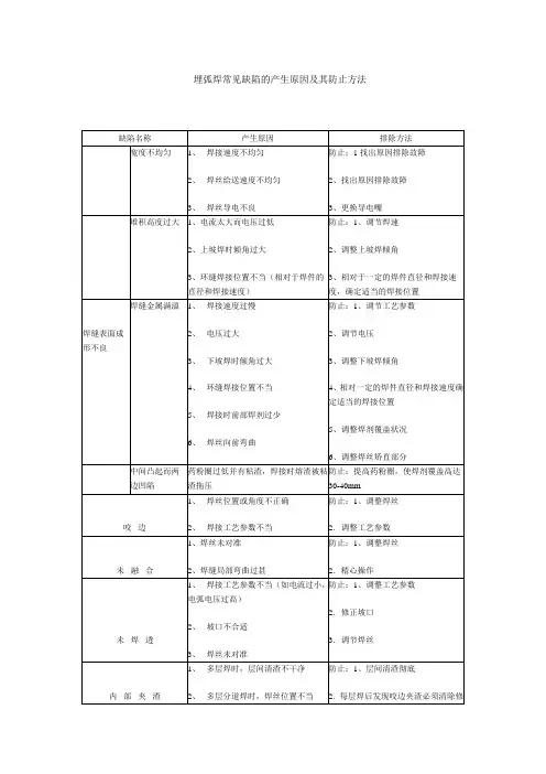
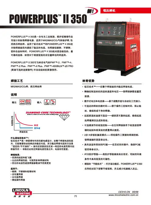
埋弧焊常见缺陷的产生原因及其防止方法林肯PowerPlus 系列焊机说明 (2010/07/12 16:45)(引用地址:未提供)目录: 公司动态浏览字体:大 中 小1PowerPlus 系列焊机 DIP 开关功能说明在处理客诉和回访时,发现很多客户对这些功能不太了解,有些客户在不了解的情况下 设置了这些开关,造成了设备使用上的故障。
这里对DIP 开关的功能作进一步说明。
一、位置和顺序复气 孔1、 焊剂未清理干净2、 焊剂潮湿3、 焊剂中有垃圾4、 焊剂覆盖层厚度不当或焊剂斗阻塞5、 焊丝表面清理不够6、 电压过高防止:1、接头必须清理干净 2.焊剂按规定烘干3.焊剂必须过筛、吹灰、烘干4.调节焊剂覆盖层高度,疏通焊剂斗 5.焊丝必须清理清理后应尽快使用 6.调整电压裂 纹1、 焊件焊丝焊剂等材料配合不当2、 焊丝中含碳、硫量较高3、 焊接区冷却速度过快而致热影响区硬化4、 多层焊的第一道焊缝截面过小5、 焊缝成形系数太小6、 焊接顺序不合理防止:1、合理选配焊接材料 2.选用合格焊丝3.适当降低焊速以及焊前预热和焊后缓冷4.调整工艺参数和改变极性 5.合理安排焊接顺序DIP 功能开关设在焊机主板上,面对焊机,从右手向左手数依次为1,2,3,4,5,6,7,8,该开关设置在上边为关,即OFF 状态;开关打在下边位置为开,即ON 状态。
下图为全关状态。
二、出厂设置1.PowerPlus 355/505 的标准出厂设置:DIP 开关从1 到8 分别为:关,关,关,开,开,开,关,关。
8 ONOFF7 6 5 4 3 2 18 ONOFF7 6 5 4 3 2 12该标准设置下的程序图如图1:2.PowerPlus II 的标准出厂设置:DIP 开关从1 到8 分别为:关,关,关,开,开,关,开,关。
注意:如果中继电缆长度小于10米应关闭第七个开关。
标准设置见下:8 ONOFF7 6 5 4 3 2 1焊枪开关ONOFFON送气输出电压ON送丝速度焊接电流OFFOFF焊接收弧回烧图1 焊接时序图(4步)3该标准设置下的焊接时序图如图2:三、注意事项每次重设DIP 开关时,要先关闭机器。
林肯电气公司是一家制造和销售高质量焊接设备、焊材和切割设备的企业。
本公司致力于满足客户的需求并超越其期望值。
有时买方可能会就使用林肯电气公司产品的情况向本公司咨询有关信息和建议,本公司将依据我们所掌握的最佳信息及时给予答复。
但是林肯电气公司对于所提供的建议信息不提供任何保证,不承担任何责任。
同时,我们也不会做任何形式的任何保证,包括对客户特别目的的适应性的保证。
实际上,一旦信息或者建议被提供,当资料被更新或者变更后,我们不承担任何责任,也不会提供更新后的信息或者建议,也不能扩大和更改产品销售上的保证。
林肯电气公司是一个积极满足客户需求的制造商,但是对林肯电气产品的选择和使用是由客户自己控制的,客户对自己的选择是要负全部责任的。
超出林肯电气公司控制范围的许多因素,会影响到应用这种类型制造方法和服务要求所产生的结果。
截止付印之前,本资料已反映了最精确的信息,如需最新信息,请参考
客户协助政策。
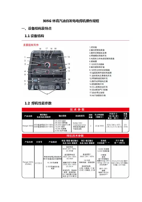
305G林肯汽油自发电电焊机操作规程一、设备结构及特点1.1设备结构1.2 焊机性能参数1.3 发动机性能参数1.4设备的特点:1、采用无刷发电机,维护保养简单。
2、焊接特点优异,可适合各种焊接需要。
3、采用钥匙启动或停机,高,低速运行也由开关控制。
4、装有怠速装置,节约能源。
怠速装置能在焊接作业或使用电源中稍适休息时自动调低发动机转速,达到节约能源,降低噪音的效果。
怠速装置不论对焊接作业还是交流电源都起作用,只要把IDLE 开关放在“ON”上即可。
三、操作方法3.1 启动前的检查:3.1.1、检查机油:发动前必须检查机油,机油位置应在上限FULL和下限ADD之间,检查时油标要完全插入,机油过多会造成发动机破损,必须十分注意。
运行中不得拔出油标尺,机油会喷出来,十分危险。
请使用API类SC级以上的机油,推荐使用SAE10W30全季节机油。
低质机油会影响发动机寿命。
不同品牌的机油不得混合使用。
3.1.2、检查燃料:请再启动前检查并加满燃料。
请用汽车用无铅汽油。
低质汽油会影响出力或造成故障。
3.1.3、检查电瓶:请每天检查电瓶液,定期清除电瓶端子的腐蚀情况。
电瓶液溅在身上或衣服上要立即冲洗。
3.1.4、检查线路:经常检查线路接头部有无松脱,断线,绝缘破损,以便及时处置。
以上检查完成后,启动机器,再注意一下有无漏油处。
3.2操作方法:1、将交流电开关设为OFF状态,使设备在无负荷状态下启动。
怠速开关拨至自动,焊接作业时,只要焊条接触母材,发动机瞬间即可升至额定转数。
当焊接中断7秒钟之后,发动机自动进入低速运转。
2、设备开关拨至START。
检查燃油油位及仪表是否指示正常。
3、拉开风门环。
4、按动启动按钮,设备启动后松手。
5、关闭风门环,怠速状态下暖机5分钟。
6、根据实际情况通过旋钮选择适合的焊接电流方式与电流大小,进行焊接。
7、工作中注意焊机是否有异常振动、声音或气味,电缆连接处是否有过热现象。
8、焊接作业完成后,设备开关拨至STOP,设备停止。
林肯DC1000焊机中文说明书IDEALARC DC-1000 IM420-A配合以下代码的机器使用:9919-9925 和10293注意安全,重在自己林肯电弧焊接和切割设备是以安全第一为准则进行设计和制造的。
但是,正确安装和操作更有利于保障您的人身安全。
禁止在没有通读此手册和所包含的安全规章情况下安装,使用或维修此设备。
更重要的是,客户在进行上述操作之前应考虑得当。
1安全!警告请确保所有的安装,操作,维护以及修理过程均由合格人员执行。
1.h. 为了防止烫伤,当发动机仍然热时严禁打开散热器压力盖!内燃机类设备1.a.在排除故障和维修前,应关闭发动机,除非维修工作需要它运转。
1.b.在开放,通风良好的地方操作发动机,或者将废气排到室外。
1.c.禁止在焊接电弧附近或当发动机运转时添加燃料。
在添加燃料前应使发动机停止转动并使其冷却,防止溅出的燃料挥发与热态的发动机部件接触而燃烧。
若燃料溅出,需擦净后才能启动发动机。
1.d.应使所有设备的安全防护罩,盖子和装置在适当位置并检修正常。
当起动,使用或维修设备时,手,头发,衣物和工具应远离V型皮带,齿轮,风扇和所有其它运动部件。
1.e.有些情况,需要拆除防护罩进行必要的维修。
切记只有在必要时才能拆下防护罩并且当维修结束后请迅速将其复原。
在运动部件附近工作时要格外小心。
1.f.禁止用手接近风扇。
当发动机工作时,禁止不顾调速器或空转轮而强行推动节气阀控制杆。
1.g.在维修时,当转动发动机或焊接电源时,为了防止意外起动汽油发电机,请断开火花塞接线,点火分配器顶盖或电磁发动机接线及其它。
电磁场对人体有害2.a.流过任何导体的电流会产生电磁场(EMF) 。
焊接电流在焊接电缆和焊机附近将产生EMF。
2.b. 在EMF区内心脏起搏器会受到干扰,带有心脏起搏器的焊工在焊接前应向医生咨询。
2.c.在焊接时暴露于EMF区情况下将对身体健康产生其它未知影响。
2.d. 所有焊工需执行下述步骤以减小焊接回路EMF区的暴露程度。
林肯焊机说明书Ⅰ.机械安装1.机头安装安装应牢固以防起弧时机头移动,注意机头与工作电缆应与地绝缘。
根据需要,可装在垂直调节器/水平调节器/行走小车上,所定的机头出厂前根据用户的订购模式安装送丝比率,当改变焊丝直径时需改变送丝轮和导向管。
对不同直径的焊丝需调节随动轮压力调节螺丝,焊丝分两档0.9-2.4mm和3.0-5.6mm。
根据需要调节,对较软的焊丝,压力宜小一点。
出厂时送丝轮设为正转(如图所示方向),但安装板可转动180º,并对换校直器和导电杆,送丝轮转动方向通过改变控制箱内接线上626,627号线来实现。
一般用25kg送丝盘。
NA-3S/NA-4/NA-3SF出厂时所装焊丝校直器的焊丝直径大于2mm以上。
机头安装好后,通过校直器和送丝导向管安装焊丝(其入口处为倒圆)而出丝导向管入口处为倒角)。
2.控制箱安装控制箱在标准行走小车或其它的机架上,当装在其它机架上时,打开控制箱后盖,按照控制箱底板上的安装孔固定控制箱。
3.导电杆组件国内一般常用K231 和K226●K231 导电杆组件:一般用于600A,更高电流可能引起导电嘴磨损坏。
适用于Ф2.4-5.6mm,对不同焊丝需不同导电嘴。
对Ф2.0-2.4mm焊丝还需导电嘴选配件和导丝管。
把工件电缆控制接到导电杆上,用螺栓拧紧,不用完全校直焊丝,以保持良好的电接触。
把焊剂漏斗的软管接到锥形组件的开口处。
要注意经常更换坏的导电嘴。
●K226 压钳式导电杆:一般用于600-1000A。
K226-T 由两个锥形夹组成用于Ф2.4-3.2mm。
K226R由一个锥形夹和一个方形夹组成,用于Ф3.2-5.6mm。
导电杆装在机头的下部,注意锥形夹的斜坡应朝向工件移动方向。
压钳应与导向管对直,通过调节夹钳一侧的螺丝来调节。
Ⅱ.电气安装1.电缆连接需600W,115V/50AC(其中,350W 给送丝电机和控制电路,250W 给行走电路)●从机头到控制箱:所有的工件电缆都接到控制箱后部,每个机头都带1.2m 长电机电缆和1.2m 长焊剂斗电缆,插到控制箱一侧对应的接口内。
IM303209/2016REV03CV 425 & 510 OPERATOR’S MANUALENGLISHLincoln Electric Bester Sp. z o.o.ul. Jana III Sobieskiego 19A, 58-263 Bielawa, Polandwww.lincolnelectric.euDeclaration of conformityLincoln Electric Bester Sp. z o.o.Declares that the welding machine: K14080-1A CV 425 AIR 230/400VK14081-1A CV 510 AIR 230/400Vconforms to the following directives:2014/35/EU, 2014/30/EUand has been designed in compliance with thefollowing standards:EN 60974-1:2012, EN 60974-10:201420.04.2016Piotr SpytekOperations DirectorLincoln Electric Bester Sp. z o.o., ul. Jana III Sobieskiego 19A, 58-263 Bielawa, Poland12/0512/05 THANKS! For having chosen the QUALITY of the Lincoln Electric products.∙Please Examine Package and Equipment for Damage. Claims for material damaged in shipment must be notified immediately to the dealer.∙For future reference record in the table below your equipment identification information. Model Name, Code & Serial Number can be found on the machine rating plate.Model Name: ………………………………………………………………………………………………………………………………………….Code & Serial Number: ………………………………………………………………….. …………………………………………………………………..Date & Where Purchased …………………………………………………………………. …………………………………………………………………..ENGLISH INDEXSafety (1)Installation and Operator Instructions (2)Electromagnetic Compatibility (EMC) (5)Technical Specifications (6)WEEE (7)Spare Parts (7)Electrical Schematic (7)Accessories (7)Safety11/04WARNINGThis equipment must be used by qualified personnel. Be sure that all installation, operation, maintenance and repair procedures are performed only by qualified person. Read and understand this manual before operating this equipment. Failure to follow the instructions in this manual could cause serious personal injury, loss of life, or damage to this equipment. Read and understand the following explanations of the warning symbols. Lincoln Electric is not responsible for damages caused by improper installation, improper care or abnormal operation.The manufacturer reserves the right to make changes and/or improvements in design without upgrade at the same time the operator’s manual.Installation and Operator InstructionsRead this entire section before installation or operationof the machine.Location and EnvironmentThis machine will operate in harsh environments.However, it is important that simple preventativemeasures are followed to assure long life and reliableoperation:∙Do not place or operate this machine on a surfacewith an incline greater than 15° from horizontal.∙Do not use this machine for pipe thawing.∙This machine must be located where there is freecirculation of clean air without restrictions for airmovement to and from the air vents. Do not coverthe machine with paper, cloth or rags when switchedon.∙Dirt and dust that can be drawn into the machineshould be kept to a minimum.∙This machine has a protection rating of IP23. Keep itdry when possible and do not place it on wet groundor in puddles.∙Locate the machine away from radio controlledmachinery. Normal operation may adversely affectthe operation of nearby radio controlled machinery,which may result in injury or equipment damage.Read the section on electromagnetic compatibility inthis manual.∙Do not operate in areas with an ambient temperaturegreater than 40°C.Duty cycle and OverheatingThe duty cycle of a welding machine is the percentage oftime in a 10 minute cycle at which the welder canoperate the machine at rated welding current.Example: 60% duty cycleWelding for 6 minutes. Break for 4 minutes.Excessive extension of the duty cycle will cause thethermal protection circuit to activate.MinutesordecreaseDuty CycleThe machine is protected from overheating by atemperature sensor.Input Supply ConnectionCheck the input voltage, phase, and frequency suppliedto this machine before turning it on. Verify theconnection of grounding wires from the machine to theinput source. The allowable input voltages are 3x230V50/60Hz and 3x400V 50/60Hz (3x400V: factory default).For more information about input supply refer to thetechnical specification section of this manual and to therating plate of the machine.If it is necessary to change the input voltage:∙The input cable must be disconnected from themains supply and the machine switched OFF.∙Remove the left side panel.∙Reconnect X6 according to the diagram below:indicate the machine is ready to weld.(see ”Accessories” section, Source/wire feeder cable K10347-PG-xM or K10347-PGW-xM).Use the shortest possible cable lengthsMachine and Circuit ProtectionThe CV425 / CV510 is protected against overheating, overload and accidental short-circuitsIf the machine is overheated, the thermal protection circuit will decrease the output current to 0. The thermal protection indicator [3] will turn on. The thermalprotection circuit will turn on the output current again, when the machine is cooled.section to eliminate or reduce the amount of electromagnetic disturbance generated by this machine..This machine has been designed to operate in an industrial area. To operate in a domestic area it isnecessary to observe particular precautions to eliminate possible electromagnetic disturbances. Theoperator must install and operate this equipment as described in this manual. If any electromagneticdisturbances are detected the operator must put in place corrective actions to eliminate these disturbances with, if necessary, assistance from Lincoln Electric.Before installing the machine, the operator must check the work area for any devices that may malfunction because of electromagnetic disturbances. Consider the following.∙Input and output cables, control cables, and telephone cables that are in or adjacent to the work area and the machine.∙Radio and/or television transmitters and receivers. Computers or computer controlled equipment.∙Safety and control equipment for industrial processes. Equipment for calibration and measurement.∙Personal medical devices like pacemakers and hearing aids.∙Check the electromagnetic immunity for equipment operating in or near the work area. The operator must be sure that all equipment in the area is compatible. This may require additional protection measures.∙The dimensions of the work area to consider will depend on the construction of the area and other activities that are taking place.Consider the following guidelines to reduce electromagnetic emissions from the machine.∙Connect the machine to the input supply according to this manual. If disturbances occur if may be necessary to take additional precautions such as filtering the input supply.∙The output cables should be kept as short as possible and should be positioned together. If possible connect the work piece to ground in order to reduce the electromagnetic emissions. The operator must check that connecting the work piece to ground does not cause problems or unsafe operating conditions for personnel and equipment.∙Shielding of cables in the work area can reduce electromagnetic emissions. This may be necessary for specialWARNINGTechnical SpecificationsNAME INDEXCV 425 K14080-1ACV 510 K14081-1AINPUTInput Voltage U1EMC Group / Class FrequencyCV 425 230 / 400V±10%3 - phases II / A 50 / 60 HzCV 510Input Power at Rated Cycle InputAmperesI1max cosφCV 425 23 kVA @ 60% Duty Cycle 57 A 0,89CV 510 29,2 kVA @ 60% Duty Cycle 73 A 0,89RATED OUTPUTDuty Cycle 40°C(based on a 10 min. period)Output Current Output VoltageCV 425 60% 420A 35Vdc 100% 325A 30,3Vdc CV 510 60% 500A 39Vdc 100% 385A 33,3VdcOUTPUT RANGEWelding Current Range Open Circuit VoltageCV 425 10A ÷ 420A 10 ÷ 39 VdcCV 510 10A ÷ 500A 10 ÷ 39 VdcRECOMMENDED INPUT CABLE AND FUSE SIZESFuse or Circuit Breaker Size Power Lead230V 400VCV 425 D63A D32A 4 Conductor, 6 mm2CV 510 D63A D32A 4 Conductor, 10 mm2DIMENSIONWeight Height Width LengthCV 425 152 kg 880 mm 696 mm 1020 mmCV 510 160 kg 880 mm 696 mm 1020 mmProtection Rating Operating Humidity(t=20°C)Operating Temperature StorageTemperatureIP23 ≤ 90 % from -10 ºC to +40 ºC from -25 ºC to +55 ºCWEEE07/06 Spare Parts12/05 Part list reading instructions∙Do not use this part list for a machine if its code number is not listed. Contact the Lincoln Electric Service Department for any code number not listed.∙Use the illustration of assembly page and the table below to determine where the part is located for your particular code machine.∙Use only the parts marked "●" in the column under the heading number called for in the assembly page (# indicatea change in this printing).First, read the Part List reading instructions above then refer to the "Spare Part" manual supplied with the machine, which contains a picture-descriptive part number cross-reference).Electrical SchematicRefer to the "Spare Parts" manual supplied with the machine.AccessoriesK10347-PG-xxM Source/wire feeder cable (gas). Available in 5, 10, 15m.K10347-PGW-xxM Source/wire feeder cable (gas and water). Available in 5, 10 or 15m.K14009-1 CO2 Socket Kit.K14082-1 AV Meter Kit.Kit.K14071-2 GrillK14037-1 Cooler COOLARC 25.。
®®the leader in technology and service!Small Package . . .Superior Performancethe little guys that can run with the big boys!DC Inverter Arc WeldersS Models(Stick/Lift TIG)•130S •150S •190S GTS Models(Stick/Lift TIG/HF TIG)•130GTS •150GTS •190GTS•Superior performance for TIG/Stick Applications- the popular Lincoln ®5P - other Cellulose and Rutile Electrodes - Stainless Steel and Low Hydrogen Electrodes - Lift TIG GTAW - High frequency TIG (GTS models only)•Operation on 115/208/220/230 VAC •Weighs less than 19 lbs/8.5 kg •Up to 190 amps of output®Lincoln and 5P are trademarks of the Lincoln Electric CompanyProcess Selection•Stick•Lift Start TIGCurrent Control5 to MachineMaximum AmperageHot Start - 0-100AStick OnlyWarning LightIndicates improper input voltage or temperature overload when litPower LightIndicates Power Service ONRemote 8 PIN Control Connector•Current Control Remote •ON/OFF Weld CurrentPulse Frequency2 Ranges (.5 - 25 Hz)(10 - 500 Hz)Pulse•Off•High Range (.5 - 25 Hz) Select •Low Range (10 - 500 Hz) SelectProcess Selection•Stick•Lift Start TIG•High Frequency Start TIGHot Start - 0-100ATIG HF Start and StickCurrent Control5 to MachineMaximum AmperageUpslope .5-5 sec Downslope 1.0-10 sec Spot Timer .5-5 sec Slope - OnSpot Timer/Sloper - Off Spot Timer - OnWarning LightIndicates improper input voltage or temperature overload when litPower LightIndicates Power Service ONRemote 8 PIN Control Connector•Current Control Remote •ON/OFF Weld CurrentS SeriesThe S Series is available in models with maximum current outputs of 130, 150 and 190 amps. These machines are excellent for Stick welding applications up to their rated output. They are provided with an adjustable hot start and automatically adjusted arc control for smooth and easy operation with all electrodes.The S Series also provides high quality TIG results when operating in the Lift TIG mode. No high frequency is used. Simply touch the electrode to the work and lift, and the TIG arc is initiated with no high frequency and no damage to the tungsten electrode.It can be used for industrial/maintenance applications on 208/230VAC or home/utility applications on 115 VAC. All machines are pro-vided with Smart Link™ capability to automatically link to either 115or 208/230 VAC.GTS SeriesThe GTS Series offers all of the same capabilities as the S Series as well as many TIG controls to master those applications where tight control and high quality are required. The standard controls provid-ed on all GTS machines are a gas valve, upslope and downslope, spot timer, pulser, and high frequency starting. A fixed preflow is provid-ed and postflow is automatically adjusted by the current level.ApplicationsBoth S and GTS Series are excellent for construction, maintenance,HVAC, fabricators, manufacturing, contractors, utility, farm and home. Please refer to the specifications for recommended operation of the machines.MACHINESACCESSORIESDISTRIBUTED BY:International Customer Service Thermadyne Canada Thermadyne UK Thermadyne Asia Sdn. Bhd.Cigweld Australia Oakville, Ontario, Canada Oakville, Ontario Canada Chorley, England Kuala Lumpur, Malaysia Melbourne, Australia Ph: (1) 905-827-9777Ph: (1) 905-827-1111Ph: (44) 1257-261755Ph: (60) 3-692-2988Ph: (61) 3-9487-1234Fax: (1) 905-827-9797Fax: (1) 905-827-3648Fax: (44) 1257-224800Fax: (60) 3-692-1085Fax: (61) 3-9487-1487Thermadyne do Brasil Thermadyne Middle East Thermadyne de Mexico Thermadyne Japan Thermadyne EuropeSao Paulo, Brazil Dubai, United Arab Emirates Mexico City, Mexico Osaka, Japan Milan, ItalyPh: (55) 11-744-3444Ph: (971) 4-632-400Ph: (52) 5696-7407Ph: (81) 6-4809-8411Ph: (39) 039-204-991Fax: (55) 11-453-2260Fax: (971) 4-631-781Fax: (52) 5696-7757Fax: (81) 6-4809-8412Fax: (39) 039-204-9922U.S. CUSTOMER SERVICE: 2200 Corporate Drive 800-255-5846 • FAX 800-332-0946International OfficesForm No. 0-0820 (6/99)©Thermal Arc Inc., 1997Printed in U.S.A.。
操作员手册请注册您的机器:/register 搜索授权维修商和分销商: /locatorIM C 10370 | 发布日期 2016年9月Lincoln Global, Inc. 保留所有权利。
使用本手册的机器代码是:12643!˖保持供未来参考购买日期代码:(如:10859)序列号:(如: U1060512345)目录产品描述 (3)设备局限 (3)设计特点 (3)安装 .......................................................................A部分技术规格 .........................................................................A-1机器接地 .........................................................................A-2位置与冷却通风 ....................................................................A-2高频保护 .........................................................................A-2升举.........................................................................A-2堆垛 .........................................................................A-2倾斜.........................................................................A-2环境局限性.........................................................................A-2箱前控制 .........................................................................A-3箱后控制 .........................................................................A-4电弧焊的推荐焊条和作业电缆尺寸 .....................................................A-7控制电缆与电压传感连接.............................................................A-8TYPICA;集成系统(单ARM)...........................................................A-9操作 .......................................................................B部分通电顺序 .........................................................................B-1负载周期.........................................................................B-2常见焊接工艺.......................................................................B-3配件 .......................................................................C部分维护 .......................................................................D部分目视检查 .........................................................................D-1例行维护 .........................................................................D-1定期维护 .........................................................................D-1故障排除 .......................................................................E部分如何使用故障排除指南...............................................................E-1用状态灯解决系统问题...............................................................E-2POWER WAVE的错误代码 ..............................................................E-3图 ...........................................................................F部分零部件清单可能会在未给出通知的情况下修改或升级内容/详情。