NT90RHCDAC12VCB0.6中文资料
- 格式:pdf
- 大小:305.76 KB
- 文档页数:3

14位, 165M SPA(采样率)DAC(数模转换器)特性:●单电源供电+5V或+3V●高SFDR (无杂散动态范围): 在100MSPS 64dBc时20MHz输出●低干扰: 3PV -S●低功耗: 170MW (+5 V时)应用●通讯传输通道WLL , 蜂窝基站数字微波链路电缆调制解调器●波形产生直接数字频率合成器(DDS )任意波形发生器(ARB )●医疗/超声●高速仪表和控制●视频, 数字电视说明:DAC904是一款高速数模转换器, 14位分辨率, 引脚兼容DAC908、DAC900、DAC902, 分别提供8-, 10-, 12-位分辨率选择。
该系列DAC支持的所有型号更新率超过165MSPS, 具有优良的动态性能。
DAC904先进分割架构的优化为单音和多频音信号提供高无杂散动态范围(SFDR), 特别是用于通信系统的发送信号电路时。
DAC904具有高阻抗(200KΩ)的电流输出, 标称范围为20mA和一个最多为1.25V的输出。
差分输出允许两个差分或单端模拟信号的接口。
电流输出的匹配保证在差分结构中杰出的动态性能, 它可以与变压器配合使用。
运用一个小的几何CMOS工艺, 单片DAC904可以用在+2.7 V至+5.5 V宽的单电源范围内操作。
其低功耗特性允许它使用在便携式和电池供电系统情况下。
可通过减少输出电流与调整满量程选项实现进一步优化。
DAC904不断运转时, 掉电模式导致其待机功率仅为为45mW 。
DAC904带有一个集成的1.24V带隙基准和边沿触发输入锁存器, 提供完整的转换器解决方案。
+3 V和+5 V CMOS逻辑系列都可以接口到DAC904 。
DAC904的参考结构允许使用芯片上的参考, 或施加外部参考。
通过一个外部电阻, 满量程输出电流可以调整在2 - 20mA, 并保持其指定的动态性能。
DAC904采用SO -28和TSSOP -28封装。
绝对最大额定值+VA到AGND(模拟信号地)......-0.3V至+6V+VD到DGND(数字信号地)......-0.3V到+6VAGND到DGND......-0.3V到+0.3V+VA 到+VD......-6V到+6VCLK, PD到DGND......-0.3V到VD+0.3VD0-D13到DGND......-0.3V到VD+0.3VIOUT, I 到AGND......-1V到VA+0.3VBW,BYP到AGND......-0.3V到VA+0.3VREFIN ,FSA到AGND......-0.3V到VA+0.3VINT/EXT到AGND......-0.3V到VA+0.3V结温度. . . . . . . +150℃存储器温度. . . . . . +125℃防静电敏感度这种集成的电路可以被ESD(静电释放)损坏。


Series 9Japan/UK 97318678/III-15Series 9Serie s 99090ccSeries 9Series 9EnglishOur products are designed to meet the highest standards of quality, functionality and design. Thank you for your trust in Braun’s quality, and we hope you enjoy your new Braun shaver.Read these instructions completely, they contain safety information. Keep them for future reference.WarningYour appliance is provided with a special cord set, which has an integrated Safety Extra Low Voltage power supply. Do not exchange or tamper with any part of it, otherwise there is risk of an electric shock. Only use the special cord set provided with your appliance.The shaver is suitable for cleaningunder running tap water. Detachthe shaver from the power supplybefore cleaning it in water.Models 9095cc w&d/9093s w&d/9080cc w&d/9040s w&d only:This appliance is suitable forcleaning under running water anduse in a bath or shower. For safetyreasons it can only be operatedcordlessly.Note: Only models 9093s w&d and 9040s w&d can be used with foam or gel. Do not shave with a damaged foil or cord. This appliance can be used by children aged from 8 years and above and per-sons with reduced physical, sensory or mental capabilities or lack of experience and knowledge if they have been given supervision or instruction concerning the safe use of the appliance and under-stand the hazards involved. Children shall not play with the appliance. Clean-ing and user maintenance shall not be made by children unless they are older than 8 years and supervised.Oil bottle (not with all models)Keep out of reach of children. Do not swallow. Do not apply to eyes. Dispose of properly when empty.Clean&Charge Station (models9095cc w&d/9090cc/9080cc w&d/ 9075cc/9070cc/9050cc)To prevent the cleaning fluid from leaking, ensure that the Clean&Charge Station is placed on a flat surface. When a cleaning cartridge is installed, do not tip, move suddenly or transport the station in any way as cleaning fluid might spill out of the cartridge. Do not place the station inside a mirror cabinet, nor place it on a polished or lacquered surface. The cleaning cartridge contains a highly flammable liquid so keep it away from sources of ignition. Do not expose to direct sunlight and cigarette smoking nor store it over a radiator.Do not refill the cartridge and use only original Braun refill cartridges.1 Foil & Cutter cassette2 Cassette release buttons3 MultiHeadLock switch4 On/off switch5 Shaver display6 Long hair trimmer7 Shaver-to-stationcontacts8 Release button for long hair trimmer9 Model number of shaver10 Shaver power socket11 Special cord set12 Brush13 Hard travel casePrior to first use remove the protection foil if any from the shaver display. Connect the shaver to an electrical outlet by snapping the special cord set (11) into the power socket (10) or for cc models via the Clean&Charge Station (see Chapter «Clean&Charge Station»).Charging and basic operating information• When charging for the first time, charge continuously for 1 hour.• A full charge provides up to 50 minutes of cordless shaving time. This may vary according to your• Recommended ambient temperature for charging is 5 °C to 35 °C. The battery may not charge properly or at all under extreme low or high temperatures.• Recommended ambient temperature for shaving is 15 °C to 35 °C.• Do not expose the appliance to temperatures higher than 50 °C for extended periods of time.• When the shaver is connected to an electrical outlet, it may take some minutes until the display illuminates.Charge statusThe shaver display (5) shows the charge status of the battery when connected to an electrical outlet:• During charging the respective battery segment will blink.• When fully charged all battery segments will light up for a few seconds then the display turns off. Low chargeThe low-charge light flashes red when the battery is running low. You should be able to finish your shave. With switching off the shaver a beep sound reminds of the low charge status.Models 9095cc w&d/9093s w&d/9090cc: The last9 minutes of remaining shaving time are displayed in digits.Cleaning status (models 9095cc w&d/9090cc/ 9080cc w&d/9075cc/9070cc/9050cc)Travel lockThe lock symbol lights up when the shaver has been locked to avoid unintended starting of the motor (e.g. for storing in a suitcase).Press the on/off switch (4) to operate the shaver. Tips for a perfect dry shave1. Always shave before washing your face.2. At all times, hold the shaver at the right angle(90°) to your skin.3. Stretch your skin and shave against thedirection of your beard growth.MultiHeadLock switch (head lock)To shave hard-to-reach areas (e.g. under the nose) slide the MultiHeadLock switch (3) down to lock the shaver head. The shaver head can be locked in five positions. To change position, move the shaver head with your thumb and forefinger back or forth. It will Models 9095cc w&d/9090cc/9080cc w&d/9075cc/ 9070cc/9050cc: For automatic cleaning in theClean&Charge Station the head lock should be released. Long hair trimmerTo trim sideburns, moustache or beard press the release button (8) and slide the long hair trimmer (6) upwards.Shaving with the cord (not for models 9095cc w&d/ 9093s w&d/9080cc w&d/9040s w&d)If the shaver has run out of power (discharged), you may also shave with the shaver connected to an electrical outlet via the special cord set.Travel lock• Activation: By pressing the on/off switch (4) for3 seconds the shaver is locked. This is confirmed by a beep sound and the lock symbol in the display. Afterwards the display turns off.• Deactivation: By pressing the on/off switch for3 seconds the shaver is unlocked again.Cleaning under running water• Switch on the shaver (cordless) and rinse the shaver head under hot running water until all residues have been removed. You may use liquid soap without abrasive substances. Rinse off all foam and let the shaver run for a few more seconds.• Next, switch off the shaver, press the release buttons (2) to remove the Foil & Cutter cassette (1) and let it dry completely.• If you regularly clean the shaver under water, then apply once a week a drop of light machine oil on top of the Foil & Cutter cassette.Models 9093s w&d/9040s w&d only: The shaver should be cleaned after each foam usage. Cleaning with a brush• Switch off the shaver. Remove the Foil & Cutter cassette (1) and tap it out on a flat surface. Using the brush, clean the inner area of the pivoting head. Do not clean the cassette with the brush as this may damage it!The Foil & Cutter cassette can be attached either way. There is no impact on the shaving performance. The Clean&Charge Station has been developed for cleaning, charging, lubricating, disinfecting, drying14 Station power socket15 Lift button for cartridge exchange16 Station-to-shaver contacts17 Clean&Charge Station display17a L evel indicator17b Status light17c Cleaning program indicator (models 9095cc w&d/ 9090cc/9080cc w&d/9075cc only)18 Start button19 Cleaning cartridgeInstalling the Clean&Charge Station (see fig. D)• Remove the protection foil if any from theClean&Charge Station display.• Press the lift button (15) at the rear side of the Clean&Charge Station to lift up the housing.• Hold the cleaning cartridge (19) down on a flat, stable surface (e.g. table).• Carefully remove the lid from the cartridge.• Slide the cartridge from the rear side into the base of the station until it snaps into place.• Slowly close the housing by pushing it down until it locks.• Connect the station to an electrical outlet by snapping the special cord set (11) into the power socket (14).Charging the shaver in the Clean&Charge Station (see fig. D)Insert the shaver head with the front showing and released head lock into the cleaning station. Important: The shaver needs to be dry and free from any foam or soap residue!The contacts (7) on the back of the shaver need to align with the contacts (16) in the station. Push the shaver in the correct position. A beep sound confirms that the shaver sits properly in the station. Charging will start automatically.Cleaning the shaver (see fig. D)Station, as described above and press the start button (18).The hygiene status will be analyzed and is shownby the cleaning program indicators (17c) in the Clean&Charge Station display (models 9095cc w&d/ 9090cc/9080cc w&d/9075cc only).If status light (17b) does not shine (Clean&Charge Station switches to stand-by after ca. 10 minutes), press start button twice. Otherwise cleaning will not start. For best shaving results, we recommend cleaning after each shave.The cleaning process consists of several cycles, in which cleaning fluid is flushed through the shaver head. Depending on your Clean&Charge Station model and/or program selected, the cleaning time takes up to 3 minutes, followed by an active drying phase of about 40 minutes, during which a fan is running.Afterwards charging will resume, which is indicated in the shaver display. When the shaver is fully charged the display turns off.Cleaning programsshort economical cleaningnormal level of cleaninghigh intensive cleaningModels 9070cc/9050cc:One standard cleaning program is included. Removing the shaver from the Clean&Charge Station (see fig. E)Hold the Clean&Charge Station with one hand and tilt the shaver slightly to the front to release it. Cleaning Cartridge / Replacement (see fig. F)When the level indicator (17a) lights up permanently red, the remaining fluid in the cartridge is sufficient for about 3 more cycles. When the level indicator blinks red, the cartridge needs to be replaced (about every 3 weeks when used daily).After having pressed the lift button (15) to open the housing, wait for a few seconds before removing the used cartridge to avoid any dripping. Before discarding the used cartridge, make sure to close the openings using the lid of the new cartridge, since the used cartridge will contain contaminated cleaning solution.The hygienic cleaning cartridge contains denatured ethanol (specification see cartridge), which once opened will naturally evaporate slowly. Each cartridge, if not used daily, should be replaced after approximately 8 weeks to ensure optimal disinfection. The cleaning cartridge also contains lubricants for the shaving system, which may leave residual marks on the outer foil frame and the cleaning chamber of the Clean&Charge Station. These marks can be removed easily by wiping gently with a damp cloth. Braun recommends changing your shaver’s Foil & Cutter cassette every 18 months to maintain your shaver‘s maximum performance.Available at your dealer or Braun Service Centres:• Foil & Cutter cassette: 90S/90B• Cleaning cartridge Clean&Charge Station: CCR • Braun Shaver cleaner sprayThe cleaning cartridge can be disposed of with regular household waste.Subject to change without notice.For electric specifications, see printing on thespecial cord set.。

TL H 5690MICRO-DAC DAC1208 DAC1209 DAC1210 DAC1230 DAC1231 DAC123212-Bit m P Compatible Double-Buffered D to A ConvertersFebruary1995 MICRO-DAC TM DAC1208 DAC1209 DAC1210 DAC1230 DAC1231 DAC123212-Bit m P CompatibleDouble-Buffered D to A ConvertersGeneral DescriptionThe DAC1208and the DAC1230series are12-bit multiply-ing D to A converters designed to interface directly with awide variety of microprocessors(8080 8048 8085 Z-80etc ) Double buffering input registers and associated con-trol lines allow these DACs to appear as a two-byte‘‘stack’’in the system’s memory or I O space with no additional in-terfacing logic requiredThe DAC1208series provides all12input lines to allow sin-gle buffering for maximum throughput when used with16-bitprocessors These input lines can also be externally config-ured to permit an8-bit data interface The DAC1230seriescan be used with an8-bit data bus directly as it internallyformulates the12-bit DAC data from its8input lines All ofthese DACs accept left-justified data from the processorThe analog section is a precision silicon-chromium(Si-Cr)R-2R ladder network and twelve CMOS current switchesAn inverted R-2R ladder structure is used with the binaryweighted currents switched between the I OUT1and I OUT2maintaining a constant current in each ladder leg indepen-dent of the switch state Special circuitry provides TTL logicinput voltage level compatibilityThe DAC1208series and DAC1230series are the12-bitmembers of a family of microprocessor compatible DACs(MICRO-DACs TM) For applications requiring other resolu-tions the DAC1000series for10-bit and DAC0830seriesfor8-bit are available alternativesFeaturesY Linearity specified with zero and full-scale adjust onlyY Direct interface to all popular microprocessorsY Double-buffered single-buffered or flow through digitaldata inputsY Logic inputs which meet TTL voltage level specs(1 4Vlogic threshold)Y Works with g10V reference full4-quadrantmultiplicationY Operates stand-alone(without m P)if desiredY All parts guaranteed12-bit monotonicY DAC1230series is pin compatible with the DAC0830series8-bit MICRO-DACsKey SpecificationsY Current Settling Time1m sY Resolution12BitsY Linearity(Guaranteedover temperature)10 11 or12Bits of FSY Gain Tempco1 3ppm CY Low Power Dissipation20mWY Single Power Supply5V DC to15V DC Typical ApplicationTL H 5690–1TRI-STATE is a registered trademark of National Semiconductor CorpMICRO-DAC TM is a trademark of National Semiconductor CorpC1995National Semiconductor Corporation RRD-B30M115 Printed in U S AAbsolute Maximum RatingsIf Military Aerospace specified devices are required please contact the National Semiconductor Sales Office Distributors for availability and specifications (Notes 1and 2)Supply Voltage (V CC )17V DC Voltage at Any Digital Input V CC to GNDVoltage at V REF Inputg 25VStorage Temperature Rangeb 65 C to a 150 CPackage Dissipation at T A e 25 C 500mW(Note 3)DC Voltage Applied to I OUT1or I OUT2(Note 4)b 100mV to V CCESD Susceptability800VOperating ConditionsLead Temperature (Soldering 10sec )300 CTemperature RangeT MIN s T A s T MAXDAC1208LCJ DAC1209LCJ DAC1210LCJ DAC1230LCJ DAC1231LCJ DAC1232LCJDAC1231LIN DAC1232LINb 40 C s T A s a 85 C DAC1208LCJ-1 DAC1210LCJ-1 DAC1230LCJ-1 DAC1231LCJ-1 DAC1232LCJ-1 DAC1231LCN DAC1232LCN DAC1231LCWM DAC1232LCWM 0 C s T A s a 70 C Range of V CC 4 75V DC to 16V DC Voltage at Any Digital InputV CC to GNDElectrical CharacteristicsV REF e 10 000V DC V CC e 11 4V DC to 15 75V DC unless otherwise noted Boldface limits apply from T MIN to T MAX (seeNote 13) all other limits T A e T J e 25 CTyp Tested Design ParameterConditions Notes(Note 10)Limit Limit Units (Note 5)(Note 6)Resolution121212BitsLinearity ErrorZero and Full-Scale 4 7 13(End Point Linearity)AdjustedDAC1208 DAC1230g 0 018g 0 018%of FSR DAC1209 DAC1231g 0 024g 0 024%of FSR DAC1210 DAC1232g 0 050g 0 05%of FSRDifferential Non-Linearity Zero and Full-Scale 4 7 13AdjustedDAC1208 DAC1230g 0 018g 0 018%of FSR DAC1209 DAC1231g 0 024g 0 024%of FSR DAC1210 DAC1232g 0 050g 0 05%of FSR Monotonicity 4121212Bits Gain Error (Min)Using Internal R Fb 7b 0 10 0%of FSR Gain Error (Max)V ref e g 10V g 1V7b 0 1b 0 2%of FSRGain Error Tempco 7g 1 3g 6 0ppm of FS C Power Supply RejectionAll Digital Inputs 7g 3 0g 30ppm of FSR VLatched HighReference Input Resistance (Min)13151010k X Reference Input Resistance (Max)152020Output Feedthrough ErrorV REF e 20Vp-p f e 100kHz All Data Inputs Latched 93 0mVp-pLowOutput CapacitanceAll Data Inputs I OUT1200pF Latched High I OUT270pF All Data Inputs I OUT170pF Latched LowI OUT2200pF Supply Current Drain 132 02 5mA Output Leakage Current I OUT1All Data Inputs Latched 11 130 11515nA LowI OUT2All Data Inputs Latched 11 130 11515nA HighDigital Input Threshold Low Threshold 130 80 8V DC High Threshold 132 22 2V DC Digital Input CurrentsDigital Inputs k 0 8V 13b 200b 200m A DC Digital Inputs l 2 2V131010m A DC2Electrical Characteristics(Continued)V REF e10 000V DC V CC e11 4V DC to15 75V DC unless otherwise noted Boldface limits apply from T MIN to T MAX(see Note13) all other limits T A e T J e25 CSee Typ Tested DesignSymbol Parameter ConditionsNote(Note10)Limit Limit Units (Note5)(Note6)AC CHARACTERISTICSt s Current Setting Time V IL e0V V IH e5V1 0m st W Write and XFER V IL e0V V IH e5V850320Pulse Width Min 320t DS Data Setup Time Min V IL e0V V IH e5V70320320t DH Data Hold Time Min V IL e0V V IH e5V3090ns90t CS Control Setup Time Min V IL e0V V IH e5V60320320t CH Control Hold Time Min V IL e0V V IH e5V010Note1 Absolute Maximum Ratings indicate limits beyond which damage to the device may occur DC and AC electrical specifications do not apply when operating the device beyond its specified operating conditionsNote2 All voltages are measured with respect to GND unless otherwise specifiedNote3 This500mW specification applies for all packages The low intrinsic power dissipation of this part(and the fact that there is no way to significantly modify the power dissipation)removes concern for heat sinkingNote4 Both I OUT1and I OUT2must go to ground or the virtual ground of an operational amplifier The linearity error is degraded by approximately V OS d V REF For example if V REF e10V then a1mV offset V OS on I OUT1or I OUT2will introduce an additional0 01%linearity errorNote5 Tested and guaranteed to National’s AOQL(Average Outgoing Quality Level)Note6 Design limits are guaranteed but not100%tested These limits are not used to calculate outgoing quality levels Guaranteed for V CC e11 4V to15 75V and V REF e b10V to a10VNote7 The unit FSR stands for full-scale range Linearity Error and Power Supply Rejection specs are based on this unit to eliminate dependence on a particular V REF value to indicate the true performance of the part The Linearity Error specification of the DAC1208is0 012%of FSR(max) This guarantees that after performing a zero and full-scale adjustment the plot of the4096analog voltage outputs will each be within0 012%c V REF of a straight line which passes through zero and full-scale The unit ppm of FSR(parts per million of full-scale range)and ppm of FS(parts per million of full-scale)are used for convenience to define specs of very small percentage values typical of higher accuracy converters In this instance 1ppm of FSR e V REF 106is the conversion factor to provide an actual output voltage quantity For example the gain error tempco spec of g6ppm of FS C represents a worst-case full-scale gain error change with temperature from b40 C to a85 C of g(6)(V REF 106)(125 C)or g0 75(10b3)V REF which is g0 075%of V REFNote8 This spec implies that all parts are guaranteed to operate with a write pulse or transfer pulse width(t W)of320ns A typical part will operate with t W of only 100ns The entire write pulse must occur within the valid data interval for the specified t W t DS t DH and t S to applyNote9 To achieve this low feedthrough in the D package the user must ground the metal lid If the lid is left floating the feedthrough is typically6mVNote10 Typicals are at25 C and represent the most likely parametric normNote11 A10nA leakage current with R Fb e20k and V REF e10V corresponds to a zero error of(10c10b9c20c103)c100%10V or0 002%of FSNote12 Human body model 100pF discharged through a1 5k X resistorNote13 Tested limit for b1suffix parts applies only at25 CConnection DiagramsDual-In-Line Package Dual-In-Line PackageTL H 5690–2See Ordering Information3Switching WaveformsTL H 5690–3Typical Performance CharacteristicsDigital Input Threshold vs V CCDigital Input Threshold vs TemperatureGain and Linearity Error Variation vs TemperatureGain and Linearity Error Variation vs Supply VoltageControl Set-Up Time t CS Data Hold Time t DHWrite Pulse Width t W Data Set-Up Time t DSTL H 5690–44Definition of Package Pinouts CONTROL SIGNALS(all control signals are level actuated) CS Chip Select(active low) The CS will enable WR1WR1 Write1 The active low WR1is used to load the digital data bits(DI)into the input latch The data in the input latch is latched when WR1is high The12-bit input latch is split into two latches One holds the first8bits while the other holds4bits The Byte1 Byte2control pin is used to select both latches when Byte1 Byte2is high or to overwrite the 4-bit input latch when in the low stateByte1 Byte2 Byte Sequence Control When this control is high all12locations of the input latch are enabled When low only the four least significant locations of the input latch are enabledWR2 Write2(active low) The WR2will enable XFER XFER Transfer Control Signal(active low) This signal in combination with WR2 causes the12-bit data which is available in the input latches to transfer to the DAC register DI0to DI11 Digital Inputs DI0is the least significant digital input(LSB)and DI11is the most significant digital input (MSB)I OUT1 DAC Current Output1 I OUT1is a maximum for a digital code of all1s in the DAC register and is zero for all 0s in the DAC registerI OUT2 DAC Current Output2 I OUT2is a constant minus I OUT1 or I OUT1a I OUT2e constant(for a fixed reference voltage) This constant current isV REF c 1b14096Jdivided by the reference input resistanceR Fb Feedback Resistor The feedback resistor is provided on the IC chip for use as the shunt feedback resistor for the external op amp which is used to provide an output voltage for the DAC This on-chip resistor should always be used (not an external resistor)since it matches the resistors in the on-chip R-2R ladder and tracks these resistors over temperatureV REF Reference Voltage Input This input connects an ex-ternal precision voltage source to the internal R-2R ladder V REF can be selected over the range of10V to b10V This is also the analog voltage input for a4-quadrant multiplying DAC applicationV CC Digital Supply Voltage This is the power supply pin for the part V CC can be from5V DC to15V DC Operation is optimum for15V DCGND Pins3and12of the DAC1208 DAC1209 and DAC1210must be connected to ground Pins3and10of the DAC1230 DAC1231 and DAC1232must be connectedto ground It is important that I OUT1and I OUT2are at ground potential for current switching applications Any difference of potential(V OS on these pins)will result in a linearity change ofV OS3V REFFor example if V REF e10V and these ground pins are9mV offset from I OUT1and I OUT2the linearity change will be 0 03%Definition of TermsResolution Resolution is defined as the reciprocal of the number of discrete steps in the DAC output It is directly related to the number of switches or bits within the DAC For example the DAC1208has212or4096steps and therefore has12-bit resolutionLinearity Error Linearity error is the maximum deviation from a straight line passing through the endpoints of the DAC transfer characteristic It is measured after adjusting for zero and full-scale Linearity error is a parameter intrinsic to the device and cannot be externally adjusted National’s linearity test(a)and the best straight line test(b) used by other suppliers are illustrated below The best straight line(b)requires a special zero and FS adjustment for each part which is almost impossible for the user to determine The end point test uses a standard zero FS ad-justment procedure and is a much more stringent test for DAC linearityPower Supply Sensitivity Power supply sensitivity is a measure of the effect of power supply changes on the DAC full-scale outputSettling Time Full-scale current settling time requires zero to full-scale or full-scale to zero output change Settling time is the time required from a code transition until the DAC output reaches within g LSB of the final output value Full-Scale Error Full-scale error is a measure of the output error between an ideal DAC and the actual device output Ideally for the DAC1208or DAC1230series full-scale is V REF b1LSB For V REF e10V and unipolar operation V FULL-SCALE e10 0000V b2 44mV e9 9976V Full-scale error is adjustable to zeroDifferential Non-Linearity The difference between any two consecutive codes in the transfer curve from the theo-retical1LSB is differential non-linearityMonotonic If the output of a DAC increases for increasing digital input code then the DAC is monotonic A12-bit DAC which is monotonic to12bits simply means that input in-creasing digital input codes will produce an increasing ana-log outputTL H 5690–5a)End Point Test After Zeroand FS Adjustb)Shifting FS Adjust to PassBest Straight Line Test5Application Hints1 0DIGITAL INTERFACEThese DACs are designed to provide all of the necessary digital input circuitry to permit a direct interface to a wide variety of microprocessor systems The timing and logic lev-el convention of the input control signals allow the DACs to be treated as a typical memory device or I O peripheral with no external logic required in most systems Essentially these DACs can be mapped as a two-byte stack in memory (or I O space)to receive their12bits of input data in two successive8-bit data writing sequences The DAC1230se-ries is intended for use in systems with an8-bit data bus The DAC1208series provides all12digital input lines which can be externally configured to be controlled from an8-bit bus or can be driven directly from a16-bit data bus All of the digital inputs to these DACs contain a unique threshold regulator circuit to maintain TTL voltage level compatibility independent of the applied V CC to the DAC Any input can also be driven from higher voltage CMOS logic levels in non-microprocessor based systems To pre-vent damage to the chip from static discharge all unused digital inputs should be tied to V CC or ground As a trouble-shooting aid if any digital input is inadvertently left floating the DAC will interpret the pin as a logic‘‘1’’Double buffered digital inputs allow the DAC to internally format the12-bit word used to set the current switching R-2R ladder network(see section2 0)from two8-bit data write cycles Figures1and2show the internal data regis-ters and their controlling logic circuitry The timing diagrams for updating the DAC output are shown in sections1 1 1 2 and1 3for three possible control modes The method used depends strictly upon the particular applicationFIGURE1 DAC1208 DAC1209 DAC1210Functional DiagramTL H 5690–6 FIGURE2 DAC1230 DAC1231 DAC1232Functional Diagram6Application Hints(Continued)1 1Automatic TransferThe12-bit DAC word is automatically transferred to the DAC register and the R-2R ladder when the second write(the4LSBs of the data)occursTL H 5690–71 2Independent Processor Transfer ControlIn this case a separate address is decoded to provide the XFER signal This allows the processor to load the next required DAC word but not change the analog output until some time later most useful for the simultaneous updating of several DACs in a system where their XFER lines would be tied togetherTL H 5690–8 1 3Transfer via an External StrobeThis method is basically the same as the previous operation except the XFER signal is provided by a device other than the processor This allows the DAC to hold the code for a conditional analog output signal which will be required on demand from an external monitoring device(an analog voltage comparator for instance)WR2tied to a logic low(0V)TL H 5690–97Application Hints (Continued)1 4Left-Justified Data FormatIt is important to realize that the input registers of these DACs are arranged to accept a left-justified data word from the microprocessor with the most significant 8bits coming first (Byte 1)and the lower 4bits second Left justification simply means that the binary point is assumed to be located to the left of the most significant bit Figure 3shows how the 12bits of DAC data should be arranged in 28-bit registers of an 8-bit processor before being written to the DACTL H 5690-10X e don’t careFIGURE 3 Left-Justified Data Format1 516-Bit Data Bus InterfaceThe DAC1208series provides all 12digital input lines to permit a direct parallel interface to a 16-bit data bus In this instance double buffering is not always necessary (unless a simultaneous updating of several DACs or a data transfer via an external strobe is desired)so the 12-bit DAC register can be wired to flow-through whereby its Q outputs always reflect the state of its D inputs The external connections required and the timing diagram for this single buffered ap-plication are shown in Figure 4 Note that either left or right-justified data from the processor can be accommodated with a 16-bit data bus1 6Flow-Through OperationThrough primarily designed to provide microprocessor inter-face compatibility the MICRO-DACs can easily be config-ured to allow the analog output to continuously reflect the state of an applied digital input This is most useful in appli-Interface TimingTL H 5690-11XFER and WR2grounded Byte 1 Byte 2tied to V CCFIGURE 4 16-Bit Data Bus Interface for the DAC1208Series8Application Hints(Continued)cations where the DAC is used in a continuous feedback control loop and is driven by a binary up down counter or in function generation circuits where a ROM is continuously providing DAC dataOnly the DAC1208 DAC1209 DAC1210devices can have all12inputs flow-through Simply grounding CS WR1 WR2 and XFER and tying Byte1 Byte2high allows both internal registers to follow the applied digital inputs(flow-through) and directly affect the DAC analog output1 7Address Decoding TipsIt is possible to map the MICRO-DACs into system ROM space to allow more efficient use of existing address decod-ing hardware The DAC in effect can share the same ad-dresses of any number of ROM locations The ROM outputs will only be enabled by a READ of its address(gated by the system READ strobe)and the DAC will only accept data that is written to the same address(gated by the system WRITE strobe)The Byte1 Byte2control function can easily be generated by the processor’s least significant address bit(A0)by plac-ing the DAC at two consecutive address locations and utiliz-ing double-byte WRITE instructions which automatically in-crement or decrement the address The CS and XFER sig-nals can then be decoded from the remaining address bits Care must be taken in selecting the actual address used for Byte1of the DAC to prevent a carry(as a result of incrementing the address for Byte2)from propagating through the address word and changing any of the bits de-coded for CS or XFER Figure5shows how to prevent this effectThe same problem can occur from a borrow when an auto-decremented address is used but only if the processor’s address outputs are inverted before being decoded1 8Control Signal TimingWhen interfacing these MICRO-DACs to any microproces-sor there are two important time relationships that must be considered to insure proper operation The first is the mini-mum WR strobe pulse width which is specified as320ns for V CC e11 4V to15 75V and operation over temperature but typically a pulse width of only250ns is adequate A second consideration is that the guaranteed minimum data hold time of90ns should be met or erroneous data can be latched This hold time is defined as the length of time data must be held valid on the digital inputs after a qualified(via CS)WR strobe makes a low to high transition to latch the applied dataIf the controlling device or system does not inherently meet these timing specs the DAC can be treated as a slow mem-ory or peripheral and utilize a technique to extend the write strobe A simple extension of the write time by adding a wait state can simultaneously hold the write strobe active and data valid on the bus to satisfy the minimum WR pulseWrite Address BitsCycle1521 0First01(Byte1)Decoded toSecond Address DAC10(Byte2)Starting with a0prevents a carry on address incrementingUsed as Byte1 Byte2ControlFIGURE5TL H 5690-12 FIGURE6 Accommodating a High Speed SystemX Y9Application Hints(Continued)width If this does not provide a sufficient data hold time at the end of the write cycle a negative edge triggered one-shot can be included between the system write strobe and the WR pin of the DAC This is illustrated in Figure6for an exemplary system which provides a250ns WR strobe time with a data hold time of only10nsThe proper data set-up time prior to the latching edge(low to high transition)of the WR strobe is insured if the WR pulse width is within spec and the data is valid on the bus for the duration of the DAC WR strobe1 9Digital Signal FeedthroughA typical microprocessor is a tremendous potential source of high frequency noise which can be coupled to sensitive analog circuitry The fast edges of the data and address bus signals generate frequency components of10’s of mega-hertz and may cause fast transients to appear at the DAC output even when data is latched internallyIn low frequency or DC applications low pass filtering can reduce the magnitude of any fast transients This is most easily accomplished by over-compensating the DAC output amplifier by increasing the value of its feedback capacitor In applications requiring a fast output response from the DAC and op amp filtering may not be feasible In this event digital signals can be completely isolated from the DAC circuitry by the use of a DM74LS374latch until a valid CS signal is applied to update the DAC This is shown in Figure7A single TRI-STATE data buffer such as the DM81LS95 can be used to isolate any number of DACs in a system Figure8shows this isolating circuitry and decoding hard-ware for a multiple DAC analog output card Pull-up resis-tors are used on the buffer outputs to limit the impedance at the DAC digital inputs when the card is not selected A unique feature of this card is that the DAC XFER strobes are controlled by the data bus This allows a very flexible update of any combination of analog outputs via a transfer word which would contain a zero in the bit position assigned to any of the DACs required to change to a new output valueTL H 5690-13FIGURE7 Isolating Data Bus from DAC Circuitry to Eliminate Digital Noise Coupling10Application Hints(Continued)TL H 5690-14 FIGURE8 TRI-STATE Buffers Isolate the Data and Control Lines from the DACsA Transfer Word Provides a Flexible Update11Application Hints(Continued)2 0ANALOG APPLICATIONSThe analog output signal for these DACs is derived from a conventional R-2R current switching ladder network A de-tailed description of this network can be found on the DAC1000series data sheet Basically output I OUT1pro-vides a current directly proportional to the product of the applied reference voltage and the digital input word A sec-ond output I OUT2will be a current proportional to the com-plement of the digital input SpecificallyI OUT1e V REFRcD4096I OUT2e V REFRc4095b D4096where D is the decimal equivalent of the applied12-bit bina-ry word(ranging from0to4095) V REF is the voltage ap-plied to the V REF terminal and R is the internal resistance of the R-2R ladder R is nominally15k X2 1Obtaining a Unipolar Output VoltageTo maintain linearity of output current with changes in the applied digital code it is important that the voltages at both of the current output pins be as near ground potential(0 V DC)as possible With V REF e a10V every millivolt appear-ing at either I OUT1or I OUT2will cause a0 01%linearity error In most applications this output current is converted to a voltage by using an op amp as shown in Figure9 The inverting input of the op amp is a virtual ground created by the feedback from its output through the internal15k X resistor R Fb All of the output current(determined by the digital input and the reference voltage)will flow through R Fb to the output of the amplifier Two-quadrant operation can be obtained by reversing the polarity of V REF thus causing I OUT1to flow into the DAC and be sourced from the output of the amplifier The output voltage in either case is always equal to I OUT1c R Fb and is the opposite polarity of the ref-erence voltageThe reference can be either a stable DC voltage source or an AC signal anywhere in the range from b10V to a10V The DAC can be thought of as a digitally controlled attenua-tor the output voltage is always less than the applied refer-ence voltage The V REF terminal of the device presents a nominal impedance of15k X to ground to external circuitry Always use the internal R Fb resistor to create an output voltage since this resistor matches(and tracks with temper-ature)the value of the resistors used to generate the output current(I OUT1)The selected op amp should have as low a value of input bias current as possible The product of the bias current times the feedback resistance creates an output voltage er-ror which can be significant in low reference voltage appli-cations BI-FET TM op amps are highly recommended for use with these DACs because of their very low input currentTL H 5690–15V OUT e b(I OUT1c R Fb)eb V REF(D)4096for0s D s4095FIGURE9 Unipolar Output ConfigurationBI-FET TM is a trademark of National Semiconductor Corp12Application Hints (Continued)Transient response and settling time of the op amp are im-portant in fast data throughput applications The largest sta-bility problem is the feedback pole created by the feedback resistance R Fb and the output capacitance of the DAC This appears from the op amp output to the (b )input and includes the stray capacitance at this node Addition of a lead capacitance C C in Figure 9 greatly reduces overshoot and ringing at the output for a step change in DAC output current2 1 1Zero and Full-Scale AdjustmentsFor accurate conversions the input offset voltage of the output amplifier must always be nulled Amplifier offset er-rors create an overall degradation of DAC linearityThe fundamental purpose of zeroing is to make the voltage appearing at the DAC outputs as near 0V DC as possible This is accomplished by shorting out R Fb the amplifier feed-back resistor and adjusting the v OS nulling potentiometer of the op amp until the output reads zero volts This is done of course with an applied digital code of all zeros if I OUT1is driving the op amp (all ones for I OUT2) The short around R Fb is then removed and the converter is zero adjusted A unique feature of this series of DACs is that the full-scale or gain error is guaranteed to be negative The gain error specification is a measure of how close the value of theinternal feedback resistor R Fb matches the R-2R ladder resistors A negative gain error indicates that R Fb is a small-er resistance value than it should be To adjust this gain error some resistance must always be added in series with R Fb The 50X potentiometer shown is sufficient to adjust the worst-case gain error for these devices2 2Bipolar Output Voltage from a Fixed ReferenceThe addition of a second op amp to the unipolar circuit can generate a bipolar output voltage from a fixed reference voltage This in effect gives sign significance to the MSB of the digital input word to allow two quadrant multiplication of the reference voltage The polarity of the reference can also be reversed to realize full 4-quadrant multiplication This cir-cuit is shown in Figure 10This configuration features several improvements over ex-isting circuits for a bipolar output shown with other multiply-ing DACs Only the offset voltage of amplifier 1affects the linearity of the DAC The offset voltage error of the second op amp (although a constant output error)has no effect on linearity In addition this configuration offers a non-interac-tive positive and negative full-scale calibration procedureTL H 5690-16V OUT e V REFD b 20482048Jfor 0s D s 40951LSB el V REF l2048Input Code Ideal V OUTMSB LSB a V REFb V REF 111111111111V REF b 1LSB b l V REF la 1LSB 110000000000V REF 2b l V REF l21000000000000011111111111b 1LSB a 1LSB 001111111111b V REF 2b 1LSBl V REF l 2a 1LSB 000000000000b V REFa l V REF lFIGURE 10 Bipolar Output Voltage Configuration13。

NEV, NEH SERIES32NTE Electronics, Inc. Voice (973) 748−5089 FAX (973) 748−6224 SUBMINIATURE(NEV: Radial Lead, NEH: Axial Leads)The NEV and NEH series subminiature aluminum electrolytic ca-pacitors are especially suitable for applications requiring high ca-pacitance, low cost, and very small size. In fact, you’ll find these capacitors in some of the most demanding applications, from precision medical electronics and automobiles to the newest personal computers and disk drives.They operate over a broad temperature range and are available in either blister pack or bulk.RATINGSCapacitance Range: 0.1f to 22,000f Tolerance: 20%Voltage Range: 6.3V to 100VPERFORMANCE SPECIFICATIONSOperating Temperature Range:−40C to +85C (−40F to +185F)Leakage Current: I 0.01CV + 3A (measured after3 minutes of applied voltage)I =Leakage Current (A)C =Nominal Capacitance (f)V =Rated Voltage (V)Capacitance Tolerance (M): 20%measured at +20C (+68F), 120HzDissipation Factor: measured at +20C (+68F),120HzRated Voltage 6.31016253550−801000.1f to 1000f 0.240.20.170.150.120.100.081000f to 22,000f Values above plus 0.02 for each 1000f Impedance Ratio at Low Temperature: 120HzComparison Z WV 6.31016253550−100Z @ −25C (−13F)/Z @ +20C (+68F)432222Z @ −40C (−40F)/Z @ +20C (+68F)864444Surge Voltage:DC Rated Voltage 6.3101625355063100Surge Voltage8132032446379125Load Life: 1000 12Hrs @ +85C (+185F),at rated voltageLeakage Current: Within values specified above Dissipation Factor: Within 150% of specified value Capacitance Change Max: See TableRated Voltage Capacitance Change Max6.3V to 16V Within 30% of the initial value 25V to 100VWithin 20% of the initial valueShelf Life: 1000 Hrs @ +85C (+185F),no voltage appliedLeakage Current: Within 200% of specified value Dissipation Factor: Within 150% of specified value Capacitance Change Max: Within 20% of initial valueMECHANICAL SPECIFICATIONSLead Solderability:Meets the requirements of MIL −STD 202, Method 208Marking:Consists of series type, nominal capacitance, rated voltage, temperature range, anode and/or cathode identification, vendor identification.Recommended Cleaning Solvents:Methanol, isopropanol ethanol, isobutanol, petroleum ether, propanol and/or commercial detergents. Halo-genated hydrocarbon cleaning agents such as Freon (MF, TF, or TC), trichloroethylene, trichloroethane, or methylchloride are not recommended as they may damage the capacitor.CASE SIZE AND DIMENSIONS:D’ Ø = D Ø + 0.5 MaxL’ = L + 1.0 Max at D Ø 8.0L’ = L + 2.0 Max at D Ø 10.0D’ Ø = D Ø + 0.5 Max L’ = L + 1.0 Max at D Ø 8.0L’ = L + 2.0 Max at D Ø 10.0NEV SERIESNEH SERIES(Insulating Bar = Negative)ORDERING INFORMATIONNEV47M50Series Capacitance Tolerance VoltageNEV Series (Radial Type) Dimensions: Diameter (D Ø) x Length (L): mmNEV Series (Radial Type) Mechanical Specifications: mmOutside Diameter (D Ø)5 6.381013161822 Lead Spacing (A)2 2.5 3.5557.57.510 Lead Diameter (d Ø)0.50.60.60.60.60.80.8 1.0*These dimensions are for reference only, please consult the factory for actual size.NTE Electronics, Inc. Voice (973) 748−5089 FAX (973) 748−6224 33NEH Series (Axial Type) Dimensions: Diameter (D Ø) x Length (L): mmNEH Series (Axial Type) Mechanical Specifications: mmOutside Diameter (D Ø)5 6.38101316182225 Lead Diameter (d Ø)0.60.60.60.60.80.80.80.80.8*These dimensions are for reference only, please consult the factory for actual size.34NTE Electronics, Inc. Voice (973) 748−5089 FAX (973) 748−6224 。

CNT-90操作手册基本控制对前后面板包括带菜单系统的用户界面的进一步描述会在该项说明之后介绍,这里简要介绍的目的是先给你熟悉以下仪器的界面。
INPUT A:A项输入打开菜单,从菜单上你能调整所有的A项设置,如阻抗衰减等等。
INPUT B:B项输入打开菜单,从菜单上你能调整所有的B项设置,如阻抗衰减等等。
SETTINGS:从该项菜单上你可以根据不同的测量功能及输出信道进行一些设置上的选择。
STANDBY LED备用LED:当频率计处于备用模式时该LED灯亮,表示电源仍然用在内部选择OCXO上(如果一个已经被安装)如果安装了铷振荡器则上电源LED持续是ON状态直到频率控制环路锁住(4-6分钟)。
STANDBY/ON备用/主用:触发几秒是电源开关,长按该按钮为备用模式。
将频率机打开并在关机时能储存设置。
MA TH/LIMIT:该菜单是用来选择一套公司用来修改测量结果,可以从键盘上输入3个恒值,还可以键入数值极限值用的统计报告和记录。
USER OPT用户选项:控制下列几项.1设置内存2界面3校验4自检5内部脉冲生成STA T/PLOT:输入已有的3种统计模式的一种,触发按键可切换模式V ALUE:输入通常的数值一个主参和若干辅参。
MEAS FUNC:菜单系列用来进行测量功能的选择,可以使用显示器下的快捷键来确认。
AUTO SET:自动调整输入触发电压到最佳值以选择测量功能光标控制。
CURSOR CONTROL:在显示器上进行内容切换,光标位置可以在四个方向上移动。
HOLD/RUN:在HOLD(点击一下)模式和RUN(连续按下)模式之见切换,如果采用HOLD 模式测量完成后自行停留在结果上。
RESTART重启:如果处于HOLD状态RESTART将重新开始一个新的测量。
EXIT/OK:确认菜单选项并退出菜单。
CANCEL:删除即不要确认选项的情况下退出。
SELECT:在不退出该菜单的情况下确认菜单选项。
连接器和指示器GRAPHIC DISPLAY(图形显示):300x97像素LED自带后备灯,输出测量结果的数值和图形形成显示,显示位于动态用户界面的中心,包括菜单系列指示器和信息栏。

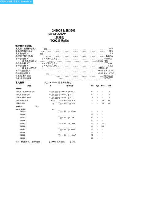
|常用三极管参数表下表是常用三极管的一些参数以及替换型号器件型号电压电流代换型号3DG9011 50V 2N4124 CS9011 JE9011 9011 50V LM9011 SS90119012 40V LM90129012(HH) 40V SS90129012LT1 40V A12983DG9013 40V CS9013 JE90139013 40V LM90139013(HH) 40V SS90139013LT1 40V C32653DG9014 50V CS9014 JE90149014 50V LM9014 SS90149014LT1 50V C16239015 50V LM9015 SS9015TEC9015 50V BC557 2N3906TEC9015A 50V BC557 2N3906TEC9015B 50V BC557 2N3906TEC9015C 50V BC557 2N39063DG9016 30V JE90169016 30V SS9016TEC9016 40V BF240 BF254 BF5948050 40V SS80508050LT1 40V KA3265ED8050 50V BC337SDT85501 60V 10A 3DK104CSDT85502 80V 10A 3DK104CSDT85503 100V 10A 3DK104DSDT85504 140V 10A 3DK104ESDT85505 170V 10A 3DK104FSDT85506 60V 10A 3DK104CSDT85507 80V 10A 3DK104CSDT85508 100V 10A 3DK104DSDT85509 140V 10A 3DK104EED8550 50V BC3378550 40V LM8550 SS85508550LT1 40V KA32652SA1015 50V BC177 BC204 BC212 BC213 BC251 BC257 BC307 BC512 BC557 CG1015 CG673 2SC1815 60V BC174 BC182 BC184 BC190 BC384 BC414 BC546 DG458 DG18152SC1815L 60V BC550 2SC2240 2S26742SC2675 2SC33782SC1815LT1 60V 9014LT12SC945 60V BC107 BC171 BC174 BC182 BC183 BC190 BC207 BC237 BC382 BC546 BC547 BC582 DG945 2N2220 2N2221 2N2222 3DG120B 3DG4312 MMBT3904 40V BCW72 3DG120CMMBT3906 40V BCW70 3DG120CMMBT2222 未知BCX19 3DG120CMMBT2222A 75V 3DK10CMMBT5401 160V 3CA3FMMBTA92 300V 3CG180HBC807 50V BC338 BC537 BC635 3DK14B BC807R 50V BCX17 BCX17R BCW68BCW68RBC807-W 50V BCX17 BCW68 2SB1219ABC817 50V BCX19 BCW65 BCX66BC817R 50V BCX19 BCX19R BCW65BCW65R BCX66 BCW66RBC817-W 50V BCX19 BCW65 BCW66 2SD1820 2SD1949BC846 80V BCV71 BCV72BC846R 80V BCV71 BCV71R BCV72 BCV72R BC846-W 80V BCV71 BCV72 BCV72RBC847 50V BCW71 BCW72 BCW81BC847R 50V BCW71 BCW71R BCW72 BCW72R BCW81 BCW81RBC847-W 50V BCW71 BCW72 BCW812SC4101 2SC4102BC848 30V BCW31 BCW32 BCW33 BCW71 BCW72 BCW81BC848R 30V BCW31 BCW31R BCW32 BCW32R BCW33 BCW33R BCW71 BCW71R BCW72 BCW72R BCW81 BCW81RBC848-W 30V BCW31 BCW32 BCW33 BCW71 BCW72 BCW81 2SC4101 2SC4102 2SC4117BC856 50V BCW89BC856R 80V BCW89 BCW89RBC856-W 80V BCW89 2SA1507 2SA1527BC857 50V BCW69 BCW70 BCW89BC857R 50V BCW69 BCW69R BCW70 BCW70R BCW89 BCW89RBC857-W 50V BCW69 BCW70 BCW892SA1507 2SA1527BC858 30V BCW29 BCW30 BCW69 BCW70 BCW89BC858R 30V BCW29 BCW29R BCW30 BCW30R BCW69 BCW69R BCW70 BCW70R BCW89 BCW89RBC858-W 30V BCW29 BCW30 BCW69 BCW70 BCW89 2SA1507 2SA15272SA733 60V BC177 BC204 BC212 BC213 BC251 BC257 BC307 BC513 BC557 3CG120C 3CG4312 MMUN2111 50V UN2111MUN2111 50V MMUN2111UN2111 50V FN1A4M DTA114EK RN24022SA1344MMUN2112 50V UN2112MUN2112 50V MMUN2112UN2112 50V FN1F4M DTA124EK RN24032SA1342MMUN2113 50V UN2113MUN2113 50V MMUN2113UN2113 50V FN1L4M DTA144EK RN24042SA1341MMUN2211 50V UN2211MUN2211 50V MMUN2211UN2211 50V DTC114EK FA1A4M RN14022SC3398MMUN2212 50V UN2212MUN2212 50V MMUN2212UN2212 50V DTC124EK FA1F4M RN14032SC3396MMUN2213 50V UN2213MUN2213 50V MMUN2213UN2213 50V DTC144EK FA1L4M RN14042SC33952SC3356 20V 2SC3513 2SC3606 2SC38292SC3838K 30V BF517 BF799 2SC3015 2SC3016彩显中易损大功率三极管主要参数表型号功率(W) 反压(V) 电流(A) 功能BU208A 50 1500 5 电源开关管BU508A 75 1500 8 电源开关管BU2508AF 45 1500 8 行管*BU2508DF 125 1500 8 行管*BU2508D 125 1500 8 行管BU2520AF 45 1500 10 行管BU2520AX 45 1500 10 行管* BU2520DF 125 1500 10 行管BU2522AF 45 1500 10 行管* BU2522DF 80 1500 10 行管* BU2525DF 45 800 12 行管BUH515 60 1500 8 行管C1520 10 250 视放C1566 250 视放C1573 250 视放C1875 50 1500 电源开关管C3153 100 900 6 电源开关管C3026 50 1700 5 行管C3457 50 1100 3 电源开关管C3459 90 1100 电源开关管C3460 100 1100 6 电源开关管C3461 140 1100 8 行管*C3683 50 1500 5 行管C3686 50 1400 8 行管C3687 150 1500 8 行管C3481 120 1500 5 电源开关管C3688 150 1500 10 行管*C3883 50 1500 5 行管C3885 50 1400 7 行管C3886 50 1400 8 行管C3887 80 1400 7 行管C3888 80 1400 80 行管C3889 80 1400 80 行管*C3891 50 1400 6 行管*C3892 50 1400 7 行管*C3893 50 1400 8 行管C3895 60W 1400V 7A 行管C3896 70 1400 8 行管*C3897 180 1500 12 行管C3897 250 1500 25 行管C3998 250 1500 25 行管*C4122 60 1500 6 行管*C4124 70 1500 8 行管*C4125 70 1500 10 行管C4237 150 800 10 行管*C4269 60 1500 7 行管*C4293 50 1500 5 行管*C4294 50 1500 6 行管*C4589 50 1500 10 行管*C4742 50 1500 6 行管*C4744 50 1500 6 行管C4747 50 1500 10 行管*C4769 60 1500 7 行管C4770 60 1500 7 行管C5048 50 1500 12 行管C5088 45 1500 8 行管C5129 50 1500 6 行管C5148 50 1500 8 行管C5250 50 1500 8 行管C5297 60 1500 8 行管C5299 60 1400 8 行管C5339 50 1500 7 行管C5418 120 1500 6 行管*D1396 50 1500 2 行管*D1398 50 1500 5 行管D1402 120 1500 5 电源开关管D1403 120 1500 6 电源开关管*D1426 80 1500 行管*D1427 80 1500 5 行管*D1428 80 1500 6 行管D1433 80 1500 7 行管D1434 80 1500 5 行管*D1554 40 1500 行管D1555 50 1500 5 电源开关管*D1878 60 1500 6 行管*D1879 60W 1500V 5A 行管*D1880 70 1500 8 行管*D1881 70 1500 10 行管D1886 70 1500 8 行管D1887 70 1500 10 行管*D2125 50 1500 5 行管*D870 50 1500 5 行管功率Pcm/W 反压BVCBO 电流ICM/A(*带阻尼)进口与国产显示器常用三极管代换表型号可代用型号用途价格2SA562 CG673B、2SB689 预视放2SA670 2SA1069、2SB513 电源调整管2SA673 2SA719、2SA697 帧激励2SA715 3CF3A、2SB529 场输出管2SA778A 3CG21C、CG75-1AB 开关电源误差放大2SA778AK C3CG21G、CG75-1A 开关电源误差放大2SA844D 3CG21C、CG75-1AB 视放2SA844E 3CG21G 视放2SA940 CD568B 场输出管2SA6395 2SA778、2SA858 行激励管2SB337 B337 电源调整管2SB407 3L780 电源调整管2SB548 3CF3B、2SA794 场输出管2SB566AK CD77-1A、3CF5A 电源调整管2SB556K CD77-1A、3CF5B 电源调整2SB621 3CG23B、2SB1035 电源推动管2SC458 3DG4A、2SC664 行振荡2SC536 3DG4A、2SC2320 电源推动管2SC562 G6738、B689 预视放2SC633 3DG6B、2SC1684 行振荡管2SC634 3DG12B 行振荡管2SC643A D2027、2SD818 行输出管2SC680A 3DD205B、2SC1025 场输出2SC681 3DD102B、2SC901 行输出2SC734 3DX200B、2SC2274 行振荡管2SC828 3DG56B、2SC3330 电源误差放大管2SC935 3DD102D、2SD320 电源调整管2SC8937 D2027、2SD818 行输出管2SC1034 2SD818、2SD299 行输出管2SC1162 FA433A、2SC2068 场输出枕形校正2SC1172 D2027、2SD820 行输出管2SC1209 3DG12A、2SD734 电源误差放大管2SC1213 3DG130A、2SC2120 电源误差放大管2SC1213A 3DG12B、2SC1247A 电源误差放大2SC1214 3DA151A、2SC2002 枕形校正2SC1308 D209、2SD820 行输出管2SC1318 3DG12A、2SC2274 行激励管2SC1364 3DX2038、2SC2320 行激励管2SC1505 DA1722B、2SC1757 行视放2SC1507 DA1722B、2SC1756、2SC1757 行激励管2SC1364 3DX2038、C23020 行激励管2SC1520 DA1722B、2SC2068 预视放2SC1566 3DA151D、2SC1514 视放2SC1573 3DA87C、2SC1762 视放2SC1672 3DD102B、2SC2433 电源调整管2SC1685 3DD180、2SC1570 脉冲开关2SC1819 3DA151D、2SC2425 视放2SC1890A 3DA878、2SC2363 视放2SC1905 3DA151D、2SD1163 视放2SC1942 D209、2SD1401 行输出管2SC2233 3DD12B、2SC2373 行输出2SD201 3DD102A、2SD125A 电源调整管2SD226 3DD207、2SD315 电源调整管2SD299 D2027、2SC1308 行输出管2SD350 D2027、2SD348 行输出管2SD380 D209、2SD348 行输出管2SD869 2SD993、2SD898B 行输出管C3150 C3151、C3152 开关管BU508A BU508D、C3893、C3895、C3897 开关管彩显中易损场效应管主要参数表型号功率Pcm/W 最大电流IDM/A D-S极间耐压价格2SK534 100W 5A 800V2SK538 100 3 9002SK557 100 12 5002SK560 100 15 5002SK566 78 3 800 2SK644 125 10 500 2SK719 120 5 900 2SK725 125 15 500 2SK727 125 5 900 2SK774 120 18 500 2SK785 150 20 500 2SK787 150 8 900 2SK788 150 13 500 2SK790 150 15 500 2SK872 150 6 900 2SK955 150 9 800 2SK956 150 9 800 2SK962 150 8 900 2SK1019 300 30 500 2SK1020 300 30 5002SK1081 125 7 800 2SK1082 125 6 800 2SK1117 100 6 600 2SK1118 45 6 600 2SK1119 100 4 1000 2SK1120 150 8 1000 2SK1171 240 5 1400 2SK1198 75 3 800 2SK1249 130 15 500 2SK1250 150 20 500 2SK1271 240 15 1400 2SK1280 150 18 500 2SK1281 120 4 700 2SK1341 100 5 900 2SK1342 100 8 9002SK1357 125 5 900 2SK1358 150 9 900 2SK1451 120 5 900 2SK1498 120 20 500 2SK1500 160 25 500 2SK1502 120 7 900 2SK1507 50 6 600 2SK1512 150 10 850 2SK1531 150 15 500 2SK1537 100 5 900 2SK1539 150 10 900 2SK1563 150 12 500 2SK1649 100 6 900 2SK1794 150 6 900 2SK2038 125 6 9002N7000 60BUZ385 125 6 500 GH30N60 180 30 600 GH30N100 250 30 1000 GH40N60 200 40 600H1245 120 12 450H13N50 150 13 500IBF834 100 3 500IPF440 125 8 500 IRT450 150 13 500 IRF350 150 13 500 IRF360 300 25 400IRF440 125 8 500 IRF451 150 13 450 IRF460 300 21 500IRF620 40 5 200IRF630 75 9 200 IRF634 75 250 IRF640 125 18 200 IRF730 75 400 IRF740 125 10 400 IRF820 50 500 IRF830 75 500 IRF834 100 5 500 IRF840 125 8 500 IRF841 125 8 450 IRF842 125 7 500 IRF9610 20 1 200 IRF9630 75 200 IRF9640 125 11 200 IRF450 150 13 500 IRFD113 1 80IRFD123 1 80FIRP150 180 41 100IRFP151 180 19 60IRFP240 150 31 200IRFP250 180 31 200IRFP251 180 33 150IRFP254 180 23 250IRFP350 180 16 400IRFP351 180 16 350IRFP360 250 23 400IRFP450 180 14 500IRFP452 180 12 500IRFP460 250 20 500IRFBC40 125 600IRF4P51 180 14 450 IXGH10N100 100 10 1000IXGH15N100 150 150 1000 IXGH20N60 150 20 600 IXTH50N30 150 50 300 IXTH50X20 250 50 200 IXTH67N10 200 67 100 LXTH24N50 250 24 500 LXTH30N20 180 30 200 LXTH30N30 180 30 300 LXTH30N50 300 30 500 LXTH40N30 250 40 300 LXTH50N10 150 50 100 LXTH50N20 150 50 200 LXTH67N70 200 67 100 LXTH75N10 200 75 100MTH8N50 120 8 500MTM6N80 120 6 800METH10N50 120 10 500 MTH12N50 120 12 500 MTH14N50 150 14 500 MTH20N20 120 20 200 MTH25N10 150 25 200 MTH30N10 120 30 100 MTH35N15 150 35 150 MTH40N10 150 40 100 MTH8N60 120 8 600 MTM10N20 75 10 200 MTM20N20 125 20 200 MTM25N10 100 25 100 MTM30N10 120 30 100 MTM40N10 150 40 100 MTM6N90 150 6 900 MTM8N50 100 8 500MTM8N90 150 8 900 MTP3N60 75 3 600 MTP3N100 75 3 1000 MTP4N60 50 4 600 MTP4N80 50 4 800 MTP5P25 75 5 250 MTP5N45 75 5 450 MTP5N50 75 5 500 MTP6N60 125 6 600 MTP6N60E 125 6 600 RFP50N05 132 50 50 RFP50N05L 110 50 50型号反压(V) 电流(A) 功率(W) β值阻尼D1175 1500 5 100 15 有D1279 1500 10 50 20 无D1391 1500 5 80 12 有D1398 1500 5 50 12 有D1403 1500 6 120 20 无D1426 1500 80 有D1427 1500 5 80 有D1428 1500 6 80 12 有D1429 1500 80 20 有D1431 1500 5 80 无D1432 1500 6 80 20 有D1433 1500 7 80 20 有D1439 1500 3 50 有D1497 1500 6 50 15 有D1545 1500 5 50 20 无D1547 1500 7 50 20 无D1554 1500 40 有D1555 1500 5 50 有D1556 1500 6 50 12 有D1651 1500 5 60 有D1652 1500 6 60 15 有D1710 1500 6 100 20 无D1878 1500 6 50 15 有D1879 1500 6 60 15 有D1880 1500 8 70 有D1881 1500 10 70 有D1884 1500 5 60 无D1885 1500 6 60 无D1910 1500 3 40 20 有D1959 1400 10 50 20 无D2125 1500 5 50 12 有D2251 1500 7 60 有D2252 1500 7 60 无D2253 1700 6 50 有D2334 1500 5 80 15 无D2335 1500 7 100 15 无型号P/N 参数备注及用途型号P/N 参数A940 P 4MHz TO-220 D1271 N 150V7A40WC2073 N 4MHz TO-220 D1273A N 100V3A40WA1304C3296 4MHz D1275A N 80V2A35WB647D667 140MHz D1266 N 80V3A35WD669 140MHz D1264A N 200V2A30WB834D880 60V3A30W TO-220 D1309 N 150V8A40WB546D401 200V2A20W 5MHz D1365 N 800V3A40WB772D882 40V3A10W 80MHz D1415 N 100V7A40W56105609 100MHz D1499 N 100V5A40WB1185D1762 60V3A25W 70MHz D2025 N 100V8A30WB1186D1763 50MHz TIP102 N 100V8A80WTIP42CTIP41C 100V5A65W >3MHz TOP202 TOP222TIP122 100V5A65W >1000 TOP223 TOP224封装MJE13003 NC2335 N 400V7A40W MJE13005 N 400V4A75WC3148 N 800V3A40W MJE13007 N 400V8A80WC3309 N 400V2A20W MJE13009 N 400V12A100WC3310 N 400V5A30WC4004 N 800V1A30W C388A NC3039 N 400V7A50W C458 N N 200V4A40W C536 N N C945 N N 100V3A25W 15MHz >500 C752 N N 400V8A45W<300/140nS C1047 NC5027 N C1162 NC5249 N C1213 N N 60V3A30W 8MHz C1360 ND1138 N C1383 N 30V1A1WD1071 N 450V6A40W >500 C1473 N 参数备注及用途型号参数备注及用途N 1500/ 行TOS BUW11A N 1000/450V5A100W 电源AF=50WPHIN 1500/600V5A50W 行TOS BUW12A N 1000/450V10A125W电源AF=50W PHIN 1500/600V6A50W 行TOS BUW13A N 1000/450V15A175W电源AF=50W PHIN 1700/600V6A50W 行TOS BU2508AF N 1500/700V8A50W电源PHIN 1500/ 行TOS BU2508DF N 1500/700V8A50W 行PHIN 1500/600V5A80W 行TOS BU2508AX N 1500/700V8A50W电源PHIN 1500/600V7A80W 电源TOS BU2508DX N 1500/700V8A50W行PHIN 1500/600V7A80W 行TOS BU2520AF N 1500/800V10A50W电源PHIN 1500/600V6A80W 行TOS BU2520DF N 1500/800V10A50W行PHIN 1500V5A50W 电源/行TOS BU2520AX N 1500/800V10A50W电源/行PHIN 1500V7A50W 电源/行TOS BU2520DX N1500/800V10A60W 行PHIN 1400V10A50W 电源/行TOS BU2522AX N1500/800V10A60W 电源/行PHIN 1500/600V6A50W 电源TOS BU2523AX N1500/800V10A60W 电源/行PHIN 1500/600V6A50W 行TOS BU2527AX N 1500/800V12A60W电源/行PHIN 1500/600V10A50W 电源TOS BU2527DX N1500/800V12A60W 行PHIN 1500/600V8A50W 电源TOS C4236 N 1200/800V6A100W电源SHIN 1500/600V8A50W 行TOS C4237 N 1200/800V10A50W 电源SHIN 1700/600V8A50W 行TOS D1541 N 1500V3A50W 行MATN 1500/600V7A50W 行TOS C4111 N 1500/700V10A150W 电源MATN 1500/600V8A50W 行TOS MN650 N 1500/600V5A80W 电源SAKN 1500/600V10A50W 电源TOS C4058 N 600/450V10A100W电源SHIN 1500/600V8A50W 电源TOS D2333 N 1500/600V5A80W 行MATN 1400/600V12A200W 电源TOS D2334 N 1500/600V5A80W电源MATN 900/800V5A100W 电源TOS D2335 N 1500/600V7A100W行MATN 1500V8A125W 电源TOS C4706 N 900/600V14A130W 电源SAKN 1500/700V8A60W 电源ST BUH715N N 1500/700V10A60W电源STN 1500/700V8A60W 行ST C3927 N 900/600V10A120W 电源SAKN 1500/700V10A57W 电源ST C3679 N 900/800V5A100W 电源SAKN 1500/700V7A50W 行ST C5287 N 900/550V5A80W 电源SAK型号P/N 参数备注及用途型号P/N 参数D2445 N 1500/800V6A50W K30A 50VIdss><5VC4745 N 1500/800V6A50W 电源HIT K117 50VIdss><10VC4746 N 1500/800V8A50W 电源HIT K118 50VIdss><C5250 N 1500V8A50W 行HIT K304 30VIdss><4VC5207A N 1500/800V10A50W 电源HIT K1117 600V6A100W D2300 N 1500V5A50W 行HIT K1118 600V6A45WC4297 N 500/400V12A75W 电源SAK K1119 1000V4A100W C4927 N 1500V8A50W 行HIT K2141 600V+/-6A35WD1959 N 1400/650V10A50W 电源HIT K1507 600V9A50W C4589 N 1500/800V10A50W 电源HIT K1995 900V+/-3A35W C4877 N 1500V8A50W 行HIT K1445 450V5A30WKSD5072 N 1500/800V5A60W 行SAM K2056 800V4A40WKSD5076 N 1500/800V5A60W 行SAM IRFBC30KSC5802 IRFBC40RKSC5803 N 1500/800V7A50W 行SAM IRFBC60KSC5386 N 1500/800V7A50W 行SAM IRF530N 100V15A80WKSC5088 N 1500/800V8A50W 电源SAM IRF9530N100V13A75WKSD5702 N 1500V6A70W 行SAM IRF540N 100V27A94W KSD5703 IRF9540N 100V19A94W BUS13A N 1000/450V15A175W 电源VAL TO-3 IRF610 BUS14A N 1000/450V30A250W 电源VAL TO-3 IRF9610 BUV48A N 1000/450V15A150W 电源ST IRF620 200V5A40W C3552 N 1100/800V12A150W 电源SAK IRF9620 200V5A40W C5386 N 1500/600V8A50W 电源TOS IRF630 200V9A75W C4119 N 1500/800V15A250W 达林顿+阻尼IRF9630系列晶振455KHz-503KHz IRF640 200V18A125WIRF9640 200V11A125W二极管开关管快恢复整流管IRF730 稳压管阻尼管IRF740 400V10A125W 型号参数特性型号参数BC327 P 100MHz BTA08 8A双向BC337 N 100MHz BTA12 12A双向BC328 P 100MHz BTA20 20A双向BC338 N 100MHz BTA26 26A双向BC369 P 65MHz BTA41 41A双向BC546 N 300MHz BTA16 16A双向BC547 N 300MHz 2P4M 3A单向BC558 N 150MHz CR3AM 3A单向BC556 P 150MHz TLC336 3A双向BC557 P 150MHz BCR3AM 3A双向9011 N 150MHz FD312 彩电用9012 P FD315 彩电用9013 N PH2369 彩电用9014 N 150MHz 1W稳压管9015 P 100MHz 1N4728A9016 N 620MHz9018 N 700MHz 1N4732A8050 N 100MHz8550 P 100MHz 1N4736A2N5551 N 100MHz 1N4738A2N5401 P 100MHz 1N4740A 10V可控硅1N4742A 12V1A单向BT169 100-6 100-8 FOR1B FOR3G 1N4744A 15V 1A双向97A6 94A4 97A4 1N4746A 18V BT136 6A双向中间引线通散热片1N4748A 22VBT137 8A双向中间引线通散热片1N4750A 27V BT138 10A 双向中间引线通散热片1N4752A 33V BT139 12A双向中间引线通散热片1N4756A 47VBTA06 6A双向中间线不通散热片1N4764A 100V 型号参数特性型号参数D820 N 1500/600V5A80W 电源D1047 N 160V12A100W D869 N 1500/ 行B817 P 160V12A100WD850 N 1500/700V3A65W 电源D1559 N 100V20A100W D870 N 1500/600V5A50W 行B1079 P 100V20A100WD905 N 1400/650W8A50W 电源D2256 N 120V25A120W D871 N 1500/600V6A50W 行B1494 P 120V25A120WD1204 N 500/400V15A100W 电源D718 N 120V8A80WD898 N 行B688 P 120V8A80WD1279 N 1400/700V10A50W 电源D1435 N 100V15A100W D951 N 1500V3A65W 行B1031 P 100V15A100WC1942 N 1500/800V3A50W 电源带阻三极管D1173 N 1500V5A70W 行RN1201 RN1202 C2027 N 1500/800V5A50W 电源RN1206 RN2201D1175 N 1500V5A100W 行RN1001 RN1001大功率功放管DTA114 DTA144C3280 N 160V12A120W HiFi TOS DTC144A1301 P 160V12A120W HiFi TOD 光藕及三端C3281 N 200V15A150W HiFi TOS 521-1 621-1A1302 P 200V15A150W HiFi TOS 631 632C5200 N 230V15A150W HiFi TOS 4N35 CNX62AA1943 P 230V15A150W HiFi TOS PC113 PC117D2155 N 180V15A150W HiFi TOS SE090 SE110B1429 P 180V15A150W HiFi TOS SE120 SE125C5198 N 140V10A100W HiFi TOS SE135 SE140A1941 P 140V10A100W HiFi TOS 78(L)06 78(L)08 C5196 N 120V6A60W HiFi TOS 78(L)12 78(L)15A1939 P 120V6A60W HiFi TOS 78(L)24 79(L)05C3182 N 140V10A100W HiFi TOS 79(L)08 79(L)09 A1265 P 140V10A100W HiFi TOS 79(L)15 79(L)18型号P/N 参数备注及用途型号P/N 参数C1514 N 80MHz Vid-L HIT C2481 NC1507 N 80MHz Vid-L NIP C2611 N N 100MHz Vid TOSC2330 NC1573 N 80MHz NF Vid MAT C2331 NC1627 N Uni TOS C2655 NC1687 N NF/ZF MAT C2688 NC1756 N >50MHz SAY C2653 NC1740 N 180MHz Uni TOS C2785 N N >80MHz Uni TOS C2878 N N 45V1A5W 200MHzNF/S-LMAT C3355 N N UHFHIT C3417 NC1959 N 300MHz Uni TOS C3419 NC2001 N 70MHz Uni NIP C3420 N 50V5A10WC2068 N 95MHz Vid TOS C3807 N 30V2A15WC2120 N 120MHz Uni TOS C3789 NC2026 N 2GHz UHF NIP C3198 N N 150MHz Uni TOYC4075 NC2229 N 120MHz Vid TOS C4544 NC2230 N >50MHz Vid TOS D400 N 25V1A1W C2271 N Vid TOS D471 N 30V1A1WC2258 N Vid MAT D965 NC2240 N 100MHz TOS D966 N 40V5A1W C2482 N Vid TOS D612 N 35V2A10WC2236 N Uni TOS D789 NC2371 N Vid NIP D1640 NC2383 N NF/VA TOS D415 NC2482 N Vid TOS C3946 NC2594 N 40V5A10W 150MHz D1406 N 60V3A30W C2500 N 150MHz Uni TOS。

nt90hce12cb继电器原理
NT90HCE12CB继电器是一种电子控制器件,其工作原理是利用电磁感应原理控制电路中的触点开关,从而实现电路的自动控制。
具体来说,当继电器线圈通电时,会产生磁场,使铁芯磁化并吸引衔铁,从而带动触点开关动作。
当线圈断电时,磁场消失,衔铁返回原位,触点开关也相应断开。
通过控制继电器线圈的通电和断电,可以实现电路的自动控制和保护。
此外,NT90HCE12CB继电器还有其他一些工作原理,如时间延迟、温度控制等,具体实现方式会因继电器型号和规格的不同而有所差异。


MC9S12ZVM-Family Reference Manual HCS12MicrocontrollersTo provide the most up-to-date information, the document revision on the Internet is the most current. A printed copy may be an earlier revision. To verify you have the latest information available, refer to :.This document contains information for all constituent modules, with the exception of the S12Z CPU. For S12ZCPU information please refer to the CPU S12Z Reference Manual.S12ZVM32 and S12ZVM16 specific information is preliminary until these devices are qualified.The following revision history table summarizes changes contained in this document. The individual module sections contain revision history tables with more detailed information.Freescale Semiconductor reserves the right to make changes without further notice to any products herein. Freescale Semiconductor makes no warranty,representation or guarantee regarding the suitability of its products for any particular purpose, nor does Freescale Semiconductor assume any liability arising out of the application or use of any product or circuit, and specifically disclaims any and all liability, including without limitation consequential or incidental damages. “Typical” parameters that may be provided in Freescale Semiconductor data sheets and/or specifications can and do vary in different applications and actual performance may vary over time. All operating parameters, including “Typicals”, must be validated for each customer application by customer’s technical experts. Freescale Semiconductor does not convey any license under its patent rights nor the rights of others. Freescale Semiconductor products are not designed, intended, or authorized for use as components in systems intended for surgical implant into the body, or other applications intended to support or sustain life, or for any other application in which the failure of the Freescale Semiconductor product could create a situation where personal injury or death may occur. Should Buyer purchase or Table 0-1. Revision History DateRevision Description 12 Dec 2013 1.2 Replaced generic 8-channel TIM section with specific 4-channel TIM sectionTextual enhancements and corrections throughoutUpdated electrical parameter section and added parameters for temperataures up to 175°C- Added Table A-5- Merged Table A-8 and A-9 into Table A-9. Values updated. .- Table A-15. Parameter #2. max changed from 800uA to 1050uA- Table A-15. Inserted new C class parameter ISUPS at 85C. typ. 80uA- Appendices B,D and E. Updated parameter values based on characterization results.- Appendix C. Added parameter values for range above T=150°C- Table F-3. Merged rows 2a and 2b. Merged rows 6a and 6b.- Appendix G. Merged tables G-1 and G-2.- Tables H-1 and H-2 values updated.20 JAN 2014 1.3Updated Stop mode description for BDC enabled caseRemoved false reference to modified clock monitor assert frequencyUpdated electricals for 175°C Grade0- Removed temperature range disclaimer from electrical parameter spec.footer- Added sentence above table A-3- Table D-1. LINPHY parameters 12a and 12b replaced by 12a, 12b and 12c-- Table D-2. LINPHY wake up pulse over whole temperature range- Table E-1. FET gate charge spec. updated22 MAY2014 1.4Updated family derivative table for S12ZVML32, S12ZVM32 and S12ZVM16 devicesAdded 64KB, 32KB and 16KB derivative information to flash module chapterAdded pin routing options for S12ZVM32 and S12ZVM16 devicesAdded HV Phy information for the S12ZVM32 and S12ZVM16 derivativesUpdated Part ID assignment table and ordering information for S12ZVM32 and S12ZVM16Corrected PLL VCO maximum frequency specificationChanged V LVLSA maximum from 7V to 6.9VAdded electrical parameter for HD division ratio through the phase multiplexerCorrected preferred VRL reference from VRL_1 to VRL_0Included NVM timing parameters for the S12ZVM32 and S12ZVM16 devicesAdded GDU S12ZVM32 and S12ZVM16 specific differences and electrical specificationsAdded references to f WSTAT Added VDDX short circuit fall back current and temperature/input dependency specs.Chapter1Device Overview MC9S12ZVM-Family1.1Introduction . . . . . . . . . . . . . . . . . . . . . . . . . . . . . . . . . . . . . . . . . . . . . . . . . . . . . . . . . . . . . . . . . . 17 1.2Features . . . . . . . . . . . . . . . . . . . . . . . . . . . . . . . . . . . . . . . . . . . . . . . . . . . . . . . . . . . . . . . . . . . . . 181.2.1MC9S12ZVM-Family Member Comparison . . . . . . . . . . . . . . . . . . . . . . . . . . . . . . . . . 181.2.2Functional Differences Between N06E and 0N95G Masksets . . . . . . . . . . . . . . . . . . . . 191.2.3Functional Differences Between 1N95G and 0N95G Masksets . . . . . . . . . . . . . . . . . . . 20 1.3Chip-Level Features . . . . . . . . . . . . . . . . . . . . . . . . . . . . . . . . . . . . . . . . . . . . . . . . . . . . . . . . . . . . 20 1.4Module Features . . . . . . . . . . . . . . . . . . . . . . . . . . . . . . . . . . . . . . . . . . . . . . . . . . . . . . . . . . . . . . . 211.4.1S12Z Central Processor Unit (CPU) . . . . . . . . . . . . . . . . . . . . . . . . . . . . . . . . . . . . . . . . 211.4.2Embedded Memory . . . . . . . . . . . . . . . . . . . . . . . . . . . . . . . . . . . . . . . . . . . . . . . . . . . . . 221.4.3Clocks, Reset & Power Management Unit (CPMU) . . . . . . . . . . . . . . . . . . . . . . . . . . . . 231.4.4Main External Oscillator (XOSCLCP) . . . . . . . . . . . . . . . . . . . . . . . . . . . . . . . . . . . . . . 241.4.5Timer (TIM) . . . . . . . . . . . . . . . . . . . . . . . . . . . . . . . . . . . . . . . . . . . . . . . . . . . . . . . . . . . 241.4.6Pulse width Modulator with Fault protection (PMF) . . . . . . . . . . . . . . . . . . . . . . . . . . . . 241.4.7Programmable Trigger Unit (PTU) . . . . . . . . . . . . . . . . . . . . . . . . . . . . . . . . . . . . . . . . . 241.4.8LIN physical layer transceiver . . . . . . . . . . . . . . . . . . . . . . . . . . . . . . . . . . . . . . . . . . . . . 251.4.9Serial Communication Interface Module (SCI) . . . . . . . . . . . . . . . . . . . . . . . . . . . . . . . . 251.4.10Multi-Scalable Controller Area Network (MSCAN) . . . . . . . . . . . . . . . . . . . . . . . . . . . . 251.4.11Serial Peripheral Interface Module (SPI) . . . . . . . . . . . . . . . . . . . . . . . . . . . . . . . . . . . . . 261.4.12Analog-to-Digital Converter Module (ADC) . . . . . . . . . . . . . . . . . . . . . . . . . . . . . . . . . 261.4.13Supply V oltage Sensor (BATS) . . . . . . . . . . . . . . . . . . . . . . . . . . . . . . . . . . . . . . . . . . . . 261.4.14On-Chip V oltage Regulator system (VREG) . . . . . . . . . . . . . . . . . . . . . . . . . . . . . . . . . . 261.4.15Gate Drive Unit (GDU) . . . . . . . . . . . . . . . . . . . . . . . . . . . . . . . . . . . . . . . . . . . . . . . . . . 271.4.16Current Sense . . . . . . . . . . . . . . . . . . . . . . . . . . . . . . . . . . . . . . . . . . . . . . . . . . . . . . . . . . 271.4.17High V oltage Physical Interface (S12ZVM32, S12ZVM16) . . . . . . . . . . . . . . . . . . . . . . 27 1.5Block Diagram . . . . . . . . . . . . . . . . . . . . . . . . . . . . . . . . . . . . . . . . . . . . . . . . . . . . . . . . . . . . . . . . 28 1.6Device Memory Map . . . . . . . . . . . . . . . . . . . . . . . . . . . . . . . . . . . . . . . . . . . . . . . . . . . . . . . . . . . 291.6.1Flash Module . . . . . . . . . . . . . . . . . . . . . . . . . . . . . . . . . . . . . . . . . . . . . . . . . . . . . . . . . . 301.6.2Part ID Assignments . . . . . . . . . . . . . . . . . . . . . . . . . . . . . . . . . . . . . . . . . . . . . . . . . . . . 32 1.7Signal Description and Device Pinouts . . . . . . . . . . . . . . . . . . . . . . . . . . . . . . . . . . . . . . . . . . . . . 321.7.1Pin Assignment Overview . . . . . . . . . . . . . . . . . . . . . . . . . . . . . . . . . . . . . . . . . . . . . . . . 321.7.2Detailed External Signal Descriptions . . . . . . . . . . . . . . . . . . . . . . . . . . . . . . . . . . . . . . . 331.7.3Power Supply Pins . . . . . . . . . . . . . . . . . . . . . . . . . . . . . . . . . . . . . . . . . . . . . . . . . . . . . . 391.7.4Package and Pinouts . . . . . . . . . . . . . . . . . . . . . . . . . . . . . . . . . . . . . . . . . . . . . . . . . . . . 40 1.8Internal Signal Mapping . . . . . . . . . . . . . . . . . . . . . . . . . . . . . . . . . . . . . . . . . . . . . . . . . . . . . . . . . 461.8.1ADC Connectivity . . . . . . . . . . . . . . . . . . . . . . . . . . . . . . . . . . . . . . . . . . . . . . . . . . . . . . 471.8.2Motor Control Loop Signals . . . . . . . . . . . . . . . . . . . . . . . . . . . . . . . . . . . . . . . . . . . . . . 481.8.3Device Level PMF Connectivity . . . . . . . . . . . . . . . . . . . . . . . . . . . . . . . . . . . . . . . . . . . 481.8.4BDC Clock Source Connectivity . . . . . . . . . . . . . . . . . . . . . . . . . . . . . . . . . . . . . . . . . . . 481.8.5LINPHY Connectivity . . . . . . . . . . . . . . . . . . . . . . . . . . . . . . . . . . . . . . . . . . . . . . . . . . . 481.8.6HVPHY Connectivity . . . . . . . . . . . . . . . . . . . . . . . . . . . . . . . . . . . . . . . . . . . . . . . . . . . 481.8.7FTMRZ Connectivity . . . . . . . . . . . . . . . . . . . . . . . . . . . . . . . . . . . . . . . . . . . . . . . . . . . 491.8.8CPMU Connectivity . . . . . . . . . . . . . . . . . . . . . . . . . . . . . . . . . . . . . . . . . . . . . . . . . . . . 49 1.9Modes of Operation . . . . . . . . . . . . . . . . . . . . . . . . . . . . . . . . . . . . . . . . . . . . . . . . . . . . . . . . . . . . 491.9.1Chip Configuration Modes . . . . . . . . . . . . . . . . . . . . . . . . . . . . . . . . . . . . . . . . . . . . . . . 491.9.2Debugging Modes . . . . . . . . . . . . . . . . . . . . . . . . . . . . . . . . . . . . . . . . . . . . . . . . . . . . . . 501.9.3Low Power Modes . . . . . . . . . . . . . . . . . . . . . . . . . . . . . . . . . . . . . . . . . . . . . . . . . . . . . . 50 1.10Security . . . . . . . . . . . . . . . . . . . . . . . . . . . . . . . . . . . . . . . . . . . . . . . . . . . . . . . . . . . . . . . . . . . . . . 511.10.1Features . . . . . . . . . . . . . . . . . . . . . . . . . . . . . . . . . . . . . . . . . . . . . . . . . . . . . . . . . . . . . . 511.10.2Securing the Microcontroller . . . . . . . . . . . . . . . . . . . . . . . . . . . . . . . . . . . . . . . . . . . . . . 511.10.3Operation of the Secured Microcontroller . . . . . . . . . . . . . . . . . . . . . . . . . . . . . . . . . . . . 521.10.4Unsecuring the Microcontroller . . . . . . . . . . . . . . . . . . . . . . . . . . . . . . . . . . . . . . . . . . . . 521.10.5Reprogramming the Security Bits . . . . . . . . . . . . . . . . . . . . . . . . . . . . . . . . . . . . . . . . . . 531.10.6Complete Memory Erase . . . . . . . . . . . . . . . . . . . . . . . . . . . . . . . . . . . . . . . . . . . . . . . . . 53 1.11Resets and Interrupts . . . . . . . . . . . . . . . . . . . . . . . . . . . . . . . . . . . . . . . . . . . . . . . . . . . . . . . . . . . 541.11.1Resets . . . . . . . . . . . . . . . . . . . . . . . . . . . . . . . . . . . . . . . . . . . . . . . . . . . . . . . . . . . . . . . . 541.11.2Interrupt Vectors . . . . . . . . . . . . . . . . . . . . . . . . . . . . . . . . . . . . . . . . . . . . . . . . . . . . . . . 541.11.3Effects of Reset . . . . . . . . . . . . . . . . . . . . . . . . . . . . . . . . . . . . . . . . . . . . . . . . . . . . . . . . 57 1.12Module device level dependencies . . . . . . . . . . . . . . . . . . . . . . . . . . . . . . . . . . . . . . . . . . . . . . . . . 581.12.1CPMU COP Configuration . . . . . . . . . . . . . . . . . . . . . . . . . . . . . . . . . . . . . . . . . . . . . . . 581.12.2CPMU High Temperature Trimming . . . . . . . . . . . . . . . . . . . . . . . . . . . . . . . . . . . . . . . . 581.12.3Flash IFR Mapping . . . . . . . . . . . . . . . . . . . . . . . . . . . . . . . . . . . . . . . . . . . . . . . . . . . . . 58 1.13Application Information . . . . . . . . . . . . . . . . . . . . . . . . . . . . . . . . . . . . . . . . . . . . . . . . . . . . . . . . . 591.13.1ADC Calibration . . . . . . . . . . . . . . . . . . . . . . . . . . . . . . . . . . . . . . . . . . . . . . . . . . . . . . . 591.13.2SCI Baud Rate Detection . . . . . . . . . . . . . . . . . . . . . . . . . . . . . . . . . . . . . . . . . . . . . . . . . 591.13.3Motor Control Application Overview . . . . . . . . . . . . . . . . . . . . . . . . . . . . . . . . . . . . . . . 601.13.4BDCM Complementary Mode Operation . . . . . . . . . . . . . . . . . . . . . . . . . . . . . . . . . . . . 681.13.5BLDC Six-Step Commutation . . . . . . . . . . . . . . . . . . . . . . . . . . . . . . . . . . . . . . . . . . . . . 721.13.6PMSM Control . . . . . . . . . . . . . . . . . . . . . . . . . . . . . . . . . . . . . . . . . . . . . . . . . . . . . . . . . 741.13.7Power Domain Considerations . . . . . . . . . . . . . . . . . . . . . . . . . . . . . . . . . . . . . . . . . . . . 78Chapter2Port Integration Module (S12ZVMPIMV2)2.1Introduction . . . . . . . . . . . . . . . . . . . . . . . . . . . . . . . . . . . . . . . . . . . . . . . . . . . . . . . . . . . . . . . . . . 832.1.1Overview . . . . . . . . . . . . . . . . . . . . . . . . . . . . . . . . . . . . . . . . . . . . . . . . . . . . . . . . . . . . . 832.1.2Features . . . . . . . . . . . . . . . . . . . . . . . . . . . . . . . . . . . . . . . . . . . . . . . . . . . . . . . . . . . . . . 84 2.2External Signal Description . . . . . . . . . . . . . . . . . . . . . . . . . . . . . . . . . . . . . . . . . . . . . . . . . . . . . . 84 2.3Memory Map and Register Definition . . . . . . . . . . . . . . . . . . . . . . . . . . . . . . . . . . . . . . . . . . . . . . 882.3.1Register Map . . . . . . . . . . . . . . . . . . . . . . . . . . . . . . . . . . . . . . . . . . . . . . . . . . . . . . . . . . 892.3.2PIM Registers 0x0200-0x020F . . . . . . . . . . . . . . . . . . . . . . . . . . . . . . . . . . . . . . . . . . . . 932.3.3PIM Generic Registers . . . . . . . . . . . . . . . . . . . . . . . . . . . . . . . . . . . . . . . . . . . . . . . . . . 1012.3.4PIM Generic Register Exceptions . . . . . . . . . . . . . . . . . . . . . . . . . . . . . . . . . . . . . . . . . 109 2.4Functional Description . . . . . . . . . . . . . . . . . . . . . . . . . . . . . . . . . . . . . . . . . . . . . . . . . . . . . . . . . 1102.4.1General . . . . . . . . . . . . . . . . . . . . . . . . . . . . . . . . . . . . . . . . . . . . . . . . . . . . . . . . . . . . . . 1102.4.2Registers . . . . . . . . . . . . . . . . . . . . . . . . . . . . . . . . . . . . . . . . . . . . . . . . . . . . . . . . . . . . . 1112.4.3Pin I/O Control . . . . . . . . . . . . . . . . . . . . . . . . . . . . . . . . . . . . . . . . . . . . . . . . . . . . . . . . 1122.4.4Interrupts . . . . . . . . . . . . . . . . . . . . . . . . . . . . . . . . . . . . . . . . . . . . . . . . . . . . . . . . . . . . 1132.4.5Pin interrupts and Key-Wakeup (KWU) . . . . . . . . . . . . . . . . . . . . . . . . . . . . . . . . . . . . 1142.4.6Over-Current Interrupt . . . . . . . . . . . . . . . . . . . . . . . . . . . . . . . . . . . . . . . . . . . . . . . . . . 1152.5Initialization and Application Information . . . . . . . . . . . . . . . . . . . . . . . . . . . . . . . . . . . . . . . . . . 1152.5.1Port Data and Data Direction Register writes . . . . . . . . . . . . . . . . . . . . . . . . . . . . . . . . 1152.5.2Over-Current Protection on EVDD1 . . . . . . . . . . . . . . . . . . . . . . . . . . . . . . . . . . . . . . . 115Chapter3Memory Mapping Control (S12ZMMCV1)3.1Introduction . . . . . . . . . . . . . . . . . . . . . . . . . . . . . . . . . . . . . . . . . . . . . . . . . . . . . . . . . . . . . . . . . 1173.1.1Glossary . . . . . . . . . . . . . . . . . . . . . . . . . . . . . . . . . . . . . . . . . . . . . . . . . . . . . . . . . . . . . 1183.1.2Overview . . . . . . . . . . . . . . . . . . . . . . . . . . . . . . . . . . . . . . . . . . . . . . . . . . . . . . . . . . . . 1183.1.3Features . . . . . . . . . . . . . . . . . . . . . . . . . . . . . . . . . . . . . . . . . . . . . . . . . . . . . . . . . . . . . 1183.1.4Modes of Operation . . . . . . . . . . . . . . . . . . . . . . . . . . . . . . . . . . . . . . . . . . . . . . . . . . . . 1193.1.5Block Diagram . . . . . . . . . . . . . . . . . . . . . . . . . . . . . . . . . . . . . . . . . . . . . . . . . . . . . . . . 119 3.2External Signal Description . . . . . . . . . . . . . . . . . . . . . . . . . . . . . . . . . . . . . . . . . . . . . . . . . . . . . 119 3.3Memory Map and Register Definition . . . . . . . . . . . . . . . . . . . . . . . . . . . . . . . . . . . . . . . . . . . . . 1203.3.1Memory Map . . . . . . . . . . . . . . . . . . . . . . . . . . . . . . . . . . . . . . . . . . . . . . . . . . . . . . . . . 1203.3.2Register Descriptions . . . . . . . . . . . . . . . . . . . . . . . . . . . . . . . . . . . . . . . . . . . . . . . . . . . 120 3.4Functional Description . . . . . . . . . . . . . . . . . . . . . . . . . . . . . . . . . . . . . . . . . . . . . . . . . . . . . . . . . 1253.4.1Global Memory Map . . . . . . . . . . . . . . . . . . . . . . . . . . . . . . . . . . . . . . . . . . . . . . . . . . . 1253.4.2Illegal Accesses . . . . . . . . . . . . . . . . . . . . . . . . . . . . . . . . . . . . . . . . . . . . . . . . . . . . . . . 1273.4.3Uncorrectable ECC Faults . . . . . . . . . . . . . . . . . . . . . . . . . . . . . . . . . . . . . . . . . . . . . . . 128Chapter4Interrupt (S12ZINTV0)4.1Introduction . . . . . . . . . . . . . . . . . . . . . . . . . . . . . . . . . . . . . . . . . . . . . . . . . . . . . . . . . . . . . . . . . 1294.1.1Glossary . . . . . . . . . . . . . . . . . . . . . . . . . . . . . . . . . . . . . . . . . . . . . . . . . . . . . . . . . . . . . 1304.1.2Features . . . . . . . . . . . . . . . . . . . . . . . . . . . . . . . . . . . . . . . . . . . . . . . . . . . . . . . . . . . . . 1304.1.3Modes of Operation . . . . . . . . . . . . . . . . . . . . . . . . . . . . . . . . . . . . . . . . . . . . . . . . . . . . 1314.1.4Block Diagram . . . . . . . . . . . . . . . . . . . . . . . . . . . . . . . . . . . . . . . . . . . . . . . . . . . . . . . . 131 4.2External Signal Description . . . . . . . . . . . . . . . . . . . . . . . . . . . . . . . . . . . . . . . . . . . . . . . . . . . . . 132 4.3Memory Map and Register Definition . . . . . . . . . . . . . . . . . . . . . . . . . . . . . . . . . . . . . . . . . . . . . 1324.3.1Module Memory Map . . . . . . . . . . . . . . . . . . . . . . . . . . . . . . . . . . . . . . . . . . . . . . . . . . 1324.3.2Register Descriptions . . . . . . . . . . . . . . . . . . . . . . . . . . . . . . . . . . . . . . . . . . . . . . . . . . . 133 4.4Functional Description . . . . . . . . . . . . . . . . . . . . . . . . . . . . . . . . . . . . . . . . . . . . . . . . . . . . . . . . . 1384.4.1S12Z Exception Requests . . . . . . . . . . . . . . . . . . . . . . . . . . . . . . . . . . . . . . . . . . . . . . . 1384.4.2Interrupt Prioritization . . . . . . . . . . . . . . . . . . . . . . . . . . . . . . . . . . . . . . . . . . . . . . . . . . 1384.4.3Priority Decoder . . . . . . . . . . . . . . . . . . . . . . . . . . . . . . . . . . . . . . . . . . . . . . . . . . . . . . . 1394.4.4Reset Exception Requests . . . . . . . . . . . . . . . . . . . . . . . . . . . . . . . . . . . . . . . . . . . . . . . 1394.4.5Exception Priority . . . . . . . . . . . . . . . . . . . . . . . . . . . . . . . . . . . . . . . . . . . . . . . . . . . . . 1404.4.6Interrupt Vector Table Layout . . . . . . . . . . . . . . . . . . . . . . . . . . . . . . . . . . . . . . . . . . . . 140 4.5Initialization/Application Information . . . . . . . . . . . . . . . . . . . . . . . . . . . . . . . . . . . . . . . . . . . . . 1404.5.1Initialization . . . . . . . . . . . . . . . . . . . . . . . . . . . . . . . . . . . . . . . . . . . . . . . . . . . . . . . . . . 1404.5.2Interrupt Nesting . . . . . . . . . . . . . . . . . . . . . . . . . . . . . . . . . . . . . . . . . . . . . . . . . . . . . . 1414.5.3Wake Up from Stop or Wait Mode . . . . . . . . . . . . . . . . . . . . . . . . . . . . . . . . . . . . . . . . 142Chapter5Background Debug Controller (S12ZBDCV2)5.1Introduction . . . . . . . . . . . . . . . . . . . . . . . . . . . . . . . . . . . . . . . . . . . . . . . . . . . . . . . . . . . . . . . . . 1435.1.1Glossary . . . . . . . . . . . . . . . . . . . . . . . . . . . . . . . . . . . . . . . . . . . . . . . . . . . . . . . . . . . . . 1435.1.2Features . . . . . . . . . . . . . . . . . . . . . . . . . . . . . . . . . . . . . . . . . . . . . . . . . . . . . . . . . . . . . 1445.1.3Modes of Operation . . . . . . . . . . . . . . . . . . . . . . . . . . . . . . . . . . . . . . . . . . . . . . . . . . . . 1445.1.4Block Diagram . . . . . . . . . . . . . . . . . . . . . . . . . . . . . . . . . . . . . . . . . . . . . . . . . . . . . . . . 146 5.2External Signal Description . . . . . . . . . . . . . . . . . . . . . . . . . . . . . . . . . . . . . . . . . . . . . . . . . . . . . 147 5.3Memory Map and Register Definition . . . . . . . . . . . . . . . . . . . . . . . . . . . . . . . . . . . . . . . . . . . . . 1475.3.1Module Memory Map . . . . . . . . . . . . . . . . . . . . . . . . . . . . . . . . . . . . . . . . . . . . . . . . . . 1475.3.2Register Descriptions . . . . . . . . . . . . . . . . . . . . . . . . . . . . . . . . . . . . . . . . . . . . . . . . . . . 148 5.4Functional Description . . . . . . . . . . . . . . . . . . . . . . . . . . . . . . . . . . . . . . . . . . . . . . . . . . . . . . . . . 1525.4.1Security . . . . . . . . . . . . . . . . . . . . . . . . . . . . . . . . . . . . . . . . . . . . . . . . . . . . . . . . . . . . . 1525.4.2Enabling BDC And Entering Active BDM . . . . . . . . . . . . . . . . . . . . . . . . . . . . . . . . . . 1525.4.3Clock Source . . . . . . . . . . . . . . . . . . . . . . . . . . . . . . . . . . . . . . . . . . . . . . . . . . . . . . . . . 1535.4.4BDC Commands . . . . . . . . . . . . . . . . . . . . . . . . . . . . . . . . . . . . . . . . . . . . . . . . . . . . . . 1535.4.5BDC Access Of Internal Resources . . . . . . . . . . . . . . . . . . . . . . . . . . . . . . . . . . . . . . . . 1695.4.6BDC Serial Interface . . . . . . . . . . . . . . . . . . . . . . . . . . . . . . . . . . . . . . . . . . . . . . . . . . . 1725.4.7Serial Interface Hardware Handshake (ACK Pulse) Protocol . . . . . . . . . . . . . . . . . . . . 1755.4.8Hardware Handshake Abort Procedure . . . . . . . . . . . . . . . . . . . . . . . . . . . . . . . . . . . . . 1775.4.9Hardware Handshake Disabled (ACK Pulse Disabled) . . . . . . . . . . . . . . . . . . . . . . . . . 1785.4.10Single Stepping . . . . . . . . . . . . . . . . . . . . . . . . . . . . . . . . . . . . . . . . . . . . . . . . . . . . . . . 1795.4.11Serial Communication Timeout . . . . . . . . . . . . . . . . . . . . . . . . . . . . . . . . . . . . . . . . . . . 180 5.5Application Information . . . . . . . . . . . . . . . . . . . . . . . . . . . . . . . . . . . . . . . . . . . . . . . . . . . . . . . . 1805.5.1Clock Frequency Considerations . . . . . . . . . . . . . . . . . . . . . . . . . . . . . . . . . . . . . . . . . . 180Chapter6S12Z Debug (S12ZDBGV2) Module6.1Introduction . . . . . . . . . . . . . . . . . . . . . . . . . . . . . . . . . . . . . . . . . . . . . . . . . . . . . . . . . . . . . . . . . 1816.1.1Glossary . . . . . . . . . . . . . . . . . . . . . . . . . . . . . . . . . . . . . . . . . . . . . . . . . . . . . . . . . . . . . 1826.1.2Overview . . . . . . . . . . . . . . . . . . . . . . . . . . . . . . . . . . . . . . . . . . . . . . . . . . . . . . . . . . . . 1826.1.3Features . . . . . . . . . . . . . . . . . . . . . . . . . . . . . . . . . . . . . . . . . . . . . . . . . . . . . . . . . . . . . 1826.1.4Modes of Operation . . . . . . . . . . . . . . . . . . . . . . . . . . . . . . . . . . . . . . . . . . . . . . . . . . . . 1836.1.5Block Diagram . . . . . . . . . . . . . . . . . . . . . . . . . . . . . . . . . . . . . . . . . . . . . . . . . . . . . . . . 184 6.2External Signal Description . . . . . . . . . . . . . . . . . . . . . . . . . . . . . . . . . . . . . . . . . . . . . . . . . . . . . 1846.2.1External Event Input . . . . . . . . . . . . . . . . . . . . . . . . . . . . . . . . . . . . . . . . . . . . . . . . . . . 1846.2.2Profiling Output . . . . . . . . . . . . . . . . . . . . . . . . . . . . . . . . . . . . . . . . . . . . . . . . . . . . . . . 185 6.3Memory Map and Registers . . . . . . . . . . . . . . . . . . . . . . . . . . . . . . . . . . . . . . . . . . . . . . . . . . . . . 1856.3.1Module Memory Map . . . . . . . . . . . . . . . . . . . . . . . . . . . . . . . . . . . . . . . . . . . . . . . . . . 1856.3.2Register Descriptions . . . . . . . . . . . . . . . . . . . . . . . . . . . . . . . . . . . . . . . . . . . . . . . . . . . 188 6.4Functional Description . . . . . . . . . . . . . . . . . . . . . . . . . . . . . . . . . . . . . . . . . . . . . . . . . . . . . . . . . 2096.4.1DBG Operation . . . . . . . . . . . . . . . . . . . . . . . . . . . . . . . . . . . . . . . . . . . . . . . . . . . . . . . 2096.4.2Comparator Modes . . . . . . . . . . . . . . . . . . . . . . . . . . . . . . . . . . . . . . . . . . . . . . . . . . . . 2096.4.3Events . . . . . . . . . . . . . . . . . . . . . . . . . . . . . . . . . . . . . . . . . . . . . . . . . . . . . . . . . . . . . . . 2136.4.4State Sequence Control . . . . . . . . . . . . . . . . . . . . . . . . . . . . . . . . . . . . . . . . . . . . . . . . . 2156.4.5Trace Buffer Operation . . . . . . . . . . . . . . . . . . . . . . . . . . . . . . . . . . . . . . . . . . . . . . . . . 2166.4.6Code Profiling . . . . . . . . . . . . . . . . . . . . . . . . . . . . . . . . . . . . . . . . . . . . . . . . . . . . . . . . 2256.4.7Breakpoints . . . . . . . . . . . . . . . . . . . . . . . . . . . . . . . . . . . . . . . . . . . . . . . . . . . . . . . . . . 229 6.5Application Information . . . . . . . . . . . . . . . . . . . . . . . . . . . . . . . . . . . . . . . . . . . . . . . . . . . . . . . . 2306.5.1Avoiding Unintended Breakpoint Re-triggering . . . . . . . . . . . . . . . . . . . . . . . . . . . . . . 2306.5.2Debugging Through Reset . . . . . . . . . . . . . . . . . . . . . . . . . . . . . . . . . . . . . . . . . . . . . . . 2306.5.3Breakpoints from other S12Z sources . . . . . . . . . . . . . . . . . . . . . . . . . . . . . . . . . . . . . . 2316.5.4Code Profiling . . . . . . . . . . . . . . . . . . . . . . . . . . . . . . . . . . . . . . . . . . . . . . . . . . . . . . . . 231Chapter7ECC Generation Module (SRAM_ECCV1)7.1Introduction . . . . . . . . . . . . . . . . . . . . . . . . . . . . . . . . . . . . . . . . . . . . . . . . . . . . . . . . . . . . . . . . . 2337.1.1Features . . . . . . . . . . . . . . . . . . . . . . . . . . . . . . . . . . . . . . . . . . . . . . . . . . . . . . . . . . . . . 233 7.2Memory Map and Register Definition . . . . . . . . . . . . . . . . . . . . . . . . . . . . . . . . . . . . . . . . . . . . . 2337.2.1Register Summary . . . . . . . . . . . . . . . . . . . . . . . . . . . . . . . . . . . . . . . . . . . . . . . . . . . . . 2337.2.2Register Descriptions . . . . . . . . . . . . . . . . . . . . . . . . . . . . . . . . . . . . . . . . . . . . . . . . . . . 235 7.3Functional Description . . . . . . . . . . . . . . . . . . . . . . . . . . . . . . . . . . . . . . . . . . . . . . . . . . . . . . . . . 2397.3.1Aligned 2 and 4 Byte Memory Write Access . . . . . . . . . . . . . . . . . . . . . . . . . . . . . . . . 2407.3.2Other Memory Write Access . . . . . . . . . . . . . . . . . . . . . . . . . . . . . . . . . . . . . . . . . . . . 2407.3.3Memory Read Access . . . . . . . . . . . . . . . . . . . . . . . . . . . . . . . . . . . . . . . . . . . . . . . . . . 2417.3.4Memory Initialization . . . . . . . . . . . . . . . . . . . . . . . . . . . . . . . . . . . . . . . . . . . . . . . . . . 2417.3.5Interrupt Handling . . . . . . . . . . . . . . . . . . . . . . . . . . . . . . . . . . . . . . . . . . . . . . . . . . . . . 2417.3.6ECC Algorithm . . . . . . . . . . . . . . . . . . . . . . . . . . . . . . . . . . . . . . . . . . . . . . . . . . . . . . . 2427.3.7ECC Debug Behavior . . . . . . . . . . . . . . . . . . . . . . . . . . . . . . . . . . . . . . . . . . . . . . . . . . 242Chapter8S12 Clock, Reset and Power Management Unit (S12CPMU_UHV_V6)8.1Introduction . . . . . . . . . . . . . . . . . . . . . . . . . . . . . . . . . . . . . . . . . . . . . . . . . . . . . . . . . . . . . . . . . 2458.1.1Features . . . . . . . . . . . . . . . . . . . . . . . . . . . . . . . . . . . . . . . . . . . . . . . . . . . . . . . . . . . . . 2468.1.2Modes of Operation . . . . . . . . . . . . . . . . . . . . . . . . . . . . . . . . . . . . . . . . . . . . . . . . . . . . 2488.1.3S12CPMU_UHV_V6 Block Diagram . . . . . . . . . . . . . . . . . . . . . . . . . . . . . . . . . . . . . . 251 8.2Signal Description . . . . . . . . . . . . . . . . . . . . . . . . . . . . . . . . . . . . . . . . . . . . . . . . . . . . . . . . . . . . 2538.2.1RESET . . . . . . . . . . . . . . . . . . . . . . . . . . . . . . . . . . . . . . . . . . . . . . . . . . . . . . . . . . . . . . 2538.2.2EXTAL and XTAL . . . . . . . . . . . . . . . . . . . . . . . . . . . . . . . . . . . . . . . . . . . . . . . . . . . . . 2538.2.3VSUP — Regulator Power Input Pin . . . . . . . . . . . . . . . . . . . . . . . . . . . . . . . . . . . . . . 2538.2.4VDDA, VSSA — Regulator Reference Supply Pins . . . . . . . . . . . . . . . . . . . . . . . . . . 2538.2.5VDDX, VSSX— Pad Supply Pins . . . . . . . . . . . . . . . . . . . . . . . . . . . . . . . . . . . . . . . . 2538.2.6BCTL— Base Control Pin for external PNP . . . . . . . . . . . . . . . . . . . . . . . . . . . . . . . . . 2548.2.7VSS1,2 — Core Ground Pins . . . . . . . . . . . . . . . . . . . . . . . . . . . . . . . . . . . . . . . . . . . . 2548.2.8VDD— Core Logic Supply Pin . . . . . . . . . . . . . . . . . . . . . . . . . . . . . . . . . . . . . . . . . . . 2548.2.9VDDF— NVM Logic Supply Pin . . . . . . . . . . . . . . . . . . . . . . . . . . . . . . . . . . . . . . . . . 2548.2.10API_EXTCLK — API external clock output pin . . . . . . . . . . . . . . . . . . . . . . . . . . . . . 2548.2.11TEMPSENSE — Internal Temperature Sensor Output V oltage . . . . . . . . . . . . . . . . . . 254。

常见射频同轴连接器大全射频信号有自己的特点,所以传输信号需要特别的媒介,而相应连接器也很特殊,这里主要介绍常见的射频同轴连接器(RF COAXIAL CONNECTOR),符合标准GB11316-89、IEC169、MIL-C-31012等标准。
一、常见的同轴连接器及主要性能对照表:除上述连接器以外,还有MINI BNC、SL16、C3、CC4、SMZ(BT-43)、MIM等连接器,但主要是一些公司的型号。
二、常见同轴连接器的选择:BNC是卡口式,多用于低于4GHz的射频连接,广泛用于仪器仪表及计算机互联TNC是螺纹连接,尺寸等方面类似BNC,工作频率可达11GHz,螺纹式适合振动环境SMA是螺纹连接,应用最广泛,阻抗有50和75欧姆两种,50欧姆时配软电缆使用频率低于,配半刚性电缆最高到SMB体积小于SMA,为插入自锁结构,用于快速连接,常用于数字通讯,是L9的换代品,50欧姆可到4G Hz,75欧姆到2GHzSMC为螺纹连接,其他类似SMB,有更宽的频率范围,常用于军事或高振动环境N型连接器为螺纹式,以空气为绝缘材料,造价低,频率可达11GHz,常用于测试仪器上,有50和75欧姆两种MCX和MMCX连接器体积小,用于密集型连接BMA用于频率达18GHz的低功率微波系统的盲插连接每种连接器都有军标和商业标准,军标按MIL-C-39012制造,全铜零件、聚四氟乙烯绝缘、内外镀金,性能最可靠,但造价较高。
商业标准设计则使用廉价材料,如黄铜铸体、聚丙烯绝缘、银镀层等,可靠性就差一些。
连接器材料有黄铜、铍铜和不锈钢,中心导体一般镀金,保证低电阻和耐腐蚀。
军标要求在SMA和SMB 上镀金,在N、TNC及BNC上镀银,因为银易氧化,用户更喜欢镀镍。
绝缘材料有聚四氟乙烯、聚丙烯及韧化聚苯乙烯,其中聚四氟乙烯绝缘性能最好,但成本较高。
三、常用连接器的性能列表:(7/16)标准:IEC169-4、CECC22190、DIN47223特点:较大型螺纹式中高能量传输温度范围:-40~+85耐久性:500次PLUG内径/JACK内径:21mm/22.5mm电气性能:特性阻抗:50欧姆工作电压:2700Vrms频率范围:介质耐压:4000Vrms接触电阻:内导体<,外导体<绝缘电阻:>10000兆欧VSWR:<材料:壳体:黄铜镀镍或银插针:黄铜镀硬金或银插孔:锡青铜镀硬金或银绝缘体:聚四氟乙烯密封件:硅橡胶压接套:铜合金镀镍标准:MIL-C-39012、IEC169-16、CECC22210 特点:螺纹式中大功率温度范围:-65~+165耐久性:500次PLUG内径/JACK内径:16mm/8.6mm电气性能:特性阻抗:50欧姆工作电压:1000Vrms频率范围:0-11GHz介质耐压:1500V接触电阻:内导体<1mOhm,外导体< 绝缘电阻:>5000兆欧VSWR:<材料:壳体:黄铜镀镍插针:黄铜镀硬金插孔:铍青铜镀硬金或锡青铜镀金绝缘体:聚四氟乙烯密封件:硅橡胶压接套:铜合金镀镍标准:MIL-C-39012、IEC169-8特点:卡口式温度范围:-65~+165耐久性:500次PLUG内径/JACK内径:9.8mm/9.6mm 电气性能:特性阻抗:50/75欧姆工作电压:500V频率范围:0-4GHz介质耐压:1500V接触电阻:内导体<,外导体<1mOhm 绝缘电阻:>5000兆欧VSWR:<材料:壳体:黄铜镀镍插针:黄铜镀硬金插孔:铍青铜或锡青铜镀硬金绝缘体:聚四氟乙烯压接套:铜合金镀镍标准:MIL-C-39012、IEC169-17特点:螺纹式温度范围:-65~+165耐久性:500次PLUG内径/JACK外径:11mm/9.6mm 电气性能:特性阻抗:50欧姆工作电压:500V频率范围:0-11GHz介质耐压:1500V接触电阻:内导体<,外导体<绝缘电阻:>5000兆欧VSWR:<材料:壳体:黄铜镀镍插针:黄铜镀硬金插孔:铍青铜镀硬金绝缘体:聚四氟乙烯密封件:硅橡胶压接套:铜合金镀镍标准:IEC169-13、CECC22240、DIN47295特点:小型螺纹式温度范围:-40~+85耐久性:500次PLUG内径/JACK内径:8.2mm/4mm电气性能:特性阻抗:75欧姆工作电压:330V频率范围:0-1GHz介质耐压:1000V接触电阻:内导体<10mOhm,外导体<5mOhm 绝缘电阻:>10000兆欧材料:壳体:黄铜镀镍或金插针:黄铜镀硬金插孔:铍青铜镀硬金绝缘体:聚四氟乙烯压接套:铜合金镀镍或金标准:MIL-C-39012、IEC169-15、CECC22110特点:小型螺纹式温度范围:-65~+165耐久性:500次PLUG内径/JACK外径:6.5mm/5.4mm电气性能:特性阻抗:50欧姆工作电压:335Vrms频率范围:(软电缆)/0-18GHz(半刚性电缆)介质耐压:1000Vrms接触电阻:内导体<3mOhm,外导体<2mOhm绝缘电阻:>5000兆欧插入损耗:(6GHz)射频泄漏:-60dB/-90dB(软电缆/半刚电缆)@2-3GHz VSWR:直式软性电缆<+0.02f(GHz)弯式软性电缆<+0.03f(GHz)弯式半刚电缆<+0.01f(GHz)弯式半刚电缆<+0.01f(GHz)材料:壳体:黄铜镀硬金或不锈钢表面钝化插针:黄铜镀硬金插孔:铍青铜镀硬金绝缘体:聚四氟乙烯密封件:硅橡胶压接套:铜合金镀镍标准:MIL-C-39012、IEC169-10、CECC22130 特点:小型推入锁紧式温度范围:-65~+165耐久性:500次PLUG接触杆外径/JACK内径:2mm/3.7mm 电气性能:特性阻抗:50/75欧姆工作电压:250V频率范围:0-4GHz(50欧姆)/0-2GHz(75欧姆) 介质耐压:750V接触电阻:内导体<6mOhm,外导体<1mOhm 绝缘电阻:>1000兆欧VSWR:<材料:壳体:黄铜镀硬金弹性接触杆:铍青铜镀硬金插针:黄铜镀硬金绝缘体:聚四氟乙烯压接套:铜合金镀镍或镀金标准:MIL-C-39012、IEC169-18、CECC22140 特点:小型螺纹式温度范围:-65~+165耐久性:500次PLUG内径/JACK外径:3.8mm/3.7mm电气性能:特性阻抗:50欧姆工作电压:250V频率范围:0-10GHz介质耐压:750V接触电阻:内导体<6mOhm,外导体<1mOhm 绝缘电阻:>1000兆欧VSWR:直式< 弯式<材料:壳体:黄铜镀硬金插针:黄铜镀硬金插孔:铍青铜镀硬金绝缘体:聚四氟乙烯压接套:铜合金镀镍或镀金标准:IEC169-33特点:微型推入式温度范围:-65~+155耐久性:500次PLUG外径/JACK外径:5.3mm/7.4mm电气性能:特性阻抗:50欧姆工作电压:250V频率范围:0-18GHz介质耐压:750V接触电阻:内导体<3mOhm,外导体<2mOhm 绝缘电阻:>5000兆欧VSWR:<材料:壳体:黄铜镀硬金或镍及不锈钢钝化插针:黄铜镀硬金插孔:铍青铜镀硬金绝缘体:聚四氟乙烯压接套:铜合金镀镍标准:MIL-C-39012、IEC169-18、CECC22140 特点:微型螺纹式温度范围:-55~+155耐久性:500次PLUG内径/JACK外径:5mm/4mm电气性能:特性阻抗:50欧姆工作电压:250V频率范围:0-35GHz介质耐压:750V接触电阻:内导体<4mOhm,外导体< 绝缘电阻:>1000兆欧VSWR:<+0.1f(GHz)材料:壳体:黄铜镀硬金插针:黄铜镀硬金插孔:铍青铜镀硬金绝缘体:聚四氟乙烯压接套:铜合金镀镍或镀金标准:IEC169-19、CECC22170特点:微型推入式温度范围:-55~+155耐久性:500次PLUG内径/JACK外径:4.5mm/2.7mm 电气性能:特性阻抗:50欧姆工作电压:250V频率范围:0-11GHz介质耐压:500V接触电阻:内导体<5mOhm,外导体< 绝缘电阻:>1000兆欧VSWR:直式<(0-1GHz) <(0-3GHz) 弯式<(0-1GHz) <(0-3GHz)材料:壳体:黄铜镀硬金插针:锡青铜镀硬金插孔:铍青铜镀硬金绝缘体:聚四氟乙烯压接套:铜合金镀镍或镀金(OSX)标准:CECC22220特点:小型插接自锁式温度范围:-65~+155耐久性:500次PLUG外径/JACK内径:3.7mm/3.45mm 电气性能:特性阻抗:50/75欧姆频率范围:0-6GHz(50欧姆) (75欧姆) 介质耐压:750V接触电阻:内导体<5mOhm,外导体< 绝缘电阻:>1000兆欧VSWR:<(50欧姆) <(75欧姆)材料:壳体:黄铜镀硬金弹性接触件:铍青铜镀硬金插针:黄铜镀硬金插孔:铍青铜镀硬金绝缘体:聚四氟乙烯压接套:铜合金镀镍或镀金标准:CECC22340特点:微型插接自锁式温度范围:-40~+90耐久性:500次PLUG外径/JACK内径:2.4mm/3mm电气性能:特性阻抗:50欧姆工作电压:170V频率范围:0-6GHz介质耐压:500V接触电阻:内导体<10mOhm,外导体<5mOhm 绝缘电阻:>1000兆欧VSWR:<材料:壳体:黄铜镀硬金弹性接触件:铍青铜镀硬金插针:黄铜镀硬金插孔:铍青铜镀硬金绝缘体:聚四氟乙烯压接套:铜合金镀镍或镀金标准:CECC22230、DIN47297特点:直插锁紧式温度范围:-65~+155耐久性:500次PLUG内径/JACK内径:2.3mm/4.1mm 电气性能:特性阻抗:50/75欧姆工作电压:250V频率范围:(50欧姆)/(75欧姆)介质耐压:750V接触电阻:内导体<10mOhm,外导体< 绝缘电阻:>1000兆欧VSWR:直式< 弯式<材料:壳体:黄铜镀硬金弹性接触杆:铍青铜镀硬金插针:黄铜镀硬金插孔:铍青铜镀硬金压接套:铜合金镀镍标准:NEC公司产品特点:推入自锁式温度范围:-65~+165耐久性:500次PLUG内径/JACK内径:5mm/4mm电气性能:特性阻抗:75欧姆频率范围:0-1GHz介质耐压:750V接触电阻:内导体<10mOhm,外导体<4mOhm 绝缘电阻:>1000兆欧VSWR:<材料:壳体:黄铜镀镍插针:黄铜镀硬金插孔:铍青铜镀硬金或锡青铜镀金密封件:硅橡胶压接套:铜合金镀镍标准:DIN41626特点:小型推入式温度范围:-55~+125耐久性:500次PLUG外径/JACK内径:4.7mm/3mm电气性能:特性阻抗:50/75欧姆工作电压:250V频率范围:0-2GHz(50欧姆) (75欧姆)介质耐压:750V接触电阻:内导体<10mOhm,外导体<5mOhm 绝缘电阻:>1000兆欧材料:壳体:黄铜镀硬金弹性接触件:铍青铜镀硬金插针:黄铜镀硬金插孔:铍青铜镀硬金绝缘体:聚四氟乙烯压接套:铜合金镀镍或金。


FeaturesSmall size, light weight. Low coil power consumption, heavy contact load. Strong anti-shock and anti-vibration, high reliability, long life.Suitable for automobile, machine, electronic equipment, air conditioner and household appliance applications.PC board mounting.Ordering InformationNT90 R H A S DC12V C B 0.91 2 3 4 5 6 7 8 91 Part number :NT90T 、NT90T 22 Terminal : R: without Pin 6;NIL: With Pin 63 Load :H:30A ;N:40A4 Contact arrangement :1A:1A ;1B:1B ;1C:1C5 Enclosure :S: Sealed type ;D: Dust cover ;E: Covered ;O: Open type6 Coil rated Voltage(V):AC:12,24,110,120,220DC:3,5,6,9,12,15,18,24,48,1107 Contact material :C: Ag CdO ;S: Ag SnO 28 Resist heat class :B:130℃ F:155℃9 Coil power consumption :0.6:0.6W ;0.9:0.9W NIL:2VA Contact DataContact Arrangement1A SPSTNO f 1B(SPSTNC)f 1C(SPDT(B-M))Contact MaterialAg CdO Ag SnO 2 Ag SnO 2 In 2O 3Contact Rating (resistive)NO : 30A/240VAC,14VDC; NC:20A/240VAC ;30A/14VDC NO :40A/250VAC,30VDC; NC:30A/250VAC,30VDC (0.9W)Motor load :2HP 250VAC ;1.5HP 250V Lamp load :TV-5Max. Switching Power1100W 7200VA Max. Switching Voltage110VDC 250VAC Max. Switching Current:40A Contact Resistance or Voltage drop አ30m Item 3.12 of IEC255-7Electrical 105Item 3.30 of IEC255-7Operation life Mechanical107Item 3.31 of IEC255-7Coil ParameterAC Coil ParameterRATED VOLTAGEVACDASH NUMBERSRATEDMaxCOIL RESISTANCE ±10%PICK UP VOLTAGE VAC(max)(75%of rated voltage)RELEASE VOLTAGE VAC(min)(30%of rated voltage)COIL POWEROperate Time ms Release Time ms012AC 1215.6279.0 3.6024AC 2431.212018.07.2110AC 110143236082.533.0120AC 120156304090.036.0220AC22028613490165.066.02VA __CAUTION : 1.The use of any coil voltage less than the rated coil voltage will compromise the operation of the relay.2.Pickup and release voltage are for test purposes only and are not to be used as design criteria.10330.5×24.2×17 32.5×27.6×20.5 99312549.2 01311661.4元器件交易网003-9003 3.9102.250.3005-9005 6.5283.750.5006-90067.8404.500.6009-900911.790 6.750.9012-9001215.61609.00 1.2015-9001519.525010.25 1.5018-9001823.436013.50 1.8024-9002431.264018.00 2.4048-9004862.4256036.00 4.8110-9001101431344582.5011.00.91510003-6003 3.915 2.250.3005-6005 6.542 3.750.5006-60067.860 4.500.6009-600911.7135 6.750.9012-6001215.62409.00 1.2015-6001519.537510.25 1.5018-6001823.454013.50 1.8024-6002431.296018.00 2.4048-6004862.4384036.00 4.8110-6001101432016782.5011.00.61510CAUTION : 1.The use of any coil voltage less than the rated coil voltage will compromise the operation of the relay.2.Pickup and release voltage are for test purposes only and are not to be used as design criteria.Qualification inspection:Perform the qualification test as specified in the table of IEC255-19-1 and minimum sample size 24.Operation conditionInsulation Resistance 1000M min (at 500VDC)Item 7 of IEC255-5Dielectric Strength Between contactsBetween contact and coil 50Hz 1500V 50Hz 2500V 4000V without Pin 6 Item 6 of IEC255-5Item 6 of IEC255-5Shock resistance 200m/s 2 11msIEC68-2-27 Test Ea Vibration resistance 10~55Hz double amplitude 1.5mm IEC68-2-6 Test Fc Terminals strength 10NIEC68-2-21 Test Ua1Solderability235 x 2 3x 0.5s IEC68-2-20 Test Ta method 1Ambient Temperature -55~100 -55~125 Relative Humidity 85% (at 40 )IEC68-2-3 Test CaMass27g Open type 30g元器件交易网。

AV Component1 Component2 RGB PC HDMI/DVIPC Rear side of the product.Component2RGB PC HDMI/DVI RGB PC HDMI/DVIRGB INRGB OUTRGB IN RGB OUT RGB IN RGB OUT RGB IN RGB OUTAVComponent1Component2RGB PCHDMI/DVIWhen the BNC cable is connected simultaneously with S-Video cable, S-Video input has a priority.Component1Component2RGB PC HDMI/DVIAVComponent1Component2RGB PC HDMI/DVIConnect the video/audio cable as shown in the below figure and then connect the power cord (See page 8).RCA-PC Audio CableProductVCR/DVD/Set-top BoxHDMI to DVI Signal Cable (not included)HDMI Input (480p/576p/720p/1080i/1080p)VCR/DVD/Set-top BoxProductSelect an input signal.Press the INPUT button on the remote control to select the input signal.Or, press the SOURCE button on the back of the product.INPUT SETSOURCE AUTO/SETHDMI Signal Cable (not included)When connecting with a HDMI to DVI signal input cable.When connecting with a HDMI signal input cable.• Select HDMI/DVI-HDMI Supports High Definition input and HDCP (High-bandwidth Digital Content Protection). Some devices require HDCP in order to display HD signals.Note : Dolby Digital is not supported.Input AVComponent1Component2RGB PC HDMI/DVIAVComponent1Component2RGB PC This is where the unit receives signals from the remote control.VividStandardMENUToggles between screen presets.: Select this option to display with a sharp image.Standard: The most general and natural screen display status.MENUBacklight: To control the brightness of the screen,adjust the brightness of LCD panel.Contrast : Adjust the difference between the light and dark levels in the picture.CoolMediumWarmUser Color Settings: Slightly purplish white. Medium: Slightly bluish white.Red / Green / BlueSet your own color levels.Gamma: Set your own gamma value. : -50/0/50On the monitor, high gamma values display whitish images and low gammavalues display high contrast images.16:9Original Widescreen mode.Adjust the screen video.PictureAuto Config. (RGB PC input only) : This button is for the automatic adjustment of the screen position, clock and phase. This function is available for analog signals only.If the picture isn't clear after auto adjustment and characters are stillClear VoiceStandardMusicClear Voice: By differentiating the human sound range from others,it helps users listen to human voices better.Standard: The most commanding and natural audio.To adjust uneven sound volumes across all channels or signals automatically to the mostIf the current time is incorrect, reset the clock manually.1) Press the MENU2) Press the button and then useIn the event of power interruption (disconnection or power failure), the clock must be reset. Once the on or off time is set, these functions operate daily at the preset time.Off time function overrides On time function if they are set to the same time.When On time is operated, input screen is turned on as it was turned off.To choose the language in which the control names are displayed. Use the buttons to selectTile mode and choose Tile alignment and set the ID of the current product to set location.Tile ModeID 1ID 2ID 3ID 4Tile mode (product 1 ~ 4) : r(2) x c(2)rowID 1ID 2ID 1ID 2ID 3ID 4ID 5ID 6ID 7ID 8ID 9ID 1ID 5ID 9ID 13ID 2ID 6ID10ID 14ID 3ID 7ID 11ID 15ID 4ID 8ID 12ID 16Adjust the horizontal size of the screen taking into account the size of the bezel.You can assign a uniqueproducts are connected for display. Specify the number (1~99) using the button。

COM90C66Data Sheet with Erratas forRev. B and Rev. D devices ARCNET® Controller/Transceiver withAT® Interface and On-Chip RAMFEATURES• ARCNET LAN Controller/Transceiver/ Support Logic/Dual-Port RAM• Integrates SMSC COM90C65 with 16-Bit Data Bus, Dual-Port RAM, and EnhancedDiagnostics Circuitry• Includes IBM® PC/AT® Bus Interface Circuitry• Supports 8- and 16-Bit Data Buses• Full 2K x 8 On-Chip Dual-Port Buffer RAM • Zero Wait State Arbitration for Most AT Buses• SMSC COM90C26 Software Compatible • Command Chaining Enhances Performance • Supports Memory Mapped and Sequential I/O Mapped Access to the Internal RAMBuffer • Compatible with the SMSC HYC9058/68/ 88 (COAX and Twisted Pair Drivers)• Token Passing Protocol with SelfReconfiguration Detection• Variable Data Length Packets• 16 Bits CRC Check/Generation• Includes Address Decoding Circuitry for On-Chip RAM, PROM and I/O• Supports up to 255 Nodes• Contains Software Accessible Node ID Register• Compatible with Various Topologies (Star, Tree, Bus, ...)• On-Board Crystal Oscillator and Reset Circuitry• Low Power CMOS, Single +5V SupplyGENERAL DESCRIPTIONThe SMSC COM90C66 is a special purpose communications controller for interconnecting processors and intelligent peripherals using the ARCNET Local Area Network. The COM90C66 is unique in that it integrates the core ARCNET logic found in Standard Microsystems' original COM90C26 and COM90C32 with an on-chip 2K x 8 RAM, as well as the 16-bit data bus interface for the IBM PC/AT. Because of the inclusion of the RAM buffer in the COM90C66, a complete ARCNET node can be implemented with only one or two additional ICs (8- or 16-bit applications, respectively) and a media driver circuit. The ARCNET core remains functionally untouched, eliminating validation and compatibility concerns. The enhancements exist in the integration and the performance of the device. Maximum integration has been achieved by including the 2K x 8 RAM buffer on the chip, providing the immediate benefits of a lower device pin count and less board components. The performance is enhanced in four ways: a 16-bit data bus for operation with the IBM PC/AT;a zero wait state arbitration mechanism, due partly to the integration of the RAM buffer on-chip; the ability of the device to do consecutive transmissions and receptions via the Command Chaining operation; and improved diagnostics, allowing the user to control the system more efficiently. For most AT compatibles, the device handles zero wait state transfers.ARCNET is a registered trademark of Datapoint Corporation IBM, AT, PC/AT and Micro Channel are registered trademarks ofInternational Business Machines Corporation1TABLE OF CONTENTS FEATURES (1)GENERAL DESCRIPTION (1)PIN CONFIGURATION (3)DESCRIPTION OF PIN FUNCTIONS (4)PROTOCOL DESCRIPTION (9)NETWORK PROTOCOL (9)NETWORK RECONFIGURATION (9)BROADCAST MESSAGES (10)EXTENDED TIMEOUT FUNCTION (10)LINE PROTOCOL (10)SYSTEM DESCRIPTION (12)MICROPROCESSOR INTERFACE (12)TRANSMISSION MEDIA INTERFACE (13)FUNCTIONAL DESCRIPTION (13)MICROSEQUENCER (13)ADDRESS DECODING (19)INTERNAL REGISTERS (22)INTERNAL RAM (29)SOFTWARE INTERFACE (29)SOFTWARE COMPATIBILITY CONSIDERATIONS (31)COMMAND CHAINING (32)RESET DETAILS (34)READ AND WRITE CYCLES (35)NODE ID LOGIC (43)TRANSMIT/RECEIVE LOGIC (43)IMPROVED DIAGNOSTICS (43)OSCILLATOR (45)OPERATIONAL DESCRIPTION (46)MAXIMUM GUARANTEED RATINGS (46)DC CHARACTERISTICS (46)TIMING DIAGRAMS (49)Please see Addendum 1 entitled Data Sheet Errata for Revision B COM90C66, which discusses changes to this data sheet which apply to the Revision B device, on Page 62.Please see Addendum 2 entitled Data Sheet Errata for Revision D COM90C66, which discusses changes to this data sheet which apply to the Revision D device, on Page 64.80 Arkay DriveHauppauge, NY 11788(516) 435-6000FAX (516) 273-31232For other machines, the IOCHRDY signal may be briefly negated to give the device the extra time necessary to support the faster machines. Aside from the implementation of a 16-bit data bus interface, the remaining bus interface logic is identical to that found in the SMSC COM90C65, which contains all the support logic circuitry.The ARCNET Local Area Network is a token passing network which operates at a 2.5 Mbps data rate. A token passing protocol provides predictable response times because each network event occurs within a known time interval. Throughput can be reliably predeter-mined based upon the number of nodes and their expected traffic.The COM90C66 establishes the network configuration and automatically reconfigures the token passing order as new nodes are added or deleted from the network.The COM90C66 performs address recognition, CRC checking and generation, packet acknowledgement, and other network management functions. The C0M90C66 interfaces directly to the IBM PC/AT or compatibles. The internal 2K x 8 RAM buffer is used to hold up to four data packets with a maximum length of 508 bytes each.DESCRIPTION OF PIN FUNCTIONSPLCCPIN SYMBOL DESCRIPTIONPROCESSOR INTERFACE75-84, 2-11Address 0-19A0-A19Input. These signals are connected to the address linesof the host processor and are used to access memoryand I/O locations of the COM90C66, as well as to accessthe external ROM through the COM90C66.13-20, 22-29Data 0-15D0-D15Input/Output. These signals are used by the host totransmit data to and from the internal registers and buffermemory of the COM90C66 and are connected to weakinternal pull-up resistors.63, 62nTransceiverDirectionControl nTOPL,nTOPHOutput. These active low signals control the data bustransceiver. When these signals are high, data gets sentfrom the PC to the COM90C66. When these signals arelow, data gets sent from the COM90C66 to the PC, orfrom the PROM to the PC if the PROM signal is also low.71I/O ChannelReady IOCHRDY Output. This signal, when low, is optionally used by the COM90C66 to extend host cycles. This is an open-drainsignal. An external pull-up resistor is typically providedby the system.12AddressEnable AEN Input. This signal, when low, acts as a qualifier for I/O Address Selection. When the signal is high, I/Odecoding is disabled. This signal has no effect onMemory Address Selection.74Address LatchEnable BALE Input. The falling edge of this signal is used by the COM90C66 to latch the A0-A19 lines and the nSBHEsignal via an internal transparent latch. This signal isconnected to a weak internal pull-up resistor.64nI/O Read nIOR Input. This active low signal is issued by the hostmicroprocessor to indicate an I/O Read operation. A lowlevel on this pin when the COM90C66 is accessedenables data from the internal registers of theCOM90C66.65nI/O Write nIOW Input. This active low signal is issued by the hostmicroprocessor to indicate an I/O Write operation. A lowpulse on this pin when the COM90C66 is accessedenables data from the Data Bus into the internal registersof the COM90C66.4DESCRIPTION OF PIN FUNCTIONSPLCCPIN SYMBOL DESCRIPTION 66nMemory Read nMEMR Input. This active low signal is issued by the hostmicroprocessor to indicate a Memory Read operation. Alow level on this pin when the COM90C66 is accessedenables data from the internal RAM of the COM90C66 orthe PROM onto the data bus to be read by the host.67nMemoryWrite nMEMW Input. This active low signal is issued by the host microprocessor to indicate a Memory Write operation. Alow pulse on this pin when the COM90C66 is accessedenables data from the data bus into the internal RAM ofthe COM90C66.52Reset In RESETIN Input. This active high signal is the power on reset signalfrom the host. It is used to activate the internal resetcircuitry within the COM90C66.53nROM Enable nENROM Input. This active low signal enables the decoding of theexternal PROM. This signal also affects the timing ofIOCHRDY and the number of address lines used todecode nMEMCS16. This signal is connected to a weakinternal pull-up resistor.54nROM Select nPROM Output. This active low signal is issued by theCOM90C66 to enable the external 8-bit wide PROM orthe external register of the COM90C66.30InterruptRequest INTR Output. This active high signal is generated by the COM90C66 when an enabled interrupt condition occurs.INTR returns to its inactive state when the interruptstatus condition or the corresponding interrupt mask bitis reset.72nZero WaitState n0WS Output. This active low signal is used to force zero wait state access cycles on the IBM PC Bus. This is an open-drain signal. An external pull-up resistor is typicallyprovided by the system.70nMemory16-Bit ChipSelect nMEMCS16Output. This active low signal is used to indicate that the present data transfer is a 16-bit memory cycle. TheCOM90C66 can be configured to use A19-A17 or A19-A11 to generate nMEMCS16. This is an open-drainsignal. An external pull-up resistor is typically providedby the system.5DESCRIPTION OF PIN FUNCTIONSPLCCPIN SYMBOL DESCRIPTION69nI/O 16-BitChip Select nIOCS16Output. This active low signal is used to indicate that the present data transfer is a 16-bit I/O cycle. A15-A2 areused to generate nIOCS16. This is an open-drain signal.An external pull-up resistor is typically provided by thesystem.73nSystem BusHigh Enable nSBHE Input. This active low signal is used to enable the COM90C66 to transfer data on D8-D15 of the Data Bus. TRANSMISSION MEDIA INTERFACE56, 55nPulse 2,nPulse 1nPULSE 2,nPULSE 1Output. These active low signals carry the transmit datainformation, encoded in pulse format, from theCOM90C66 to the LAN Driver.57Receive In RXIN Input. This signal carries the receive data informationfrom the LAN Driver to the COM90C66.MISCELLANEOUS51-47Memory BaseAddress Select MS0-MS4Input. These signals are generated by external switches.They are used by the memory decoder to select a blockof memory. These signals are connected to weakinternal pull-up resistors.46-44I/O BaseAddress Select IOS0-IOS2Input. These signals are generated by external switches.They are used by the I/O decoder to select a block of 16I/O locations. These signals are connected to weakinternal pull-up resistors.35-42Node ID Select NID0-NID7Input. These signals are generated by external switches.The Node ID code represents the node identification ofthis particular COM90C66. These signals are connectedto weak internal pull-up resistors.32nTransmitActivity LED nTXLED Output. This active low signal is used for direct connection to an LED through a resistor to V cc to indicatetransmit activity. This signal has 12mA sink capability.31nBoard SelectActivity LED nnBSLED Output. This active low signal is used for direct connection to an LED through a resistor to V cc to indicateboard activity. This signal has 12mA sink capability.6DESCRIPTION OF PIN FUNCTIONSPLCCPIN SYMBOL DESCRIPTION33, 34CrystalOscillator XTAL1,XTAL2An external parallel resonant 20 MHz crystal should beconnected to these pins. If an external 20 MHz TTL clockis used instead, it must be connected to XTAL1 with a390Ω pull-up resistor and XTAL2 should be left floating.59CA Clock CACLK Output. This is the start/stop CA clock and should be leftfloating for typical operation.58Clock CLK Output. This is a general purpose 5 MHz clock andshould be left floating for typical operation.1, 43Power Supply V cc+5 Volt Power Supply pin.21, 68Ground GND Ground pins.60-61No Connect NC Make no connection to these pins.7FIGURE 1 - COM90C66 OPERATION8PROTOCOL DESCRIPTIONNETWORK PROTOCOLCommunication on the network is based on a token passing protocol. Establishment of the network configuration and management of the network protocol are handled entirely by the COM90C66's internal microcoded sequencer. A processor or intelligent peripheral transmits data by simply loading a data packet and its destination ID into the RAM buffer and issuing a command to enable the transmitter. When the COM90C66 next receives the token, it verifies that the receiving node is ready by first transmitting a FREE BUFFER ENQUIRY message. If the receiving node transmits an ACKnowledge message, the data packet is transmitted followed by a 16-bit CRC. If the receiving node cannot accept the packet (typically its receiver is inhibited), it transmits a Negative AcKnowledgement message and the transmitter passes the token. Once it has been established that the receiving node can accept the packet and transmission is complete, the receiving node will verify the packet. If the packet is received successfully, the receiving node transmits an ACKnowledge message (or nothing if it is received unsuccessfully) allowing the transmitter to set the appropriate status bits to indicate successful or unsuccessful delivery of the packet. An interrupt mask permits the COM90C66 to generate an interrupt to the processor when selected status bits become true. Figure 1 is a flow chart illustrating the internal operation of the COM90C66.NETWORK RECONFIGURATIONA significant advantage of the COM90C66 is its ability to adapt to changes on the network. Whenever a new node is activated or deactivated, a NETWORK RECONFIGURATION is performed. When a new COM90C66 is turned on (creating a new active node on the network), or if the COM90C66 has not received an INVITATION TO TRANSMIT for 840 mS, or if a software reset occurs, the device causes aNETWORK RECONFIGURATION by sending a RECONFIGURE BURST consisting of eight marks and one space repeated 765 times. The purpose of this burst is to terminate all activity on the network. Since this burst is longer than any other type of transmission, the burst will interfere with the next INVITATION TO TRANSMIT, destroy the token and keep any other node from assuming control of the line.When any COM90C66 senses an idle line for greater than 82 µS, which will only occur when the token is lost, each COM90C66 starts an internal timeout equal to 146 µS times the quantity 255 minus its own ID. It also sets the internally-stored NID (next ID representing the next possible ID node) equal to its own ID. If the timeout expires with no line activity, the COM90C66 starts sending INVITATION TO TRANSMIT with the Destination ID (DID) equal to the currently-stored NID. Within a given network, only one COM90C66 will timeout (the one with the highest ID number). After sending the INVITATION TO TRANSMIT, the COM90C66 waits for activity on the line. If there is no activity for 74.7µS, the COM90C66 increments the NID value and transmits another INVITATION TO TRANSMIT using the NID equal to the DID. If activity appears before the 74.7µS timeout expires, the COM90C66 releases control of the line. During NETWORK RECONFIGURATION, INVITATIONS TO TRANSMIT will be sent to all 256 possible IDs. Each COM90C66 on the network will finally have saved a NID value equal to the ID of the COM90C66 that it released control to. At this point, control is passed directly from one node to the next with no wasted INVITATIONS TO TRANSMIT being sent to IDs not on the network until the next NETWORK RECONFIGURATION occurs. When a node is powered off, the previous node will attempt to pass it the token by issuing an INVITATION TO TRANSMIT. Since this node will not respond, the previous node will timeout and transmit another INVITATION TO TRANSMIT to an incremented ID and eventually a response will be received.9The time required to do a NETWORK RECONFIGURATION depends on the number of nodes in the network, the propagation delay between nodes, and the highest ID number on the network, but will be in the range of 24 to 61 mS.BROADCAST MESSAGESBroadcasting gives a particular node the ability to transmit a data packet to all nodes on the network simultaneously. ID zero is reserved for this feature and no node on the network can be assigned ID zero. To broadcast a message, the transmitting node's processor simply loads the RAM buffer with the data packet and sets the DID equal to zero. Figure 9 illustrates the position of each byte in the packet with the DID residing at address 01 HEX of the current page selected in the TRANSMIT command. Each individual node has the ability to ignore broadcast messages by setting the most significant bit of the ENABLE RECEIVE TO PAGE nn command (see Table 7) to logic "0".EXTENDED TIMEOUT FUNCTIONThere are three timeouts associated with the COM90C66 operation:Response TimeThe Response Time is equal to the round trip propagation delay between the two furthest nodes on the network plus the maximum turn around time (the time it takes a particular COM90C66 to start sending a message in response to a received message), which is approximately 12.7 µS. The round trip propagation delay is a function of the transmission media and network topology. For a typical system using RG62 coax in a baseband system, a one-way cable propagation delay of 31µS translates to a distance of about four miles. The flow chart in Figure 1 uses a value of 74.7µS (31 + 31 + 12.7) to determine if any node will respond.Idle TimeThe Idle Time is associated with a NETWORK RECONFIGURATION. Figure 1 illustrates that during a NETWORK RECONFIGURATION, one node will continually transmit INVITATIONS TO TRANSMIT until it encounters an active node.Every other node on the network must distinguish between this operation and an entirely idle line.During NETWORK RECONFIGURATION, activity will appear on the line every 82 µS. This82 µS is equal to the Response Time of 74.7 µSplus the time it takes the COM90C66 to retransmit another message (usually another INVITATION TO TRANSMIT).Reconfiguration TimeIf any node does not receive the token within the Reconfiguration Time, the node will initiate a NETWORK RECONFIGURATION.The ET2 and ET1 bits (bits 3 and 4 of the Configuration Register) allow the network to operate over longer distances than the four miles stated earlier. The logic levels on these bits control the maximum distances over which the COM90C66 can operate by controlling the three timeout values described above. See the description of the ET1 and ET2 bits, found in Table 8, for the table containing the combinations of these bits. It should be noted that for proper network operation, all COM90C66s connected to the same network must have the same Response Time, Idle Time, and Reconfiguration Time.LINE PROTOCOLThe ARCNET line protocol can be described as isochronous because each byte is preceded by a start interval and ended with a stop interval.Unlike asynchronous protocols, there is a constant amount of time separating each data byte. Each byte takes up exactly 11 clock intervals with a single clock interval being 400 nS in duration. As a result, one byte is10transmitted every 4.4 µS and the time to transmit a message can be precisely determined. The line idles in a spacing (logic "0") condition. A logic "0" is defined as no line activity and a logic "1" is defined as a negative pulse of 200 nS duration.A transmission starts with an ALERT BURST consisting of six unit intervals of mark (logic "1"). Eight-bit data characters are then sent with each character preceded by two unit intervals of mark and one unit interval of space. Five types of transmission can be performed as described below:Invitations To TransmitAn Invitation To Transmit is used to pass the token from one node to another and is sent by the following sequence:• An ALERT BURST• An EOT (End Of Transmission--ASCII code04 HEX)• Two (repeated) DID (Destination IDentification) charactersALERTBURST EOT DID DIDFree Buffer EnquiriesA Free Buffer Enquiry is used to ask another node if it is able to accept a packet of data and is sent by the following sequence:• An ALERT BURST• An ENQ (ENQuiry--ASCII code 85 HEX)• Two (repeated) DID (Destination IDentification) charactersData PacketsA Data Packet consists of the actual data being sent to another node and is sent by the following sequence:• An ALERT BURST• An SOH (Start Of Header--ASCII code 01 HEX)• An SID (Source IDentification) character • Two (repeated) DID (Destination IDentification) characters• A single COUNT character which is the 2's complement of the number of data bytes to follow if a short packet is being sent or 00 HEX followed by a COUNT character which is the 2's complement of the number of data bytes to follow if a long packet is being sent • N data bytes where COUNT = 256-N (or 512-N for a long packet)• Two CRC (Cyclic Redundancy Check) characters. The CRC polynomial used is X16 + X15 + X2 + 1.ALERTBURST ENQ DIDDID11AcknowledgementsAn Acknowledgement is used to acknowledge reception of a packet or as an affirmative response to FREE BUFFER ENQUIRIES and is sent by the following sequence:• An ALERT BURST• An ACK (ACKnowledgement--ASCII code86 HEX) character Negative AcknowledgementsA Negative Acknowledgement is used as a negative response to FREE BUFFER ENQUIRIES and is sent by the following sequence:• An ALERT BURST• A NAK (Negative AcKnowledgement--ASCII code 15 HEX) characterSYSTEM DESCRIPTIONThe System Block Diagram shown in Figure 2 illustrates a typical implementation of an ARCNET node using the COM90C66. The only external components required to complete an ARCNET node design are one or two bus transceivers (for 8-bit or 16-bit applications, respectively) and the LAN Driver, making the COM90C66 the most highly-integrated ARCNET solution. The COM90C66 provides for simple interfacing to both sides of the ARCNET system, namely the microprocessor and the transmission media.MICROPROCESSOR INTERFACEThe left half of Figure 2 illustrates a typical COM90C66 interface to the PC. The sections outlined in dotted lines represent the portion which distinguishes the 16-bit interface, while the remaining interface exists for both 8-bit and 16-bit applications. The interface consists of a 20-bit address bus, a 16-bit data bus and a control bus. All accesses to the internal RAM, the optional PROM and the internal registers are controlled by the COM90C66.The microprocessor's address lines are directly connected to the COM90C66. The address decoding circuitry of the COM90C66 monitors the address bus to determine valid accesses to the device.Figure 2 shows octal bus transceivers utilized as the interface between the microprocessor's data lines and the COM90C66. The transceivers are only necessary when interfacing to a high current drive data bus such as the IBM PC data bus, and may otherwise be omitted. The COM90C66 provides the nTOPL and nTOPH signals which control the direction of the external transceiver(s). The nTOPL signal is also activated during PROM Read Cycles.The microprocessor's control bus is directly connected to the COM90C66 and is used in access cycle communication between the device and the microprocessor. All accesses support zero wait state arbitration in most machines. The Control Bus has been optimized to support the intricacies of the IBM AT Bus and the EISA Bus.ALERTBURST ACK ALERTBURST NAK12TRANSMISSION MEDIA INTERFACEThe right half of Figure 2 illustrates the COM90C66 interface to the transmission media used to connect the node to the network. The HYC9058/68/88 may be used to drive the media. During transmission, the COM90C66 transmits a logic "1" by generating two 100 nS non-overlapping negative pulses, nPULSE1 and nPULSE2. These signals are sent to the LAN Driver, which in turn creates a 200 nS dipulse signal on the media. A logic "0" is transmitted by the absence of the two negative pulses, that is, the nPULSE1 and nPULSE2 outputs remain high, therefore there is an absence of a dipulse. During reception the 200 nS dipulse appearing on the media is coupled through the RF transformer of the LAN Driver. A positive pulse at the RXIN pin of the COM90C66 is interpreted as a logic "1". Again, if no dipulse is present, the COM90C66 interprets a logic "0".Typically, RXIN pulse occur at multiples of 400 nS. The COM90C66 can tolerate distortion of plus or minus 100 nS and still correctly capture the RXIN pulses.During Reset, the transmitter portion of the COM90C66 is disabled and the nPULSE1 and nPULSE2 pins are inactive high.The COM90C66 includes the nTXLED and nBSLED signals which, when tied to LEDs, provide indication of transmit and board access activity. In addition, it is possible for the user to completely disable the transmitter through software. These two unique features represent two of the improvements made in the diagnostics of the device. Please see the Improved Diagnostics section of this document for further detail.FUNCTIONAL DESCRIPTIONMICROSEQUENCERThe COM90C66 contains an internal microsequencer which performs all of the control operation necessary to carry out the ARCNET protocol. It consists of a clock generator, a 554 x 8 ROM, a program counter, two instruction registers, an instruction decoder, a no-op generator, jump logic, and reconfiguration logic.The COM90C66 derives a 5 MHz and a 2.5 MHz clock from the external crystal. These clocks provide the rate at which the instructions are executed within the COM90C66. The 5 MHz clock is the rate at which the program counter operates, while the 2.5 MHz clock is the rate at which the instructions are executed. The microprogram is stored in the ROM and theinstructions are fetched and then placed into the instruction registers. One register holds the op code, while the other holds the immediate data.Once the instruction is fetched, it is decoded by the internal instruction decoder, at which point the COM90C66 proceeds to execute the instruction. When a no-op instruction is encountered, the microsequencer enters a timed loop, in which case the program counter is temporarily stopped until the loop is complete.When a jump instruction is encountered, the program counter is loaded with the jump address from the ROM. The COM90C66 contains an internal reconfiguration timer which interrupts the microsequencer if it has timed out.At this point the program counter is cleared, after which the MYRECON bit of the Diagnostic Status Register is set.13FIGURE 2 - SYSTEM BLOCK DIAGRAM14FIGURE 3 - INTERNAL BLOCK DIAGRAM15FIGURE 4 – MEMORY SELECTORFIGURE 5 – PROM SELECTORFIGURE 6 – I/O SELECTOR16FIGURE 9 – RAM BUFFER PACKET CONFIGURATION17Table 1 – User Configuration of Memory Map18ADDRESS DECODINGThe COM90C66 includes address decoding circuitry that compares the value of the Address Bus to the address range selected by the Memory Select (MS0-MS4) and I/O Select (IOS0-IOS2) pins in order to determine processor accesses to the on-board PROM, the on-chip RAM, and I/O locations. By placing switches on the MS0-MS4 and the IOS0-IOS2 pins, the user configures the Memory Map and I/O Map according to the possible address ranges shown in Tables 1 and 2.Table 2 - User Configuration of I/O Map IOS2I0S1IOS0I/O ADDRESS RANGE 0000260-026F 0010290-029F 01002E0-02EF 01102F0-02FF 1000300-030F 1010350-035F 1100380-038F 11103E0-03EFMemory Address DecodingThe Memory Address Decoding circuitry is used to select a block from the memory map of the processor for PROM and RAM accesses. Figure 4 illustrates how the memory selection works. The MS4-MS0 pins are decoded through a 5 to 9 Decoder to generate a 9-bit value. These nine bits are compared to the A19-A11 lines of the Address Bus in order to select a particular 16K memory segment. Figure 7 illustrates a 16K block of memory that has been selected by the MS4-MS0 pins. The PROM occupies the upper 8K area of the selected 16K segment and is accessed when A13 = 1. The RAM occupies one of four selectable 2K areas of the selected 16K segment and is accessed when A13 = 0. A11 and A12 are used to determine which 2K segment of the lower 8K area will be used for the RAM buffer.Figure 5 illustrates how the external PROM selection works. The MS4-MS0 pins aredecoded through a 5 to 7 Decoder to generate a 7-bit value. These seven bits are compared to the A19-A13 lines of the Address Bus in order to select an 8K memory range. Figure 7 illustrates an 8K block of memory for the PROM. In I/O 16K x 8 Mode only a 16K memory range is selected for the PROM. Figure 8 illustrates a 16K block of memory for the PROM.The nENROM pin is used to enable decoding for the on-board PROM. If nENROM is connected to a logic "1", the COM90C66 will not generate the nPROM signal, the nTOPL signal, or the IOCHRDY signal for accesses to the PROM. In this configuration, the COM90C66 will only occupy a 2K segment of memory.I/O Address DecodingThis section is used to select a block of 16 I/O locations from the I/O map of the processor.Figure 6 illustrates how the I/O selection19。


Features
Small size, light weight. Low coil power consumption, heavy contact load. Strong anti-shock and anti-vibration, high reliability, long life.
Suitable for automobile, machine, electronic equipment, air conditioner and household appliance applications.
PC board mounting.
Ordering Information
NT90 R H A S DC12V C B 0.9
1 2 3 4 5 6 7 8 91 Part number :NT90T 、NT90T 22 Terminal : R: without Pin 6;NIL: With Pin 6
3 Load :H:30A ;N:40A
4 Contact arrangement :1A:1A ;1B:1B ;1C:1C
5 Enclosure :S: Sealed type ;D: Dust cover ;
E: Covered ;O: Open type
6 Coil rated Voltage(V):AC:12,24,110,120,220
DC:3,5,6,9,12,15,18,24,48,1107 Contact material :C: Ag CdO ;S: Ag SnO 28 Resist heat class :B:130℃ F:155℃9 Coil power consumption :0.6:0.6W ;0.9:0.9W NIL:2VA Contact Data
Contact Arrangement
1A SPSTNO f 1B(SPSTNC)f 1C(SPDT(B-M))Contact Material
Ag CdO Ag SnO 2 Ag SnO 2 In 2O 3
Contact Rating (resistive)
NO : 30A/240VAC,14VDC; NC:20A/240VAC ;30A/14VDC NO :40A/250VAC,30VDC; NC:30A/250VAC,30VDC (0.9W)Motor load :2HP 250VAC ;1.5HP 250V Lamp load :TV-5
Max. Switching Power
1100W 7200VA Max. Switching Voltage
110VDC 250VAC Max. Switching Current:40A Contact Resistance or Voltage drop አ30m Item 3.12 of IEC255-7Electrical 105
Item 3.30 of IEC255-7Operation life Mechanical
107
Item 3.31 of IEC255-7
Coil Parameter
AC Coil Parameter
RATED VOLTAGE
VAC
DASH NUMBERS
RATED
Max
COIL RESISTANCE ±10%
PICK UP VOLTAGE VAC(max)(75%of rated voltage)RELEASE VOLTAGE VAC(min)(30%of rated voltage)
COIL POWER
Operate Time ms Release Time ms
012AC 1215.6279.0 3.6024AC 24
31.212018.0
7.2110AC 110143236082.533.0120AC 120156304090.036.0220AC
220
28613490165.066.0
2VA __
CAUTION : 1.The use of any coil voltage less than the rated coil voltage will compromise the operation of the relay.
2.Pickup and release voltage are for test purposes only and are not to be used as design criteria.
103
30.5×24.2×17 32.5×27.6×20.5 99312549.2 01311661.4
元器件交易网
003-9003 3.910
2.250.3005-9005 6.528
3.750.5006-90067.840
4.500.6009-900911.790 6.750.9012-900121
5.61609.00 1.2015-9001519.525010.25 1.5018-9001823.436013.50 1.8024-9002431.264018.00 2.4048-9004862.425603
6.00 4.8110-9001101431344582.5011.00.9
15
10
003-6003 3.915 2.250.3005-6005 6.542 3.750.5006-60067.860 4.500.6009-600911.7135 6.750.9012-6001215.62409.00 1.2015-6001519.537510.25 1.5018-6001823.454013.50 1.8024-6002431.296018.00 2.4048-6004862.4384036.00 4.8110-600
110
143
20167
82.50
11.0
0.6
15
10
CAUTION : 1.The use of any coil voltage less than the rated coil voltage will compromise the operation of the relay.
2.Pickup and release voltage are for test purposes only and are not to be used as design criteria.
Qualification inspection:
Perform the qualification test as specified in the table of IEC255-19-1 and minimum sample size 24.
Operation condition
Insulation Resistance 1000M min (at 500VDC)
Item 7 of IEC255-5Dielectric Strength Between contacts
Between contact and coil 50Hz 1500V 50Hz 2500V 4000V without Pin 6 Item 6 of IEC255-5
Item 6 of IEC255-5Shock resistance 200m/s 2 11ms
IEC68-2-27 Test Ea Vibration resistance 10~55Hz double amplitude 1.5mm IEC68-2-6 Test Fc Terminals strength 10N
IEC68-2-21 Test Ua1
Solderability
235 x 2 3x 0.5s IEC68-2-20 Test Ta method 1Ambient Temperature -55~100 -55~125 Relative Humidity 85% (at 40 )IEC68-2-3 Test Ca
Mass
27g Open type 30g
元器件交易网。