ansys常见警告及错误
- 格式:docx
- 大小:123.75 KB
- 文档页数:6
ansys警告和错误(持续更新)(2010-12-20 11:05:16)1、The value of UY at node 1195 is 449810067.It is greater than the current limit of 1000000.This generally indicates rigid body motion as a result of an unconstrained model. Verify that your model si properly constrained.错误的可能:1).出现了刚体位移,要增加约束2).求解之前先merge或者压缩一下节点3).有没有接触,如果接触定义不当,也会出现这样类似的情况4)材料属性设置不对会出现这种情况,例如密度设置的太离谱;2、Large negative pivot value...May be because of a bad temperature-dependent material property used in the model.出现这个错误很可能的原因是约束不够!请仔细检查模型!3、开始求解后出现以下提示,Solid model data is contaminated后来终于找到原因了有限元网格里包含一些未被划分网格的线,一般来说出现在面于面之间有重合的线,导致虽然面被划分了网格,却包含未被划分网格的线。
解决办法,把模型存为.cdb格式(去掉几何信息),然后再读取,就可以求解了命令:cdwrite,db,模型名,cdb听起来不错,不过也没遇到过,一般在划分后用一下NUMMRG命令,合并元素,以避免这种情况出现4、*** WARNING ***There are 79 small equation solver pivot terms.几个可能:1) 约束不够,但警告有79 个方程出现小主元,这一条可能性较小,但也不妨检查一下。

ANSYS_出现的各种错误及解决⽅法ansys警告和错误(持续更新)(2010-12-20 11:05:16)1、The value of UY at node 1195 is 449810067.It is greater than the current limit of 1000000.This generally indicates rigid body motion as a result of an unconstrained model. Verify that your model si properly constrained.错误的可能:1).出现了刚体位移,要增加约束2).求解之前先merge或者压缩⼀下节点3).有没有接触,如果接触定义不当,也会出现这样类似的情况4)材料属性设置不对会出现这种情况,例如密度设置的太离谱;2、Large negative pivot value...May be because of a bad temperature-dependent material property used in the model.出现这个错误很可能的原因是约束不够!请仔细检查模型!3、开始求解后出现以下提⽰,Solid model data is contaminated后来终于找到原因了有限元⽹格⾥包含⼀些未被划分⽹格的线,⼀般来说出现在⾯于⾯之间有重合的线,导致虽然⾯被划分了⽹格,却包含未被划分⽹格的线。
解决办法,把模型存为.cdb格式(去掉⼏何信息),然后再读取,就可以求解了命令:cdwrite,db,模型名,cdb听起来不错,不过也没遇到过,⼀般在划分后⽤⼀下NUMMRG命令,合并元素,以避免这种情况出现4、*** WARNING ***There are 79 small equation solver pivot terms.⼏个可能:1) 约束不够,但警告有79 个⽅程出现⼩主元,这⼀条可能性较⼩,但也不妨检查⼀下。
Ansys报错大全ansys使用中问题(警告)汇集(转或自己总结不断添加中)2010-12-27 11:38:54| 分类:ansys/ls-dyna | 标签:|举报|字号大中小订阅NO.0001ESYS is not valid for line element.原因:是因为我使用LATT的时候,把“--”的那个不小心填成了“1”。
经过ANSYS的命令手册里说那是没有用的项目,但是根据我的理解,这些所谓的没有用的项目实际上都是ANSYS 在为后续的版本留接口。
对于LATT,实际上那个项目可能就是单元坐标系的设置。
当我发现原因后,把1改成0——即使用全局直角坐标系,就没有WARNING了。
当然,直接空白也没有问题。
NO.0002使用*TREAD的时候,有的时候明明看文件好好的,可是却出现*TREAD end-of-file in data read.后来仔细检查,发现我TXT的数据文件里,分隔是采用TAB键分隔的。
但是在最后一列后面,如果把鼠标点上去,发现数据后面还有一个空格键。
于是,我把每个列最后多的空格键删除,然后发现上面的信息就没有了。
NO.0003Coefficient ratio exceeds 1.0e8 - Check results.这个大概是跟收敛有关,但是我找不到具体的原因。
我建立的一个桥梁分析模型,尽管我分析的结果完全符合我的力学概念判断,规律完全符合基本规律,数据也基本符合实际观测,但是却还是不断出现这个警告信息。
NO.0004*TREAD end-of-file in data readtxt中的表格数据不完整!NO.0005No *CREATE for *END. The *END command is ignored忘了写*END了吧,呵呵NO.0006Keypoint 1 is referenced by only one line. Improperly connected line set for AL command两条线不共点,尝试nummrg命令。
ANSYS警告和报错信息汇总NO.0001、ESYS is not validfor line elemen t.原因:是因为我使用LATT的时候,把“--”的那个不小心填成了“1”。
经过ANSY S的命令手册里说那是没有用的项目,但是根据我的理解,这些所谓的没有用的项目实际上都是ANSYS在为后续的版本留接口。
对于LATT,实际上那个项目可能就是单元坐标系的设置。
当我发现原因后,把1改成0——即使用全局直角坐标系,就没有WAR NING了。
当然,直接空白也没有问题。
NO.0002、使用*TREAD的时候,有的时候明明看文件好好的,可是却出现*TREADend-of-file in data read.后来仔细检查,发现我TXT的数据文件里,分隔是采用T AB键分隔的。
但是在最后一列后面,如果把鼠标点上去,发现数据后面还有一个空格键。
于是,我把每个列最后多的空格键删除,,然后发现上面的信息就没有了。
NO.0003、Coeffi cient ratioexceed s 1.0e8 - Checkresult s.这个大概是跟收敛有关,但是我找不到具体的原因。
我建立的一个桥梁分析模型,尽管我分析的结果完全符合我的力学概念判断,规律完全符合基本规律,数据也基本符合实际观测,但是却还是不断出现这个警告信息。
有人知道这个信息是什么意思,怎么调试能消除吗?NO.0004、*TREADend-of-file in data readtxt中的表格数据不完整!NO.0005、No *CREATE for *END. The *END comman d is ignore d忘了写*END了吧,呵呵NO.0006、 Keypoi nt 1 is refere ncedby only one line. Improp erlyconnec ted line set for AL comman d 两条线不共点,尝试 nummrg命令NO.0007、 L1 is not a recogn izedPREP7comman d, abbrev iatio n, or macro. This comman d will be ignore d还没有进入p rep7,先:/prep7NO.0008、Keypoi nt 2 belong s to line 4 and cannot be moved同一位置点2已经存在了,尝试对同位置的生成新点换个编号,比如1002NO.0009、Shapetestin g reveal ed that 32 of the 640 new or modifi ed elemen tsviolat e shapewarnin g limits. To review test result s, please see theoutput file or issuethe CHECKcomman d.单元形状奇异,在我的模型中6面体单元的三个边长差距较大,可忽略该错误NO.0010、用命令流建模的时候遇到的The drag direct ion (from the keypoi nt on drag line 27 that is closes tto a keypoi nt KP of the givenarea 95) is orthog onalto the areanormal at that KP. Area cannot be dragge d by the VDRAGcomman d.意思是拉伸源面的法向与拉伸路径垂直,不能使用VD RAG命令。
ANSYS错误提示及其含义1 在Ansys中出现“Shape testing revealed that 450 of the 1500 new or modified elements violate shape warning limits.”,是什么原因造成的呢?单元网格质量不够好,尽量用规则化网格,或者再较为细密一点。
2 在Ansys中,用Area Fillet对两空间曲面进行倒角时出现以下错误:Area 6 offset could not fully converge to offset distance 10. Maximum error between the two surfaces is 1% of offset distance.请问这是什么错误?怎么解决?其中一个是圆柱接管表面,一个是碟形封头表面。
ansys的布尔操作能力比较弱。
如果一定要在ansys里面做的话,那么你试试看先对线进行倒角,然后由倒角后的线形成倒角的面。
建议最好用UG、PRO/E这类软件生成实体模型然后导入到ansys。
3 在Ansys中,出现错误“There are 21 small equation solver pivot terms。
”,是否是在建立接触contact时出现的错误?不是建立接触对的错误,一般是单元形状质量太差(例如有接近零度的锐角或者接近180度的钝角)造成small equation solver pivot terms4 在Ansys中,出现警告“SOLID45 wedges are recommended only in regions of relatively low stress gradients.”,是什么意思?"这只是一个警告,它告诉你:推荐SOLID45单元只用在应力梯度较低的区域。
它只是告诉你注意这个问题,如果应力梯度较高,则可能计算结果不可信。
"5 ansys向adams导的过程中,出现如下问题“There is not enough memory for the Sparse Matrix Solver to proceed.Please shut down other applications that may be running or increase the virtual memory on your system and return ANSYS.Memory currently allocated for the Sparse Matrix Solver=50MB.Memory currently required for the Sparse Matrix Solver to continue=25MB”,是什么原因造成的?不清楚你ansys导入adams过程中怎么还需要使用Sparse Matrix Solver(稀疏矩阵求解器)。
ANSYS常见错误和警告及其解决方法1、some contact elements overlap with the other contact element which can cause over constraint。
一些接触单元与其他接触单元重叠,这可能导致过度约束。
解决方法:这是由于在同一实体上,即有绑定接触(MPC)的定义,又有刚性区或远端载荷(MPC)的定义,操作中在定义刚性区或远端载荷时避免选择不必要的DOF自由度,以消除过约束。
2、error:element type 1 is PLANE42,which can't be used with the VMES command,meshing of volume 3 aborted。
单元类型1是PLANE42,不能使用命令VMES划分体网格,划分体3中止。
解决方法:修改单元类型为适合体网格的单元类型,如solid、shell等;使用AMESH。
3、error:keypoint 10 is referenced by only one line. Improperly connected line set for AL command。
关键点10只在一条线上。
不适合使用AL命令连接线。
解决方法:AL命令是用线来定义面,而选择两条线可能只有两个关键点,因为关键点10不在线上,而定义面至少有三个点,因此,需要再选一条线。
4、Element type 1 is Solid95,which can not be used with the AMES command,meshing of area 2 aborted。
这是因为不同单元类型对应不同的划分网格操作。
上面的错误是因为单元类型为Solid95(实体单元),不能用AMES命令划分面网格。
5、Shear modulus must be positive for material 1 in element 1。

NO.0001ESYS is not valid for line element.原因:是因为我使用LATT的时候,把“--”的那个不小心填成了“1”。
经过ANSYS的命令手册里说那是没有用的项目,但是根据我的理解,这些所谓的没有用的项目实际上都是ANSYS在为后续的版本留接口。
对于LATT,实际上那个项目可能就是单元坐标系的设置。
当我发现原因后,把1改成0——即使用全局直角坐标系,就没有WARNING了。
当然,直接空白也没有问题。
NO.0002使用*TREAD的时候,有的时候明明看文件好好的,可是却出现 *TREAD end-of-file in data read.后来仔细检查,发现我TXT的数据文件里,分隔是采用TAB键分隔的。
但是在最后一列后面,如果把鼠标点上去,发现数据后面还有一个空格键。
于是,我把每个列最后多的空格键删除,然后发现上面的信息就没有了。
NO.0003Coefficient ratio exceeds 1.0e8 - Check results.这个大概是跟收敛有关,但是我找不到具体的原因。
我建立的一个桥梁分析模型,尽管我分析的结果完全符合我的力学概念判断,规律完全符合基本规律,数据也基本符合实际观测,但是却还是不断出现这个警告信息。
NO.0004*TREAD end-of-file in data readtxt中的表格数据不完整!NO.0005No *CREATE for *END. The *END command is ignored忘了写*END了吧,呵呵NO.0006Keypoint 1 is referenced by only one line. Improperly connected line set for AL command两条线不共点,尝试 nummrg命令。
NO.0007L1 is not a recognized PREP7 command, abbreviation, or macro. This command will be ignored还没有进入prep7,先:/prep7NO.0008Keypoint 2 belongs to line 4 and cannot be moved关键点2属于线4,移动低级体素时先移动高级体素!NO.0009Shape testing revealed that 32 of the 640 new or modified elementsviolate shape warning limits. To review test results, please see theoutput file or issue the CHECK command.单元形状奇异,在我的模型中6面体单元的三个边长差距较大,可忽略该错误NO.0010用命令流建模的时候遇到的The drag direction (from the keypoint on drag line 27 that is closestto a keypoint KP of the given area 95) is orthogonal to the areanormal at that KP. Area cannot be dragged by the VDRAG command. 意思是拉伸源面的法向与拉伸路径垂直,不能使用VDRAG命令出现的环境ASEL,S,LOC,Z,143e-3VDRAG,ALL, , , , , , 27本意是按位置z=143e-3位置的面,然后沿编号27的线拉伸,出错,之前用该语句没有任何问题。

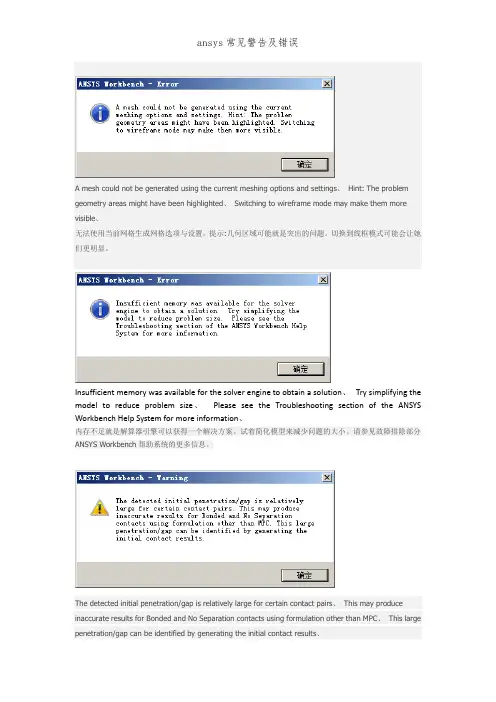
ansys常见警告及错误A mesh could not be generated using the current meshing options and settings. Hint: The problem geometry areas might have been highlighted. Switching to wireframe mode maymake them more visible.无法使用当前网格生成网格选项和设置。
提示:几何区域可能是突出的问题。
切换到线框模式可能会让他们更明显。
Insufficient memory was available for the solver engine to obtain a solution. Try simplifying the model to reduce problem size. Please see the Troubleshooting section of the ANSYS Workbench Help System for more information.内存不足是解算器引擎可以获得一个解决方案。
试着简化模型来减少问题的大小。
请参见故障排除部分ANSYS Workbench帮助系统的更多信息。
The detected initial penetration/gap is relatively large for certain contact pairs. This may produce inaccurate results for Bonded and No Separation contacts using formulation other than MPC. This large penetration/gap can be identified by generating the initial contact results.检测到的初始渗透/差距相对较大的某些接触对。
A mesh could not be generated using the current meshing options and settings、Hint: The problem geometry areas might have been highlighted、Switching to wireframe mode may make them more visible、无法使用当前网格生成网格选项与设置。
提示:几何区域可能就是突出的问题。
切换到线框模式可能会让她们更明显。
Insufficient memory was available for the solver engine to obtain a solution、Try simplifying the model to reduce problem size、Please see the Troubleshooting section of the ANSYS Workbench Help System for more information、内存不足就是解算器引擎可以获得一个解决方案。
试着简化模型来减少问题的大小。
请参见故障排除部分ANSYS Workbench帮助系统的更多信息。
The detected initial penetration/gap is relatively large for certain contact pairs、This may produce inaccurate results for Bonded and No Separation contacts using formulation other than MPC、This large penetration/gap can be identified by generating the initial contact results、检测到的初始渗透/差距相对较大的某些接触对。
ANSYS错误提示及其含义1 在Ansys中出现“Shape testing revealed that 450 of the 1500 new or modified elements violate shape warning limits.”,是什么原因造成的呢?单元网格质量不够好,尽量用规则化网格,或者再较为细密一点。
2 在Ansys中,用Area Fillet对两空间曲面进行倒角时出现以下错误:Area 6 offset could not fully converge to offset distance 10. Maximum error between the two surfaces is 1% of offset distance.请问这是什么错误?怎么解决?其中一个是圆柱接管表面,一个是碟形封头表面。
ansys的布尔操作能力比较弱。
如果一定要在ansys里面做的话,那么你试试看先对线进行倒角,然后由倒角后的线形成倒角的面。
建议最好用UG、PRO/E这类软件生成实体模型然后导入到ansys。
3 在Ansys中,出现错误“There are 21 small equation solver pivot terms。
”,是否是在建立接触contact时出现的错误?不是建立接触对的错误,一般是单元形状质量太差(例如有接近零度的锐角或者接近180度的钝角)造成small equation solver pivot terms4 在Ansys中,出现警告“SOLID45 wedges are recommended only in regions of relatively low stress gradients.”,是什么意思?"这只是一个警告,它告诉你:推荐SOLID45单元只用在应力梯度较低的区域。
它只是告诉你注意这个问题,如果应力梯度较高,则可能计算结果不可信。
"5 ansys向adams导的过程中,出现如下问题“There is not enough memory for the Sparse Matrix Solver to proceed.Please shut down other applications that may be running or increase the virtual memory on your system and return ANSYS.Memory currently allocated for the Sparse Matrix Solver=50MB.Memory currently required for the Sparse Matrix Solver to continue=25MB”,是什么原因造成的?不清楚你ansys导入adams过程中怎么还需要使用Sparse Matrix Solver(稀疏矩阵求解器)。
ansys警告和错误(持续更新)(2010-12-20 11:05:16)1、The value of UY at node 1195 is 449810067.It is greater than the current limit of 1000000.This generally indicates rigid body motion as a result of an unconstrained model. Verify that your model si properly constrained.错误的可能:1).出现了刚体位移,要增加约束2).求解之前先merge或者压缩一下节点3).有没有接触,如果接触定义不当,也会出现这样类似的情况4)材料属性设置不对会出现这种情况,例如密度设置的太离谱;2、Large negative pivot value...May be because of a bad temperature-dependent material property used in the model.出现这个错误很可能的原因是约束不够!请仔细检查模型!3、开始求解后出现以下提示,Solid model data is contaminated后来终于找到原因了有限元网格里包含一些未被划分网格的线,一般来说出现在面于面之间有重合的线,导致虽然面被划分了网格,却包含未被划分网格的线。
解决办法,把模型存为.cdb格式(去掉几何信息),然后再读取,就可以求解了命令:cdwrite,db,模型名,cdb听起来不错,不过也没遇到过,一般在划分后用一下NUMMRG命令,合并元素,以避免这种情况出现4、*** WARNING ***There are 79 small equation solver pivot terms.几个可能:1) 约束不够,但警告有79 个方程出现小主元,这一条可能性较小,但也不妨检查一下。
ansys分析显现问题(2020-07-20 09:35:55)标签:some contact elements overlap with the other contact element which can cause over constraint. 这是由于在同一实体上,即有绑定接触(MPC)的定义,又有刚性区或远场载荷(MPC)的定义,操作中注意在定义刚性区或远场载荷时避免选择不必要的DOF自由度,以消除过约束Shape testing revealed that 450 of the 1500 new or modified elements violate shape warning limits. 是什么原因造成的呢?单元网格质量不够好尽量,用规则化网格,或者再较为细密一点在用Area Fillet对两空间曲面进行倒角时出现以下错误:Area 6 offset could not fully converge to offset distance 10. Maximum error between the two surfaces is 1% of offset distance.请问这是什么错误?怎么解决?其中一个是圆柱接管表面,一个是碟形封头表面。
ansys的布尔操作能力比较弱。
如果一定要在ansys里面做的话,那么你试试看先对线进行倒角,然后由倒角后的线形成倒角的面。
建议最好用UG、PRO/E这类软件生成实体模型然后导入到ansysThere are 21 small equation solver pivot terms.;SOLID45 wedges are recommended only in regions of relatively lowstress gradients.第一个问题我自己觉得是在建立contact时出现的错误,但自己还没有改正过来;第二个也不知道是什么原因。
ansys常见警告及错误A mesh could not be generated using the current meshing options and settings. Hint: The problem geometry areas might have been highlighted. Switching to wireframe mode maymake them more visible.无法使用当前网格生成网格选项和设置。
提示:几何区域可能是突出的问题。
切换到线框模式可能会让他们更明显。
Insufficient memory was available for the solver engine to obtain a solution. Try simplifying the model to reduce problem size. Please see the Troubleshooting section of the ANSYS Workbench Help System for more information.内存不足是解算器引擎可以获得一个解决方案。
试着简化模型来减少问题的大小。
请参见故障排除部分ANSYS Workbench帮助系统的更多信息。
The detected initial penetration/gap is relatively large for certain contact pairs. This may produce inaccurate results for Bonded and No Separation contacts using formulation other than MPC. This large penetration/gap can be identified by generating the initial contact results.检测到的初始渗透/差距相对较大的某些接触对。
A mesh could not be generated using the current meshing options and settings. Hint: The problem geometry areas might have been highlighted. Switching to wireframe mode may make them more visible. 无法使用当前网格生成网格选项和设置。
提示:几何区域可能是突出的问题。
切换到线框模式可能会让他们更明显。
Insufficient memory was available for the solver engine to obtain a solution. Try simplifying the model to reduce problem size. Please see the Troubleshooting section of the ANSYS Workbench Help System for more information.内存不足是解算器引擎可以获得一个解决方案。
试着简化模型来减少问题的大小。
请参见故障排除部分ANSYS Workbench帮助系统的更多信息。
The detected initial penetration/gap is relatively large for certain contact pairs. This may produce inaccurate results for Bonded and No Separation contacts using formulation other than MPC. This large penetration/gap can be identified by generating the initial contact results.检测到的初始渗透/差距相对较大的某些接触对。
ansys分析出现问题NO.0052some contact elements overlap with the other contact element which can cause over constraint.这是由于在同一实体上,即有绑定接触(MPC)的定义,又有刚性区或远场载荷(MPC)的定义,操作中注意在定义刚性区或远场载荷时避免选择不必要的DOF自由度,以消除过约束NO.0053Shape testing revealed that 450 of the 1500 new or modified elements violate shape warning limits. 是什么原因造成的呢?单元网格质量不够好尽量,用规则化网格,或者再较为细密一点NO.0054在用Area Fillet对两空间曲面进行倒角时出现以下错误:Area 6 offset could not fully converge to offset distance 10. Maximum error between the two surfaces is 1% of offset distance.请问这是什么错误?怎么解决?其中一个是圆柱接管表面,一个是碟形封头表面。
ansys的布尔操作能力比较弱。
如果一定要在ansys里面做的话,那么你试试看先对线进行倒角,然后由倒角后的线形成倒角的面。
建议最好用UG、PRO/E这类软件生成实体模型然后导入到ansysNO.0055There are 21 small equation solver pivot terms.;SOLID45 wedges are recommended only in regions of relatively lowstress gradients.第一个问题我自己觉得是在建立contact时出现的错误,但自己还没有改正过来;第二个也不知道是什么原因。
ANSYS警告和报错信息汇总NO.0001、ESYS is not valid for line element.原因:是因为我使⽤LATT的时候,把“--”的那个不⼩⼼填成了“1”。
经过ANSYS的命令⼿册⾥说那是没有⽤的项⽬,但是根据我的理解,这些所谓的没有⽤的项⽬实际上都是ANSYS在为后续的版本留接⼝。
对于LATT,实际上那个项⽬可能就是单元坐标系的设置。
当我发现原因后,把1改成0——即使⽤全局直⾓坐标系,就没有WARNING了。
当然,直接空⽩也没有问题。
NO.0002、使⽤*TREAD的时候,有的时候明明看⽂件好好的,可是却出现 *TREAD end-of-file in data read.后来仔细检查,发现我TXT的数据⽂件⾥,分隔是采⽤TAB键分隔的。
但是在最后⼀列后⾯,如果把⿏标点上去,发现数据后⾯还有⼀个空格键。
于是,我把每个列最后多的空格键删除,,然后发现上⾯的信息就没有了。
NO.0003、 Coefficient ratio exceeds 1.0e8 - Check results.这个⼤概是跟收敛有关,但是我找不到具体的原因。
我建⽴的⼀个桥梁分析模型,尽管我分析的结果完全符合我的⼒学概念判断,规律完全符合基本规律,数据也基本符合实际观测,但是却还是不断出现这个警告信息。
有⼈知道这个信息是什么意思,怎么调试能消除吗?NO.0004、*TREAD end-of-file in data readtxt中的表格数据不完整!NO.0005、No *CREATE for *END. The *END command is ignored忘了写*END了吧,呵呵NO.0006、 Keypoint 1 is referenced by only one line. Improperly connected line set for AL command两条线不共点,尝试 nummrg命令NO.0007、 L1 is not a recognized PREP7 command, abbreviation, or macro. This command will be ignored还没有进⼊prep7,先:/prep7NO.0008、Keypoint 2 belongs to line 4 and cannot be moved同⼀位置点2已经存在了,尝试对同位置的⽣成新点换个编号,⽐如1002NO.0009、Shape testing revealed that 32 of the 640 new or modified elementsviolate shape warning limits. To review test results, please see theoutput file or issue the CHECK command.单元形状奇异,在我的模型中6⾯体单元的三个边长差距较⼤,可忽略该错误NO.0010、⽤命令流建模的时候遇到的The drag direction (from the keypoint on drag line 27 that is closestto a keypoint KP of the given area 95) is orthogonal to the areanormal at that KP. Area cannot be dragged by the VDRAG command.意思是拉伸源⾯的法向与拉伸路径垂直,不能使⽤VDRAG命令。
ansys常见警告及错误
A mesh could not be generated using the current meshing options and settings. Hint: The problem geometry areas might have been highlighted. Switching to wireframe mode may
make them more visible.
无法使用当前网格生成网格选项和设置。
提示:几何区域可能是突出的问题。
切换到线框模式可能会让他们
更明显。
Insufficient memory was available for the solver engine to obtain a solution. Try simplifying the model to reduce problem size. Please see the Troubleshooting section of the ANSYS Workbench Help System for more information.
内存不足是解算器引擎可以获得一个解决方案。
试着简化模型来减少问题的大小。
请参见故障排除部分ANSYS Workbench帮助系统的更多信息。
The detected initial penetration/gap is relatively large for certain contact pairs. This may produce inaccurate results for Bonded and No Separation contacts using formulation other than MPC. This large penetration/gap can be identified by generating the initial contact results.
检测到的初始渗透/差距相对较大的某些接触对。
这对保税可能会产生不准确的结果,没有分离的联系人使用制定货币政策委员会。
这个巨大的渗透/差距可以确定通过生成初始接触的结果。
At least one body has been found to have only 1 element in at least 2 directions along with reduced integration. This situation can lead to invalid results. Consider changing to full integration element control or meshing with more elements. Refer to Troubleshooting in the Help System for more details.
至少一个尸体被发现只有1元素至少2方向以及减少集成。
这种情况可能会导致无效的结果。
考虑改变完全整合元素控制或啮合与更多的元素。
参考故障排除帮助系统的更多细节。
Quad map meshing failed because a surface appears to be narrow with many boundary edges which could not be properly paired up for meshing. Using hard size controls on the boundary edges to force the same number of divisions may help to successfully generate a mapped mesh.
四映射网格失败是因为表面似乎狭窄许多边界边缘不能正确配对啮合。
使用硬大小控制边界的边缘,迫使相同数量的分歧可能有助于成功地生成映射网格。
The solution process was aborted as you requested.
During this solution, the elapsed time exceeded the CPU time by an excessive margin. Often this indicates either a lack of physical memory (RAM) required to efficiently handle this simulation or it indicates a particularly slow hard drive configuration. This simulation can be expected to run faster on identical hardware if additional RAM or a faster hard drive configuration is made available. For more details, please see the ANSYS Performance Guide which is part of the ANSYS Help system.
在这个解决方案中,运行时间超过了CPU时间的过度。
常常这表明缺乏所需的物理内存(RAM)有效地处理这种模拟也表明一个特别慢的硬盘配置。
这种模拟可以将相同的硬件上运行得更快,如果额外的RAM或更快的硬盘配置是可用的。
有关详细信息,请参阅ANSYS性能指南是ANSYS帮助系统的一部分。
generate mesh on selected bodies
为选中的实体生成网格
preview surface generate mesh on selected bodies 为选定的实体表面生成网格预览
add offset no ramping
添加偏移量没有增加。