高海拔工频耐压修正计算器
- 格式:xls
- 大小:19.50 KB
- 文档页数:1

-1-HYG2670F绝缘耐压测试仪使用说明书武汉华能阳光电气有限公司-2--3-第一章安全规则本章概要:●安全规定及标志●安全操作规定1.1安全规定及标志●本测试仪的安全要求符合<GB4706.1>、<IEC1010-1>标准。
●使用测试仪之前,请认真阅读本手册,务必按照手册要求的规定进行操作。
-4-高压测试线时必须握在红色绝缘棒处,绝对不可握在导电位置本章概要:●拆封和检查●输入电压及保险熔丝●安装及开机检查●储存和运输2.1拆封和检查武汉华能阳光电气有限公司产品是包装在一个使用泡沫保护的包装箱内,若用户收到产品时包装箱有破损,应检查仪器外观有无变形或面板损坏等。
如有损坏,请尽快通知武汉华能阳光电气有限公司或其经销商,并请保留包装-5-箱和泡沫材料,以便了解损坏原因。
我们的服务中心将为您提供快捷的维修服务或更换新机。
2.2输入电压及保险熔丝HYG2670系列绝缘耐压测试仪使用220/50Hz 单相电源,保险丝容量见技术参数表格。
更换保险丝前,必须先去掉输入电源线,新更换的保险丝容量需符合要求2.3安装及开机检查及位于测试仪后面板的熔断器是否完好。
确认检查完好后再次开机启动观察。
2.4储存和运输测试仪可在下列条件下储存和运输:温度:-20~60℃湿度<90%RH必须避免环境温度的急剧变化,温度的急剧变化可能会使水汽凝结于仪-6-器内部。
第三章概述本章概要:●产品简介●前面板说明●后面板说明●附件3.1产品简介HYG2670系列交/直流耐压、绝缘测试仪,是一种高性能绝缘、耐压测试仪器。
可同时显示绝缘电阻值,耐压电压、击穿电流值等,具有多种测试功能。
该系列测试仪高压输出准确度高(优于5%),漏电流测试精度高(优于5%),绝缘电阻测试速度快,既适用生产线快速化流水检测,又适合实验室多功能高精度要求。
仪器的测量原理符合《GB4706.1》、《GB3883.1》、《GB4943》安全性能检测要求,可对采用基本绝缘、附加绝缘和加强绝缘的器具进行电气强度、绝缘电阻测试。

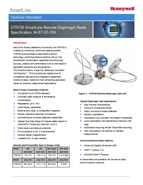
SmartLineIntroductionPart of the SmartLine® family of products, the STR700 is suitable for monitoring, control and data acquisition. STR700 products feature piezoresistive sensor technology combining pressure sensing with on chip temperature compensation capabilities providing high accuracy, stability and performance over a wide range of application pressures and temperatures.The SmartLine family is also fully tested and compliant with Experion ®PKS providing the highest level of compatibility assurance and integration capabilities. SmartLine easily meets the most demanding application needs for pressure measurement applicationsBest in Class Transmitter Features:∙ Accuracies up to 0.075% standard ∙ Automatic static pressure & temperature compensation∙ Rangeability up to 100:1 ∙ Local display capabilities∙ External zero, span, & configuration capability ∙ Polarity insensitive electrical connections ∙ Comprehensive on-board diagnostic capabilities ∙ Integral Dual Seal design for highest safety based on ANSI/NFPA 70-202 and ANSI/ISA 12.27.0 ∙ World class overpressure protection ∙ Full compliance to SIL 2/3 requirements. ∙ Modular design characteristics ∙Available with 15 year warrantyFigure 1 – STR700 Remote Diaphragm Seal UnitTypical Diaphragm Seal applications∙ High Process Temperatures ∙ Viscous or Suspended Solids ∙ Highly Corrosive Process Materials ∙ Sanitary Applications∙ Applications with Hydrogen Permeation Possibilities ∙ Level Applications with Maintenance Intensive Wet Legs∙ Applications requiring remote Transmitter Mounting ∙Tank Applications with Density or Interface MeasurementsCommunications/Output Options:∙ Honeywell Digitally Enhanced (DE) ∙ HART ®(version 7.0) ∙F OUNDATION™ Fieldbu sAll transmitters are available with the above listed communications protocols.DescriptionThe SmartLine family pressure transmitters are designed around a high performance piezo-resistive sensor. This one sensor actually integrates multiple sensors linking process pressure measurement with on-board static pressure (DP Models) and temperature compensation measurements. This level of performance allows the ST 700 to replace most competitive transmitters available today.Indication/Display OptionThe ST 700 modular design accommodates a basic alphanumeric LCD display.Basic Alphanumeric LCD Display Featureso Modular (may be added or removed in the field)o0, 90,180, & 270 degree position adjustmentso Pa, KPa, MPa, KGcm2, Torr, ATM, i4H2O, mH2O, bar, mbar, inH2O, inHG, FTH2O, mmH2O, mm HG,& psi measurement unitso 2 Lines 16 Characters (4.13H x 1.83W mm)o Square root output indication (√)DiagnosticsSmartLine transmitters all offer digitally accessible diagnostics which aid in providing advanced warning of possible failure events minimizing unplanned shutdowns, providing lower overall operational costsConfiguration ToolsIntegral Three Button Configuration OptionSuitable for all electrical and environmental requirements, SmartLine offers the ability to configure the transmitterand display via three externally accessible buttons whena display option is selected. Zero/span capabilities are also optionally available via these buttons with or without selection of the display option.Hand Held ConfigurationSmartLine transmitters feature two-way communication and configuration capability between the operator and the transmitter. This is accomplished via Honeywell’s field-rated Multiple Communication Configurator (MCT202). The MCT202 is capable of field configuring DE and HART Devices and can also be ordered for use in intrinsically safe environments. All Honeywell transmitters are designed and tested for compliance with the offered communication protocols and are designed to operate with any properly validated hand held configuration device. Personal Computer ConfigurationHoneywell’s SCT 3000 Configuration Toolkit provides an easy way to configure Digitally Enhanced (DE) instruments using a personal computer as the configuration interface. Field Device Manager (FDM) Software and FDM Express are also available for managing HART & Fieldbus device configurations.System Integrationo SmartLine communications protocols all meet the most current published standards forHART/DE/Fieldbus.o Integra tion with Honeywell’s Experion PKS offers the following unique advantages.o Tamper reportingo FDM Plant Area Views with Health summarieso All ST 700 units are Experion tested to provide the highest level of compatibility assuranceModular DesignTo help contain maintenance & inventory costs, all ST 700 transmitters are modular in design supporting the user’s ability to replace meter bodies, add indicators or change electronic modules without affecting overall performance or approval body certifications. Each meter body is uniquely characterized to provide in-tolerance performance over a wide range of application variations in temperature and pressure and due to the Honeywell advanced interface, electronic modules may be swapped with any electronics module without losing in-tolerance performance characteristics.Modular Featureso Meter body replacemento Exchange/replace electronics/comms modules*o Add or remove integral indicator*o Add or remove lightning protection (terminalconnection)** Field replaceable in all electrical environments (including IS) except flameproof without violating agency approvals.With no performance effects, Honeywell’s unique modularity results in lower inventory needs and lower overall operating costs.Performance Specifications1Reference Accuracy 2 (conformance to +/-3 Sigma)Zero and span may be set anywhere within the listed (URL/LRL) range limitsAccuracy at Specified Span, Temperature and Static Pressure:(conformance to +/-3 Sigma)Total Performance (% of Span):Total Performance = +/- √( Accuracy)2 + (Temp Effect)2Total Performance Examples: (5:1 Turndown, up to 50 o F shift)STR73D @ 20 psid: 1.03% of spanTypical Calibration Frequency:Calibration verification is recommended every four (4) yearsNotes:1.Terninal Based Accuracy – Includes combined effects of linearity, hysteresis, and repeatability. Analog output adds 0.005% of span.2. For zero based spans and reference conditions of 25o C (77o F), 0 psig static pressure, 10 to 55% R.H, and 316Stainless Steel barrier diaphragms3. Specification applies to transmitter with 2 seals. Apply a factor of 1.5 for temperature effect of capillary lengths greater then 10 feet.1Ambient Temperature Limit is a function of Process Interface Temperature. (See Figures 3 & 4) LCD Display operating temperature -20︒C to +70︒C . Storage temperature -30︒C to 80︒C4Consult factory for MAWP of ST 700 transmitters with CRN approval.Figure 2 - Supply voltage and loop resistance Figure 3 - Ambient temperature LimitsFigure 4 - STR700 Remote Seals operable limits for pressure vs. temperatureNOTE: Pressure transmitters that are part of safety equipment for the protection of piping (systems) or vessel(s) from exceeding allowable pressure limits, (equipment with safety functions in accordance with Pressure Equipment Directive 97/23/EC article 1, 2.1.3), require separate examination.Minimum recommended span for STR73D Transmitter with one Remote SealFigure 5– Typical Maximum capillary length and diaphragm size chartFigure 6 - STR700 transmitter with remote diaphragm seals shown mounted on a tankReference Dimensions Horizontal MountingReference Dimensions Horizontal Mounting (cont’d)Figure 7 — Approximate horizontal mounting dimensions for Remote Seal Transmitter Reference Dimensions Vertical MountingReference Dimensions Vertical Mounting (cont’d)Figure 8 — Approximate vertical mounting dimensions for Remote Seal TransmitterFlush Flanged Seal DimensionsFigure 9 - Seal Dimensions (Flush Flanged)Figure AFigure BFigure CFigure DFlush Flanged Seal with LowerFigure 10- Seal Dimension (Flush Flanged)Flush Flanged Seal with LowerFlush Flanged Seal with LowerNote: 0.90 dimension is 0.70 for 4.1” Dia DiaphragmFlanged Seal with Extended DiaphragmFigure 11 — Seal Dimensions (Extended Diaphragms)Pancake SealFigure 12 — Seal Dimensions (Pancake)Chemical Tee “Taylor Wedge” SealFigure 13 — Seal Dimensions (Chemical TEE “Taylor Wedge” SealsSeal with Threaded Process ConnectionFigure 14— Seal Dimensions (Threaded Process Connection Seals) Sanitary SealFigure 15— Seal Dimensions (Sanitary Seals)Saddle SealFigure 16—Seal Dimensions (3” Saddle Seal)Figure 17—Seal Dimensions (4” Saddle Seal) Calibration RingFigure 18— Calibration RingCommunications Protocols & DiagnosticsHART ProtocolVersion: HART 7 Power SupplyVoltage: 10.8 to 42.4Vdc at terminals Load: Maximum 1440 ohms. See Figure 2.Minimum Load: 0 ohms. (For handheld communications a minimum load of 250 ohms is required)Foundation Fieldbus (FF)Power Supply Requirements Voltage: 9.0 to 32.0Vdc at terminals Steady State Current: 17.6mAdc Software Download Current: 27.4mAdc* AI block may have two (2) additional instantiations. All available function blocks adhere to FOUNDATION Fieldbus standards. PID blocks support ideal & robust PID algorithms with full implementation of Auto-tuning. Link Active SchedulerTransmitters can perform as a backup Link Active Scheduler and take over when the host is disconnected. Acting as a LAS, the device ensures scheduled data transfers typically used for the regular, cyclic transfer of control loop data between devices on the Fieldbus. Number of Devices/Segment Entity IS model: 6 devices/segment Schedule Entries18 maximum schedule entries Number of VCR’s: 24 maxCompliance Testing: Tested according to ITK 6.0.1Software DownloadUtilizes Class-3 of the Common Software Download procedure as per FF-883 which allows the field devices of any manufacturer to receive software upgrades from any host.Honeywell Digitally Enhanced (DE)DE is a Honeywell proprietary protocol which provides digital communications between Honeywell DE enabled field devices and Hosts. Power SupplyVoltage: 10.8 to 42.4Vdc at terminals Load: Maximum 1440 ohms See Figure 2.Standard DiagnosticsST 700 top level diagnostics are reported as either critical or non-critical and readable via the DD/DTM tools or integral display as shown below.Refer to ST 700 manuals for additional level diagnostic informationOther Certification OptionsMaterials oNACE MRO175, MRO103, ISO15156Approval Certifications:Approval Certifications: (Continued)1.Operating Parameters:Voltage= 11 to 42 V DC= 10 to 30 V (FF) Current= 4-20 mA Normal = 30 mA (FF)2.Intrinsically Safe Entity Parametersa. Analog/ DE/ HART Entity Values:Vmax= Ui = 30V Imax= Ii= 105mA Ci = 4.2nF Li =984 uH Pi =0.9WTransmitter with Terminal Block Revision E or Later )Vmax= Ui = 30V Imax= Ii= 225mA Ci = 4.2nF Li = 0 Pi =0.9WNote : Transmitter with Terminal Block Revision E or laterThe revision is on the label that is on the module. There will be two lines of text on the label: ∙First is the Module Part #: 50049839-001 or 50049839-002∙Second line has the supplier information, along with the REVISION:XXXXXXX-EXXXX, THE “X” is production related, THE POSITION of the “E” IS THE REVISION.b. Foundation Fieldbus- Entity ValuesVmax= Ui = 30V Imax= Ii= 180mA Ci = 0nF Li = 984 uH Pi =1WTransmitter with Terminal Block Revision F or Later )Vmax= Ui = 30V Imax= Ii= 225mA Ci =0nF Li = 0 Pi =1 WFISCO Field DeviceVmax= Ui = 17.5VImax= Ii= 380 mA Ci = 0nF Li = 0 Pi =5.32 WNote : Transmitter with Terminal Block Revision F or laterThe revision is on the label that is on the module. There will be two lines of text on the label: ∙First is the Module Part #: 50049839-003 or 50049839-004∙Second line has the supplier information, along with the REVISION:XXXXXXX-EXXXX, THE “X” is production related, THE POSITION of the “E” IS THE REVISION.Application DataLiquid Level: Closed TankDetermine the minimum and maximum pressure differentials to be measured (Figure 16).PMin = (SGp x a) - (SGf x d)= LRV when HP at bottom of tank= –URV when LP at bottom of tank PMax = (SGp x b) - (SGf x d)= URV when HP at bottom of tank= –LRV when LP at bottom of tank Where:minimum level at 4mAmaximum level at 20 mAa = distance between bottom tap andminimum levelb = distance between bottom tap andmaximum leveld = distance between tapsSG f = Specific Gravity of capillaryfill fluid (See Page 6 “Mat erial Specifications” for values.)SG p = Specific Gravity of process fluidMaxLevelMinLevelTransmitter above datumMaxLevelMinLevelMaxLevelMinLevelFigure 16—Closed tank liquid level measurement distanceApplication Data (Cont’d)Density or Interface*Calculate the minimum and maximum pressure differentials to be measured (Figure 19).P min = (SG min – SG f ) x (d); minimum density, 4mA outputP max = (SG max – SG f ) x (d); maximum density, 20mA outputWhere:d = distance between the tapsSG max = maximum Specific GravitySG min = minimum Specific GravitySG f = Specific Gravity of capillary fill fluid (See Page 6 “Material Specifications” for values.)Figure 19- Density, direct acting transmitterconfigurationSeal ConfigurationsFigure 20—Flush Flange SealsFlush Flange Seals can be used with differential, gauge and absolute pressure transmitters and are available with 3” ANSI Class 150, ANSI Class 300 and DIN DN80-PN40 process connections. Flush flange seals can also be provided with Lowers. Lowers are essentially calibration rings, which allow flushing connections if needed.Figure 21 — Flange Seal with Extended Diaphragm Flange Seal with Extended Diaphragm can be used with differential, gauge and absolute pressure transmitters and are available with 3” and 4” ANSI Class 150, ANSI Class 300, DIN DN80-PN40 and DIN DN100-PN40 processconnections. 2”, 4” and 6” extension len gths are available.Figure 22—Pancake SealsPancake Seals can be used with differential, gauge and absolute pressure transmitters and are available with 3” ANSI Class 150, 300 and 600 process connections.Figure 23— Chemical Tee “Taylor” Wedge Chemical Tee “Taylor” Wedge can be used withdifferential pressure transmitters and are available with Taylor Wedge 5” O.D. process connection .Seal Configurations (cont’d)Figure 24— Seals with Threaded ProcessConnectionsSeals with Threaded Process Connections can be usedwith differential, gauge and absolute pressuretransmitters and are available with ½”, ¾” and 1” NPTFemale process connections.Figure 25 — Sanitary SealsSanitary Seals can be used with differential, gauge andabsolute pressure transmitters and are available with 3”and 4” Tri-Clover-Tri-Clamp process connections.Figure 26— Saddle SealsSaddle Seals can be used with differential, gauge andabsolute pressure transmitters and are available with 3”and 4” (6 bolt or 8 bolt designs) process connections.Figure 27 — Calibration RingsCalibration Rings are available with Flush Flange Sealsand Pancake Seals. Flushing ports (1/4” or ½”) areavailable with calibration rings.Figure 28 — Stainless Steel Armor and PVC CoatedStainless Steel Armor CapillariesStainless Steel Armor and PVC Coated Stainless SteelArmor Capillaries are available with Honeywell RemoteSeal Solutions.Figure 29 —2” Stainless Steel Nipples2” Stainless Steel Nipples are available for Close-Coupled remote seal solutionsFigure 30 — Welded Meter Body for All-WeldedRemote Seal SolutionWelded Meter Body for All-Welded Remote Seal Solution.The welded ST 800 meter body is an important part of anAll-Welded Remote Seal Solution, which is commonlyused in Vacuum applications.Model Selection GuideModel Selection Guides are subject to change and are inserted into the specifications as guidance only.Prior to specifying or ordering a model check for the latest revision Model Selection Guides which are published at:/en-US/pages/default.aspxModel STR700(DP, GP) Remote SealsModel Selection GuideNote:Remote seal system pressure rating is body rating or seal rating, whichever is less.11 Limited vacuum availability.12Minimum static pressure requirement. No vacuum allowed. See Specifications 34-ST-03-88 Figure 15In-Line Gauge All weldedBodyDual Head DP g. Seal OptionFlush FlangedSeal Calibration RingsFlushingConnectionsand Plugs 41 Standard facing 125-250 AARH RF (raised face) serrated surface finish.4 P lastic P lugs are TE MP ORARY ONLY to protect threads and MUST be RE MOVE D before installation5 Tantalum Upper insert has Tantalum w etted parts and 316 SS or CS non-w etted partsNote: Remote seal system pressure rating is body rating or seal rating, w hichever is less.Flush FlangedSealwith Lower1 Standard facing 125-250 AARH RF (raised face) serrated surface finish.6 Bolt material w ill be same as Upper Material. How ever, if Table I bolts/nuts material is NACE or B7M, seal bolt material w ill be 304 SS NACE.4 P lastic P lugs are TE MP ORARY ONLY to protect threads and MUST be RE MOVE D before installationNote: Remote seal system pressure rating is body rating or seal rating, w hichever is less.Flange Sealwith ExtendedDiaphragmCalibration RingsPancake SealFlushingConnectionsand Plugs41 Standard facing 125-250 AARH RF (raised face) serrated surface finish.4 P lastic P lugs are TE MP ORARY ONLY to protect threads and MUST be RE MOVE D before installation 7 Tantalum Body has Tantalum w etted parts and 316 SS non-w etted partsNote: Remote seal system pressure rating is body rating or seal rating, w hichever is less.Chemical Tee"Taylor" WedgeSeal withThreadedProcessConnection1 Standard facing 125-250 AARH RF (raised face) serrated surface finish.4 P lastic P lugs are TE MP ORARY ONLY to protect threads and MUST be RE MOVE D before installation8 If Table I Bolts and Nuts material option is NACE, Bolts and Nuts w ill ship w ith Alloy Steel NACE and MAWP may change. Note: Remote seal system pressure rating is body rating or seal rating, w hichever is less.Sanitary Seal 9Saddle Seal9 All sanitary seals have dairy grade 3A approval.10 Bolts are not included w ith "body only" selection.11 If Table I Bolts and Nuts material option is NACE, seal bolt material w ill be 304 SS NACE. Note: Remote seal system pressure rating is body rating or seal rating, w hichever is less.3NAMUR Output Limits 3.8 - 20.5mAdc can be configured by the customer or select custom configuration Table VcNEPSI Explosion proof, Intrinsically Safe & Non-incendiveIECEx Explosion proof, Intrinsically Safe & Non-incendiveSAEx/CCoE Explosion proof, Intrinsically Safe & Non-incendive INMETRO Explosion proof, Intrinsically Safe & Non-incendive ApprovalsNo Approvals RequiredFM Explosion proof, Intrinsically Safe, Non-incendive, & Dustproof CSA Explosion proof, Intrinsically Safe, Non-incendive, & Dustproof ATEX Explosion proof, Intrinsically Safe & Non-incendive TABLE III Agency Approvals (see data sheet for Approval Code Details)STR74G STR73DFM Approvals SM is a service mark of FM GlobalHastelloy® is a registered trademark of Haynes InternationalMonel 400® is a registered trademark of Special Metals Corporation.HART® is a registered trademark of HART Communication Foundation. FOUNDATION TM Fieldbus is a registered trademark of Fieldbus Foundation. Teflon® is a registered trademark of DuP ont.Neobee® is a registered trademark of Stepan Company.Syltherm® 800 is a Trademark of Dow Corning CorporationKlinger® C-4401 is a registered trademark of THE RMOSE AL, INC GRAFOIL® is a registered trademarks of GrafTech International Holdings Inc Gylon® 3510 is registered trademark of Garlock Sealing TechnologiesTri-Clover Tri-Clamp® is a registered trademark of Alfa-LavalSpecifications are subject to change without notice.34-ST-03-104April 2014For more informationProcess Solutions Honeywell1250 W Sam Houston Pkwy S Houston, TX 77042Honeywell Control Systems LtdHoneywell House, Skimped Hill Lane Bracknell, England, RG12 1EB Shanghai City Centre, 100 Jungi Road Shanghai, China 20061 .Relevant Solutions 1.888.858.3647。

w w w.1718p or t.co m®717 SeriesPressure Calibrators说明书简介Fluke 717 系列压力校准器是一种轻巧袖珍,电池供电的 5 位数仪器,能够执行下列校准和测量功能:•校准 P/I(压力对电流)变送器•使用一 1/8 英寸 NPT 压力接口和一内部压力传感器测量压力•通过一 Fluke 700 系列压力模块测量压力•测量高达 24 mA(毫安)的电流•供应回路电压(至 24 V 直流电)•同时显示压力和电流测量值•计算“百分比”模式中的 mA(安培)百分数•计算“误差百分比”模式中的 mA(安培)误差717 系列压力校准器(以下简称为“校准器”)包括下列各机型:•717 1G •717 30G •717 100G •717 300G •717 500G •717 1000G •717 1500G •717 3000G •717 5000G满刻度压力传感器如“压力指标”下的“技术指标”部分所列。
校准器是一种IEC 61010,I 类 30 V,污染第 2 级仪器。
I 类仪器专门用于防止瞬态低能电源,例如电路或拷贝机的损害。
校准器包装内附有一皮套,一已装配的 9 V 电池,一组测试导线和鳄鱼夹,以及 14 种语言的说明书。
若校准器有损坏或缺件,请立即与供货单位联系。
PN 690013 March 1998, Rev. 2, 3/06 (Simplified Chinese)1998-2006 Fluke Corporation. All rights reserved. Printed in USA.ww w .1718p or t .co m 输入单位校准器根据下列单位测量与显示压力传感器输入端。
• psi (磅/平方英寸) • inH 2O@4 °C • inH 2O@20 °C • cmH 2O@4 °C • cmH 2O@20 °C • Bar (巴) • mbar (毫巴) • kPa (千帕) • inHg@0 °C • mmHg (毫米汞柱)• kg/cm 2(千克/平方厘米)如果装置选择不当,Fluke 700P 压力模块的输出可能会太低而无法显示, 或导致校准器显示出OL (过载)的字眼。

常州市优策电子有限公司UC9000 系列AC/DC/IR多功能耐压测试仪用户使用手册(V1.0)公司:常州市优策电子科技有限公司地址:江苏省常州市钟楼区迎宾路58-18号(213002)电话:*************传真:*************网址: 版本历史:本说明书将不断完善以利于使用。
由于说明书可能存在的错误或遗漏,仪器功能的改进和完善,技术的更新及软件的升级,说明书将做相应的调整和修改。
第1章准备使用 (1)1.1开箱检查 (1)1.2使用注意事项 (1)1.3移动时的注意要点 (2)1.4检查电源和保险丝 (3)1.4.1切换电源电压 (3)1.4.2检查并替换保险丝 (3)1.5连接交流电源线 (3)1.6接地 (4)1.7操作检查 (4)1.8仪器的其它特性 (5)第2章操作规范和措施 (6)2.1禁止的操作行为 (6)2.2紧急情况的处理 (6)2.3测试中的预防措施 (7)2.4高压测试警告 (7)2.5有故障仪器的危险状态 (8)2.6保证长时间无故障使用的条件 (8)2.7日常检查 (9)第3章仪器面板概述 (10)3.1前面板说明 (10)3.2后面板说明 (11)3.3仪器性能概述 (13)第4章基本操作 (17)4.1仪器界面结构概述 (17)4.2显示页面和参数说明 (17)4.2.1 测量显示页面 (18)4.2.2 列表显示页面 (18)4.3测量设置页面 (19)4.3.1 测量配置页面 (19)4.4测试项目页面和参数说明 (20)4.4.1 AC交流耐压参数设置 (21)4.4.2 DC直流耐压参数设置 (21)4.4.3 IR绝缘电阻参数设置 (22)4.4.4 OS开短路检测参数设置 (23)4.5测试功能原理与使用说明 (23)4.5.1 启动测试 (24)4.5.2 接地连接测试 (24)4.5.3 测试电压上升 (25)4.5.4 DC充电电流检测 (25)4.5.5 高压测试 (25)4.5.6 测试电压下降 (25)4.5.7 防电墙功能 (26)4.5.8 电流超限与电弧侦测(ARC)功能 (26)4.5.9 不合格判断 (27)4.5.10 测试结果处理 (27)4.5.11 STOP (28)第5章系统设置 (29)5.1系统设置(SYSTEM SETUP) (29)显示风格(SKIN) (29)语言(LANGUAGE) (29)按键音(KEY SOUND) (29)密码(PASSWORD) (29)日期和时间 (30)5.2接口设置(INTERFACE SETUP) (30)接口模式 (30)RS232C设置 (30)5.3系统信息(INTERFACE SETUP) (30)5.4固件升级(FIRMWARE UPDATE) (31)第6章存储与调用 (32)6.1存储系统概述 (32)6.2文件列表(FILE LIST) (32)第7章附录接口 (34)第1章准备使用本章讲述当您收到仪器后必须进行的一些检查,在安装使用仪器之前必须了解和具备的条件。
威远图公司简介北京威远图仪器有限责任公司(简称WELTOP),是一家致力于空间数据的获取与应用开发、空间信息系统集成、空间信息服务的高新技术企业,创建于1997年1月。
公司自成立以来,一直本着“真诚、服务、创新、发展”的企业精神,“以卓越的方式完成每一件事”的原则,集测绘设备销售、软件开发、信息系统集成、空间信息生产与服务为一体,短短几年时间里,已发展成为一家集空间地理信息和应用专业软件的研制和开发、空间地理信息增值服务、大型GIS工程承接为一体的全国性知名品牌企业,业务范围涵盖了整个测绘行业及服务于公众地理信息的所有工作范畴。
2000年1月又分离出北京威远图数据开发有限公司,侧重于软件和系统工程的开发和研究。
现在公司的产品与服务涉及领域包括国土、交通、水利、海洋、石化、电力、市政、农业、金融、商业、咨询等行业,在测绘行业中赢得了引人瞩目的一席之地。
公司的主要业务范围包括:测绘/地理信息采集设备、计算机与专业应用软件系统的开发/销售、以及相关的技术咨询和服务。
目前主要产品分为软、硬件两大类,有公司自己开发研制的Cito和SV系列测绘成图软件、TOP 系列测绘软件(平差及通讯等)、水利断面软件、道路测设一体化系统软件、地下管线测绘及管理软件、建筑物沉降分析软件、掌上测图系统、数字水准软件、数字矿山测绘系统以及房产测量师软件;另外我公司还承接GIS工程,已经推出并得到成熟应用的GIS系统有:房产测绘信息管理系统、矿产资源管理信息系统、银行营业网点管理系统、通用测绘信息化管理系统、地下管网信息管理系统等;配套的硬件产品有全站仪、GPS、绘图仪、扫描仪等。
2002年,威远图公司入住中关村德胜科技园区,同时获得北京市西城区政府下属隆达集团风险注资,被北京市认证为高新技术企业以及软件企业、获得北京市规划委员会颁发的测绘软件及地理信息系统开发的乙级资质,同年与美国知名企业Autodesk公司携手,作为Autodesk GIS产品中国测绘行业总代理,成为测绘行业唯一的一家ADN全球开发联盟成员。

YTC6430工频输电线路参数测试仪用户操作手册尊敬的顾客感谢您购买本公司YTC6430工频输电线路参数测试仪。
在您初次使用该仪器前,请您详细地阅读本使用说明书,将可帮助您熟练地使用本仪器。
我们的宗旨是不断地改进和完善公司的产品,因此您所使用的仪器可能与使用说明书有少许的差别。
如果有改动的话,我们会用附页方式告知,敬请谅解!您有不清楚之处,请与公司售后服务部联络,我们定会满足您的要求。
由于输入输出端子、测试柱等均有可能带电压,您在插拔测试线、电源插座时,会产生电火花,小心电击,避免触电危险,注意人身安全!◆慎重保证本公司生产的产品,在发货之日起三个月内,如产品出现缺陷,实行包换。
三年(包括三年)内如产品出现缺陷,实行免费维修。
三年以上如产品出现缺陷,实行有偿终身维修。
◆安全要求请阅读下列安全注意事项,以免人身伤害,并防止本产品或与其相连接的任何其它产品受到损坏。
为了避免可能发生的危险,本产品只可在规定的范围内使用。
只有合格的技术人员才可执行维修。
—防止火灾或人身伤害使用适当的电源线。
只可使用本产品专用、并且符合本产品规格的电源线。
正确地连接和断开。
当测试导线与带电端子连接时,请勿随意连接或断开测试导线。
产品接地。
本产品除通过电源线接地导线接地外,产品外壳的接地柱必须接地。
为了防止电击,接地导体必须与地面相连。
在与本产品输入或输出终端连接前,应确保本产品已正确接地。
注意所有终端的额定值。
为了防止火灾或电击危险,请注意本产品的所有额定值和标记。
在对本产品进行连接之前,请阅读本产品使用说明书,以便进一步了解有关额定值的信息。
请勿在无仪器盖板时操作。
如盖板或面板已卸下,请勿操作本产品。
使用适当的保险丝。
只可使用符合本产品规定类型和额定值的保险丝。
避免接触裸露电路和带电金属。
产品有电时,请勿触摸裸露的接点和部位。
在有可疑的故障时,请勿操作。
如怀疑本产品有损坏,请本公司维修人员进行检查,切勿继续操作。
请勿在潮湿环境下操作。

Trial Weight Technical Note January 2019How to calculate a trial weight amount and location, both manually and using the AMS 2140 balancing program calculator.The point in calculating a trial weight for a balancing procedure is to change the rotating element’s response from the as-found imbalanced condition (Reference Run) to another condition of imbalance. The goal is to affix a trial weight that changes the vibration response vector by either 30% lower or higher amplitude (Mils) or by 30 degrees or more of phase change (known as the 30/30 rule). This can be a bit tricky, as the desired outcome is to add enough weight to achieve the 30/30 change in response without adding so much weight as to damage the machine. Technicians can and do develop rules of thumb that assist in the determination of amount and placement of trial weights, and some even ‘guess’ (which really are educated estimates, not guesses) based on personal history and familiarity of a specific machine. But how does one properly estimate a trial weight if no prior history exists?The first step is to gather some information about the machine: What is the operational speed of the machine? What does the rotor weigh? What is the resonance frequency of the machine in relationship to the operational speed? Where will sensors be placed (measurement plane)? Where the weights be mounted (trial and weight correction radius (radii) and plane(s))? How will Phase be measured? Will this be a single or dual plane balance? After gathering the machine’s descriptive data,a manual calculation of the force exerted by the additional weight should be carried out to check for excessive force.This data is summarized in the table below:*These values are for using a physical accelerometer and converting to the units used for display. These settings may seem counter-intuitive to the astute user, as normally there is a 180 degree correction using an accelerometer and displaying in Mils of displacement to account for the phase shift in the math from the conversion. However, the unit is already correcting for the math phase shift, so these are the correct settings.Heavy Spot Location = ϴ + Φ + C - LTrial Weight Location = Heavy Spot Location - or + 180 degreesNotice that when a ‘guess’ is made, the trial weight is either placed in the hemisphere containing the light spot or the trial weight is placed in the hemisphere containing the heavy spot. Either way, the resultant imbalance vector is changed enough to cause a 30-degree or 30% change in amplitude. This is why the act of ‘guessing’ sometimes will work, but that method is not a best practice.For an illustrative example, if the sensor and tach are in the same location, then ϴ = 0. And if the display units are set to mils and one is using an accelerometer to acquire the reference and trial runs, then C = 0. This simplifies the equation to just subtracting the System Lag (L) reading from the phase (Φ) reading. Should the user happen to set up the balancing job in this manner, and then just Ignore the System Lag component, the phase reading will be the only component left. To see this, let us assume that the phase reading is 120 degrees. Therefore, we know that the heavy spot is preceding the high spot by 120 degrees. Assuming the tach and the sensor are both mounted at Top Dead Center (TDC) of the shaft, and rotation is CCW, then the actual location of the heavy spot is at 120 degrees as counted against rotation, or at 120 degrees clockwise (about 4 O’clock) from TDC. Because we want to place the trial weight opposite the heavy spot, we add or subtract 180 from 120 and get 300 degrees (or -60 degrees, so we would count with rotation since the -60 value is negative, but either way we wind up at the same spot of 300 degrees as counted against rotation from TDC, or about 10 O’clock. Note that this is closeto the same spot as the light spot of the complete calculation above, which is: Trial Wt. Location = 120 (phase reading) –45 (system lag, below resonance) + 180; or 75 + 180 = 255 degrees. This means that putting a trial weight at either 255 or 300 degrees will likely reduce the 1XRPM vibration because we have arrived in the correct hemisphere on the rotor at nearly the same location quite by accident.Calculating the correct location for mounting a trial weight is best not left up to chance. Understanding the machine’s response and operational speed relative to the machine’s resonance frequency is critical to deriving the ‘correct’ location to mount the trial weight. Use the full calculation above if possible.Now to the calculation of the appropriate Trial Weight amount. There are two commonly used equations to calculate the amount of weight to add to the shaft. First, there is the equation using an estimated amplification factor:Trial Weight (oz.) = (Reference Run Amplitude (inches) X Rotor Weight (Ounces))/((Amplification Factor) X Trial Weight radius location))Note that this equation does not use the speed of the rotor to calculate the needed trial weight, and this equation also estimates the actual imbalance in the rotor. For this equation, the user needs to convert given numbers, such as Mils to Inches (4 Mils = 0.004 inches); and rotor weight is often given in pounds, so multiplying by 16 (oz/lb.) will give the correct weight in ounces. Note that the Amplification Factor is unitless and is just an estimation, so the ‘guess’ of 3 used here is a source of error! However, the goal again is simply to change the system response, so this estimated value of 3 will work in a majorityof cases. Use a higher number (4 or 5) if you are closer to resonance, but beware – balancing near a resonance frequencyis difficult, if not impossible, due to the rapidly-changing phase readings. Once the trial weight response is acquired, then the actual influence coefficient and system lag numbers are known, so these are used to calculate the correction weight amount and location (or weights at discrete locations).Another way to calculate the Trial weight amount is to use this equation, which uses the RPM of the machine:Trial Weight (oz.- inches) = (56,320 X Rotor Weight (lbs.))/(RPM)2Note that this trial weight calculation only requires the rotor weight and RPM. However, the result is in ounce – inches,so the actual weight to be added must be divided by the radius in inches. Note that the equation result is NOT ounces/inch, but oz. – inches!So, how are these two equations related? Well, the common factors are the rotor weight (oz.) and the trial weight radius (inches). Other than those, the first equation needs to have the Reference run amplitude and the amplification factor,while the second equation divides through by the square of the speed, which is related to the force in lbs. being generated. The force generated is amplified by the value from the system response curve, which we estimated as 3.Here is a calculation using a rotor weight of 1200 lbs at 1800 RPM with a weight radius of 60 inches:TW = (56,320 * 1200)/(18002 * 60) = 0.348 ouncesFrom the first equation, the TW = ((.003 * 19,200)/(3 * 60)) = 0.32 ing 4 mils (0.004 inches) instead of three mils (0.003 inches) gives 0.43 ounces to use for the trial weight.From the Balancing Downloadable Program (DLP) calculator in the AMS 2140, several options are available, including the option to estimate trial weights. The information needed to estimate the trial weight is the same as in the above manualcalculations: Rotor Weight (lbs.); Trial Weight Radius (inches); Amplification Factor Estimate (3); and System Lag (enter 45 if operating speed is below resonant frequency, or 135 if RPM is above resonant frequency. The sensor lag field below is NOT the angle between the sensor and tach, but is an electronic sensor lag hold-over from slower electronic system front ends. Note that the program has already acquired the reference run data, so the instrument already has the initial vibration displacement amplitude and phase (high spot) information. Finally, the angle between the sensor and the tach is set by the user in the system setup.Once the trial weight has been calculated, the F12 ‘Insert to Trial Weight’ key can be pressed to input the trial weight into the calculations. Should you discover that the weight is not available, you can manually enter the actual trial weight used and the location at which the trial weight is placed, indicated by the red colored fields above. Best practice is to attach at the amount and location suggested, but minor adjustments can be made if needed.Finally, one should carry out the equation to determine the additional force added to the system, which is give by:F ub (lbs.) = 0.002841 X ω2 (cps) X Wt.Trial (lbs.) X Radius WT (inches) where:F ub is the Force of the added unbalance from the trial weight (assumes a perfectly balanced rotor).ω2 is the radian cyclic speed, which is (2 π N)2 where N = the actual turning speed in Hertz (cps).Wt.Trial is the weight of the trial weight added to the rotor. Here we are assuming a perfectly balanced rotor and calculating only the added unbalance of the trial weight.Radius WT is the rotorline center to the trial weight mounting radius.EmersonReliability Solutions835 Innovation Drive Knoxville, TN 37932 USA +1 865 675 2400 /ams The Emerson logo is a trademark and service mark of Emerson Electric Co. The AMS logo is a mark of one of the Emersonfamily of companies. All other marks are the property of their respective owners.The contents of this publication are presented for informational purposes only, and while diligent efforts were made to ensure their accuracy, they are not to be construed as warranties or guarantees, express or implied, regarding the products or services described herein or their use or applicability. All sales are governed by our terms and conditions, which are available on request. We reserve the right to modify or improve the designs or specifications of our products at any time without notice.The table below gives an example of adding a 6 gram (1 gram = 0.00220462 lbs.) trial weight thumbscrew at a radius of1.75 inches running at 3500 RPM (3500/60 = 58.33 Hz).In other words, the addition of a 6 gram weight at a speed of 3500 RPM and a radius of only 1.75 inches results in an additional centripetal force of about 9 lbs.! This is the additional force that the rotor’s internal structure and bearings must absorb and not break. To calculate the total imbalance force exerted on the machine, a vector resolution must be calculated from the initial reference run vector and the trial weight run vector. Correction weights can then be calculated and located to bring the rotor into a balanced operating condition.。
高原地区电气设备海拔修正系数的选用【摘要】笔者从实际的电气工程出发,对高原地区电气设备海拔修正系数的选用进行分析和探讨,希望对大家有所借鉴和帮助。
【关键词】高原地区;电气设备;海拔修正;系数选用近些年来,随着党中央产业援藏政策的不断发展和深入,越来越多援藏企业进入西藏。
企业发展动力先行。
陆续有査龙水电站、羊卓雍湖抽水蓄能电站以及满拉水利枢纽工程等建立在高原上。
这些电站都建立在高原地区,海拔高度都在3600米以上。
海波高程增加,那么空气的密度以及湿度也会随着降低。
因此,空气的间隙以及瓷绝缘放电的特性就会降低。
在此情况下,需要进行外绝缘强度的补偿。
而针对电气设备的外绝缘补偿计算,由于关于此的研究较少,国内也是刚刚起步,在这方面的经验较少,国外也是一样,因此使用什么方法来进行计算还没有确定。
这给工作人员的电气设备订货工作带了较大的阻碍和困难。
因此,笔者所在的单位和许多的研究所以及大学开展了有关的研究和探讨,这些单位有四川联合大学、武汉高压研究所以及西安高压研究所等。
在沟通之后,我们在上述电站的电器外绝缘补偿计算上达成了一致的意见。
我们可以在表1中看到每个电站环境状况。
表1 每个电站环境状况电站的名称海拔高程年平均气温年平均大气压年平均绝对温度羊湖电站3600 8.5 66 5.8査龙电站4360 -1.2 60.7 3.6那曲变电站4600 -1.9 58.7 3.4满拉电站4200 3.64 61.1 2.891 海拔修正系数计算公式的选择关于海拔修正系数计算公式很多,那么如何进行筛选是一个问题。
我们可以参考国标标《GB311.1-83》,也可以参考《电力工程设计手册》。
此外,还可以参考使用比湿概念的计算方法,该方法是武汉高压研究所等研究所推荐的。
笔者通过对西藏地区的电气设备运作状况进行考察后发现,这些电气设备的外绝缘在强度方面的下降程度是不同的,造成这种现象的主要原因是海拔高度不同,气象因素也就不同。
基于特殊环境因素下高、低压成套开关设备设计和制造的探讨作者:广州白云电器设备股份有限公司电气研究所杨成懋,王义,张宇怀来源:赛尔输配电产品应用开关卷总第82期摘要:本文根据目前市场需求,结合国家对环境技术的研究,提出高原环境和高污秽环境下对高低压成套开关设备的影响。
根据这些影响提出解决相关的技术问题的措施和方案关键点,并具体运用到实际的设计过程中,最终保障使用两类特殊环境下的产品顺利开发起到指导作用,同时保证产品质量,满足了社会的需求。
关键词:市场需求,研发方向,环境技术,设计,工艺前言:迈入二十一世纪以来,我们国家在经济、政治和文化等各个层面都得到快速稳定发展,尤其经济的快速发展,不仅给中国各行各业的发展带来了勃勃生机,同时也深刻的影响着人们的思想观念、行为方式。
行业及其所生产的产品发展方向,必然受到其所在的业务环境、市场需求发展方向、以及国家政策等方面的影响,同时也与使用者思想观念、行为方式有密切的联系。
高、低压成套开关设备,作为对电能的接受、输送、分配、控制及保护作用的电器产品,如何来适应各种各样的需求;如何规划其发展方向,产品的研发方向该如何确定,这些问题摆在行业领导企业管理者面前的重大战略问题。
解决这些问题,应该根据市场的需求和国家政策的引导,来正确决策产品的发展,满足电力行业的不同环境使用场合以及当前和未来的技术、功能的需要;同时还应与基本国情、国家未来经济、社会发展的整体规划的需求相协调。
白云电器作为在华南地区专业于输变配电领域的大型电器制造企业,针对市场环境的发展,以优良的产品服务社会为宗旨,不断提升产品质量;综合市场环境和国家政策的指导,在高、低压成套开关设备领域深耕细作、固本强基,不断地研发和完善满足顾客需求的各种技术方案,其中包括两项专门根据环境技术来确立的研发方向,下面根据研发的情况,跟同行共同分享、探讨。
一、环境因素确定的高低压成套开关设备的两大发展方向针对环境因素而确定产品的发展方向,也是目前高、低压成套开关设备的发展方向之一,目前市场需求提出了两大发展方向。