SA.31m
- 格式:pdf
- 大小:810.84 KB
- 文档页数:2


r at epididy mis[J].H isto chem Cell Biol,1998,109(5-6): 431-447.[10]Coo per T G.Interactio ns betw een epididy mal secr et ionsand sper matozoa[J].J Repro d F ertil Suppl,1998,53:119-136.[11]M oor e H D.Co ntr ibut ion of epididy mal factor s to sper mmatur ation and sto rag e[J].Andro log ia,1998,30(4-5):233-239.[12]Dacheux JL,Gatti JL,Dacheux F.Contr ibut ion of epidid-ymal secr etor y pro teins fo r sper matozoa maturation[J].M icr osc Res T ech,2003,61(1):7-17.[13]Coo per T G.Interactio ns betw een epididy mal secr et ionsand sper matozoa[J].J Repro d F ertil Suppl,1998,53:119-136.[14]Sullivan R,F renett e G,G iro uar d J.Epididymo so mes ar einvo lved in the acquisit ion o f new sperm pr oteins duringepididyma l tr ansit[J].A sian J A ndr ol,2007,9(4):483-491.[15]Cohen D J,Rochwer ger L,Ellerman DA,et al.Relatio n-ship betw een the asso ciatio n o f rat epididy mal pro tein /D E0w ith spermat ozo a and the behav io r and function o f the pr otein[J].M o l R epr od Dev,2000,56(2):180-188. [16]L amontag ne N,L ga r C,G audreault C,et al.Identifica-tio n and cha racterization o f P31m,a nov el sper m pro tein in Cynomo lg us monkey(M acaca fascicular is)[J].M o l Re-prod Dev,2001,59(4):431-441.[17]Baker M A,W itherdin R,H ethering ton L,et al.Identifica-tio n of post-tr anslational modificat ions that occur during sperm maturation using difference in two-dimensio nal gel elect rophor esis[J].Pro teomics,2005,5(4):1003-1012. [18]L i JY,W ang HY,L iu J,et al.T r anscripto me analysis of acDN A librar y fr om adult human epididymis[J].DN A Res,2008,5(3):115-122.(收稿日期:2010-04-27)K-B纸片扩散法药敏试验谭瑶,赵清综述,舒为群,陈浩审校(第三军医大学军事预防医学院环境卫生教研室,重庆400038)=关键词>药敏试验;纸片扩散法;耐药监测DOI:10.3969/j.issn.1672-9455.2010.20.070中图分类号:R446.5;R969.4文献标志码:A文章编号:1672-9455(2010)20-2290-02细菌的耐药性和抗生素的合理使用是全球广泛关注的问题。

SA.3XM铷振荡器SA.31M和SA.33M是日本symmetricom公司的两款小型化的铷振荡器,它们具有原子振荡器的性能,但大小和针脚设计与symmetricom公司的一些恒温晶振一致,体积小,功耗低,而且便宜价格,因而在通信部门和测试仪器行业的应用前景看好。
z特点·体积小·功耗低·便宜价格·尺寸大小及针脚定义与晶振一致z应用·通信部门·测试仪器的内时基·高精度晶振的更新换代产品z技术指标信号输出 10 MHz方波信号, 3.3V ACMOS电平,Vl<0.5V, Vh>2.7V(15pf 负载)上升/下降时间 <10ns占空比 50%±10%偏离(Hz) 单边带相位噪声(dBc/Hz)1 <-6710 <-85100 <-1141000 <-13010MHz信号的单边带相位噪声10000 <-140采样时间(s) 频率稳定度1 <3E-1110 <1.6E-11频率稳定度(阿伦方差)100 <8E-12频率准确度 <±5E-11(出厂时调至)25℃时频率重现性 <±2E-11(开机12h,关机48h,再开机12h)频率调整 数字控制范围:±1E-6,分辨率:±1E-12 带模拟调整范围±1.5E-9, 0-5V,5kΩ预热时间 频率准确度达到1E-9(@25℃)所需时间7.5分电源要求及电压特性 +5Vdc±0.1V时,最大电流<2.8A;电压特性df/f<2E-11(峰峰值)功耗 预热:14W(最大值)(-10℃-75℃) 正常工作:@ -10℃ 8W, @ 75℃ 5W电磁辐射 符合Fcc part 15 Class B的要求 测试/状态 自检(BIST)产品连续工作1天或1个月的漂移率型号 SA.31m SA.33m日 ±4E-11 ±2.5E-11 月 ±3E-10 ±1E-10年 ±1.5E-9 ±1E-9温度系数型号 SA.31m SA.33m0-70℃ <7E-10 <7E-11-10-70℃ <1E-9 <1E-10时间漂移 7os(在24h周期内,温度0-60℃)MTBF ±300,000小时,@40℃(地面自由放置,不受控) ±500,000小时,@40℃(地面自由放置,受控)工作温度 -10℃-+75℃(底座温度)磁场灵敏度 <±7E-11/高斯(±2高斯范围)湿度 GR-core-63.issue2,April2002 section4.1.2<90% 无冷凝振动(工作状态) GR-core-63.issue2,April2002 section4.4.3 and 5.4.3冲击/振动 GR-core-63.issue2,April2002 section4.4.4 and 5.4.2Curve 1 of Fig 4-3 up to 1.5g存储温度 -55℃-100℃。

厦门海沧大桥钢桥面铺装翻修设计说明1 概述厦门海沧大桥主桥为三跨连续全漂浮结构钢箱梁悬索桥,全长1104m,主跨648m,桥面宽31m,行车道宽2 14.75m,中央分隔带宽1.5m,钢桥面铺装面积为32568m2。
厦门海沧大桥桥面系为正交异性钢板,钢板厚度12mm。
大桥1999年通车,采用热熔型粘接剂加双层SMA的铺装结构,在2002年和2005年,都进行了全桥翻修。
2005年采用的铺装方案为:环氧富锌底漆+环氧粘结层+橡胶沥青砂胶+下层SMA+玻纤格栅+上层SMA+雾封层,使用效果较好,已经运行了五年,桥面铺装有了很大改善。
近两年来,由于超载车、重车以及车流量急速增多及SMA改性沥青铺装层逐年老化,进岛向重车道已出现较严重车辙和网状裂缝,为满足车辆日益增长的需要,保持良好路况,厦门路桥建设集团有限公司拟定在2011年对钢桥面铺装进行全面翻修,要求新铺装方案能够满足车流量日益增长的需要,推迟病害出现时间,确保铺装层的寿命至少6年路况优良。
受厦门路桥建设集团有限公司委托,在对原方案进行优化分析的基础上,综合我院的先进研究成果,开展厦门海沧大桥钢桥面铺装翻修施工图设计。
2 设计标准及依据2.1交通条件设计车速:80km/h,设计荷载:汽车-超20级,验算荷载为挂车-120,铺装设计标准轴载100KN。
2.2设计规范:《公路沥青路面设计规范》(JTG D50-2006)《公路沥青路面施工技术规范》(JTG F40-2004)《公路工程技术标准》(JTG B01-2003)《公路工程质量检验评定标准》(JTG F80/1-2004)《公路工程沥青及沥青混合料试验规程》(JTJ 052-2000)《公路工程集料试验规程》(JTGE 42-2005)《道桥用防水涂料行业标准》(JC/T 975-2005)《公路钢箱梁桥面铺装设计与施工技术指南》交工便字[2006]274号2.4 自然气候厦门为沿海岛屿城市,具有典型的海洋性气候。

《网架安装方案》洛阳年产20万吨乙二醇项目2#库圆形储煤场网架工程专项施工方案编制:审核:批准:编制单位:焦作市宏程工程建设有限责任公司编制日期:二 0 一二年八月目录1、编制依据 (3)2、工程概况 (3)3、施工准备 (4)4、构件制作 (5)5、现场施工方案 (7)6、工程施工保证措施 (11)7、工程施工安全保证(体系)措施 (19)8、施工机具及劳动力计划 (29)9、危险点、源清单 (31)10、强制性条文清单 (32)11、施工进度表 (33)第一章编制依据1.1 洛阳年产20万吨乙二醇项目2#库工程合同及技术文件。
1.2 洛阳年产20万吨乙二醇项目2#库圆形储煤场网架工程施工图。
1.3 依据的施工规范和标准:《网壳结构技术规程》JGJ61—2003;《网架结构设计与施工规程》JGJ7-91;《钢结构设计规范》GBJ50017-2003;《钢结构工程施工质量验收规范》GB50205-2001;《钢结构工程质量检验评定标准》GB50221—95《钢网架螺栓球节点用高强螺栓》GB/T16939;《涂装前钢材表面锈蚀等级和除锈等级》(GB8923—88);《钢焊缝手工超声波探伤方法和探伤结果的分级》(GB11345—89);《网架与网架工程质量检验及评定标准》(DGJ08—89-2000);《中华人民共和国建筑法》;《建筑工程项目管理规范》(GB/T50328—2001);《建筑施工高处作业安全技术规范》(JGJ80—91);第二章工程概况2.1、工程概况2#库圆形储煤场工程球壳底口外径为 87.770 m,内径为 85 m,网架净高度 31 m。
球壳采用正方四角锥网架,网架构件涂刷防火涂料,屋面采用0.5mm彩钢板上铺设采光带,球壳采用下弦支承,网架从支座向外伸出,充分保证了网架内部设备的使用空间,也增加了整个工程的建筑美感。
1.工程名称:洛阳年产20万吨乙二醇项目2#库2.工程地点:洛阳市孟津县3.建设单位:洛阳永龙能化有限公司4.施工单位:焦作市宏程工程建设有限责任公司5.设计单位:徐州市城乡建筑设计研究院6.监理单位:煤炭工业郑州设计研究院有限公司7.工程范围:2#库网架的制作安装,以及所有网架钢构件喷砂除锈涂装工程.8.本工程现场施工工期拟用 80 天。

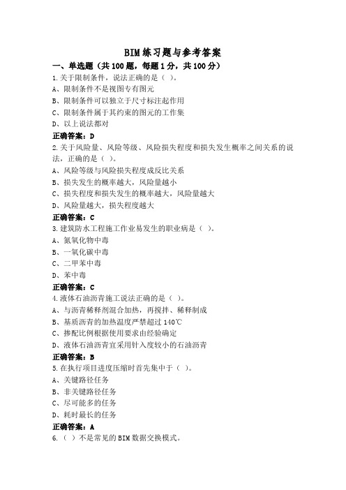
BIM练习题与参考答案一、单选题(共100题,每题1分,共100分)1.关于限制条件,说法正确的是()。
A、限制条件不是视图专有图元B、限制条件可以独立于尺寸标注起作用C、限制条件属于其约束的图元的工作集D、以上说法都对正确答案:D2.关于风险量、风险等级、风险损失程度和损失发生概率之间关系的说法,正确的是()。
A、风险等级与风险损失程度成反比关系B、损失发生的概率越大,风险量越小C、损失程度和损失发生的概率越大,风险量越大D、风险量越大,损失程度越大正确答案:C3.建筑防水工程施工作业易发生的职业病是()。
A、氮氧化物中毒B、一氧化碳中毒C、二甲苯中毒D、苯中毒正确答案:C4.液体石油沥青施工说法正确的是()。
A、与沥青稀释剂混合加热,再搅拌、稀释制成B、基质沥青的加热温度严禁超过140℃C、掺配比例根据使用要求由经验确定D、液体石油沥青宜采用针入度较小的石油沥青正确答案:B5.在执行项目进度压缩时首先集中于()。
A、关键路径任务B、非关键路径任务C、尽可能多的任务D、耗时最长的任务正确答案:A6.()不是常见的BIM数据交换模式。
A、IFC格式B、IFCXML格式C、COBIE格式D、CityGML格式正确答案:D7.下列配电装置的整定内容中,属于三相一次重合闸整定的是()整定。
A、电流元件B、方向元件C、同期角D、时间元件正确答案:C8.以下哪一项不属于BIM技术在工程进度管理上的应用()。
A、可视化的工程进度安排B、对工程建设过程的模拟C、对工程施工进度的调控D、对工程材料和设备供应过程的优化正确答案:C9.不属于“修剪/延伸”命令中的选项的是()。
A、修剪或延伸为线B、修剪或延伸多个图元C、修剪或延伸为角D、修剪或延伸一个图元正确答案:A10.建设单位对同一建设工程分项发包的必须依法()。
A、要求各承包方分别申领施工许可证B、分别取得施工许可证C、取得开工批准报告D、申领总施工许可证正确答案:B11.物料提升机安装至31m高度时,保证其整体稳定的方法是()。


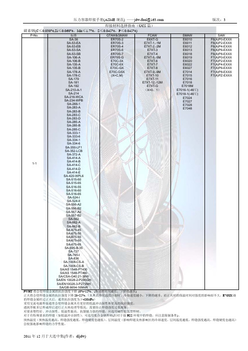
SPECIFICATION FOR SEAMLESS AND WELDED AUSTENITIC STAINLESS STEEL PIPESSA-312/SA-312M(Identical to ASTM Specification A312/A312M-95b except forclarified heat treatment requirements in5.2.2.)1.Scope1.1This specification covers seamless and straight-seam welded austenitic steel pipe intended for high-temperature and general corrosive service.NOTE1—When the impact test criterion for a low-temperature service would be15ft·lbf[20J]energy absorption or15mils[0.38 mm]lateral expansion,some of the austenitic stainless steel grades covered by this specification are accepted by certain pressure vesselor piping codes without the necessity of making the actual test.For example,Grades TP304,TP304L,and TP347are accepted by the ASME Pressure Vessel Code,Section VIII Division1,and by the Chemical Plant and Refinery Piping Code,ANSI B31.3,for serviceat temperatures as low as−425°F[−250°C]without qualification by impact tests.Other AISI stainless steel grades are usually acceptedfor service temperatures as low as−325°F[−200°C]without impact testing.Impact testing may,under certain circumstances,be required.For example,materials with chromium or nickel content outside the AISI ranges,and for material with carbon content exceeding0.10%,are required to be impact tested under the rules of ASME SectionVIII Division1when service temperatures are lower than−50°F[−45°C].1.2Grades TP304H,TP309H,TP309HCb,TP310H,TP310HCb,TP316H,TP321H,TP347H,and TP348Hare modifications of Grades TP304,TP309Cb,TP309S,TP310Cb,TP310S,TP316,TP321,TP347,and TP348, and are intended for high-temperature service.1.3Optional supplementary requirements are providedfor pipe where a greater degree of testing is desired. These supplementary requirements call for additional tests to be made and,when desired,one or more of these may be specified in the order.1.4Table X1.1lists the dimensions of welded and seamless stainless steel pipe as shown in ANSI B36.19. Pipe having other dimensions may be furnished provided such pipe complies with all other requirements of this specification.4771.5Grades TP321and TP321H have lower strength requirements for pipe manufactured by the seamless process in nominal wall thicknesses greater than3⁄8in.[9.5mm].1.6The values stated in either inch-pound units or SI units are to be regarded separately as standard. Within the text,the SI units are shown in brackets.The values stated in each system are not exact equivalents; therefore,each system must be used independently of the bining values from the two systems may result in nonconformance with the specification.The inch-pound units shall apply unless the“M”designation of this specification is specified in the order.NOTE2—The dimensionless designator NPS(nominal pipe size) has been substituted in this standard for such traditional terms as “nominal diameter,”“size,”and“nominal size.”2.Referenced Documents2.1ASTM Standards:A262Practices for Detecting Susceptibility to Intergran-ular Attack in Austenitic Stainless SteelsA370Test Methods and Definitions for Mechanical Test-ing of Steel ProductsA450/A450M Specification for General Requirements for Carbon,Ferritic Alloy,and Austenitic Alloy Steel TubesA530/A530M Specification for General Requirements for Specialized Carbon and Alloy Steel PipeE112Test Methods for Determining the Average Grain SizeE213Practice for Ultrasonic Examination of Metal Pipe and TubingSA-312/SA-312M1998SECTION IIE381Method of Macroetch Testing,Steel Bars,Billets, Blooms,and ForgingsE426Practice for Electromagnetic(Eddy-Current)Ex-amination of Seamless and Welded Tubular Products, Austenitic Stainless Steel,and Similar AlloysE527Practice for Numbering Metals and Alloys(UNS) 2.2ANSI Standards:B1.20.1Pipe Threads,General PurposeB36.10Welded and Seamless Wrought Steel PipeB36.19Stainless Steel Pipe2.3AWS Standard:A5.9Corrosion-Resisting Chromium and Chromium-Nickel Steel Welding Rods and Electrodes2.4Other Standard:SAE J1086Practice for Numbering Metals and Alloys (UNS)2.5Other Standard:SNT-TC-1A Personnel Qualification and Certification in Nondestructive Testing3.Ordering Information3.1Orders for material to this specification should include the following,as required,to describe the desired material adequately:3.1.1Quantity(feet,centimeters,or number of lengths),3.1.2Name of material(austenitic steel pipe),3.1.3Process(seamless or welded),3.1.4Grade(Table1),3.1.5Size(NPS or outside diameter and schedule number or average wall thickness),3.1.6Length(specific or random)(Section10),3.1.7Endfinish(Section on Ends of SpecificationA530/A530M),3.1.8Optional requirements(Section7),3.1.9Test report required(Certification Section of Specification A530/A530M),3.1.10Specification number,and3.1.11Special requirements or any supplementary requirements selected,or both.4784.General Requirements4.1Material furnished under this specification shall conform to the applicable requirements of the current edition of Specification A530/A530M unless otherwise provided herein.5.Materials and Manufacture5.1Manufacture:5.1.1The pipe shall be made by the seamless or an automatic welding process,with no addition offiller metal in the welding operation.5.1.2“Welded pipe NPS14and smaller shall havea single longitudinal weld.Welded pipe of a size larger than NPS14may be produced by forming and welding two longitudinal sections offlat stock when approved by the purchaser.All weld tests,examinations,inspections, or treatments are to be performed on each weld seam.”5.1.3At the manufacturer’s option,pipe may be either hotfinished or coldfinished.5.1.4The pipe shall be free of scale and contaminating iron particles.Pickling,blasting or surfacefinishing is not mandatory when pipe is bright annealed.The purchaser may request that a passivating treatment be applied.5.2Heat Treatment:5.2.1All pipe shall be furnished in the heat-treated condition in accordance with the requirements of Table 2.The heat-treatment procedure,except for“H”grades, S30815,S31272,S31254,S32654,N08367,and N08904 shall consist of heating the pipe to a minimum tempera-ture of1900°F[1040°C]and quenching in water or rapidly cooling by other means.5.2.2All H grades shall be furnished in the solution-treated condition.For H grades,separate solution heat treatments are required for solution annealing;in-process heat treatments are not permitted as a substitute for the separate solution annealing treatments.A solution anneal-ing temperature above1950°F[1065°C]may impair the resistance to intergranular corrosion after subsequent ex-posure to sensitizing conditions in TP309HCb, TP310HCb,TP321,TP321H,TP347,TP347H,TP348, and TP348H.When specified by the purchaser,a lower temperature stabilization or re-solution anneal shall be used subsequent to the initial high temperature solution anneal(see Supplementary Requirement S6).PART A—FERROUS MATERIAL SPECIFICATIONS SA-312/SA-312M5.3Grain Size:5.3.1The grain size of Grade UNS S32615,as determined in accordance with Test Methods E112, shall be No.3orfiner.5.3.2The grain size of TP309H,TP309HCb,TP310H and TP310HCb,as determined in accordance with Test Methods E112,shall be No.6or coarser.5.3.3The grain size of TP321H,as determinedin accordance with Test Methods E112,shall be No.7or coarser.6.Chemical Composition6.1The steel shall conform to the requirements asto chemical composition prescribed in Table1.7.Product Analysis7.1At the request of the purchaser,an analysis of one billet or one length offlat-rolled stock from each heat,or two pipes from each lot shall be made by the manufacturer.A lot of pipe shall consist of the following number of lengths of the same size and wall thickness from any one heat of steel:NPS Designator Lengths of Pipe in LotUnder2400or fraction thereof2to5200or fraction thereof6and over100or fraction thereof7.2The results of these analyses shall be reportedto the purchaser or the purchaser’s representative,and shall conform to the requirements specified in Section6. 7.3If the analysis of one of the tests specified in 7.1does not conform to the requirements specified in Section6,an analysis of each billet or pipe from the same heat or lot may be made,and all billets or pipe conforming to the requirements shall be accepted.8.Tensile Requirements8.1The tensile properties of the material shall con-form to the requirements prescribed in Table3.9.Mechanical Tests and Grain SizeDeterminations Required9.1Transverse or Longitudinal Tension Test—One tension test shall be made on a specimen for lots of479not more than100pipes.Tension tests shall be made on specimens from two tubes for lots of more than 100pipes.NOTE3—The term“lot,”for mechanical tests,applies to all pipe of the same diameter and wall thickness(or schedule)which are produced from the same heat of steel and subjected to the same finishing treatment:(1)in a continuous heat-treatment furnace,or (2)in a batch-type heat-treatment furnace,equipped with recording pyrometers and automatically controlled within a50°F[30°C]range, the larger of:(a)Each200ft[60m]or fraction thereof or,(b) That pipe heat treated in the same batch furnace charge.9.2Flattening Test—For material heat treated ina batch-type furnace,flattening tests shall be made on 5%of the pipe from each heat-treated lot.For material heat treated by the continuous process,this test shall be made on a sufficient number of pipe to constitute 5%of the lot,but in no case less than two lengths of pipe.9.2.1For welded pipe a transverse-guided face bend test of the weld may be conducted instead of a flattening test in accordance with the method outlined in the steel tubular product supplement of Test Methods and Definitions A370.The ductility of the weld shall be considered acceptable when there is no evidence of cracks in the weld or between the weld and the base metal after bending.Test specimens from5%of the lot shall be taken from the pipe or test plates of the same material as the pipe,the test plates being attached to the end of the cylinder and welded as a prolongation of the pipe longitudinal seam.9.3Hydrostatic Test—Each length offinished pipe shall be subjected to the hydrostatic test in accordance with Specification A530/A530M,unless specifically exempted under the provisions of9.4and9.5.9.4For pipe whose dimensions equal or exceed NPS 10,the purchaser with the agreement of the manufacturer may waive the hydrostatic test requirement when in lieu of such test the purchaser performs a system test. Each length of pipe furnished without the completed manufacturer’s hydrostatic test shall include with the mandatory markings the letters“NH.”9.5Nondestructive Examination:9.5.1As an alternative to the hydrostatic test,and when specified by the purchaser,each pipe shall be examined with a nondestructive test in accordance with Practice E213,or E426.Unless specifically called out by the purchaser,the selection of the nondestructive electric test will be at the option of the manufacturer. The range of pipe sizes that may be examined by each method shall be subject to the limitations in the scope of the respective practices.SA-312/SA-312M1998SECTION II9.5.2The following information is for the benefitof the user of this specification.9.5.2.1The reference standards defined in9.5.2.2 through9.5.2.5are convenient standards for calibrationof nondestructive testing equipment.The dimensionsof these standards should not be construed as the minimum size imperfection detectable by such equipment.9.5.2.2The ultrasonic testing(UT)can be per-formed to detect both longitudinally and circumferen-tially oriented defects.It should be recognized that different techniques should be employed to detect differ-ently oriented imperfections.The examination may not detect short,deep defects.9.5.2.3The eddy-current testing(ET)referencedin this specification,(Practice E426),has the capabilityof detecting significant discontinuities,especially the short abrupt type.9.5.2.4A purchaser interested in ascertainingthe nature(type,size,location,and orientation)of discontinuities that can be detected in the specific application of these examinations should discuss this with the manufacturer of the tubular product.9.5.3Time of Examination:9.5.3.1Nondestructive testing for specification acceptance shall be performed after all mechanical processing,heat treatments,and straightening opera-tions.This requirement does not preclude additional testing at earlier stages in the processing.9.5.4Surface Condition:9.5.4.1All surfaces shall be free of scale,dirt, grease,paint,or other foreign material that could inter-fere with interpretation of test results.The methods used for cleaning and preparing the surfaces for exami-nation shall not be detrimental to the base metal orthe surfacefinish.9.5.4.2Excessive surface roughness or deep scratches can produce signals that interfere with the test.9.5.5Extent of Examination:9.5.5.1The relative motion of the pipe and the transducer(s),coil(s),or sensor(s)shall be such thatthe entire pipe surface is scanned,except as in9.5.5.2.9.5.5.2The existence of end effects is recog-nized,and the extent of such effects shall be determinedby the manufacturer,and,if requested,shall be reportedto the purchaser.Other nondestructive tests may be480applied to the end areas,subject to agreement between the purchaser and the manufacturer.9.5.6Operator Qualifications:9.5.6.1The test unit operator shall be certified in accordance with SNT-TC-1A,or an equivalent recog-nized and documented standard.9.5.7Test Conditions:9.5.7.1For eddy-current testing,the excitation coil frequency shall be chosen to ensure adequate penetration yet provide good signal-to-noise-ratio.9.5.7.2The maximum eddy-current coil fre-quency used shall be as follows:On specified walls up to0.050in.-100KHz maxOn specified walls up to0.150in.-50KHz maxOn specified walls up to0.150in.-10KHz max9.5.7.3Ultrasonic-For examination by the ultra-sonic method,the minimum nominal transducer fre-quency shall be2.00MHz and the maximum nominal transducer size shall be1.5in.(a)If the equipment contains a reject noticefilter setting,this shall remain off during calibration and testing unless linearity can be demonstrated at that setting.9.5.8Reference Standards:9.5.8.1Reference standards of convenient length shall be prepared from a length of pipe of the same grade,size(NPS,or outside diameter and schedule or wall thickness),surfacefinish and heat treatment condi-tion as the pipe to be examined.9.5.8.2For Ultrasonic Testing,the reference ID and OD notches shall be any one of the three common notch shapes shown in Practice E213,at the option of the manufacturer.The depth of each notch shall not exceed121⁄2%of the specified nominal wall thickness of the pipe or0.004in.,whichever is greater.The width of the notch shall not exceed twice the depth. Notches shall be placed on both the OD and ID surfaces.9.5.8.3For Eddy-Current Testing,the reference standard shall contain,at the option of the manufacturer, any one of the following discontinuities:(a)Drilled Hole—The reference standard shall contain three or more holes,equally spaced circumferen-tially around the pipe and longitudinally separated by a sufficient distance to allow distinct identification of the signal from each hole.The holes shall be drilled radially and completely through the pipe wall,with care being taken to avoid distortion of the pipe whilePART A—FERROUS MATERIAL SPECIFICATIONS SA-312/SA-312Mdrilling.one hole shall be drilled in the weld,if visible. Alternately,the producer of welded pipe may chooseto drill one hole in the weld and run the calibration standard through the test coils three times with the weld turned at120deg.on each pass.The hole diameter shall vary with NPS as follows:NPS Designator Hole Diameter1⁄20.039in.(1mm)above1⁄2to1-1⁄40.055in.(1.4mm)above1-1⁄4to20.071in.(1.8mm)above2to50.087in.(2.2mm)above50.106in.(2.7mm)(b)Transverse Tangential Notch-Using a round toolorfile with a1⁄4in.(6.4mm)diameter,a notch shallbefiled or milled tangential to the surface and transverseto the longitudinal axis of the pipe.Said notch shall have a depth not exceeding12-1⁄2%of the specified nominal wall thickness of the pipe or0.004in.[0.102 mm],whichever is greater.(c)Longitudinal Notch-A notch0.031in.or less in width shall be machined in a radial plane parallel tothe tube axis on the outside surface of the pipe,to have a depth not exceeding12-1⁄2%of the specified wall thickness of the pipe or0.004in.,whichever is greater.The length of the notch shall be compatible with the testing method.9.5.8.4More or smaller reference discontinuities,or both,may be used by agreement between the pur-chaser and the manufacturer.9.5.9Standardization Procedure:9.5.9.1The test apparatus shall be standardizedat the beginning and end of each series of pipes ofthe same size(NPS or diameter and schedule or wall thickness),Grade and heat treatment condition,and at intervals not exceeding4h.More frequent standardiza-tion may be performed at the manufacturer’s optionor may be required upon agreement between the pur-chaser and the manufacturer.9.5.9.2The test apparatus shall also be standard-ized after any change in test system settings,changeof operator,equipment repair,or interruption due to power loss,process shutdown or when a problem is suspected.9.5.9.3The reference standard shall be passed through the test apparatus at the same speed and test system settings as the pipe to be tested.9.5.9.4The signal-to-noise ratio for the reference standard shall be2-1⁄2to1or greater.Extraneous signals caused by identifiable causes such as dings, scratches,dents,straightener marks,etc.,shall not be481considered noise.The rejection amplitude shall be ad-justed to be at least50%of full scale of the readout display.9.5.9.5If upon any standardization,the rejection amplitude has decreased by29%(3dB)of peak height from the last standardization,the pipe since the last calibration shall be rejected.The test system settings may be changed,or the transducer(s),coil(s)or sensor(s) adjusted,and the unit restandardized,but all pipe tested since the last acceptable standardization must be retested for acceptance.9.5.10Evaluation of Imperfections:9.5.10.1Pipes producing a signal equal to or greater than the lowest signal produced by the reference standard(s)shall be identified and separated from the acceptable pipes.The area producing the signal may be reexamined.9.5.10.2Such pipes shall be rejected if the test signal was produced by imperfections that cannot be identified or was produced by crack or crack-like imper-fections.These pipes may be repaired per Sections11 and12.To be accepted,a repaired pipe must pass the same non-destructive test by which it was rejected,and it must meet the minimum wall thickness requirements of this specification.9.5.10.3If the test signals were produced by visual imperfections such as:(a)Scratches;(b)Surface roughness;(c)Dings;(d)Straightener marks;(e)Cutting chips;(f)Steel die stamps;(g)Stop marks,or;(h)Pipe reducer ripple.The pipe may be accepted based on visual examina-tion provided the imperfection is less than0.004in.[0.1mm]or12-1⁄2%of the specified wall thickness (whichever is greater).9.5.10.4Rejected pipe may be reconditioned and retested providing the wall thickness is not decreased to less than that required by this or the product specifica-tion.The outside diameter at the point of grinding may be reduced by the amount so removed.To be accepted, retested pipe shall meet the test requirement.9.5.10.5If the imperfection is explored to the extent that it can be identified as non-rejectable,the pipe may be accepted without further test providingSA-312/SA-312M1998SECTION IIthe imperfection does not encroach on the minimum wall thickness.9.6Grain Size—Grain size determinations on gradesTP309H,TP309HCb,TP310H,TP310HCb,and UNSS32615shall be made on the same number of tubesas prescribed for theflattening test.10.Lengths10.1Pipe lengths shall be in accordance with the following regular practice:10.1.1Unless otherwise agreed upon,all sizes from NPS1⁄8to and including NPS8are available in a length upto24ft[Note4]with the permissible range of15to24ft [Note4].Short lengths are acceptable and the number and minimum length shall be agreed upon between the manu-facturer and the purchaser.NOTE4—This value(s)applies when the inch-pound designationof this specification is the basis of purchase.When the“M”designationof this specification is the basis of purchase,the corresponding metric value(s)shall be agreed upon between the manufacturer and the purchaser.10.1.2If definite cut lengths are desired,the lengths required shall be specified in the order.No pipe shallbe under the specified length and not more than1⁄4in. [6mm]over that specified.10.1.3No jointers are permitted unless otherwise specified.11.Workmanship,Finish,and Appearance11.1Thefinished pipes shall be reasonably straight and shall have a workmanlikefinish.Imperfections maybe removed by grinding,provided the wall thicknessesare not decreased to less than that permitted in Section8of Specification A530/A530M.12.Repair by Welding12.1For welded pipe whose diameter equals or exceeds NPS6,and whose nominal wall thickness equals or exceeds0.200,weld repairs made with the addition of compatiblefiller metal may be made tothe weld seam with the same procedures specified for plate defects in the section on Repair by Welding of Specification A530/A530M.12.2Weld repairs of the weld seam shall not exceed 20%of the seam length.48212.3Weld repairs shall be made only with the gas tungsten-arc welding process using the same classifica-tion of barefiller rod qualified to the most current AWS Specification A5.9as the grade of stainless steel pipe being repaired and as shown in Table4.12.4Pipes that have had weld seam repairs with filler metal shall be uniquely identified and shall be so stated and identified on the certificate of tests. 13.Certification13.1In addition to the information required by Specification A530/A530M,the certification shall state whether or not the material was hydrostatically tested.If the material was nondestructively tested,the certification shall so state and shall show which standard practice was followed and what reference discontinuities were used.14.Marking14.1In addition to the marking specified in Specifica-tion A530/A530M,the marking shall include the NPS(nominal pipe size)and schedule,heat numbering and NH when hydrotesting is not performed and ET when eddy-current testing is performed or UT when ultrasonic testing is performed.The marking shall also include the manufacturer’s private identifying mark,the marking requirement of9.4,if applicable,and whether seamless or welded.For Grades TP304H,TP316H, TP321H,TP347H,TP348H,and S30815,the marking shall also include the heat number and heat-treatment lot identification.If specified in the purchase order,the marking for pipe larger than NPS4shall include the weight.ernment Procurement15.1Scale Free Pipe for Government Procurement:15.1.1When specified in the contract or order, the following requirements shall be considered in the inquiry,contract or order,for agencies of the U.S. Government where scale free pipe or tube is required. These requirements shall take precedence if there is a conflict between these requirements and the product specifications.15.1.2The requirements of Specification A530/A 530M for pipe and Specification A450/A450M for tubes shall be applicable when pipe or tube is ordered to this specification.PART A—FERROUS MATERIAL SPECIFICATIONS SA-312/SA-312M15.1.3Pipe and tube shall be one of the following grades as specified herein:Grade UNS DesignationTP304S30400TP304L S30403TP304N S30451TP316S31600TP316L S31603TP316N S31651TP317S31700TP317L S31703TP321S32100TP347S3470015.1.4Part Number:Example:ASTM A312/A312M Pipe304NPS12 SCH40S SMLSSpecification Number.......................ASTM A312Pipe.....................................PGrade (304)NPS (12)Wall.....................................0.375SMLS OR WELDED.......................SML15.1.4.1Specification Number.......................ASTM A312Tube.....................................TGrade (304)Outside Diameter...........................0.250Wall.....................................0.035SMLS OR WELDED.......................WLD48315.1.5Ordering Information—Orders for material under this specification shall include the following in addition to the requirements of Section3:15.1.5.1Pipe or tube,15.1.5.2Part number,15.1.5.3Ultrasonic inspection,if required,15.1.5.4If shear wave test is to be conducted in two opposite circumferential directions,15.1.5.5Intergranular corrosion test,and15.1.5.6Level of preservation and packing re-quired.16.Keywords16.1austenitic stainless steel;seamless steel pipe; stainless steel pipe;steel pipe;welded steel pipe.SA-312/SA-312M1998SECTION IIT A B L E 1C H E M I C A L R E Q U I R E M E N T SC o m p o s i t i o n ,%U N S C a r b o n ,M a n g a n e s e C o l u m b i u m D e s i g n a t i o n m a x m a x P h o s p h o r u s ,S u l f u r ,p l u s T a n t a l u m ,N i t r o g e n G r a d e[N o t e (1)][N o t e (2)][N o t e (2)]m a x m a xS i l i c o n N i c k e l C h r o m i u m M o l y b d e n u m T i t a n i u m T a n t a l u m m a x [N o t e (3)]V a n a d i u mC o p p e r C e r i u m B o r o n A l u m i n u mT P 304S 304000.082.000.0400.0300.75m a x 8.00–11.018.0–20.0........................T P 304H S 304090.04–0.102.000.0400.0300.75m a x 8.00–11.018.0–20.0........................T P 304L S 304030.0352.000.0400.0300.75m a x 8.00–13.018.0–20.0........................[N o t e (5)]T P 304N S 304510.082.000.0400.0300.75m a x 8.00–11.018.0–20.0............0.10–0.16.........T P 304L N S 304530.0352.000.0400.0300.75m a x 8.00–11.018.0–20.0............0.10–0.16.........T P 309C b S 309400.082.000.0450.0300.75m a x 12.0–16.022.0–24.00.75m a x ...10×C ............m i n ,1.10m a x T P 309H S 309090.04–0.102.000.0400.0300.75m a x 12.0–15.022.0–24.0.....................T P 309H C b S 309410.04–0.102.000.0450.0300.75m a x 12.0–16.022.0–24.00.75m a x ...10×C .........m i n ,1.10m a x T P 309S S 309080.082.000.0450.0300.75m a x 12.0–15.022.0–24.00.75m a x ..................T P 310C b S 310400.082.000.0450.0300.75m a x 19.0–22.024.0–26.00.75m a x ...10×C ............m i n ,1.10m a x T P 310H S 310090.04–0.102.000.0400.0300.75m a x 19.0–22.024.0–26.0.....................T P 310H C b S 310410.04–0.102.000.0450.0300.75m a x 19.0–22.024.0–26.00.75m a x ...10×C .........m i n ,1.10m a x T P 310SS 310080.082.000.0450.0300.75m a x 19.0–22.024.0–26.00.75m a x ..................S 312720.08–0121.5–2.000.0300.0150.3–0.714.0–16.014.0–16.01.0–1.40.3–0.60.004–0.008T P 316S 316000.082.000.0400.0300.75m a x 11.0–14.016.0–18.02.00–3.00.....................[N o t e (4)]T P 316H S 316090.04–0.102.000.0400.0300.75m a x 11.0–14.016.0–18.02.00–3.00.....................[N o t e (4)]T P 316L S 316030.0352.000.0400.0300.75m a x 10.0–15.016.0–18.02.00–3.00.....................[N o t e (5)]T P 316N S 316510.082.000.0400.0300.75m a x 11.0–14.016.0–18.02.00–3.000.10–0.16.........[N o t e (4)]T P 316L N S 316530.0352.000.0400.0300.75m a x 11.0–14.016.0–18.02.00–3.00.........0.10–0.16.........[N o t e (4)]T P 317S 317000.082.000.0400.0300.75m a x 11.0–14.018.0–20.03.00–4.00.....................T P 317L S 317030.0352.000.0400.0300.75m a x 11.0–15.018.0–20.03.00–4.00.....................T P 321S 321000.082.000.0400.0300.75m a x 9.00–13.017.0–20.0...[N o t e (6)]..................T P 321H S 321090.04–0.102.000.0400.0300.75m a x 9.00–13.017.0–20.0...[N o t e (7)]..................T P 347S 347000.082.000.0400.0300.75m a x 9.00–13.017.0–20.0......[N o t e (8)]...............T P 347H S 347090.04–0.102.000.0400.0300.75m a x 9.00–13.017.0–20.0......[N o t e (9)]...............T P 347L N S 347510.005–2.000.0400.0300.75m a x 9.00–13.017.0–20.0......0.2–0.5...0.06–0.10...............0.020[N o t e (11)]T P 348S 348000.082.000.0400.0300.75m a x 9.00–13.017.0–20.0......[N o t e (8)]0.10............T P 348H S 348090.04–0.102.000.0400.0300.75m a x 9.00–13.017.0–20.0......[N o t e (9)]0.10............484。


CSAC-SA.45s原子钟测试——儒科测评报告测评概述:全球最小的芯片级原子钟CSAC—SA.45s现已经正式登陆中国,儒科电子对首批到货的CSAC进行了相关性能测试以期为客户选型提供依据。
本次测试,使用我们公司自主研制的高性能GPS同步时钟——TG100系统作为测试参考源,分别对CSAC的10MHz输出和1PPS相关指标进行了测试,并同其它铷钟进行了一个横向比较。
测试内容包括CSAC的10MHz的频率准确度、短期稳定性、相位噪声,以及1PPS信号的定时精度、锁定频率准确度、保持稳定性和24小时保持等关键指标。
此外,还对CSAC的锁定时间和功耗进行了测试。
测试设备:测试参考源:TG100-FTS同步时钟的10MHz输出以及1PPS秒脉冲;频率计数器:Agilent 53132A;相噪测试仪:Symmetricom TSC 5125A;万用表、直流电源设备。
待测设备:Symmetricom SA.45s芯片级原子钟。
测试连接:1.使用TG100同步时钟作为参考源(连续工作24小时以上)测试CSAC的1PPS和10MHz输出;2.使用屋顶天线,收星状况良好。
图表1 测试连接测试综述:CSAC 的各项指标测试良好; ☆锁定时间约为:60s ;☆开机功耗约为:110mW ,稳定运行时功耗约为:90mW ; ☆10MHz 输出的相噪、短稳、频率准确度和普通铷钟水平相当; ☆1PPS 锁定输出峰峰值实测67小时保持在20ns 以内; ☆1PPS 锁定67小时平均频率准确度为:2.32E-14; ☆1PPS 保持24小时相差为:4us ;☆1PPS 保持24小时平均频率准确度为:4.72E-11。
测试项目:一、开机锁定时间原子钟型号锁定时间CSAC原子钟约60sSA.3xm系列铷钟约5分钟X72系列铷钟约6分钟图表 2 开机锁定时间对比二、开机功耗原子钟型号开机功耗稳定运行时功耗CSAC原子钟110 mW 90m WSA.3xm系列14 W 5 WX72系列18 W(最大)10 W图表 3 功耗对比注明:测试的时候要求测试环境的温度在25℃左右三、10MHz方波输出1.频率准确度图表 4 频率准确度2.相位噪声图表 5 相位噪声CSAC锁定时候的10MHz频率准确度可以达到E-10量级CSAC的10MHz输出的相噪与普通铷钟SA.31m性能相当相位噪声(10MHz)SA.31m CSAC实测结果@1Hz<-65dBc/Hz <-64.54dBc/Hz@10Hz <-85dBc/Hz <-93.75dBc/Hz@100Hz<-112dBc/Hz <-120.67dBc/Hz@1KHz<-130dBc/Hz <-132.79dBc/Hz@10KHz <-140dBc/hz <-140.43dBc/Hz图表 6 相噪对比3.短期稳定性CSAC的短期稳定性与普通铷钟SA.31m的性能相当图表 7 阿伦方差10MHz输出短期稳定性SA.31m CSAC实测结果@1S ≤5E-11 5.31E-11@10S ≤2.5E-11 1.96E-11@100S ≤1E-11 7.90E-12图表 8 短稳对比四、1PPS相关指标1.1PPS定时精度(锁定到GPS)1PPS输出峰峰值实测67小时保持在20ns以内图表 9 锁定PPS精度1PPS定时精度测试数据采集从CSAC刚开始锁定到外部1PPS时进行记录。

jumpserver1.5.9安装##jumpserver 1.5.9安装#!/bin/bash###jumpserver 1.5.9systemctl stop firewalldsystemctl disable firewalldsetenforce 0sed -i "s/SELINUX=.*/SELINUX=disabled/g" /etc/selinux/confighostnamectl set-hostname node$(hostname -I |cut -d '.' -f4)#@准备Python3和python虚拟环境#安装依赖包yum -y install wget gcc git epel-release#安装Python3.6yum -y install python36 python36-devel#安装redisyum -y install redissystemctl enable redissystemctl start redis#安装mariadbyum -y install mariadb mariadb-devel mariadb-server mariadb-sharedsystemctl enable mariadbsystemctl start mariadb#创建数据看看jumpserver并授权mysql -e "create database if not exists jumpserver default charset 'utf8';grant all on jumpserver.* TO 'jumpserver'@'localhost' IDENTIFIED BY 'jumpserver';flush privileges;"mysql -ujumpserver -pjumpserver -e 'show databases;'#建⽴Python虚拟环境python3.6 -m venv /opt/py3source /opt/py3/bin/activatewget http://134.175.107.119/download/jumpserver/1.5.9/jumpserver.tar.gztar zxvf jumpserver.tar.gz -C /opt/####安装编译环境依赖cd /opt/jumpserver/requirements#安装依赖rpm包yum install -y $(cat rpm_requirements.txt)#安装Python库依赖pip install wheel && \pip install --upgrade pip setuptools && \pip install -r requirements.txt#确保已经载⼊ py3 虚拟环境, 中间如果遇到报错⼀般是依赖包没装全, 可以通过搜索引擎解决#国内可以使⽤镜像加速##pip install wheel -i https:///pypi/simple/#pip install --upgrade pip setuptools -i https:///pypi/simple/#pip install -r requirements.txt -i https:///pypi/simple/##修改配置⽂件cd /opt/jumpserver\cp config_example.yml config.ymlSECRET_KEY=`cat /dev/urandom | tr -dc A-Za-z0-9 | head -c 50`echo"SECRET_KEY=$SECRET_KEY" >> ~/.bashrcBOOTSTRAP_TOKEN=`cat /dev/urandom | tr -dc A-Za-z0-9 | head -c 16`echo"BOOTSTRAP_TOKEN=$BOOTSTRAP_TOKEN" >> ~/.bashrcsed -i "s/SECRET_KEY:/SECRET_KEY: $SECRET_KEY/g" /opt/jumpserver/config.ymlsed -i "s/BOOTSTRAP_TOKEN:/BOOTSTRAP_TOKEN: $BOOTSTRAP_TOKEN/g" /opt/jumpserver/config.ymlsed -i "s/# DEBUG: true/DEBUG: false/g" /opt/jumpserver/config.ymlsed -i "s/# LOG_LEVEL: DEBUG/LOG_LEVEL: ERROR/g" /opt/jumpserver/config.ymlsed -i "s/# SESSION_EXPIRE_AT_BROWSER_CLOSE: false/SESSION_EXPIRE_AT_BROWSER_CLOSE: true/g" /opt/jumpserver/config.yml####数据库密码jumpserversed -i 's/DB_PASSWORD:.*/DB_PASSWORD: jumpserver/g' /opt/jumpserver/config.ymlecho -e "\033[31m 你的SECRET_KEY是 $SECRET_KEY \033[0m"echo -e "\033[31m 你的BOOTSTRAP_TOKEN是 $BOOTSTRAP_TOKEN \033[0m"##echo -e "\033[31m 你的SECRET_KEY是 $SECRET_KEY \033[0m"## 你的SECRET_KEY是 jZIfxus6Admhip2vsuOzAEqh3byK5jUx6KOc0hNYaNZSvFjiJW##(py3) [root@node70 jumpserver]# echo -e "\033[31m 你的BOOTSTRAP_TOKEN是 $BOOTSTRAP_TOKEN \033[0m"## 你的BOOTSTRAP_TOKEN是 wv5gsAwJdTJOSCab###启动 jumpserver 要在后台运⾏加 ./jms start -dsource /opt/py3/bin/activate && cd /opt/jumpserver && ./jms start##正常部署 koko 组件cd /opt#wget http://134.175.107.119/download/koko/1.5.9/koko-master-linux-amd64.tar.gzwget https:///jumpserver/koko/releases/download/1.5.9/koko-master-linux-amd64.tar.gztar -zxvf koko-master-linux-amd64.tar.gz -C /opt/chown -R root:root /opt/kokodircd /opt/kokodir\cp config_example.yml config.ymlsed -i "s/BOOTSTRAP_TOKEN:.*/BOOTSTRAP_TOKEN: $BOOTSTRAP_TOKEN/g" /opt/kokodir/config.ymlsed -i "s/# LOG_LEVEL:.*/LOG_LEVEL: ERROR/" /opt/kokodir/config.ymlsed -i "s/# SHARE_ROOM_TYPE:.*/SHARE_ROOM_TYPE: redis/" /opt/kokodir/config.yml### Redis配置sed -i "s/# REDIS_HOST:.*/REDIS_HOST: 127.0.0.1/" /opt/kokodir/config.ymlsed -i "s/# REDIS_PORT:.*/REDIS_PORT: 6379/" /opt/kokodir/config.yml#sed -i "s/# REDIS_PASSWORD:.*/REDIS_PASSWORD: ZhYnLrodpmPncovxJTnRyiBs/" /opt/kokodir/config.ymlsed -i "s/# REDIS_DB_ROOM:.*/REDIS_DB_ROOM: 6/" /opt/kokodir/config.ymlgrep -Ev '^$|^#' /opt/kokodir/config.yml###启动 koko 要在后台运⾏加 ./koko -dsource /opt/py3/bin/activate && cd /opt/kokodir && ./koko##docker 部署 koko 组件如果前⾯已经正常部署了 koko, 可以跳过此步骤#docker run --name jms_koko -d -p 2222:2222 -p 127.0.0.1:5000:5000 -e CORE_HOST=http://192.168.244.144:8080 -e BOOTSTRAP_TOKEN=zxffNymGjP79j6BN -e LOG_LEVEL=ERROR --restart=always jumpserver/jm###正常安装并启动 guacamole 组件#根据 guacamole官⽅⽂档⽂档安装对应的依赖包###Fedora/CentOS/RHEL:yum -y localinstall --nogpgcheck https:///rpmfusion/free/el/rpmfusion-free-release-7.noarch.rpm https:///rpmfusion/nonfree/el/rpmfusion-nonfree-release-7.noarch.rpm && \yum install -y cairo-devel libjpeg-turbo-devel libpng-devel uuid-devel && \yum install -y ffmpeg-devel freerdp1.2-devel pango-devel libssh2-devel libtelnet-devel libvncserver-devel pulseaudio-libs-devel openssl-devel libvorbis-devel libwebp-devel && \ln -s /usr/local/lib/freerdp /usr/lib64/freerdp##############automake-1.15wget /gnu/automake/automake-1.15.tar.gztar -zxvf automake-1.15.tar.gz -C /opt/cd /opt/automake-1.15./bootstrap.sh./configure && make && make installautomake --version#############################yum install -y libtool##正常安装并启动 guacamole 组件cd /optgit clone --depth=1 https:///jumpserver/docker-guacamole.gitcd /opt/docker-guacamole && \tar -xf guacamole-server-1.0.0.tar.gz && \tar -xf ssh-forward.tar.gz -C /bin/ && \chmod +x /bin/ssh-forwardcd /opt/docker-guacamole/guacamole-server-1.0.0autoreconf -fi && ./configure --with-init-dir=/etc/init.d && make && make install#################需要先在当前环境配置好 java#Centos:yum install -y java-1.8.0-openjdk java-1.8.0-openjdk-develmkdir -p /config/guacamole /config/guacamole/extensions /config/guacamole/record /config/guacamole/drive && \chown daemon:daemon /config/guacamole/record /config/guacamole/drive && \cd /config############################wget /apache/tomcat/tomcat-9/v9.0.35/bin/apache-tomcat-9.0.35.tar.gztar -xf apache-tomcat-9.0.35.tar.gz && \mv apache-tomcat-9.0.35 tomcat9 && \rm -rf /config/tomcat9/webapps/* && \sed -i 's/Connector port="8080"/Connector port="8081"/g' /config/tomcat9/conf/server.xml && \echo "java.util.logging.ConsoleHandler.encoding = UTF-8" >> /config/tomcat9/conf/logging.properties && \ln -sf /opt/docker-guacamole/guacamole-1.0.0.war /config/tomcat9/webapps/ROOT.war && \ln -sf /opt/docker-guacamole/guacamole-auth-jumpserver-1.0.0.jar /config/guacamole/extensions/guacamole-auth-jumpserver-1.0.0.jar && \ln -sf /opt/docker-guacamole/root/app/guacamole/guacamole.properties /config/guacamole/guacamole.properties##设置 guacamole 环境export JUMPSERVER_SERVER=http://127.0.0.1:8080echo "export JUMPSERVER_SERVER=http://127.0.0.1:8080" >> ~/.bashrcexport BOOTSTRAP_TOKEN=zxffNymGjP79j6BNecho "export BOOTSTRAP_TOKEN=zxffNymGjP79j6BN" >> ~/.bashrcexport JUMPSERVER_KEY_DIR=/config/guacamole/keysecho "export JUMPSERVER_KEY_DIR=/config/guacamole/keys" >> ~/.bashrcexport GUACAMOLE_HOME=/config/guacamoleecho "export GUACAMOLE_HOME=/config/guacamole" >> ~/.bashrcexport GUACAMOLE_LOG_LEVEL=ERRORecho "export GUACAMOLE_LOG_LEVEL=ERROR" >> ~/.bashrcexport JUMPSERVER_ENABLE_DRIVE=trueecho "export JUMPSERVER_ENABLE_DRIVE=true" >> ~/.bashrc####环境变量说明###JUMPSERVER_SERVER 指 core 访问地址###BOOTSTRAP_TOKEN 为 Jumpserver/config.yml ⾥⾯的 BOOTSTRAP_TOKEN 值###JUMPSERVER_KEY_DIR 认证成功后 key 存放⽬录###GUACAMOLE_HOME 为 guacamole.properties 配置⽂件所在⽬录###GUACAMOLE_LOG_LEVEL 为⽣成⽇志的等级###JUMPSERVER_ENABLE_DRIVE 为 rdp 协议挂载共享盘###启动 guacamole/etc/init.d/guacd startsh /config/tomcat9/bin/startup.sh#####docker 部署 guacamole 组件###如果前⾯已经正常部署了 guacamole, 可以跳过此步骤##docker run --name jms_guacamole -d \## -p 127.0.0.1:8081:8080 \## -e JUMPSERVER_SERVER=http://<Jumpserver_url> \## -e BOOTSTRAP_TOKEN=<Jumpserver_BOOTSTRAP_TOKEN> \## -e GUACAMOLE_LOG_LEVEL=ERROR \## jumpserver/jms_guacamole:<Tag>##<Jumpserver_url> 为 jumpserver 的 url 地址, <Jumpserver_BOOTSTRAP_TOKEN> 需要从 jumpserver/config.yml ⾥⾯获取, 保证⼀致, <Tag> 是版本##例:#docker run --name jms_guacamole -d -p 127.0.0.1:8081:8080 -e JUMPSERVER_SERVER=http://192.168.244.144:8080 -e BOOTSTRAP_TOKEN=abcdefg1234 -e GUACAMOLE_LOG_LEVEL=ERROR jumpserver/jms_g ####下载 luna 组件cd /optwget http://134.175.107.119/download/luna/1.5.9/luna.tar.gz##wget https:///jumpserver/luna/releases/download/1.5.9/luna.tar.gztar -xf luna.tar.gzchown -R nginx:nginx luna#####nginxyum install -y yum-utilsecho '[nginx-stable]name=nginx stable repobaseurl=/packages/centos/$releasever/$basearch/gpgcheck=1enabled=1gpgkey=https:///keys/nginx_signing.keymodule_hotfixes=true[nginx-mainline]name=nginx mainline repobaseurl=/packages/mainline/centos/$releasever/$basearch/ gpgcheck=1enabled=0gpgkey=https:///keys/nginx_signing.keymodule_hotfixes=true' >/etc/yum.repos.d/nginx.repoyum install -y nginx\cp /etc/nginx/conf.d/default.conf{,.bak}echo >/etc/nginx/conf.d/default.confecho 'server {listen 80;client_max_body_size 100m; # 录像及⽂件上传⼤⼩限制location /luna/ {try_files $uri / /index.html;alias /opt/luna/; # luna 路径, 如果修改安装⽬录, 此处需要修改}location /media/ {add_header Content-Encoding gzip;root /opt/jumpserver/data/; # 录像位置, 如果修改安装⽬录, 此处需要修改 }location /static/ {root /opt/jumpserver/data/; # 静态资源, 如果修改安装⽬录, 此处需要修改 }location /koko/ {proxy_pass http://localhost:5000;proxy_buffering off;proxy_http_version 1.1;proxy_set_header Upgrade $http_upgrade;proxy_set_header Connection "upgrade";proxy_set_header X-Real-IP $remote_addr;proxy_set_header Host $host;proxy_set_header X-Forwarded-For $proxy_add_x_forwarded_for;access_log off;}location /guacamole/ {proxy_pass http://localhost:8081/;proxy_buffering off;proxy_http_version 1.1;proxy_set_header Upgrade $http_upgrade;proxy_set_header Connection $http_connection;proxy_set_header X-Real-IP $remote_addr;proxy_set_header Host $host;proxy_set_header X-Forwarded-For $proxy_add_x_forwarded_for;access_log off;}location /ws/ {proxy_set_header X-Real-IP $remote_addr;proxy_set_header Host $host;proxy_set_header X-Forwarded-For $proxy_add_x_forwarded_for;proxy_pass http://localhost:8070;proxy_http_version 1.1;proxy_buffering off;proxy_set_header Upgrade $http_upgrade;proxy_set_header Connection "upgrade";}location / {proxy_pass http://localhost:8080;proxy_set_header X-Real-IP $remote_addr;proxy_set_header Host $host;proxy_set_header X-Forwarded-For $proxy_add_x_forwarded_for;}}' >/etc/nginx/conf.d/jumpserver.confnginx -tsystemctl start nginx.service。

SA.3Xm铷原子振荡器
产品概述
SA.3Xm是业界最小的一款铷原子振荡器,该振荡器的尺寸与目前流行的50x50恒温晶振一样大,引脚也充分考虑与恒温晶振的引脚定义兼容,用户在可以不考虑引脚和尺寸的情况下轻松升级到铷原子振荡器。
西安同步电子科技有限公司代理的SA.3Xm得到广大用户的信任与支持,我们会再接再厉做好技术支持工作。
产品功能
1)提供一路标准的10MHz正弦信号;
2)同步的1 PPS输入/输出;
3)RS-232管理控制接口。
产品特点
a)高精度铷原子振荡器;
b)超小型封装:51mm*51mm;
c)标准石英振荡器引脚;
d)低功率损耗。
典型应用
1)本产品适用于CDMA,WCDMA,TD-SCDMA等远程无人值守基站或移动式基站等多
种通信应用;
2)DVB或wimax等对于价格和指标要求较高的领域;
3)适用于各种电信、传输应用。
技术指标
安装尺寸:。

Arbitrary Function GeneratorsAFG31000 Series DatasheetThe Tektronix AFG31000 Series is a high-performance AFG with built-in arbitrary waveform generation, real-time waveform monitoring, and the largest touchscreen on the market. Providing advanced waveform generation and programming capabilities, waveform verification, and a modern touch-screen interface, the new AFG31000 is sure to delight and simplify the job of every researcher and engineer.Key performance specifications1 or2 channel modelsOutput amplitude range 1 mV P-P to 10 V P-Pinto 50 Ω loadsBasic (AFG) mode:25 MHz, 50 MHz, 100 MHz, 150 MHz, or 250 MHz sine waveforms250 MSa/s, 1 GSa/s or 2 GSa/s sample rates14-bit vertical resolutionBuilt-in waveforms include sine, square, ramp, pulse, noise, andother frequently used waveformsSweep, Burst, and Modulation modes (AM, FM, PM, FSK, andPWM)Advanced (Sequence) mode:Continuous mode (optional Sequence, Triggered and Gatedmodes)16 Mpts arbitrary waveform memory on each channel (128 Mptsoptional)Up to 256 steps in sequence mode with loop, jump and wait events Variable sampling clock 1 µSa/s to 2 GSa/sKey featuresPatented InstaView ™ technology enables engineers to see the actual waveform at the Device Under Test (DUT) in real time, without the need of an oscilloscope and probe, eliminating the uncertainty causedby mismatched impedanceSequencing option adds the ability to program long, complexwaveforms with up to 256 stepsThe 9-inch capacitive touch screen works like a smart phone and hasshort-cuts to frequently used settingsBuilt-in ArbBuilder lets you create and edit arbitrary waveforms on theinstrument, eliminating the need to connect to a PCOutputs are protected from over voltage and current to minimizepotential instrument damageCompatible with TekBench ™ software to help students set up, control,and analyze test results in the labApplicationsAdvanced researchClock and system synchronizationReplication of real world signalsComponent and circuit characterization and validationEmbedded circuit design and testGeneral purpose signal generationBasic and Advanced ModesThe AFG31000 series is the industry’s first arbitrary function generator with full function Basic (AFG) and Advanced (Sequence) modes.In Basic mode, the AFG31000 generates traditional functions and arbitrary waveforms. The touchscreen and front-panel controls make it simple to set up.Basic mode lets you change frequency without the need to worry about waveform length and sample rate. This feature is useful in analog designs that characterize filter/amplifier frequency responses or in digital designs where clock rates change frequently.Key settings are visible at a glance, and are easy to adjust using touch, numeric keypad, or rotary controlsNew with the AFG31000, Advanced mode provides the ability to generate multiple waveforms with complex timing. In this mode, you can compose a list (or a sequence) of 1 to 256 waveforms, with total waveform length up to 16 Mpts/ch (128 Mpts/ch optional) and define the ouput sequence of these waveforms. Repeat, go-to, wait, jump, and triggered events are all supported and the large memory provides space to store many waveforms or long waveforms.This feature is very useful in applications where many test cases need to be performed sequentially. Instead of loading the test cases one by one, you can put all of them in a sequence and load at one time, switching from one to another seamlessly to greatly improve the test efficiency.Advanced mode lets you build complex waveform sequences with flexible step controlsSequenced sine waveforms with different frequency and amplitude. Additionally, Advanced mode uses variable sample rate technology. Every sample in a waveform is output once and only once in each cycle, synchronized to the sample rate. Since there is no skipping or repetition, all details in the waveforms are kept. This feature is very useful for applications in which signal fidelity is extremely critical, such as IQ modulation and pulse train generation.InstaView™ technology shows the actual waveform at the DUTMost waveform generators assume they are driving a 50 Ω impedance. However, most devices under test do not have a 50 Ω impedance. This mismatch results in an inconsistency between the waveform as set on the AFG and the signal at the DUT.DatasheetWith InstaView turned off, the AFG31000 works like a traditional function generator. Due to an impedance mismatch, the AFG display shows a different waveform from the one observed at the DUT.With the patented InstaView ™technology, the AFG31000 Series can display the actual waveform at the DUT, instead of just the nominalwaveform as set on the AFG. The waveform displayed on the AFG instantly responds to changes in frequency, amplitude, waveform shape, andimpedance changes at the DUT. InstaView helps eliminate the uncertainty and measurement risk caused by impedance mismatches, without requiringadditional cables, instruments, or effort.With InstaView turned on, the AFG31000 shows the waveform as observed at the DUT.A large touch screen and smart user interfaceThe large 9-inch capacitive touch screen displays all related settings and parameters on a single screen. Similar to smart devices, you can tap or swipe to easily select, browse, locate and change settings and parameters.Frequently-used functions are immediately accessible. Familiar buttons and rotary knob controls are available for more traditional navigation.Frequently used settings are easy to access from the swipe-up menuAFG31000 SeriesBuilt-in ArbBuilder tool makes creating and editing arbitrary waveforms easier than ever In the past, you needed a PC with waveform editing software to create or edit your arbitrary waveforms. The waveform would then need to be downloaded to the AFG using either a USB stick or a data cable connection. The process was time-consuming, especially when waveforms required frequent changes.ArbBuilder is a built-in application on the AFG31000 series that lets you create and edit your arbitrary waveforms directly on the generator. You can create arbitrary waveforms with the Equation Editor tool or start from a library of standard templates. Thanks to the large capacitive touch screen, you can drag, pinch and zoom to get the detail you need.You can quickly replicate real-world waveforms captured with oscilloscopes or created by third-party software by loading CSV format data files directly into ArbBuilder from a USB memory stick.Creating an arbitrary waveform using the easy touch screen interfaceSimplified multi-unit synchronizationMost applications need one or two channels of output, but some applications require more channels. For example, in order to simulate 3-phase power signals, engineers often need to synchronize three 2-channel generators; one for the voltage and current on each phase. To do this used to be time-consuming, as it required many cable connections between the AFG units, and making changes in deep branches of the menu trees on all instruments.The AFG31000 simplifies this process with an onscreen wizard that leads you through the process of making cable connections and configuring settings to synchronize multiple generators.An on-screen wizard guides you through the process of multiple-unit synchronizationUpgradability protects your investmentThe AFG31000 provides upgrade options for bandwidth, memory extension, and sequence mode support. These options can be installed at the factory or at any time after purchase. This upgradability helps to reduce the product ownership threshold. And when your test requirements change, you can purchase and install upgrade software licenses to add higher performance features. Upgrades eliminate the concern about the return on investment during the instrument lifetime.DatasheetAFG31000 SeriesSpecificationsAll specifications are guaranteed unless noted otherwise. All specifications apply to all models unless noted otherwise.Model overviewOutput characteristicsAmplitudeOutput impedance50 ΩLoad impedance setting Selectable: 50 Ω, 1 Ω to 10.0 kΩ, High Z (Adjusts displayed amplitude according to selected load impedance)Isolation42 Vpk maximum to earth groundShort-circuit protection Signal outputs are robust against permanent shorts against floating groundOvercurrent protection When incoming current is greater than 250 mA, the output channels are protected with relays that disconnect the AFG from thedevice under test. Connection can be resumed by user after removing the incoming currentGeneral characteristics - Basic modeBasic (AFG)Run modes Continuous, Modulation, Sweep and BurstStandard waveforms Sine, Square, Pulse, Ramp, More (Noise, DC,Sin(x)/x, Gaussian, Lorentz, Exponential Rise, Exponential Decay, Haversine )Arbitrary waveformsSampling clock: 250 MSa/s, 1 GSa/s or 2 GSa/s (model and waveform length apply)Vertical resolution: 14 bitsWaveform length: 2 to 131,072 pointsSineFrequency rangeEffective maximum frequency outAmplitude flatness (1 V P-P ,relative to 1 kHz)Amplitude flatness (1 V P-P ,relative to 1 kHz), typicalHarmonic distortion (1 V P-P ),typicalDatasheetTHD, typical≤ 0.04%, 10 Hz to 20 kHz, 1 V P-PSpurious noise (1 V P-P ), typicalPhase noise, typical< -125 dBc/Hz at 20 MHz, 10 kHz offset, 1 V P-PResidual clock noise, all models -63 dBmSquareFrequency rangeRise/fall time, typicalOvershoot, typical< 3%Jitter (RMS), typical2.5 psRampFrequency rangeLinearity, typical (1 kHz, 1 V P-P ,100% symmetry)Symmetry0% to 100%AFG31000 SeriesGeneral characteristics - Basic modePulseFrequency rangePulse widthPulse width resolution 10 ps or 5 digitsPulse Duty 0.001% to 99.999% (limitations of pulse width apply)Edge transition timeEdge transition time resolution 10 ps or 4 digits Lead delay rangeLead delay resolution 10 ps or 8 digits Overshoot, typical < 2%Jitter (RMS), typical 2.5 psDCRange (into 50 Ω)Resolution (into 50 Ω) 1 mV or 4 digits Accuracy ± (1% of |setting | +1mV)NoiseBandwidth (-3 dB)Noise typeWhite GaussianInternal noiseDatasheetGeneral characteristics - Basic modeOther waveformsFrequency rangeArbitrary waveformsFrequency rangeEffective analog bandwidth (-3 dB)Waveform length2 to 131,072Sample rateVertical resolution14 bitRise/fall time, typicalJitter (RMS), typical2.5 psModulationAM, FM, PMAM modulation depth0.0 % to 120 %AM modulation resolution0.1%AFG31000 SeriesGeneral characteristics - Basic modeMinimum FM peak deviationDCMaximum FM peak deviationPM phase deviation range0° to 180°PM phase resolution0.1°FSKPWMSweepType Linear, Logarithmic Waveforms All, except Pulse, Noise, DC Sweep time 1 ms to 500 s Hold/return time0 s to 500 s Maximum total sweep time500 sAccuracy, typical: ≤ 0.4%Minimum start/stop frequency All except ARB: 1 μHzARB: 1 mHzMaximum start/stop frequencyDatasheetGeneral characteristics - Basic modeBurstWaveform All except Noise, DC Type Triggered, gatedBurst count 1 to 1,000,000 cycles or Infinite Intenal trigger rate 1 μs to 500.0 sGate and trigger sources Internal, external, remote interfaceInstaView ™Waveforms All except noise Cable (channel output to load)50 Ω BNC to BNCRun modeContinuous in Basic modeMaximum measurement range (DC + peak AC voltage)DC level measurementAmplitude measurementBandwidth (-3 dB)500 MHzFlatness, sine, 1 V P-P , into 50 ohm, relative to 1 kHz,typicalCable propagation delay measurement, typicalAFG31000 SeriesGeneral characteristics - Basic modeGeneral characteristics - Advanced modeWaveform memory size 16 Mpts (128 Mpts optional) each channel Run modeStandard: ContinuousOptional: Sequence, Triggered, GatedNumber of waveform entriesContinuous, Triggered, Gated: 1 Sequence: 1 to 256Minimum waveform length 168 pts Waveform granularity 1 pt Vertical resolution 14 bitsJump/trigger events External trigger (rising or falling edge), manual trigger, timer, SCPI commands Repeat count 1 to 1,000,000 or infinite Timer range 2 µS to 3600 S Timer resolution 4 ns or 8 digitsVariable sample rateRise/Fall time, typicalOvershoot, typical< 2%Level flatness, typical (sine, 1 V P-P ,relative to 1 kHz)Harmonic distortion, typical (sine with 64 pts/cycle, 1 V P-P )DatasheetSpurious, typical (sine with 64 pts/cycle, 1 V P-P )Spurious free dynamic range,typical (sine with 64 pts/cycle,1 V P-P )Phase noise, typical (sine with 64 pts/cycle, 1 V P-P , at 10 kHz offset)Skew controlRange -320 ns to 320 ns (channel 1 to channel 2 on dual channel models, at maximum sample rate)Resolution 100 ps or 4 digits Accuracy, typical ±(1% of |setting| + 500 ps)Initial skew, typical< 500 psSystem characteristicsOutput Frequency ResolutionFrequency accuracy±10-6 of setting (all except ARB), 0 °C to 50 °C (32 °F to 122 °F)±10-6 of setting ± 1 μHz (ARB), 0 °C to 50 °C (32 °F to 122 °F)Aging ±1.0 x 10⁻⁶ per yearPhaseRange -180° to +180°Resolution0.01° (sine)0.1° (other waveforms)Remote program interface GPIB, Ethernet 10BASE-T / 100BASE-TX / 1000BASE-T, USB 2.0Maximum configuration times,typicalPower sourceSource100-240 V, 47-63 Hz 115 V, 360-440 HzConsumption120 WAFG31000 SeriesGeneral characteristics - Advanced modeWarm up time, typical 20 minutes minimum Power on self diagnosis time < 24 s Acoustic noise < 50 dBADisplay9-inch capacitive touch screen with 800 * 480 resolutionUser interface and Help languages English, French, German, Japanese, Korean, Simplified and Traditional Chinese, Russian (user selectable)Auxiliary input characteristicsExternal modulation input, channel 1 and channel 2Input rangeInput impedance 5.2 kΩFrequency range 125 kHz (1 MSa/s)External Trigger inputLevel TTL compatible Impedance10 kΩMinimum pulse width 100 nsSlopePositive or negative selectable Trigger delay range 0 ns to 85 s Trigger delay resolution 100 ps or 5 digitsTrigger latency, typical 390 ns (trigger input to signal output)Jitter (RMS), typical 100 ps (signal output, with external trigger input in burst mode)10 MHz reference clock inputImpedance 1 kΩInput couplingACRequired input voltage swing 100 mV P-P to 5 V P-P Lock range10 MHz ±35 kHz Channel 1 external add inputImpedance 50 ΩInput range -1 V to +1 V (DC + peak AC)BandwidthDC to 10 MHz (-3 dB) at 1 V P-P DatasheetSystem characteristicsAFG31000 Series Auxiliary output characteristicsChannel 1 trigger outputLevel Positive TTL level pulse into 1 kΩImpedance50 ΩJitter, RMS, typical10 ps for all modelsOutput frequency10 MHz reference clock outImpedance50 Ω, AC coupledAmplitude 1.2 V P-P into 50 Ω loadPhysical characteristicsDimensionsHeight191.8 mm (7.55 in.)Width412.8 mm (16.25 in.)Depth143.3 mm (5.64 in.)WeightNet 4.7 kg (10.4 lb.)Shipping7.0 kg (15.4 lb.)EMC, environment, and safetyTemperatureOperating0 °C to +50 °C (32 °F to 122 °F)Nonoperating-30 °C to +70 °C (-22 °F to 158 °F)HumidityOperating≤ 80%, 0 °C to 40 °C (32 °F to104 °F)≤ 60%, > 40°C to 50°C (104 °F to 122 °F), noncondensingNonoperating5% to 90%, < 40 °C (< 104 °F), noncondensing5% to 80%, ≥ 40 °C to 60 °C (≥ 104 °F to 140 °F), noncondensing5% to 40%, > 60 °C to 70 °C (> 140 °F to 158 °F), noncondensingAltitudeOperating Up to 3,000 m (9,842 ft.)Nonoperating Up to 12,000 m (39,370 ft.)EMC compliance EN61326-1:2013, EN 61326-2-1:2013European Union EU Council Directive 2004/108/ECDatasheetEMC, environment, and safetySafety UL 61010-1:2004CAN/CSA C22.2 No. 61010-1:2004IEC 61010-1:2001Over-temperature protection Instrument is protected from over-temperature by turning off outputsAFG31000 Series Ordering InformationModelsAFG31021 1 μHz to 25 MHz sine wave, 1-channel arbitrary function generatorAFG31022 1 μHz to 25 MHz sine wave, 2-channel arbitrary function generatorAFG31051 1 μHz to 50 MHz sine wave, 1-channel arbitrary function generatorAFG31052 1 μHz to 50 MHz sine wave, 2-channel arbitrary function generatorAFG31101 1 μHz to 100 MHz sine wave, 1-channel arbitrary function generatorAFG31102 1 μHz to 100 MHz sine wave, 2-channel arbitrary function generatorAFG31151 1 μHz to 150 MHz sine wave, 1-channel arbitrary function generatorAFG31152 1 μHz to 150 MHz sine wave, 2-channel arbitrary function generatorAFG31251 1 μHz to 250 MHz sine wave, 1-channel arbitrary function generatorAFG31252 1 μHz to 250 MHz sine wave, 2-channel arbitrary function generatorOptionsFactory optionsMEM Extends arbitrary waveform memory to 128 Mpts/ch in Advanced modeSEQ Enables Sequence, Triggered and Gated modes in Advanced modeFeature upgrade after purchaseThe AFG31000 products offer several ways to easily add functionality after the initial purchase.DatasheetPower plug optionsOpt. A0North America power plug (115 V, 60 Hz)Opt. A1Universal Euro power plug (220 V, 50 Hz)Opt. A2United Kingdom power plug (240 V, 50 Hz)Opt. A3Australia power plug (240 V, 50 Hz)Opt. A5Switzerland power plug (220 V, 50 Hz)Opt. A6Japan power plug (100 V, 50/60 Hz)Opt. A10China power plug (50 Hz)Opt. A11India power plug (50 Hz)Opt. A12Brazil power plug (60 Hz)Opt. A99No power cordLanguage optionsOpt. L0English front panel overlay (default)Opt. L1French front panel overlayOpt. L2Italian front panel overlayOpt. L3German front panel overlayOpt. L4Spanish front panel overlayOpt. L5Japanese front panel overlayOpt. L6Portuguese front panel overlayOpt. L7Simplified Chinese front panel overlayOpt. L8Traditional Chinese front panel overlayOpt. L9Korean front panel overlayOpt. L10Russian front panel overlayOpt. L99No front panel overlayService optionsOpt. C3Calibration Service 3 YearsOpt. C5Calibration Service 5 YearsOpt. D1Calibration Data ReportOpt. D3Calibration Data Report 3 Years (with Opt. C3)Opt. D5Calibration Data Report 5 Years (with Opt. C5)Opt. R5Repair Service 5 Years (including warranty)Opt. T3Three Year Total Protection Plan, includes repair or replacement coverage from wear and tear, accidental damage, ESD or EOSplus preventative maintenance. Including a 5 day turnaround time and priority access to customer support Opt. T5Five Year Total Protection Plan, includes repair or replacement coverage from wear and tear, accidental damage, ESD or EOSplus preventative maintenance. Including a 5 day turnaround time and priority access to customer supportAccessories are not covered by the instrument warranty and Service Offerings.AccessoriesStandard accessories-----AFG31000 Series Arbitrary Function Generator Compliance, Installation, and Safety Instructions 012-1732-xx BNC cable shielded, 3 ft.174-4401-xx USB cable, A to B, 3 ft.-----Power cord-----NIST-traceable calibration certificate-----Three-year warranty on parts and laborRecommended accessories012-1732-xx BNC cable shielded, 3 ft.012-0991-xx GPIB cable, double shielded011-0049-02 50 Ω BNC terminatorACD4000B Soft transit caseHCTEK54Hard transit case (requires ACD4000B)WarrantyProduct warranty Three-year warranty on parts and laborTektronix is registered to ISO 9001 and ISO 14001 by SRI Quality System Registrar.Product(s) complies with IEEE Standard 488.1-1987, RS-232-C, and with Tektronix Standard Codes and Formats.Product Area Assessed: The planning, design/development and manufacture of electronic Test and Measurement instruments.AFG31000 SeriesDatasheetASEAN / Australasia (65) 6356 3900 Austria 00800 2255 4835*Balkans, Israel, South Africa and other ISE Countries +41 52 675 3777 Belgium 00800 2255 4835*Brazil +55 (11) 3759 7627 Canada180****9200Central East Europe and the Baltics +41 52 675 3777 Central Europe & Greece +41 52 675 3777 Denmark +45 80 88 1401Finland +41 52 675 3777 France 00800 2255 4835*Germany 00800 2255 4835*Hong Kong 400 820 5835 India 000 800 650 1835 Italy 00800 2255 4835*Japan 81 (3) 6714 3086 Luxembourg +41 52 675 3777 Mexico, Central/South America & Caribbean 52 (55) 56 04 50 90Middle East, Asia, and North Africa +41 52 675 3777 The Netherlands 00800 2255 4835*Norway 800 16098People's Republic of China 400 820 5835 Poland +41 52 675 3777 Portugal 80 08 12370Republic of Korea +822 6917 5084, 822 6917 5080 Russia & CIS +7 (495) 6647564 South Africa +41 52 675 3777Spain 00800 2255 4835*Sweden 00800 2255 4835*Switzerland 00800 2255 4835*Taiwan 886 (2) 2656 6688 United Kingdom & Ireland 00800 2255 4835*USA180****9200* European toll-free number. If not accessible, call: +41 52 675 3777For Further Information. Tektronix maintains a comprehensive, constantly expanding collection of application notes, technical briefs and other resources to help engineers working on the cutting edge of technology. Please visit . Copyright © Tektronix, Inc. All rights reserved. Tektronix products are covered by U.S. and foreign patents, issued and pending. Information in this publication supersedes that in all previously published material. Specification andprice change privileges reserved. TEKTRONIX and TEK are registered trademarks of Tektronix, Inc. All other trade names referenced are the service marks, trademarks, or registered trademarks of their respective companies.13 Nov 2018 75W-61444-2 。

际标准化组织E51 3 R15E51 2 R15E51 4 R25E51 5 AR25E43 3 RR22120 32 E433RR 110 5635 E51 3RR180 31E51 4 B 24(H)E51 4 B 46(H)E51 3 B 26(H)E43 3 B 11026(H)36(H) E51 5 B200 46(H)日本JIS D4313D4303D4301D4327D4311D4316D4324D5003D5016D5026神钢B-33 RB-26TB-24SPTB-35ZERODE-13TB-24 TB-25TBI-24 TB-43TB-44ZERODE-3B-17 B-18B-14 B-15BI-14BI-15IB-20 IB-25B-27ZERODE-27HC-24LB-26 LBM-26 LB-47 LB-26VZERODE-6VRB-14FB-24 RB-24LTB-50TBW-52LBW-52 LB-52VLB-52T LB-52ALTB-52ALB-52-18LTB-52NLBI-52HLBF-52ALB-52-28LTB-50A新日铁S-13ZFT-51A-3A-1S-03ZEX-3A -03-03BG-200B-1A-200G-300EX-1G-320FI-20GEX-7HICO-500 EX-6 -16V -16WLS-16CT-03L-55S-55EX-55TW-5016-LHL-57L-55MLM-55GEX-55GL-55G住金#F13 #13#13D#F03 #F03-Ⅱ#03A #03A-Ⅱ#01A#01A-Ⅱ#200 #300#300Ⅰ#TK-Ⅰ#27A #27A-Ⅱ#700#11#LF-16 L-16D L-16D-ⅡL-52V#LT-52#03SA#03S#L-50 #LF-52#LF-52#LF-52-Ⅱ#L-52D #TK-L#LT-52A#LT-52AS日亚SK-260 VD LC-3 LC-4 SK-200IC-27SK-110 LS-16 LS-0 LS-50V SK-14SK-24LS-50 LS-50VLS-50TLSG-50 LS-50H美AWS E6013E6027 E6011E6016 E7014 E7024E7016 E7018 E7028OK76.06荷兰NEN-ISO E515B 120 26HPHILIPS27P88C75 88S 8798108118 FILARC88S8885CP98107108118118G韩国HYUNDAI S-8016.GS-8018.GS-9016.GS-9018.MS-10016.GS-11016.GS-11018.G日本JIS D5816D6216D7616D8016神钢LBW-62GLBW-62-28GLTW-62GLBW-62VGLB-62LB-62VLBM-62LB-62NLB-62ULLB-106LB-116LB-80VL 新日铁L-60L-60LL-60SL-60WL-62L-62CFL-62ELL-74L-74SL-70L-80L-80ELL-80S 住金#L-52SW#L-62#L-62D#L-70#L-80#L-80SH 日亚LS-55ALS-55LS-60LS-70LS-80美国AWSE8016-GE8018-GE9016-D1E9018-GE10016-D2E10018-GE11015-GE11018-G LINCOLNJet-LH8018-C1Jet-LH8018-C3国际标准化组织ISOE51 5B 120 26HE51 5B 120 50HJetweldLH-110M英国BS E5154B120 90(H)新日铁N-12N-12VN-13住金#N-2#N-3法国SAF SAFER N美国AWS E8015-C1E8015-C2 LINCOLNJet-LH8018-C1Jet-LH8018-C3瑞典ESAB OK73.58荷兰PHILIPS7587瑞士OERLIKON OE-N110中国台湾省天泰TN-2TN-28TN-3TN-38英国BSN-12N-12VN-13 Boc murex#N-2#N-3中国GB E5015-A1E5515-B1E5515-B2E6015-B3E1-5MoV-15E1-9Mo-15牌号R107R207R307R407R507R707瑞典ESAB OK74.46OK76.18OK76.28OK76.35OK76.96荷兰NEN-ISO EMoB20E1CrMoLB20E2CrMoB20E5CrMoLB20E9rCMoB20 PHILIPS KV2KV5L KV3L KV4L KV7FILARC KV2KV1KV5LKV3KV3LKV4L KV7韩国HYUNDAIS-7016.A1S-7018.A1S-8016.B1S-8016.B2S-8018.B2S-9016.B3S-9018.B3国际标准化组织ISO EMoB20E1CrMo LB29E1CrMo B26E2CrMo LB29E2CrMo B26E5CrMo LB29E9CrMo B29英国BS EMoB E1CrMobl E1CrMoB E5CrMoB E9CrMoB BOCMUREXSL22Suprex A Suprex B Suprex C SL9Cr法国NFECMoB20BHEC1CrMoB20BHEC2CrMoB20BHEC5CrMoB20BHEC9CrMoB20BH SAFSAFERMD52SAFER CD55SAFER CD60SAFER CD 65SAFER CD 65LSAFER CD 75SAFER CD V95日本JIS DT1216DT2316DT2318DT2416DT2418DT2516神钢CMA-76CMB-76CMB-86CMB-96CMA-96CMB-98CMA-106CMB-106CMB-108CM-5CM-9新日铁N-ON-OSN-31N-31MN-1N-1SN-2N-2SN-2SMN-55住金#CM-O#CM-1A#CM-1B#CM-2A#CM-2B日亚LA-5LA-15LA-502美国AWSE7015-A1E7018-A1E8015-B1E8018-B1E8015-B2E8018-B2E9015-B3E9018-B3E502-15E505-15 LINCOLN(HOBART)718MoJetweld LH-90德国DIN EMoB20+ECrMo1B20+EKbCrMo126ECrMo2B20+EKbCrMo2 26ECrMo5B20+EKbCrMo5 20+ECrMo9B20+EKbCrMo9 20+ THYSSENSHSchwarz3KRPhoenixChromolKSH Kupfer 1KSH Chromo 2KSPhoenix Chromo5KS瑞士OERLIKONMolycordKbOE-N 101OE-N 102OE-N 117Cromo cord 2STCOE-N106SecheronCROMOTHERME1CROMOTHERME2CROMOTHERME5CROMOTHERME9中国台湾省天泰TL-76A1TL-78A1TL-86B1TL-88B1TL-86B2TL-88B2TL-96B3TL-98B3中国日本GB牌号JIS神钢新日铁住金日亚WEL E1-13-16G202D410CR-40CR-40Cb-410Nb#410Nb NS-410WEL 410WEL410H E1-13-15G207E00-19-10-16A002D308LNC-38LNC-38ELHIMELT-308L-308L.R-308L.RB-308UL.R#308LNS-308LNSN-308LWEL 308LWEL308ELCWEL308ULCE00-18-12Mo2-16A022D316LNC-36LNC-36ELHIMELT-316L-316L.R-316UL.R-316L.RA#316LNS-316LNSN-316LWEL 316LWEL316ELCWEL316ULCWEL FU316E00-23-13-16A062D309L NC-39LNCS-39ULHIMELT-309L-309UL.R-309L.RA#309L NS-309L WEL 309LE0-19-10-16A102D308NC-38NCA-38HIMELT-308-308.R-308.RX#308NS-308NSN-308WEL 308ZWEL 308E0-19-10-15A107NSD-308WEL 308-15E0-19-10Nb-16A132D347NC-37NC-37LHIMELT-347-347.R#347NS-347WEL 347ZWEL 347ZZWEL347E0-19-10Nb-15A137E0-18-12Mo2-16A202D316NC-36NCA-36HIMELT-316-316.R-316.RX#316NS-316NSN-316WEL 316ZWEL 316E0-18-12Mo2-15A207NSD-316WEL 316-15E0-19-13Mo3-16A242D317NC-317NC-317L-317L.R#317L NS-317E1-23-13-16A302D309NC-39NCA-39HIMELT-309-309.R-309.RX#309NS-309NSN-309WEL 309ZWEL 309E1-23-13Mo2-16A312D309Mo NC-39MoNC-39MoLNCS-39MoL-309M.R#309Mo#309MoLNS-309MoWEL309MoZWEL309MoE2-26-21-16A402D310NC-30-310.R#310NS-310 WEL 310NSN-310 ZWEL 310 E2-26-21-15A407E1-26-21Mo2-16A412D310Mo NC-310MFNC-30Mo -310M.RWEL310MoZWEL310MoE2-16-35Mo3Mn4W3Nb-15A607E330#330WEL 330中国日本美国GB牌号油脂株式特殊电极川崎制铁AWS LINCLON(HOBART) E1-13-16G202NCF-41KSS-410E410-16E410-16(410-16)E1-13-15G207E410-15E410-15E00-19-10-16A002NCF-08L KSS-308L E308L-16E308L-16Stainweld 308L-16 (308L-16308LENSUPER HOBART308L)E00-18-12Mo2-16A022NCF-16L KSS-316L E316L-16E316L-16Stainweld 316L-16 (316L-EN SUPER HOBART316L)E00-23-13-16A062E309L-16E309L-16E0-19-10-16A102NCF-08KSS-308E308-16E308-16Stainweld 308-16 (308-16)E0-19-10-15A107E308-15E308-15Stainweld 308-15 (308-15)E0-19-10Nb-16A132NCF-47KSS-347E347-16E347-16Stainweld 347-16 (347-16)E0-19-10Nb-15A137E347-15E347-15Stainweld 347-15中国GB EDMn-A-16EDMn-B-16EDCrMn-B-16EDCr-A1-03EDZCr-C-15EDCoCr-A-03EDCoCr-B-03EDCoCr-C-03EDCoCr-D-03牌号D256D266D276D502D667D802D812D822D842前苏联гостэ-65х25г13н3э-20х13э-300х28н4с4美国AWS EFeMn-A EFeMn-B EFeCr-A1ECoCr-A ECoCr-B ECoCr-C日本JIS DF-MA DF-MA DF-ME DF-4F DF-CoCrA DF-CoCrB DF-CoCrC DF-CoCrD 神钢HF-11HF-13HF-6HF-3HF-1HF-21新日铁H-13MH-MCrH-16CrMH-11Cr中国台湾省天泰TH-MN TH-950HC SL-A SL-B SL-C德国DIN E7-UM-200-KP E7-250-K-covered E10-60-r-covered E20-40zct-coated E20-50zct-coated E20-55zct-coated THYSSEN SH Braun SH Chromhart瑞士UTP UTP711UTP Cobalit 706A706UTP Cobalit 712A712UTP Cobalit 701A701 OERLIKON CTTOMANGAN SMA 13COBALTHERME 6比利时ARCOS瑞典ESABOK Selectrode86.28OK Selectrode93.06。
CSAC-SA.45s原子钟测试——儒科测评报告测评概述:全球最小的芯片级原子钟CSAC—SA.45s现已经正式登陆中国,儒科电子对首批到货的CSAC进行了相关性能测试以期为客户选型提供依据。
本次测试,使用我们公司自主研制的高性能GPS同步时钟——TG100系统作为测试参考源,分别对CSAC的10MHz输出和1PPS相关指标进行了测试,并同其它铷钟进行了一个横向比较。
测试内容包括CSAC的10MHz的频率准确度、短期稳定性、相位噪声,以及1PPS信号的定时精度、锁定频率准确度、保持稳定性和24小时保持等关键指标。
此外,还对CSAC的锁定时间和功耗进行了测试。
测试设备:测试参考源:TG100-FTS同步时钟的10MHz输出以及1PPS秒脉冲;频率计数器:Agilent 53132A;相噪测试仪:Symmetricom TSC 5125A;万用表、直流电源设备。
待测设备:Symmetricom SA.45s芯片级原子钟。
测试连接:1.使用TG100同步时钟作为参考源(连续工作24小时以上)测试CSAC的1PPS和10MHz输出;2.使用屋顶天线,收星状况良好。
图表1 测试连接测试综述:CSAC 的各项指标测试良好; ☆锁定时间约为:60s ;☆开机功耗约为:110mW ,稳定运行时功耗约为:90mW ; ☆10MHz 输出的相噪、短稳、频率准确度和普通铷钟水平相当; ☆1PPS 锁定输出峰峰值实测67小时保持在20ns 以内; ☆1PPS 锁定67小时平均频率准确度为:2.32E-14; ☆1PPS 保持24小时相差为:4us ;☆1PPS 保持24小时平均频率准确度为:4.72E-11。
测试项目:一、开机锁定时间原子钟型号锁定时间CSAC原子钟约60sSA.3xm系列铷钟约5分钟X72系列铷钟约6分钟图表 2 开机锁定时间对比二、开机功耗原子钟型号开机功耗稳定运行时功耗CSAC原子钟110 mW 90m WSA.3xm系列14 W 5 WX72系列18 W(最大)10 W图表 3 功耗对比注明:测试的时候要求测试环境的温度在25℃左右三、10MHz方波输出1.频率准确度图表 4 频率准确度2.相位噪声图表 5 相位噪声CSAC锁定时候的10MHz频率准确度可以达到E-10量级CSAC的10MHz输出的相噪与普通铷钟SA.31m性能相当相位噪声(10MHz)SA.31m CSAC实测结果@1Hz<-65dBc/Hz <-64.54dBc/Hz@10Hz <-85dBc/Hz <-93.75dBc/Hz@100Hz<-112dBc/Hz <-120.67dBc/Hz@1KHz<-130dBc/Hz <-132.79dBc/Hz@10KHz <-140dBc/hz <-140.43dBc/Hz图表 6 相噪对比3.短期稳定性CSAC的短期稳定性与普通铷钟SA.31m的性能相当图表 7 阿伦方差10MHz输出短期稳定性SA.31m CSAC实测结果@1S ≤5E-11 5.31E-11@10S ≤2.5E-11 1.96E-11@100S ≤1E-11 7.90E-12图表 8 短稳对比四、1PPS相关指标1.1PPS定时精度(锁定到GPS)1PPS输出峰峰值实测67小时保持在20ns以内图表 9 锁定PPS精度1PPS定时精度测试数据采集从CSAC刚开始锁定到外部1PPS时进行记录。
