天信流量计TBQ说明书
- 格式:pdf
- 大小:3.55 MB
- 文档页数:15

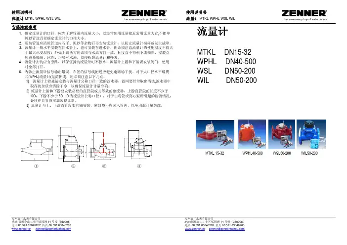
福州真兰水表有限公司 福州真兰水表有限公司安装注意事项1.确定流量计的口径,应先了解管道内流量大小,以经常使用流量接近常用流量为宜,不能单纯以管道直径确定流量计的口径大小。
2.新装管道应清除管道内石子、泥砂等杂物后再安装流量计,以防止流量计损坏或发生故障。
3.流量计一般水平安装在回水管上,也可安装在进水管,但必须注意流量计的使用温度不得大 于最大承受温度;外壳上箭头方向必须与水流方向一致,标度盘不得朝下或倾斜,安装点 应避免曝晒、冰冻、污染和水淹,以便拆装流量计和抄表。
4.流量计安装应有旁路,以保证拆装流量计时不停水,流量计上游和下游要安装阀门,使用 时全部打开。
5.为防止流量计信号输出错误,布置的信号线附近应避免电磁场干扰。
对于大口径水平螺翼 式(WPHL)流量计(见简图2),还必须注意以下几点:1) 流量计上游处请安装与流量计公称口径一致的滤水器,滤网要经常取出清洗,滤水器中 积存的杂质应清除干净,以确保流量计计量准确。
2) 流量计上游和下游要安装必要的直管段或其等效的整流器,上游直管段的长度不少于 10D ,下游不少于5D (D 为流量计公称口径),对于由弯管或离心泵所引起的湍流情况, 必须在直管段前加装整流器。
3) 流量计与上、下游直管段要同轴安装,密封垫不得突入管内,以免引起计量失准。
流量计MTKL DN15-32 WPHL DN40-500 WSL DN50-200 WIL DN50-200MTKL 15-32 WPHL40-500 WSL50-200 WIL50-200福州真兰水表有限公司 福州真兰水表有限公司用 途流量计是热量表或其它流量讯号采集系统的主要单元。
用于计量流经管道的流体的 总体积并发出讯号给后续系统。
既可直接在流量计指示装置上读出所通过的流体体积总量,也可在讯号采集的后续系统上读取。
流量计的选择根据管道公称口径和常用流量的使用情况,并参考技术参数来选择流量计的口径。
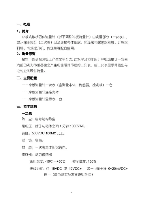
一、概述1、简介冲板式散状固体流量计(以下简称冲板流量计)由测量部分(一次表),显示输出部分(二次表)以及连接壳体组成。
它经常与螺旋给料机、叶轮给料机、斗式提升机、传送带等配合使用。
2、测量原则物料下落到检测板上产生水平分力,此水平分力作用于冲板流量计一次表内部的测力传感器使之产生电信号并传送给二次表,由二次表显示并输出与之对应的瞬时流量。
二、主要配置——冲板流量计一次表(含测量本体,传感器,检测板)一台——冲板流量计连接壳体——冲板流量计显示表一台三、技术规格一次表防尘:自身结构防尘耐电压:端子与箱体之间1分钟1000VAC。
绝缘:500VDC,100M 以上。
涂饰:银色。
材质:一次表主体用铝铸件。
传感器:测力传感器适用温度: -10℃—+50℃安全载荷: 150%接线说明: 红15VDC或12VDC+ 黑—;输出绿0~20mVDC+ 白—(颜色以实际发货说明为准)四、操作(一)、安装使用注意事项1、模拟输入与输出信号对电子噪声敏感,请将这些线远离交流电源,并尽量缩短屏蔽电缆的长度,如现场有干扰,请将屏蔽电缆的屏蔽线良好接地。
2、冲板流量计测量的数据受以下三个因素影响:冲击角、检测板水平安装角度和物料自由下落高度。
所以当技术人员协助安装调试后不要轻易改动以上因素。
(二)校准1、初次使用(1)整流壳体和流路对接之后,将冲板流量计安装在整流壳体的基座上,将密封橡胶的法兰和地脚螺栓紧固,进行简单的水平调节。
(2)打开整流壳体门,先将轴插入轴套内,将轴套内的紧固顶丝紧固。
(3)将冲击板通过瓦座穿在轴上,将冲击板调整到合适的角度后(对地角度:60-90度),将冲击板固定在轴上。
(4)将阻尼油注入阻尼器,使阻尼器中充满油且无气泡。
(5)传感器输出红、黑端电源10-15VDC ;绿、白端输入0~20mVDC 。
(6)接线图: (以实际发货为准)传感器供电传感器输出红黑-白-绿现场变送器(7)标定冲板流量计现场校正主要采用实物校正的形式。
目录仪表的键盘和前面板-------------------------------------2 仪表功能----------------------------------------------------4 仪表程序----------------------------------------------------4 仪表键盘和中控方式的转换----------------------------6 仪表的启动和停止----------------------------------------7 仪表重量和容积方式的转换----------------------------8 给定量的输入----------------------------------------------8 显示事件信息----------------------------------------------8 服务数据----------------------------------------------------9 标定功能----------------------------------------------------9 调零-----------------------------------------------------14 计数器1或2的复位-------------------------------------13 安装与调整-------------------------------------------------13 维护与保养-------------------------------------------------14 事件信息----------------------------------------------------16(一)仪表的键盘1各按键的作用如下:启动键和停止键。

TABLE OF CONTENTS Introduction (4)Specifications (6)Installation (7)Operational Start-Up (9)Troubleshooting (11)Flow Monitor Information (12)Repair Kit Information (13)Statement of Warranty (15)INTRODUCTIONFluid entering the meter passes through the inlet flow straightener which reduces its turbulent flow pattern and improves the fluid’s velocity profile. Fluid then passes through the turbine blades causing it to rotate at a speed proportional to the fluid velocity. As each blade passes through the magnetic field, created at the base of the pickoff transducer, AC voltage (pulse) is generated in the pick-up coil (see Figure 1). These impulses produce an output frequency proportional to the volumetric flow through the meter. The output frequency is used to represent flow rate and/or totalization of fluid passing through the turbine flow meter.FIGURE 1Schematic illustration of electric signalgenerated by rotor movementTURBINE METERThe FTB-1400 Series Turbine Flow Meter is designed to withstand the rigorous demands of the most remote flow measurement applications. The FTB-1400 Series Flow Meter maintains measurement accuracy and mechanical integrity in the corrosive and abrasive fluids commonly found in oil field waterflood project pipelines, in-situ mining operations, offshore facilities and plant locations. Simple to install and service, it can operate in any orientation (horizontal to vertical) as long as the“flow direction” arrow is aligned in the same direction as the actual line flow. For optimum performance, the flow meter should be installed with a minimum of 10 diameters upstream pipe length and 5 diameters downstream pipe length.FIGURE 2Typical cross-section of FTB-1411 throughFTB-1441 turbine flow meterSPECIFICATIONSMATERIALS of CONSTRUCTION: Body : 316 Stainless SteelRotor : CD4MCU Stainless SteelRotor Support and Bearings : 316 Stainless SteelRotor Shaft : Tungsten CarbideOPERATING LIMITATIONS:Temperature: -150 °F to +350 °F (-101 °C to +177 °C) The metershould not be subjected to temperatures above +350° F(177° C), or below -150° F (-101° C) or the freezingpoint of the metered liquid. High temperatures willdamage the magnetic pick-up, while lower temperatureswill limit the rotation of the rotor.Pressure : Maximum pressure ratings as follows:5,000 psi ─ all NPT meters up to 2"2,000 psi ─ 3" male NPT1,500 psi ─ 4" male NPT1,000 psi ─ 6" male NPT800 psi ─ all grooved end metersNote: Consult factory for pressure ratings for flanged meters. Accuracy:± 1.0% of reading Repeatability: ± 0.1%Calibration: Water (NIST Traceable Calibration) Corrosion: All FTB-1400 series turbine meters are constructed ofstainless steel and tungsten carbide. The operator mustensure that the operating fluid is compatible with thesematerials. Incompatible fluids can cause deterioration ofinternal components and cause a reduction in meteraccuracy.Pulsation andVibration: Severe pulsation and mechanical vibration will affectaccuracy and shorten the life of the meterFiltration: If small particles are present in the fluid, it is recommendedthat a strainer be installed upstream of the meter (see Table 1 WARNING: Pressure in excess of allowable rating may cause the housing to burst and cause serious personal injury.FLOW MONITOR:For a complete flow monitor package, Omega offers the FTB-1400 Series Flow Monitors (see Appendix B on page 12 for flow monitor information). These digital signal processing displays utilize the low-level frequency input from the FTB-1400 Series Turbine Meters to calculate flow rate and total. When ordered with an Omega FTB-1400 Series Turbine Meter, the included factory calibration will provide dependable and accurate flow information.REPAIR KIT:The FTB-1400 Series Turbine Meter Repair Kit is designed for easy field service of a damaged flow meter, rather than replacing the entire flow meter (see Appendix B on page 12 for repair kit information).Repair parts are constructed of stainless steel alloy and tungsten carbide and are factory calibrated to ensure accuracy throughout the entire flow range. Each kit is complete and includes the calibrated K-factor which is used to recalibrate the flow monitor or other electronics to provide accurate output data.INSTALLATION INSTRUCTIONSPrior to installation, the flow meter should be checked internally for foreign material and to ensure the turbine rotor spins freely. Fluid lines should also be checked and cleared of all debris.The flow meter must be installed with the flow arrow, etched on the exterior of the meter body, pointing in the direction of fluid flow. Though the meter is designed to function in any position it is recommended, where possible, to install horizontally with the magnetic pick-up facing upward.The liquid being measured should be free of any large particles that may obstruct rotation of the rotor. If particles are present, a mesh strainer should be installed upstream before operation of the flow meter. (See Table 1 on page 8.)TABLE 1 Strainer Mesh Installation DetailsThe preferred plumbing setup is one containing a by-pass line (Figure 3 on page 10) that allows meter inspection and repair without interrupting flow. If a by-pass line is not utilized, it is important that all control valves be located downstream of the flow meter (Figure 4 on page 10).This is true with any restriction in the flow line that may cause the liquid to flash. If necessary, air eliminators should be installed to ensure that the meter is not incorrectly measuring entrained air or gas.PARTNUMBER STRAINER MESH CLEARANCE FILTER SIZE FTB-1411, FTB-142160 × 60 .0092 260 Micron FTB-1412, FTB-142260 × 60 .0092 260 Micron FTB-1413, FTB-142360 × 60 .0092 260 Micron FTB-142460 × 60 .0092 260 Micron FTB-1425 60 × 60 .0092 260 MicronFTB-1431 20 × 20 .0340 .86mm FTB-1441 20 × 20 .0340 .86mmCAUTION: Damage can be caused by striking an empty meter with a high velocity flow stream.It is recommended that a minimum length, equal to ten (10) pipe diameters of straight pipe, be installed on the upstream side and five (5) diameters on the downstream side of the flow meter. Otherwise, meter accuracy may be affected. Piping should be the same size as the meter bore or threaded port size.Do not locate the flow meter or connection cable close to electric motors, transformers, sparking devices, high voltage lines, or place connecting cable in conduit with wires furnishing power for such devices. These devices can induce false signals in the flow meter coil or cable, causing the meter to read inaccurately.If problems arise with the flow meter and monitor, consult Appendix A (Troubleshooting Guide) on page 11. If further problems arise, consult the factory.If the internal components of the turbine flow meter are damaged beyond repair, turbine meter repair kits are available. Information pertaining to the turbine meter repair kits is referenced in Appendix B on page 12.OPERATIONAL START-UPThe following steps should be followed when installing and starting the meter.WARNING: Make sure that fluid flow has been shut off and pressure in the line released before attempting to install the meter in an existing system.1. After meter installation, close the isolation valves and open theby-pass valve. Flow liquid through the by-pass valve for sufficient time to eliminate any air or gas in the flow line.CAUTION: High velocity air or gas may damage the internal components of the meter.2. Open upstream isolating valve slowly to eliminate hydraulic shockwhile charging the meter with the liquid. Open the valve to full3. Open downstream isolating valve to permit meter to operate.4. Close the by-pass valve to a full closed position.5. Adjust the downstream valve to provide the required flow ratethrough the meter. Note: The downstream valve may be used as a control valve.FIGURE 3Meter installation utilizing a by-pass line(Shown with an FTB-1400 Series Flow Monitor)FIGURE 4Meter installation without utilizing a by-pass lineAPPENDIX ATROUBLESHOOTING GUIDE Trouble Possible Cause RemedyMeter indicates higher than actual flow rate -Cavitation-Debris on rotor support-Build up of foreign materialon meter bore-Gas in liquid-Increase back pressure-Clean meter-Clean meter-Install gas eliminatorahead of meterMeter indicates lower than actual flow rate -Debris on rotor-Worn bearing-Viscosity higher than calibrated-Clean meter and add filter-Clean meter and add filter-Recalibrate monitorErratic system indication, meter alone works well (remote monitor application only) Ground loop in shielding Ground shield one placeonly. Look for internalelectronic instrumentground. Reroute cablesaway from electrical noiseIndicator shows flow when shut off Mechanical vibration causesrotor to oscillate without turningIsolate meterNo flow indication. Full or partial open position Fluid shock, full flow into drymeter or impact caused bearingseparation or broken rotor shaftRebuild meter with repairkit and recalibrate monitor.Move to location wheremeter is full on start-up oradd downstream flowcontrol valveErratic indication at low flow, good indication at high flow Rotor has foreign materialwrapped around itClean meter and add filterNo flow indication Faulty pick-up Replace pick-upSystem works perfect, except indicates lower flow over entire range By-pass flow, leak Repair or replace by-passvalves, or faulty solenoidvalvesMeter indicating highflow, upstream pipingat meter smaller thanmeter boreFluid jet impingement on rotor Change pipingOpposite effects of above Viscosity lower than calibrated Change temperature,change fluid or recalibratemeter11APPENDIX BFTB-1400 SERIES FLOW MONITOR Simplified Version• Displays rate and/or total• Large 8 digit by 3/4” display• Front panel programming• NEMA 4X enclosure• Five selectable units of measure• Programs in seven simple stepsPart Number InformationFTB 1400 X DMounting StyleM = Meter MountR =Remote MountS =Swivel Mount Advanced Version• Displays rate and/or total• Large 8 digit by 3/4” display• Front panel programming• NEMA 4X enclosure• Thirteen selectable units of measure• Selection of time intervals for rate measurement• Ten point linearization• Provides additional programming optionsPart Number InformationFTB 1400 X D AMounting StyleM = Meter MountR =Remote MountS =Swivel Mount1213FTB-1400 REPAIR KITFigure 5Typical turbine meter component directoryFlow Meter SizeRepair Kit FitsMeter Part NumberRepair KitPart Number3/8" FTB-1411,FTB-1421 FTB-1400A-RK 1/2" FTB-1412, FTB-1422 FTB-1400B-RK 3/4" FTB-1413, FTB-1423 FTB-1400C-RK 7/8" FTB-1424 FTB-1400D-RK 1" FTB-1425 FTB-1400E-RK 1-1/2" FTB-1431 FTB-1400F-RK 2" LowFTB-1441 FTB-1400F-RK Standard Magnetic Pick-upAll Meter SizesFTB-1400-MPNOTES 141516。
流量计计量差异说明
上游涡轮流量计(中实华流量计)
型号:TBQZ—80C
工作/公称压力: 1.0—1.6MPa
流量范围:20—400方
准确度: 1.5级
编号:X6075176
生产厂家:浙江天信仪表
下游涡轮流量计(昌乐金天马燃气公司流量计):
型号:TBQZ—100C
工作/公称压力: 1.0—1.6MPa
流量范围:32—650方
准确度: 1.5级
编号:10105144
生产厂家:浙江天信仪表
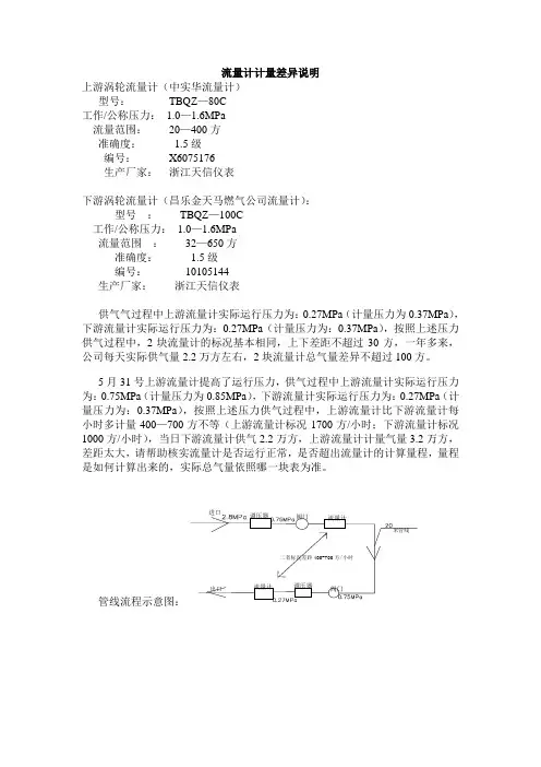
供气气过程中上游流量计实际运行压力为:0.27MPa(计量压力为0.37MPa),下游流量计实际运行压力为:0.27MPa(计量压力为:0.37MPa),按照上述压力供气过程中,2块流量计的标况基本相同,上下差距不超过30方,一年多来,公司每天实际供气量2.2万方左右,2块流量计总气量差异不超过100方。
5月31号上游流量计提高了运行压力,供气过程中上游流量计实际运行压力为:0.75MPa(计量压力为0.85MPa),下游流量计实际运行压力为:0.27MPa(计量压力为:0.37MPa),按照上述压力供气过程中,上游流量计比下游流量计每小时多计量400—700方不等(上游流量计标况1700方/小时;下游流量计标况1000方/小时),当日下游流量计供气2.2万方,上游流量计计量气量3.2万方,差距太大,请帮助核实流量计是否运行正常,是否超出流量计的计算量程,量程是如何计算出来的,实际总气量依照哪一块表为准。
管线流程示意图:
调压器阀门流量计
调压器
流量计阀门
进口
出口
米管线
二者标况差距400-700方/小时。

流量计性能测定实验装置说明书天津大学化工学院化工基础实验中心2006年7月目录一、实验装置的功能及特点二、主要仪器仪表及技术参数三、实验装置流程四、实验方法及步骤五、操作时应注意的事项六、附录一、实验装置的功能及特点本实验装置具有如下功能:⑴ 了解各种流量计(节流式、转子、涡轮)的结构、使用方法和性能。
⑵ 了解流量计的标定方法。
⑶ 测定文丘里流量计的流量标定曲线(流量-压差关系)和流量系数和雷诺数之间的关系(Re 0 C 关系)。
实验设备的特点:⑴ 结构紧凑, 流程简单, 设备投资少。
⑵ 使用方便, 安全可靠, 节省实验时间。
⑶ 装置体积小, 重量轻, 移动方便。
二、主要仪器仪表及技术参数⑴ 离心泵: 型号 WB 70/055 转速n 2800 转/分 流量Q 20~120 L /min, 扬程H 19~13.5m⑵ 贮水槽: 550mm ×400mm ×450mm ⑶ 试验管路: 内径 26.0mm⑷ 涡轮流量计:φ25,最大流量 10m 3/h ,仪表常数830.54次/升 ⑸ 文丘里流量计:喉径φ15mm⑹ 转子流量计:LZB-25,量程0.25-2.5m 3/h ⑺ 铜电阻温度计;⑻ 差压变送器: 0-200kPa三、实验装置流程用离心泵3将贮水槽1的水直接送到实验管路中,经涡轮流量计计量后分别进入到转子流量计、文丘里流量计,最后返回贮水槽1。
用文丘里流量计测量时把阀门5打开,阀门6关闭;转子流量计测量时把阀门6打开,阀门5关闭。
流量由调节阀5、6来调节,温度由铜电阻温度计测量。
实验流程示意图见图1图1 流量计实验流程示意图1-水箱;2-放水阀;3-离心泵;4-排水阀;5-文丘里流量计调节阀;6-转子流量计调节阀;7-转子流量计;8-文丘里流量计;9-平衡阀;10-压力传感器;11-涡流流量计四、实验方法及步骤⒈关闭泵流量调节阀5、6,启动离心泵。
⒉测取文丘里流量计的性能,按流量从小到大的顺序进行实验。
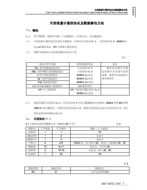
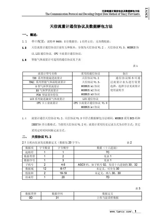
天信流量计通信协议及数据解包方法一、概述:1.1串口配置:波特率9600,8位数据位,1位停止位,无奇偶校验。
1.2天信流量计通信协议目前有五种版本,分别为天信协议V1.2 ,天信协议V1.3,MODBUS 协议,LUX 通信协议, CPU 卡流量计通信协议。
1.3 智能气体流量计可选用的通信协议见下表表11.4流量计通信天信协议V1.2、天信协议V1.3中浮点数据解包方法相同,MODBUS 采用BCD 码和IEEE754浮点数格式。
当使用天信协议V1.2时,流量计采用历史记录方式为启停方式;其它采用定时时间间隔记录方式。
二、 天信协议V1.22.1主机向仪表发送数据定义(数据包20字节): 表2 数据项 字节数量字节顺序数据(十六进制)起始符 1 1 7C 数据类型 1 2 见表1 数据序号 1 3 见表1子机号 2 4-5 ASCII 码,如子机号02,发送十六进制的30、32数据域 12 6-17 未定义,可全为30 校验和 2 18-19 未定义,填入30、30结束符1207D表3数据类型 数据序列 数据定义 0D 31上传当前采样数据流量计型号名称 采用的通信协议 备注TDS 系列智能旋进流量计 TBQZ 系列智能气体涡轮流量计G 型气体罗茨流量计 B3气体罗茨流量计 FCM 型流量补偿仪 天信协议V1.2 天信协议V1.3, MODBUS/A1协议 MODBUS/A2协议 MODBUS/A3协议 通信协议版本可通过流量计表头进行设置选择,选择方法见流量计使用说明书LUX 系列旋进漩涡气体流量计LUX 通信协议CPU 卡工业流量计CPU 卡流量计通信协议 V1.0MODBUS/A4协议2.2仪表向主机回送数据定义:表4数据项字节数量字节顺序数据(十六进制)起始符 1 1 7C子机号 2 2-3 ASCII码,如子机号02,发送十六进制的30、32 数据序列 1 4 见表1数据域见表2 见表2 见表2校验和 2 未启用,填入30、30结束符 1 7D表5 上传数据定义字节数量字节顺序数据(十六进制)备注5-12 当前流量浮点数格式13-24 总量14-17为BCD码18-25为浮点数格式25-32 温度浮点数格式33-40 压力浮点数格式41-48 工况瞬时流量浮点数格式当前数据4649-50 FLAG标志(未定义)2.3 举例:设仪表表头的通信地址(默认子机号)为02当前显示为:总量8700标况30.93 工况30.97温度20.0 压力101.19上传当前参数主机发送的数据:7C 0D 31 30 32 30 30 30 30 30 30 30 30 30 30 30 30 30 30 7D主机接受的数据:7C 30 32 31 30 35 37 3B 3B 3D 30 30 30 30 30 30 30 3E 34 33 3F 38 30 31 30 35 3530 30 30 30 30 30 37 36 35 32 3F 38 30 30 35 37 3B 3E 39 38 30 30 30 30 30 7D其中:7C ;起始位30 32 ;仪表子机号31 ;数据序列30 35 37 3B 3B 3D 30 30 ;瞬时流量,浮点数为057BBD00,解包后十进制数为30.935浮点数解包方法见下面所述。

智能流量频率变送仪表使用说明书一、概述●适用范围本系列智能数字显示流量频率仪表是智能型、高精度的数显流量频率控制测量仪表,与涡街、涡轮、电磁流量计频率传感器及变送器配接可构成各种量程和规格的流量频率测控系统。
(可以测量电压、电流、转速、频率等各种参数,可与PLC变频器配接构成各种测量系统。
可以带峰值,谷值。
订货请来电说明。
)二、主要技术指标基本误差:0.2%FS,14位A/D转换器(最大18位A/D转换器,订货时注明)。
输入信号:·NPN、PNP、开关量·电流: 0~10mA、4~20mA等(输入阻抗≤250Ω)·电压: 0~5V、1V~5V、mV等(输入阻抗≥1MΩ)采样周期:0.2S(10~200次/秒,用户可选)显示:双排4位LED数码管显示。
报警输出:仪表可带多个继电器输出,继电器触点容量 AC220V/5A或AC220V/1A。
最多可带16个继电器,可选择上限、下限控制,控制设定值和回差值全量程内自由设定变送输出:4~20mA、0~10/20mA(负载电阻≤250Ω,负载过大需注明)1~5V、0~5V、0~10V(负载电阻≥200KΩ)。
采用12位数字D/A芯片,隔离输出。
通讯输出:隔离通讯接口RS485/RS232 波特率1200~9600bps馈电输出:DC24V/30mA、DC12V/30mA温度补偿:0~50冷端温度自动补偿,误差:±1℃电源:开关电源 85~265VAC或DC24V或DC12V功耗:4W环境温度:(-20~70)℃(常温下开机运行30分钟后,可逐渐承受极限温度)(0~50)℃ (热电偶信号输入)相对湿度:≤85% 无凝露避免在带有腐蚀性和易燃易爆气体中使用面板尺寸: 160mm×80mm、96mm×96mm、96mm×48mm、72mm×72mm、48mm×48mm(本公司仪表自行研发生产,种类多,功能全,如用户可选快速采样,最快可以500次/秒,高精度18位A/D 采集,高精度16位D/A输出,输入信号20段曲线修正,满5位显示或6位显示,液晶显示,特殊的输入信号,多个继电器报警蜂鸣器输出,大功率的馈电输出等,订货时注明)三、端子接线⑴C规格96×48×100尺寸的仪表四、操作说明(一)按键功能■—在设定状态时,用于切换显示参数提示符和相应的设定值。
天信流量计V1.3协议例程编写人:李超群编写日期:2011年12月5日一、例程功能介绍1、本例程可以将天信V1.3协议的流量计中的数据(瞬时流量,累计流量,温度,压力)读出,经处理后以合适的格式存放在RTU的寄存器中。
本例程可以读取四块流量计的数据,流量计地址是01,02,03,04.2、数据存贮地址寄存器地址对应流量计地址数据数据保存类型41001-41002流量计地址为01 瞬时流量REAL41003-41006 总流量DUINT 41007-41008 温度REAL 41009-41010 压力REAL41011-41012流量计地址为02 瞬时流量REAL41013-41016 总流量DUINT 41017-41018 温度REAL 41019-41020 压力REAL41021-41022流量计地址为03 瞬时流量REAL41023-41026 总流量DUINT 41027-41028 温度REAL 41029-41030 压力REAL41031-41032流量计地址为04 瞬时流量REAL41033-41036 总流量DUINT 41037-41038 温度REAL 41039-41040 压力REAL3、将多个天信流量计的两根RS485通讯线并起来接到RTU的COM1的485上。
4、RTU通讯参数的设置由于与天信流量计通讯的是COM1端口,所以要将COM1设置成如下所示:二、编程及测试环境硬件环境:Super-E50软件环境:WINDOWS XP 、OPENPCS2008、ESet2009.由于该例程是在super-E50上编译的,OPENPCS程序选择配置工具选的是E50,所以在其它控制器上未必可以直接拿来用,所以要做相应处理:打开openpcs程序选择配置工具文件夹,打开openpcs.exe选择与自己控制器对应的底层程序,然后在打开本例程重新编译一下再下载到RTU中即可使用。
目录仪表的键盘和前面板-------------------------------------2 仪表功能----------------------------------------------------4 仪表程序----------------------------------------------------4 仪表键盘和中控方式的转换----------------------------6 仪表的启动和停止----------------------------------------7 仪表重量和容积方式的转换----------------------------8 给定量的输入----------------------------------------------8 显示事件信息----------------------------------------------8 服务数据----------------------------------------------------9 标定功能----------------------------------------------------9 调零-----------------------------------------------------14 计数器1或2的复位-------------------------------------13 安装与调整-------------------------------------------------13 维护与保养-------------------------------------------------14 事件信息----------------------------------------------------16(一)仪表的键盘1各按键的作用如下:启动键和停止键。
欢迎阅读目录一、概述 (1)二、功能特点 (1)三、主要技术指标 (1)四、工作原理 (2)小信号切除功能,切除范围0-5%可选累积流量值可通过面板按键清零,清零操作可锁掉电保护功能,累积流量值掉电保持时间大于5年,所有设定值掉电后永久保持先进的模块化结构,配合功能强大的仪表芯片,功能组合、系统升级非常方便三、主要技术指标输入信号(1)模拟量输入:热电阻:Pt100热电偶:K、T、E电压:0~5V、1~5V电流:4~20mA、0~20mA或0~10mA (2)脉冲量输入:波形:矩形、正弦或三角波电源:开关电源85~265VAC功耗4W以下使用环境:环境温度:0~50℃相对湿度:<85%RH四、工作原理本仪表原理如框图所示,本积算仪以单片微处理器为核心,通过输入信号电路把各种模拟信号经A/D 转换器转换成数字信号,或频率信号直接由微处理器进行计数采用,微处理器根据这些采样结果和数字设定内容进行计算并显示和输出。
2五、操作说明 (一)仪表面板如图所示,左侧三个指示灯依次为: ① 瞬时流量指示灯 ② 压力指示灯 ③ 温度指示灯 右侧二个指示灯为 ① 上限报警灯 ② 下限报警灯 显示窗显示内容:上排四位数码管显示瞬时流量值 下排八位数码管显示累积流量值 (二)操作键说明SET -参数设定键,按下此键盘,可按次序输入参数,修改完毕一个参数请按SET 键存贮并进入下一个参数值的修改。
▲—在设定状态时,用于增加设定值。
▼—在设定状态时,用于减少设定值。
若按下▲或▼不动,数值将快速增减,松手后停止。
模 拟量通 道开 A/D单片机面板设定 光电 通讯CLR-清零键,按下此键,上排出现-CL-,下排显示1230,用▲和▼键把1230设成1234后,再按SET键,则完成累积量清零,输入其它值无效。
SEL-选择键,工作状态下,选择显示瞬时流量、压力或温度,或分时巡回显示流量、压力和温度值,同时相应的指示灯亮。
在设定参数时,选择键用作选择小数点的位数,范围从0~3。