AD838操作员培训手册2
- 格式:ppt
- 大小:2.57 MB
- 文档页数:13
主题:AD员的软件操作手册文档性质:操作手册创建时间:2011年9月15日编写人:郑传菊审批人:陈栽林目录一、业务操作导航 (3)二、各业务功能操作说明 (4)销售管理 (4)1.1 订货管理 (5)1.1.1 订货单导出 (5)1.1.2加盟商订货 (5)1.1.3加盟商订货取消 (7)1.1.4加盟商订货调整 (8)1.1.5订货发货(按款) (9)1.1.6 订货综合查询 (10)1.2 销售单据 (11)1.2.1 批发销售单 (11)1.2.2 直营调拨单 (15)1.3 补货管理 (19)1.3.1 补货申请单 (19)1.3.2补单缺口 (21)1.4退货管理 (21)1.4.1 退货申请单 (21)1.4.2 批发退货单和直营退货单 (22)营销系统分析 (23)2.1专卖店零售单据录入 (23)2.2 专卖店零售单据查询 (24)2.3 加盟店盘点表和直营店盘点表 (24)2.4全国库存分布统计 (25)2.5发货及零售综合查询 (26)2.6 加盟店进销存统计 (27)三、基本数据查询案例 (29)例1 查询某款的剩余库存明细, (29)例2 查询某个客户或多个客户近期的发货和退货明细。
(30)例3 专卖点的业绩的查询 (31)例4 对于未使用门店系统的加盟店或者专卖店的盘点数据查询。
(31)四、常见问题集锦及处理方法 (33)一、业务操作导航二、各业务功能操作说明销售管理在销售中,无非是四种情况即订,销,补和退。
1.1 订货管理在订货管理模块中,AD员所使用的主要是:订单管理,订货综合查询和订货发货(按款)。
1.1.1 订货单导出模块功能解释:导出商品资料和导入订货会的订货单界面:细点功能介绍:组合条件查询:选择查询的条件导出EXCEL:将组合条件查询过来的商品资料出到EXCEL导入EXCEL:将订货会过来的订货EXCEL数据(EXCEL格式需要指定)导入到系统中生成订货单:将导进的来数据转货成订货单1.1.2加盟商订货模块功能解释:主要用于订货会上加盟商订货输入、统计及分类,以便据此下加工单或生产计划单。
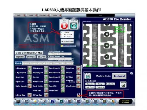
文件名称:ASMAD838粘片机操作规程文件名称:ASM AD838 粘片机操作规程1.目的规范AD838粘片机的操作与管理,以确保产品的质量。
2.范围适用于本公司粘片工序AD838粘片机的操作。
3.外围设施3.1 电压100~240V AC3.2 频率50/60HZ3.3 压缩空气最少4bar4.操作环境4.1 环境空气温度5-40℃4.2 相对湿度典型70%@ 32℃5.开机操作过程5.1.1 开机前依次打开外围设施的开关.压缩空气开关.电源开关。
5.1.2 检查紧急按钮EMO(EMERGENCY STOP)保持在松开状态。
5.1.3 找出机器前端靠近键盘的电源开关ON/OFF 按钮,按绿色(ON)键启动机器。
当显示器进入视窗页面之后,双击Shortcut to AD830.exe 图表启动系统软件,提示窗口“ASMHMI”将会显示。
并且会显示启动进程,等待直到完成。
6.操作编程6.1器件更换6.1.1吸嘴进行清洁.检查或更换时,可以从Bond→Material 进入并按Change Collet 按钮更换吸嘴。
当吸嘴安装完后,按提示窗口的“Close”按钮完成。
6.1.2 顶针进行清洁.检查或更换时。
可以从Bond→Material 进入并按 Change EJ Needle 按钮,系统信息将会提示要求折除顶针帽,顺时针方向旋转使顶针帽松开进行操作顶针。
当安装顶针完成后,按提示窗口的“Close”按钮,系统提示要求确认顶针帽安装按“YES”按钮完成。
6.1.3 导电胶更换时,可以从Bond→Material进入并按 Change Epoxy 按钮更换。
当导电胶安装完后,按提示窗口的“Close”按钮完成。
6.1.4 圆片更换时,可以从Bond→Material 进入并按Change Wafer的向上箭头按钮取出圆片。
更换圆片后,按向下箭头按钮完成装载圆片。
6.1.5 料盒更换时,按操作页面下方的F9 第3个Change Magazine 进行转换料盒。

ASM DA Technical DiscussionFeasibility Studies on Dual-Dispense Upgrade &New ASM Die Bonder Presentations11-June-2009Feasibility Studies ofDual-dispensing upgrade on 898/8912 Dimensional checkHardware & Software changes involvedSummaryASM New 8”Die Bonder AD838ASM New 12”Die Bonder AD8912SD-AFeasibility Studies on Dual-Dispensing UpgradeDispensing Modules Space OccupiedSpace notenough420mm220mm AD8912Space not enough420mm220mm AD898Stack loader outside machine530mm530mm AD830RemarksRef. photoDispense space with stack loader dismantledDispense space with stack loaderinstalledModelHiPEC modulebd assignmentbd assignmentLimitations for 898/8912 to upgrade with dual-dispense module Insufficient spaceFor dispensing moduleFor additional HiPECFor additional servo boardsFor additional I/O boardsDifficulties for 898/8912 to upgrade with dual-dispense module Complete new machine support structuresComplete new workholderComplete new s/wUnproven engineering and field experienceAD838 Automatic High Speed Epoxy Die BonderSystem overviewApplicationsFeatures highlights High bonding speedExcellent accuracyOutstanding flexibility CapabilitiesSpecifications2001200320042005200620072008AlMg BHAVM5 Vision HIPEC controlEagle vision Linear motorUltra light BHLinear BHLinear ejectorDual core CPUUPHUPH = 10,000UPH = 17,200 UPH: 14,000High throughputUPH: 17,200Fastest cycle time 200ms with PR alignmentPrecise placementXY placement: ±1 mil (±25 µm)Die rotation: ±1°Design for reliabilityProlonging MTBF and MTBRExcellent flexibilityFast conversion: 30 minsWide range of application*High bonding speedCycle time: 200* msUPH: 17,200*+Excellent placement accuracyXY direction: ±1 mil (±25.4 µm) @ 3σTheta rotation: ±1°@ 3σCost saving with linear motorimplementationFast and easy packages conversion withprogrammable track controlImplementing flexibility with wide rangeof materials handlingAD838Automatic High SpeedEpoxy Die BonderSOT23SC-70SOICQFPQFNSSOPAnd more…SOT223W i de R an g eo fA p pl i c a ti o nWafer system Workholder systemDual dispensing systemBonding systemInput stack loading systemAutomatic output magazine systemInspection systemSupporting dual dispensing system Linear motor driven wafer table systemPatented double decouplingbond head systemAdvanced PRinspection system UPH: 17,200+Implementing patented designDouble decoupled linear bond head system Stable and rigid module designHigh speed bondingExcellent acceleration performanceX direction: up to 2.2G Y direction: up to 15G Z direction: up to 15GAutomatic missing die detectionSoft landing capabilityAuto learn pick and bond levelingVoice coil control for accurate programmable pick / bond force controlAir flow missing die detection Technical specifications:Bond force: 30 -300 gf*Supporting rotary collet bond arm system (option)Double decoupled linear bond head designSupporting rotary collet bond arm system (option)High speed bond arm designUS PATENTEDUS PATENTEDSaving cost by widely implementing linear motor in Workholder indexing systemWafer table systemBondhead systemBond alignment optic systemEjector systemAdvantagesHighly durableMinimizing maintenance costHighly reducing lubrication costLess wear out componentsChecking dispensing performance before die bonding Epoxy placementSize and shapeSimple selections for setup on various inspectionsCheck for minimum / max coverageLinear motor drivenwafer table systemBondhead accuracy with fine resolutionX direction: 0.008 mil (0.2 µm)Y direction: 0.02 mil (0.5 µm)Advanced PR inspection systemPrecise PlacementXY direction: ±1 mil @ 3σDie rotation: ±1°@ 3σPrecise PlacementXY direction: ±1 mil @ 3σDie rotation: ±1°@ 3σWorkholder system withfine indexing resolutionLinear motor ejectorResolution: 0.5 µm / countAutomatic input stack loading systemLocating inside the machine for compact size in factoryAutomatic output magazine systemAutomatic input magazine system (option)Stack loading systemAutomatic output magazine systemAutomatic input magazine system (option)Simple and easy conversion of anvil blocksDispense Anvil BlockBond Anvil BlockSlot for sliding the lock of anvil blockSupporting Window®XP operation system and graphical user interfaceWidely implementing common control platform MouseKeyboardJoystickKeyboard Mouse and joystick Graphical user friendly interfaceSupporting multiple language user menu for your selectionEnglishSimplified ChineseTraditional ChineseEnglish Traditional ChineseSimplified ChineseCapabilityBonding before whole substrate being dispensed Preventing epoxy from being dryMean time between dispense / bondLeftdispenser position Rightdispenser positionBond position(2)Leftdispenser positionRightdispenser positionBond position3 work stations on same substrate2 work stations on same substrate (1): 2 dispensing on same substrate(2): 1 dispensing + 1 bonding on same substrate(3)Each work station with individual substrate(1)Left dispenser position Rightdispenser positionBondpositionTime 1Time 2Pre-eject Process: Ejector moves from ejector cap surface to die back surface Sync Pick Level:Ejector moves uplevel beforesynchronize motionSynchronize motionEjector and BHZ movewith synchronize motion**Recommended synchronize speed: 5~10µm/msExcellent performance of epoxy coverage and bond line thicknessPerformance informationPackage: SOP 8LDie size: 85 x 153 mil (2,159 x 3,886 µm)0.39-0.240.310.180.670.490.630.82Range 0.150.700.04Max.= 1Die Tilt (mil)0.150.490.00±1°@ 3σDie Rotation (deg.)0.59 –1.38±1 @ 3σ±1 @ 3σPassing Spec.0.050.180.19S.D.0.77Max.0.59-0.51Min.Epoxy Thickness(mil) Y Placement(mil)X Placement(mil)Simple bonding processONLY pick and place of die Heater bonding at bond side No epoxy dispensing / stampingExcellent bond line thickness control Depending on screen printing thicknessWith fewer fillet than traditional epoxyPre-printed B-stage epoxyDie top~25µmDie size: 115 x 113 milDie size: 20 mil x 20 milDie size: 20 mil x 16 milSupporting automatic wafer handling loading capability (option)In-line capability with multi-dice handling (option)Wafer mapping handling capabilityAD838 cascadeAutomatic waferloading systemIn-lining with snap curing oven Wafer mapping handlingHigh bonding speedCycle time: 200* msUPH: 17,200*+Excellent placement accuracyXY direction: ±1 mil (±25.4 µm) @ 3σTheta rotation: ±1°@ 3σHigh flexibility6”& 8”waferShort conversion time –< 20 minutesFast dry epoxy handlingQuality assuranceStandard pre/post bond inspectionFully automatic operation with wafer handlerAD838Automatic HighSpeed Epoxy DieBonder* Remark: all actual performance is package and application dependentDimensions & WeightBond Head SystemFacilities RequiredPattern Recognition SystemWafer SystemSystem PerformanceBond force30 -300 g (programmable)Voltage 110 / 200 / 220 / 240 VAC Frequency50/60 Hz (pre-set at factory)Compressed air Min. 71 PSI (5 bar)Power consumption~1,800 W (with heater)~1,500 W (without heater)Track widthStandard 0.47”–2.95”(11.94 –74.93 mm)Option2.95”–4”(74.93 –101.6 mm)PR system 256 grey levels Resolution 512 pixels x 512 pixels Position accuracy ±¼pixel Angular accuracy ±0.1°Die size 6 ×6 -400 ×400 mil(0.15 ×0.15 –10.16 ×10.16 mm)Substrate sizeLength4.33”–10.24”(109.98 –260.00 mm)Width 0.47”–2.95”(11.94 –74.93 mm) (standard)2.95”–4.00”(74.93 –101.60 mm) (option)Thickness4 -39 mil (0.10 –1 mm)Magazine sizeLength 4.33”–10.63”(109.98 –270 mm)Width 0.63”–4.20”(16 –106.68 mm)Height2.68”–3.54”(68 –89.91 mm)Wafer size8”(203.2 mm) wafer (standard)6”(152.4 mm) wafer (option)Auto-theta alignment ±10°rangeCycle time 200 ms*XY placement ±1mil (±25.40 µm)@ 3σDie rotation±1°@ 3σWorkholder SystemMaterials Handling CapabilityDimensionWidth x Depth x Heightw/o input mag. 55”x 49”x 82”(1,390 x 1,240 x 2,080 mm)w/ input mag.71”x 49”x 82”(1,800 x 1,240 x 2,080 mm)Net weight ~ 2,970 lb (1,350 kg)ASM New 12”Automatic Die BonderAD8912SD-AAll-around stacking processExcellent flexibility to handle all around packages PBGA, TBGA, FBGA, SOT, SOIC, QFN, TQFP, TSOP etcImplementing latest designPatent pending design: two –stage ejecting systemProgrammable bond force controlProviding up to 5,000g bond forcePyramidApproachStairApproachFOWApproachTop die Middle dieBottom dieCrossingApproachArrow ApproachAnd more……High speed bondingLarge range of bond force to fit your needUp to 5,000g bond forceSupporting micro-X bondingBond head X travel: up to 10mmSynchronized pick motionMaintaining constant pick force Preventing die crackingExcellent linear bond force response & controlExcellentPlacement AccuracyExcellent Placement Accuracy *Remark: all actual performance is package and application dependentStandard 2 in 1 dispensing capabilityEpoxy writer and dot dispensing Matrix substrate handling capability2”x 3”dispensing areaReal time epoxy position alignmentSupporting pattern dispensing18 standard patternsCustomized patternsStandard to: time-pressure pumpFlexible to equip with various dispensing algorithms (option)Screw pumpVolumetric valveTime-pressure pump with Musashi systemAnd more……Supporting pre-defined common dispensing patternsScrew pumpTime-pressure pumpVolumetric valveRobotic wafer handling system for maximum 12”wafer XY table travel: 13”X 13”Fast conversion for different wafer size8”to 12”and vice versaWaffle pack handling (option)Up to 12”wafer handling capability2”x 2”waffle pack (option)Thin die handling capabilityDie thickness: < 50µm dieFlexible to handle large range of die sizeProgrammable pre-peeling heightLess critical ejector pins arrangementFast picking motion with movable pre-peeling stage Supporting heating ejecting system (option) Up to 120°C2-stage ejecting systemCapable of handling ultra-thin substrate with front & rear track design High speed clamping systemIncreasing rigidity when using pivot springHigh flexibility for large range of substrateFlexible track width and downset substrate handlingTrack width: 15mm ~ 100mmDownset: up to 2.3mmFixed heater assembly on process platformSaving the conversion cost and timeProgrammable track widthand up/down motionImplementing universal anvil block concept Suitable for large range of substrate15mm ~ 80mmEquipping with heater block forLaminated stack dice bondingFOW / COW bondingAnd more……Temperature: up to 300°CPre-heat Main heaterPost-heatPackage dependentanvil plate Heat spreadHeater plate Support legs& insulationPrecision placement with various inspection stationDispensing area: substrate inspectionBonding area: pre-bond / post-bond inspectionOptional pre-bond automatic motorized zoom opticsWafer table: die inspectionExcellent image quality with monochromic illumination system Supporting ring and coaxial light depend on different inspection algorithmsPrecise PR image256 grey scale levels inspectionPosition accuracy : ±¼pixelAngle accuracy : ±0.1°Dispensing optics Bonding opticsWafer opticsPre-Bond InspectionLeadframe orientation check Leadframe contamination check Pad size, bent lead and missing lead Epoxy position Epoxy area Epoxy tailEpoxy on leadPost-Bond InspectionDie placement Die rotation Missing die Die inspectionEpoxy coverageX die placement (mils)Y die placementDie rotation (deg.)Online bonding performance trackingInput stack loading systemApplicable to various sizes of leadframesSupporting interleaf paper separatorAutomatic output magazine systemAutomatic input magazine system (option)Input magazine systemStack loading system Output magazine systemDimensions & WeightBondheadFacilities RequiredPattern Recognition SystemWafer StageSystem CapabilityBond force150 -5000 gVoltage 110/220 VAC (pre-set at factory)Frequency50/60 Hz (pre-set at factory)Compressed air 71 PSI (5 bar) minimumPower consumptionApprox. 1800 W (with heater)Approx. 1500 W (without heater)XY travel 2”x 3”(50.8 x 76.2 mm)Resolution XY 0.05 mil (1.25 µm)Z0.15 mil (3.81 µm)PR System 256 grey levelsResolution512 pixels x 512 pixels Position accuracy ±¼pixel Angle accuracy±0.1°Die size10 ×10 mil -1000 ×1000 mil(0.25 ×0.25 mm -25.4 ×25.4 mm)Package handled Leadframe, BGA Leadframe size Length 6.0”–11”(150 –280mm)Width 0.6”-3.15”(15 -80 mm)3”(76.2mm) Y-axis bond areaThickness 4 -30 mil (0.1 –0.75 mm) (standard)30 –79mil (0.75 -2mm) (option)Magazine size Length 6.0”–11”(150 -280 mm)Width 0.6”-3.35”(15 -85 mm)Height2.7”-6.0”(70 -153 mm)Wafer size Max. 12”(300 mm)XY table travel 13”×13”(330 ×330 mm) Conversion 5 mins (Device only)Ejector height0”-0.2”(0 -5 mm) linear programmableCycle time 320ms For ≥40 mil die,XY placement ±1mil (±25.4 µm)@ 3σθrotation±0.5°@ 3σEpoxy Dispensing SystemL x W x Hw/o input mag.63”x 58”x 69”(1610 x 1464 x 1760 mm)w/ input mag.87”x 58”x 69”(2210 x 1464 x 1760 mm)Net weightApprox. 3080 lb (1400 kg)Material Handling Capability* Remark: all actual performance is package and application dependentThin Die Capability UpdatesDAF and FOWDie attach film (DAF)Bonding ProcessUV and Non-UVDicing Tape 16x1610x105x52x2NANANA1516x1610x105x5NA NA NA 2016x1610x10NA NA NA 3016x1612x128x85x55016x1612x1210x1075Maximum Die size (mm x mm)Die thickness(um)2010200920082007200620052004YearCustomized single and multiple ejector pinsDie size: 10 mil ~ 160 mil (0.25mm ~ 4mm)Die thickness: > 2 mils (50µm)Max adhesion strength: 24 gf/20mm (12 J/m2)Pre-peeling ejector cap with multiple ejector pins –2004 Die size: 120 mil ~ 600 mil (3mm ~ 15mm)Die thickness: > 2 mils (50µm)Max adhesion strength: 30 gf/20mm (15 J/m2)2-stage ejector –2007Die size: 160 mil ~ 700 mil (4mm ~ 18mm)Die thickness: > 1 mils (25µm)Max adhesion strength: 40 gf/20mm (20 J/m2)Needle-less ejector –2009 (Patent Pending)Die size: 200 mil ~ 700 mil (5mm ~ 18mm)Die thickness: > 0.6 mils (15µm)660(3s cooling)0 crack in 12514.6 x 10.9 (pat)14000 crack in 13914.6 x 10.9FH900-20UV35µm700210(1s cooling)8501250UPH *2 cracks in 56216.0 x 10.0FH910UV20µm0 crack in 18016.0 x 10.0ATB120T0 crack in 25616.0 x 10.0NEX130CXNon-UV25µm0 crack in 59916.0 x 10.0FH910UV30µmTest Results Die Size (mm)LaminateUV/Non UVDie Thickness*UPH with 1 second bond timeASM is ready with needle-less thin die solution 20µm is the minimum tested die thicknessActual minimum die thickness handling capability to be determined on availability of wafersFurther worksNeed to validate mass run performance on patterned dies with below 30µm thicknessNeed to determine minimum die size capabilityThank You。
DIE BOND培訓手冊(Level II)全自動晶片焊機(AD898)目录说明 (3)AD898机器功能的设定及检查 (4)1机台水平 (4)2Bond Head光学镜头水平 (4)3Wafer光学镜头水平 (5)4Work Holder水平 (5)5Track limit sensor旗仔位置 (6)6Bond Head Y轴水平 (7)7Bond Arm平坦度 (8)8Bond Head Z感应器旗仔位置 (8)9Bond Head Y感应器旗仔位置 (9)10Bond Optics Table平行度 (10)11输出升降台调整 (11)12Y索引定位 (11)13Ejector Cap高度 (12)14Ejector table平坦度 (13)15Ejector table校对 (13)16Epoxy Table轴水平度 (14)17Epoxy Table Y轴平行度 (14)18点胶咀中心位置 (15)19Dispenser平坦度 (15)20Double Lead Frame及Out Kicker Ready感应器调校 (16)21Work Holder感应器调校 (17)22Wafer Expander Ring Home光电开关 (17)23LF及Paper Pick Up真空感应器 (18)24Missing Die感应器(Keyence AP40) (19)25MCW400A100Air Flow Sensor (19)26输入气压感应器 (20)27Bond Optics移位 (21)28Wafer Optics移位 (22)29Cassette Holder设定 (23)30Bond Force校对 (23)31Micro X(LIF47R)扫描头调校 (24)32Micro E感应器调校(只适用于RC1Bond Arm) (25)33RC1Bond Arm皮带调校 (25)34条纹码校对 (25)AD898启动步骤 (27)附件机器设定相关辅助工具 (28)说明本培训资料是在Level I的基础上对工程师、技术员调校维修ASM AD898 DIE BONDER机器作更进一步的指引。

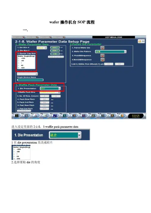
wafer操作机台SOP流程
一.
进入设定里面的2-1-8,3.waffle pack parameter data
1在.die presentation里改成硅片
2.选择要贴die的角度
二.
在焊接页面把选项打开1硅片图要打开
2推顶器要打开
三.
装上硅片扩张器后,进入设定2-3-6。
点击卸载X Y T
通过点击扩张器旋转运动来控制扩张器的角度。
设置硅片扩张器的数值,按照上图的数值来设定。
通过点击扩张器旋转运动来控制硅片工作台的卡扣能与扩张器的的卡槽对应。
四.
进入设定界面2-1 点击硅片映射
进入硅片映射
选择路径名找到MAP资料选择MAP名称点击栽入像图
可调整MAP图的角度点击设定参考芯片进入MAP设定
点击参考点图像坐标,在MAP图上找一个比较容易认识的die做识别坐标。
点击参考点工作台位置,把硅片台移动到在MAP图上做识别坐标的位置。
点击设定校准,找一颗die做识别MAP的PR。
五
点击推顶器上生高度(从参考点)设置顶针的高度可用移动遥杆来控制顶针高度数值。
点击Ejector cap Reference Level 是教读吸咀到顶针的高度。
dopod C858 用户手册2006.12多普达通讯有限公司敬告:在操作本机之前请阅读下述内容在提示不能使用手机的场合,如医院、飞机机舱内、加油站、怕无线干扰的地方,请您关闭本设备!在飞机上除了打开飞行模式外,请关闭整个设备的电源。
插入SIM 卡时请确保外接电源已经断开,且SIM 卡放置到位。
第一次充电请充满8小时。
在充电的过程中,请不要从手机上取下电池,以防损伤设备。
本机型不具有防水功能,请您注意防水,保持手机的干燥。
如果自行打开或者损伤外壳将不再享受保修服务。
请使用由多普达公司指定的附件和认可的第三方软件,否则如果设备出现问题多普达公司将不承担任何责任。
请注意保护好手机屏幕,防止磨损或挤伤。
此类损伤均被认为是人为损坏。
请及时备份数据!多普达公司不承担因产品故障导致信息丢失而造成的一切直接或间接损失。
尤其在更换电池前更加需要备份数据。
本设备中包含有一个锂电池电池。
如果电池处理不当,将会有着火和燃烧的危险。
不要分解、挤压、刺穿电池,不要短路电池外部的接头,更不要将其投入火中或者水中。
不要试图打开或者维修该电池,只能使用产品指定的电池来进行更换。
请正确处理电池不要随意丢弃。
由于软件版本更新而造成界面和功能变更,恕不另行通知。
友情提示:亲爱的用户,由于多普达智能手机内含一套完整的电脑系统,类似于个人电脑的系统架构和运行规则。
1.充足的系统内存,将有助于手机良好高效的运行,所以建议您每天至少重新启动手机一次,以彻底清空内存,恢复系统至最佳状态。
2.请正确合理地使用您的手机内存,建议您不要同时运行过多的程序,否则将使手机运行速度变慢。
如发生此类情况,建议您重新启动手机,即可恢复如初。
注意:对于预装或捆绑于本机中的任何游戏、应用程序包括相应文件(以下简称软件),或通过本机取得的视听资料、内容、服务以及相关文件资料,包括但不限于任何图像、照片、动画、录像、录音、音乐、文字,(以下简称服务)皆由相应软件/服务提供商(以下简称提供商)负责其合法、真实和准确,并由提供商保证不违反国家法律、法规、公共道德及侵犯任何第三方之合法权益。
苏州三洋机电有限公司操作员工培训教材文件编号:SJDD023B05二OO七年三月操作员工培训教材遵循GB/T19002-1994 ISO9001.2000“质量体系生产,安装和服务”的标准,使公司每个员工对本职工作做到有章可循,程序文件中指出:操作员工必须按本岗位,本职的职责遵章执行。
以下分别叙述操作员工应遵守规定的有关职责:1.操作员工的职责(1)严格按照作业指导书要求,具体操作:(2)作好设备的点检及维护保养工作,做好点检记录。
2.生产过程中的作业指导书作业指导书在每道工序中都有着不同要求。
每个操作员工应该遵守“作业指导书”规定的操作顺序,注意事项(安全,质量)。
按照公司生产制造过程,简要划分为发电机装配,摩电灯装配和冲压零件制造。
3.1(工位共有32个,未包括折倒机构装置的4个)工位新增轮毂线工位24个。
在发电机装配中,特殊工序为:线圈绕线,磁钢充磁。
其它工序则遵循:“作业指导书”规定。
3.1.1特殊工序的相关工序要领为确保特殊工序监控在绕线和充磁的相关工位操作必须保持质量的稳定:A:线圈绕线:(a)线圈两端出线长度搪锡;(b)铜铆钉铆接平整,引线不能破损漆膜;(c)A,B芯铆接无污物,引线可靠接触。
B:磁钢充磁:(a)转轴轴径处无损伤:(b)轴,套筒,磁钢三者配合必须按实际要求尺寸胶合;(c)三者配合8小时后粘接强度100Kg3.1.2其它工序和电机装配测试(a)机壳压入轴承后的注油量目测和两端的同轴度;(b)经充磁后的磁钢,装入机壳后用摩擦轮,螺帽固定,保持150N的旋紧力矩;(c)操作杆,弹簧,定位片,支架装入机壳后,在固定机盖时用M3×16螺钉旋入保持30—70N的旋紧力矩;(d)发电机的最终测试:机壳与盖间隙〈0.3㎜;轴向窜动0.03—0.3㎜;操作杆锁紧力:平行式:15—40N电压:6V±0.3V3.2摩电灯装配工序要领(a)灯壳与接触片,托架铆接平整,铆接强度保持在20—50N;(b)灯盖与灯壳的拧紧强度50—100N(M4×18螺钉);(c)点灯测试中间不能有黑影,电源线穿入端子弹簧后可挂1㎏重物不脱落;(d)摩电灯外观目测无擦伤,灯盖内无杂物,镀锌件良好,Ф6的铆接孔须使M6螺栓通过。
ad830培训AD830培训:全面提升专业技能与职业素养一、引言在当今竞争激烈的职场环境中,专业知识和技能的提升成为了每位从业者必须面对的课题。
AD830培训课程作为一门旨在提升专业技能与职业素养的综合性培训项目,为广大从业者提供了一个全面提升自身能力、拓展职业发展空间的有效途径。
本文将详细介绍AD830培训的课程设置、培训目标、培训方式等内容,帮助您全面了解并充分利用这一培训资源。
二、AD830培训课程设置AD830培训课程分为四个模块,分别为专业技能、职业素养、团队协作与沟通能力、创新与领导力。
每个模块下设有若干子课程,共计20门课程。
课程内容涵盖了职场必备的核心知识与技能,旨在帮助学员全面提升自身能力。
1. 专业技能模块:包括市场营销、财务管理、人力资源管理等专业课程,旨在提升学员在各自领域的专业素养,增强职场竞争力。
2. 职业素养模块:涵盖职业规划、时间管理、商务礼仪等课程,帮助学员树立正确的职业观念,提升职业素养。
3. 团队协作与沟通能力模块:通过团队建设、有效沟通、谈判技巧等课程,培养学员的团队协作精神和沟通能力,提高工作效率。
4. 创新与领导力模块:包括创新思维、领导力培养、战略管理等课程,激发学员的创新能力,培养具备领导潜质的优秀人才。
三、AD830培训目标1. 提升专业技能:使学员掌握所在领域的核心知识与技能,提高工作效率,增强职场竞争力。
2. 培养职业素养:帮助学员树立正确的职业观念,养成良好的职业习惯,提升个人综合素质。
3. 增强团队协作与沟通能力:培养学员的团队协作精神和沟通能力,提高团队执行力。
4. 激发创新思维与领导力:激发学员的创新能力,培养具备领导潜质的优秀人才,为企业发展注入活力。
四、AD830培训方式1. 面授课程:采用线下授课方式,学员可现场聆听专家讲师的精彩讲解,与讲师互动交流,解答疑难问题。
2. 在线课程:通过线上平台,学员可随时随地学习课程,充分利用碎片化时间进行自我提升。
目录第一章加工中心设备操作基础 (2)第二章加工中心程序基本知识 (16)第三章数控车床编程与操作基础 (35)第四章数控设备日常保养规范 (51)第五章钻床设备操作基础 (52)第六章量检具使用方法 (58)第七章安全生产操作规范 (64)附录刀具基础知识(车刀、镗刀、铣刀、复合刀、钻头、丝锥)……………第一章加工中心设备操作基础第一节机床操作面板机床操作面板由CRT/MDI面板和两块操作面板组成。
1. CRT/MDI面板如图1-1所示,CRT/MDI面板有一个9〞CRT显示器和一个MDI键盘组成,CRT/MDI 面板各键功能见表1-1。
图1-1 CRT/MDI面板表1-1 CRT/MDI面板各键功用说明2. 下操作面板如图1-2所示,面板上个按钮、旋钮、指示灯功用说明见表1-2。
图1-2 下操作面板表1-2 下操作面板各开关功用说明3. 右操作面板如图1-3所示,面板上各开关功用说明见表1-3。
图1-3 右操作面板 表1-3 右操作面板各开关功用说明第二节手动操作与自动操作1.表1-4 手动操作的方法2.自动操作自动操作的方法见表1-5。
表1-5 自动操作的方法第三节加工程序的输入和编辑表1-6 加工程序的输入和编辑方法第四节刀具偏置如果NC程序使用刀具半径补偿指令,在运行此程序之前必须通过刀具偏置的方法设定刀具半径补偿值,还可以通过刀具偏置的方法调整刀具半径的补偿量。
刀具偏置有绝对值方式和增量值方式两种输入方法,采用哪一种输入方式由机床的内定参数设定。
1. 绝对值方式输入刀具偏置量输入刀具偏置量的方法,按刀具偏置功能键MENU OFFSET ,在CRT上显示刀具偏置页面,按↓PAGE钮可以调整显示页面。
1)选定刀具偏置号选定刀具编置号有二种方法,一种方法是按CURSOR↓或↑光标键,移动光标至要找的刀具偏置号处,如果连续按光标按钮,光标在屏幕上顺序移动,直至找到需要的刀具偏置号(如果移动光标超出这一页面,将进入下一页面);另一种方法是按NO Q P按钮,输入要找的刀具偏置号,再按INPUT按钮,从而选定需要的刀具偏置号。