实时视频设计文档说明书
- 格式:docx
- 大小:156.66 KB
- 文档页数:8


视频监控平台概要设计说明书文件更2改摘要1 :目录1. 弓I言 (5)1.1. 编写目的 (5)1.2. 背景 (5)1.3. 术语 (6)1.4. 预期读者与阅读建议 (6)1.5. 参考资料 (7)2. 总体设计 (7)2.1. 设计目标 (7)2.2. 运行环境 (8)2.3. 网络结构 (8)2.4. 总体设计思路和处理流程 (9)2.5. 模块结构设计 (13)2.6. 功能需求与程序模块的关系 (22)2.7尚未解决的问题 .......................................... 错误!未定义书签。
3. 接口设计 (48)3.1. 用户接口 (48)3.2. 外部接口 (52)3.3. 内部接口 (65)4. 界面总体设计 (81)5. 数据结构设计 (84)6. 系统安全设计........................................... 错误!未定义书签。
6.1. 数据传输安全性设计...................................... 错误!未定义书签。
62 .......................................................................................................... 应用系统安全性设计错误!未定义书签。
63 .......................................................................................................... 数据存储安全性设计错误!未定义书签。
7. 系统部署(可选) (84)1.引言1.1. 编写目的本文档的主要读者为公司决策管理层、质量部、策划部、开发部等有关人员,为后面的系统开发提供指导和保障。


目录第1章课程设计构思和作品内容 (1)第2章课程设计步骤 (1)第3章课程设计总结 (5)参考文献 (8)第1章课程设计构思和作品内容一、构思:我制作的课设题目是《北京城市形象宣传片》,我个人很喜欢北京这个城市,所以我决定搜索资料,做一个北京的城市宣传片。
我想对城市的宣传,主要需要体现一个城市的特色、历史渊源、文化底蕴、标志建筑等。
因此,我在视频、图片素材的选择上,尽量挑选有背景特色的素材,如天安门、国庆阅兵、长城、故宫、北京大学、京剧、天安门升旗仪式、奥运会等。
因为北京是祖国的首都,是经济政治文化的中心,所以,一些中国特色的事物同样能够表现北京的特色,如水墨画、武术、太极等。
北京是一座国际化的大都市,是和谐融合中西方文化的典型代表城市,因此,我想选用一些中西文化的碰撞来表现这一主题。
二、内容:开头是一个放大镜在地图上寻找北京,随着“北京”二字的不断放大,进入宣传片的主要内容。
随着强节奏的京剧鼓点,一个个身姿曼妙,功夫了得的京剧演员出场了。
随着音乐的变化,大门开启,一幅幅北京古代标志建筑和现代人的生活穿插在一起,表现了北京是一个古今融合的城市。
又是一段强节奏的,令人激昂振奋的音乐,画面中出现了国庆阅兵的壮观画面,中间穿插着北京奥运会留下来的标志建筑——鸟巢和水立方。
接下来表现的是北京市民的文化和艺术。
舞蹈、武术、水墨画、民间手工艺品,这些都是北京的特色和北京市民积极向上风貌的体现。
芭蕾舞、歌剧与中国舞蹈、古代宫殿与现代高楼大厦,外国游客与北京市民,一个个鲜明的对比,都体现出北京是一座融合东西方文化、融合古今文化、富有历史和文化底蕴的,现代化的大都市。
第2章课程设计步骤一、确定主题:我个人喜欢北京这个城市,因此我想要做一个宣传片来宣传北京,同时也希望借助制作宣传片的机会,加深对北京这个城市的了解。
二、搜集素材:我在优酷视频网上下了一些北京的城市形象宣传片、北京申奥宣传片和北京奥运会宣传片。
同时,我还在百度网上搜集了一些具有北京特色的图片,一些北京的标志性建筑和标志性事件。

实时视频直播平台设计方案
一、概述
随着互联网的快速发展,视频直播已经成为一种非常流行的娱乐和社
交方式。
实时视频直播平台允许用户通过互联网将自己的活动或内容实时
传输给观众。
本文将提供一个实时视频直播平台的设计方案,包括架构、
功能、用户界面等。
二、架构
1. 前端架构:用户界面设计应简洁、直观。
使用HTML、CSS和JavaScript等技术实现页面布局和交互效果。
可以采用响应式设计,适
应不同屏幕尺寸的设备。
2. 后端架构:实时视频流的传输和处理需要强大的服务器端技术支持。
可以选择使用Node.js等服务器端技术来处理用户请求,同时结合WebSocket或WebRTC等技术实现实时视频传输。
三、功能
1.用户注册和登录:用户可以注册一个账号,并使用账号登录平台。
2.视频直播:用户可以选择开始自己的直播,并将视频内容实时传输
给观众。
3.观众互动:观众可以通过平台提供的聊天工具实时与主播进行互动,包括发送消息、送礼物等。
4.视频存储和分享:平台可以将用户的直播视频保存在服务器上,并
提供分享功能,方便用户将视频分发到不同的社交平台上。
5.弹幕功能:为了增加观看体验,平台可以支持弹幕功能,允许用户在观看直播过程中发送弹幕消息。
6.视频回放:平台可以提供视频回放功能,允许用户在直播结束后重新观看直播过程。

基于目标检测算法的实时视频监控系统设计摘要:随着科技的不断发展,实时视频监控系统的需求也越来越大。
本文旨在设计一个基于目标检测算法的实时视频监控系统,以提高监控效率和准确性。
通过综合运用计算机视觉、深度学习和图像处理等技术,我们将实现对视频流中感兴趣的目标进行实时检测和跟踪,并通过实时报警系统对异常事件进行预警处理。
该系统具有较高的可靠性和准确性。
1.引言实时视频监控系统在各种应用场景中扮演着重要角色,如智能交通系统、安防系统等。
然而,传统的监控系统存在监控效率低、准确性不高的问题。
基于目标检测算法的实时视频监控系统能够有效地解决这些问题。
2.目标检测算法及其原理目标检测算法是计算机视觉领域最为关键的技术之一。
本文采用了Faster R-CNN算法作为目标检测算法。
Faster R-CNN算法是一种基于深度学习的目标检测方法,它利用深度神经网络实现对视频流中的目标进行快速而准确的检测。
3.实时视频监控系统设计(1)视频流获取:使用摄像头或者网络视频流作为输入源,获取实时视频流。
(2)视频预处理:对实时视频流进行处理,包括图像增强、去噪、裁剪等操作,以提高目标检测算法的准确性。
(3)目标检测和跟踪:使用Faster R-CNN算法对视频流中的目标进行实时检测和跟踪。
该算法能够在较短的时间内完成对多个目标的检测和跟踪,并给出目标的位置信息。
(4)异常事件检测:对目标检测结果进行分析和判断,通过设定的规则筛选出可能的异常事件。
例如,当监测到人员闯入禁止区域时,系统能够自动发出报警信号。
(5)实时报警系统:对异常事件进行实时预警处理,如声音报警、短信报警等,以及向相关人员发送警报信息。
(6)系统界面设计:为用户提供友好的系统界面,便于观察实时监控视频流、查看异常事件等。
4.实验与结果本文根据设计的实时视频监控系统开展了一系列实验,得到了如下结果:(1)在不同场景下,系统能够准确地检测和跟踪视频流中的目标。

Professionally approved products.User ManualFULL HDVideo-BlackboxArticle no: 8802201IndexA.Feature Description (3)B.Specification (4)C.Accessories (4)D.Schematic Diagram of The Installation Steps (5)E.Product Function Introduction (7)F.SD Card Installation (8)G.OSD Menu (9)H.Remote Controller Description (10)I.Recording / Stop Recording (11)J.The RS component Player (12)1. Operation icon introduction (12)2. Capture (12)3. Configuration (13)4. File backup (15)5. Playback (16)6. Progress bar (16)7. Play speed (17)8. Volume control (17)9. G-SENSOR (17)10. Format (17)K.Estimated Recording Time (19)L.Appendix: Bright and dark spot on the LCD (20)A. Feature Description⏹Full HD real-time recording (with H.264 compression technology)⏹105° Wide-angle CMOS Lens⏹ 2.5”TFT LCD⏹GPS sensor⏹Record video with sound inside and outside the car⏹Compatible with SDHC Card up to 32GB⏹Automatic loop recording⏹Emergency recording, file save to separate area to prevent overwritten⏹Built-in GPS for tracking speed and position⏹Built-in G-Sensor, to automatically record footage in case of an accident⏹Made in Taiwan, with a 1 year warrantee – the longest of any dash-cameraB. SpecificationC. AccessoriesAdapter / IR remote control / Software CD / Bracket / 3M sticker / 8 GB Class 10 SDHC CardD. Schematic Diagram of The Installation Steps1. Install the device on the windshield using bundled 3M or suction cup mount2. Find the optimal position of device on the windshield3. Adjust to the appropriate recording angle4. Plug in the DC5V Power Supply5. Plug in the Cigarette chargerSticker Adhesive SpotStick-Holder Type6. Diagram of recommended device installationNotice Best locationCigarette adapterE. Product Function IntroductionSD card SlotDC5VPower inputLensF. SD Card Installation(1). To format the memory card; please refer to the other chapter “Formatting thememory card” for more detail.G. OSD MenuPressto open the OSD (On Screen Display) menu shown below:1. Video standard: Click to choose NTSC / PAL2. Time setting: Click to adjust clock3. Display sleep: Click to set delay time of display sleep4. Firmware Version:to show firmware versionNTSC / PAL Time setting Display sleep Firmware versionH. Remote Controller DescriptionDisplay On/Off Force Recording Volume Down Stop Voice Recording StopPlayPauseUp / Down Left / RightSpeaker On/OffVolume UpI. Recording / Stop Recording1. Power On/RecordingThe device automatically starts on car power on.Please allow 30 sec. for recording to start.2. Power Off/Stop recordingWhen the car power is off, the device will stop recording video and sound. You can take out the memory card and insert it in your computer to view the video.3. IndicationBlinking red light indicates recording.Fast blinking red light indicates activation of the secure recording feature.J. The RS component PlayerThis software requires DirectX 9.0 or above installed on your PC.1. Operation icon introductionBack to previous filePrevious imageRewardPauseStopPlayNext imageNext footage2. Capture: Create a snapshot of current video frameYou can save a frame of your footage during playback of footage.Click the button to take a snapshot of the current video frame.The following window is shown, with the image captured shown on the right side. Snapshots are saved as Bitmap images (*.bmp) in the application directory /Snapshot sub-folder.(Snapshot file)3. Configuration: configure default settingsBefore using the first-time connect the SD Card to your computer to format the SD card. Configure the desired video format (NTSC or PAL). Afterwards, you caninsert the SD card into the device and start recording.Default quality is highVideo Frame25(PAL) / 30(NTSC)Encrypt the SD card to prevent unauthorized access.Password must be under 15 characters in length, forexample: 123456789123456After setup, the password is required for playback,configuration and formatting of the SD card.★Remember the password. Without passwordfootage cannot be retrieved.You can set a password for playback on the built-indisplay of the device.The G-Sensor can detect impact and active thesecure recording function automatically.Set the sensitivity here. Choose Car or Truck. Thesensitivity has 5 options: Off / Very low / Low /Normal / High / Very high.Turn audio recording on/off.4. File backup:click to backup footage.Step1. Choose the source of the memory card.Step2. Choose the footage you want to backup.Step3. Choose the target file format and the start and end points.File format(1) Proprietary file format*.sd format(2) AVI video (*.avi)AVI format★Note:To keep G-Sensor data, use proprietary format.AVI format doesn’t not contain G-sensor data (onlydate/time/image/sound)Step 4. Set the backup folder: default is C:\BlackBoxStep 5. Start backup5. Playback: Open file6. Progress bar:Use the mouse and drag the car icon to view a particular time of the footage7. Play speed:Choose 2, 4 or 8 times normal playbackor 1/2, ¼ or 1/8 times normal playback.8. Volume control:Click +/- to adjust volume.9. G-SENSORThe integrated G-Sensor can detect impact and record 1-3 minutes of footage automatically. This footage is protected to avoid files being overwritten.10. Format:Format memory card/Langue setting(1) X: Detect vehicle horizontal change.(2) Y: Detect vehicle vertical change.(3) Z: Detect vehicle front/back change.Warninga、「Format」SD-CardWhen you use an SD card for the first time, it recommended you format the SD-Card.b、「Restore」SD-CardIf you have a back up of your SD-Card, you may restore it’s contents using the restore function.c、Language settingYou can change the change the language setting.*Note: Changes will take effect after rebooting software.d、Current VersionK. Estimated Recording TimeNote: The chart below of estimated recording times is for reference only. The length ofrecording may vary according to recording conditions.L. Appendix: Bright and dark spot on the LCDQ: What is a bright/dark spot?A : Bright spot: An abnormal bright spot, against a dark background, is called a “brights pot”Dark spot: An abnormal dark spot, against a multi-colored background (excluding dark backgrounds), is called “dark spot”Indication of bright and dark spots(a) No bright spot is allowed in Area A,only a single dark spot(b) The maximum amount of bright spotsand dark spots allowed in Area B istwo of each(c) The maximum total amount of brightand dark spots in Area A and B arethree or less Diagram of areas A and BNotice。

视频设置说明书模板1. 概述本视频设置说明书旨在帮助用户正确、准确地设置和调整视频设备,以获得最佳的视觉体验。
以下是各项设置的详细说明。
2. 设备连接请按照以下步骤连接视频设备:1) 将视频设备与显示设备(如电视、电脑显示器)通过HDMI、VGA或其他兼容接口进行连接;2) 确保连接稳固,接口没有松动或杂音;3) 接通电源。
3. 分辨率设置视频设备的分辨率设置将直接影响到图像的清晰度和细节展示。
请根据以下步骤进行设置:1) 进入视频设备的设置菜单;2) 找到“显示”或“图像”选项;3) 选择“分辨率”;4) 根据显示设备的支持情况,选择最适合的分辨率;5) 确认保存设置,并退出菜单。
4. 色彩调整正确的色彩调整能够让图像色彩更加真实、逼真。
根据个人喜好,您可以按照以下步骤进行色彩调整:1) 进入视频设备的设置菜单;2) 找到“显示”或“图像”选项;3) 选择“色彩调整”或“色彩设置”;4) 根据您的个人喜好,调整亮度、对比度、饱和度等参数;5) 确认保存设置,并退出菜单。
5. 音频设置音频设置对于观看视频同样重要。
请根据以下步骤进行音频设置:1) 进入视频设备的设置菜单;2) 找到“音频”选项;3) 根据您的需求选择声道模式(立体声、环绕声等);4) 根据个人喜好调整音量大小;5) 确认保存设置,并退出菜单。
6. 其他设置根据不同的视频设备,可能还包括其他设置项,如语言选择、屏幕比例调节等。
请根据您的设备说明书来进行相应的设置。
7. 故障排除如果在使用过程中遇到视频无法正常显示、画面模糊等问题,请尝试以下解决方法:1) 检查视频设备和显示设备之间的连接是否稳固;2) 检查设备的电源是否正常;3) 调整分辨率和色彩设置,确保其适合显示设备;4) 重新启动视频设备和显示设备。
如果问题仍未解决,请联系售后服务中心进行进一步的故障排查和维修。
8. 使用注意事项在使用视频设备的过程中,请注意以下事项:1) 避免长时间连续使用视频设备,以免过热损坏设备;2) 温度适宜的环境更有利于设备的正常工作;3) 尽量避免将液体或其它物质溅到设备上;4) 定期清理设备和连接线,保持通风良好。

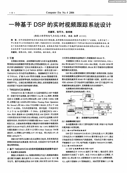
Design of a High Definition Video Communication System in Real-time NetworkLiu YunfengUniversity of Chinese Academy of SciencesBeijing, ChinaInstitute of Optics and Electronics, CASChengdu, ChinaPeng Xianrong, Jin Zheng Institute of Optics and Electronics Chinese Academy of SciencesChengdu, ChinaAbstract—This paper presents the design of a high definition video communication system with real-time performance in the network. In order to process and transmit the high definition video, the design combines FPGA and SOC, follows the H.264 video coding compression. The FPGA realizes the high–speed video acquisition via Cameralink interface, and convert the raw image to ITU-R BT.1120 stream. The SOC contains CPU and Codec, it compresses the BT.1120 stream to H.264 steam and transmit the stream in the network. The low-delay rate control algorithm can limit the bitrate in a very low level. The result shows that the system reduces bandwidth and lowers the latency, the design is adaptable to the real time environments.Keywords-FPGA; H.264; ITU-R BT.1120; Low latency;I.I NTRODUCTIONIn recent years, there is an urgent demand of the high resolution image processing in the aerospace, opto-electronic detection and other fields [1], such as Full HD (High Definition) video. The HD video (1920 pixels x 1080 pixels 30 frame per second) has huge data, and is difficult to be processed on the traditional image processing platform. So the video compression is needed. H.264 as the new generation video coding standard, has greatly improved the image quality and bitrate control. This paper uses the FPGA and SOC (System On Chip) with hardware and software combination, designs and implements a network video communication system on the H.264 coding algorithm.II.S YSTEM H ARDWAREThe system contains the CCD camera, FPGA, SOC and some peripheral hardware. The camera transmits the images by the CameraLink interface. The FPGA is Spartan-6 [2], it processes the digital image, converts the image to ITU-R BT.1120 video stream [3], and then, transmits the stream to the SOC. The SOC is MG3500 [4], it contains a ARM9 CPU and a H.264 codec, the codec encodes the video to H.264 stream in real time, the CPU transmit the stream in the network at last. Fig.1 shows the system architecture.Figure 1. The hareware frameworkIII.FPGA D ESIGNA.Video acquistionHigh definition digital video is transmitted from camera to FPGA via CameraLink interface, and then buffered in the DDR2 SDRAM. Spartan-6 has the specialized MCB core for the DDR access, DDR2 SDRAM can read and write data conveniently. In order to balance the speed of the image data input and output, one frame must be buffered at least; the ping-pong operation is also used to ensure the image integrity. So the system design use DDR2/800MHz as the frame buffer for the high speed image data access, and open two frame buffers for ping-pong operation.The CCD pixels are preceded in the optical path by a color filter array (CFA) in a Bayer mosaic pattern, in order to get real color images, the raw image should be processed in the pipeline including demosaicing [5], auto white balance and auto gain control [6].After that, the Bayer pattern image is converted to RGB image.B.BT.1120 conversionAfter all the image processing above, the digital image should be converted to BT.1120 stream.The BT.1120 is the recommendation of digital interfaces for HDTV studio signals. It complies with the characteristics described in Recommendation ITU-R BT.709 [7]. BT.709 contains some HDTV studio standards to cover a wide range of applications including Common Image Format (CIF) system which has 1125 total lines and 1080 active lines. The standards contain opto-electronic conversion, picture characteristics, picture scanning characteristics, signal format and analogue representation. BT.1120 also follows these standards, and then contains more such as bit-serial data format and transmission format.BT.1120 video interface supports 10-bit and 8-bit video data transmission, the video data format can be RGB 4:4:4 or YCrCb 4:2:2. First, the color space should be converted from RGB to YCbCr. The raw digital RGB color has 3 components including Red, Green and Blue. Each component has a value between 0 and 255, corresponding to 8-bit quantization. In accordance with BT.1120 recommendation, the value should be normalized as in (1)255/,255/,255/R E G E R E R G R === (1)YCbCr is not an absolute color space; rather, it’s a way of encoding RGB information. It contains the luminancecomponent(Y), blue-difference component (B-Y) and red-difference component (R-Y). In accordance with BT.1120 recommendation, the YCbCr is derived from RGB accordingto the following transform:0.07220.7152 0.2126 R B G Y E E E E ++=()8556.19278.07152.02126.09278.05.0B G R Y B CB E E E E E E +−−=−= (3)()5748.10722.07152.07874.07874.05.0B G R Y R CR E E E E E E −−=−= (4) After the transform, the signal should be quantized. In BT.1120 recommendation, as 8-bit quantization, the Y component has 220 steps, the value 0 is mapped to 16; the Cr and Cb components both have 255 steps and 0 is mapped to the median, 128. So the quantized signal is derived as follows:()5.16219int +=Y Y E D (5)()5.128224int +=CB CB E D (6) ()5.128224int +=CR CR E D (7)D Y , D CB , D CR respectively represents the quantized digital YCbCr signal. For FPGA to achieve, fixed-point decimal arithmetic can be multiplied by a factor into integer arithmetic. All the values in (5)~(7) are multiplied by 1024, the new transform is (8)~(10):1024187 6296316896Y D R G B =+++ (8)131584450347--1031024++=B G R D CB (9) 131584414094501024+−−=B G R D CR (10)After the color space converted, the signal should be sampled. ITU-R BT.1120 describes the YCbCr signals in4:2:2 sampling rate. This system uses the 8-bit color space,so that each pixel has 16 bit data composed of achrominance(C) component and a luminance(Y) component.In accordance with the bit-parallel interface in BT.1120, Cband Y are transmitted in odd numbers of pixel clock; Cr and Y are transmitted in even numbers. The sequence isrepresented as:(Cb 1 Y 1) (Cr 1 Y 2) (Cb 3 Y 3) (Cr 3 Y 4)… The FPGA can convert the image from RGB to YCbCr in parallel processing rapidly, the conversion can be completed in two timing cycles while nine DSP multipliers are used. The data path is shown as Fig. 2.Figure 2. YCbCr conversion.ITU-R BT.1120 digital interface contains only the videodata signal without a separate control signal. it use the timing reference codes to identify the line and frame. There are two timing reference codes embedded into video data stream, one at the beginning of each video data block(start of active video, SAV) and the other at the end of each video data block(end of active video, EAV). These codes are contiguouswith the video data, and continue during the field/frameblanking interval.Each code consists of a four-word sequence. In the 8-bit implementation, the bit assignment of the word is given in Table I. The first three words are fixed preamble and the fourth word carries the information that defines fieldidentification (F), frame blanking period(V), and line blanking period (H). TABLE I. B IT A SSIGNMENT F OR V IDEO T IMING R EFERNCE C ODES WordBit number765 4 3 2 10First 111 1 1 1 11Second 0000 0 0 00Third0000 0 0 00fourth1FVH P3 P2 P1P0The bits F and V change state synchronously with EAV at the beginning of the digital line. The value of protection bits, P0 to P3, depends on the F, V and H as shown in Table15. The arrangement permits one-bit errors to be correctedand two-bit errors to be detected at the receiver, as shown inTable II.TABLE II. P ROTECTION B ITS F OR SAV/EAVSAV/EAV bit status Protection bitsF V H P3 P2 P1 P00 0 0 0 0 0 00 0 1 1 1 0 10 1 0 1 0 1 10 1 1 0 1 1 01 0 0 0 1 1 11 0 1 1 0 1 01 1 0 1 1 0 01 1 1 0 0 0 1In order to implement the timing reference codes on FPGA, The Table II should be stored in the ROM with 4-bit width and 8-bit depth. The bits F,V and H are mapped to the ROM address, the protection bits are stored in the corresponding address. When encoding the timing reference codes, the bits are read from the ROM address and then combined with it.IV.L OW L ATENCY R ATE C ONTRLThe SOC can encode the BT.1120 stream to H.264 data. Under the prerequisite of image quality, this paper designs a low-delay rate control algorithm to reduce the transmission bandwidth and lower the delay.The rate control algorithm uses data on the size of past frames to estimate the size of future frames. It uses its algorithm to decide if the size of future frames must be changed in order to meet performance requirements such as bitrate and latency.Rate control algorithms are usually classified as VBR (Variable Bit Rate) and CBR (Constants Bit Rate). CBR generally means maintaining the specified bitrate over time. VBR generally means that the rate control is allowed to generate a bitrate much lower than specified when the image is easy to encode. This is intended to prevent wasting bits, if a lower bitrate can achieve a high quality. This paper uses a VBR algorithm.Low latency encoding is the most difficult case for the rate control, since it is typically used for network streaming. Network streaming usually requires a low transfer rate due to limited bandwidth, so this produces the rate control’s worst case scenario of low latency plus low transfer rate. Therefore, this section refers to "low latency" encoding but actually means low latency plus low transfer rate.A.Rate comtrolOn MG3500, the algorithm set the slice QP (quantization parameters) value in order to control the long term bitrate. In AVC encoding, the QP value controls the quantization of all coefficients in the frame [8]. More quantization (a higher QP value) means fewer bits per frame, and less quantization (a lower QP value) means more bits per frame. The QP values range from 0 to 51. For the VBR application, the minimum QP value is set to 20.The rate control use separate parameters for the bitrate and for the transmission rate. The bitrate is an approximate target for the size of the bitstream. The transfer rate is an absolute upper limit on the size of the bitstream. The transfer rate controls the fluctuations of the bitrate.If the transfer rate is set much higher than the bitrate, then the bitrate may rise very high for short periods. If the transfer rate is set close to the bitrate, it places a limit on how high the bitrate can increase within a short period.The transfer rate represents the rate at which data can be transferred to the decoder. In the case of network streaming, the transfer rate should be set to approximately the maximum bandwidth available. The transfer rate should not be set low unless this is required. A lower transfer rate limits the rate control when it is choosing the short term bitrate. This will generally result in a long term bitrate, because the rate control will tend to produce smaller frames in order to avoid exceeding the transfer rate. The risk of frame drops is also increased.Recommended transfer rates are 1.5 x bitrate for low latency applications.B.Low latencyThe rate control includes explicit setting parameters for the target latency. Technically, this is the amount of data the decoder is expected to buffer before starting playback. In reality, it affects the overall latency between the encoder and the decoder. The rate control’s latency setting does not control the overall latency, which depends on encoder and decoder settings and the network delay. However, the rate control must be set to support this latency or it will occasionally produce frames which are too large, and cannot be transmitted to the decoder when it requires them. The latency setting can only be understood in combination with the transfer rate setting above. The latency controls the number of frames which can be buffered up between the encoder and the decoder, and the transfer rate controls how fast those frames are actually transmit. The two of these together control the size of the frames.If the latency is low but the transfer rate is very high, only a few frames can be buffered but their size does not matter. Even if they are very large, they can be transmitted before a new frame is encoded and there will always be a small number of buffered frames. But if the transfer rate is low but the latency is very high, many frames can be buffered. A few large frames will be averaged with many smaller frames, and they will not exceed the buffering limit.Only if both latency and transfer rate are low does the rate control’s behavior change substantially. As latency and transfer rate are reduced, the actual bitrate will fall further below the specified bitrate. The rate control cannot use the full bitrate, or it will risk generating a frame which is too large to transmit to the decoder on time. So the recommended latency for the network is 4 frames(133ms).the H.264 coding chose high profile and level 4.1 feature, using the IP GOP (group of Pictures) structure [8] with only I-frame and P-frame ,the B-frame is not used to lower the decoder’s latency.V. N ETWORK T RAMSMISSIONAs a video network communication system, network transmission is also very important. After encoding, the H.264 stream is transmitted in the network over TCP/IP.Video communication has high real-time requirements. In order to ensure that the transmission of the image will not obviously delay the system in the unknown network, UDP protocol is used in the transport layer for network communications.Considering the complexity of the data packets out of order in the transmission network, this will bring some error in real-time decoding to affect the image quality, the system has completed the RTP (Real-time Transport Protocol) protocol [9]. RTP is an application layer protocol, which also use UDP in the transport layer, not a connection-oriented TCP.In the data packets to be transported, there is a RTP header that contains some important information such as the data sequence numbers and timestamps, Timestamp is the description of the packet time synchronization information, it helps the critical data be restored to the correct chronological order, which requires that the sender timestamps increase continuously and monotonically. So that at the receiving end, as long as a certain data cached, the video data can be sorted and restored in accordance with the normal sequence.According to the size of the receive buffer, using the RTP transmission will bring a little certain delay, but a certain improvement in image quality at the same time, which doesn't influence the real-time.RTP and UDP are point-to-point transmission, in order to meet some one-to-many transmission requirements, the system also implements RTSP (the Real Time Streaming Protocol) protocol stack with the Client (decoder) / Server (encoder) model, it's a text-based protocol for client and server to establish and negotiate the real-time streaming.RTSP is also an application layer protocol, which is located above RTP. This protocol doesn’t transmit the data, it only control the states of the stream. The system still uses the RTP/UDP to transmit the stream at the transport layer.VI. E XPERIMENTSThe design described in this paper is successfully used in a opto-electronic system, Fig.3 shows the bitrate curve in the corresponding experiments.We set the video bitrate of 6000kb/s, the long term rate is stable. In the static scene, the bitrate is about 5000kb/s, especially in some low complexity scene, the rate is below 4000kb/s; in the motion scene in a short while, the rate increases to 6000kb/s.The whole latency is about 300ms, when the videodisplays in the remote decoder.Figure 3. The Bitrate changes.VII. C ONCLUSIONThe paper designs a real-time full HD video communication system which combined FPGA and SOC, and then introduces in detail the design of each module including BT.1120 Stream conversion, low latency rate control and network transmission. The result shows that the system has the following advantages. One is high real time, the H.264 codec can encode the video at high speed with the low latency rate control algorithm. The other one, the FPGA have rich resources inside, and can achieve the required functions on different demands.R EFERENCES[1] W. Chen, P. Chen, W. Lee and C. Huang, “Design andImplementation of a Real Time Video Surveillance System with Wireless Sensor Networks,” IEEE Vehicular Technology Conference, May 2008, pp. 218-222,.[2] Xilinx Corporation. “Spartan-6 FPGA Memory Controller UserGuide,” Aug. 2009.[3] ITU-R. “Digital interfaces for HDTV studio signals,Recommendation ITU-R BT.1120-5,” 2004.[4] Liu Yunfeng, Guo Xiaoli, Peng Xianrong. “A H.264Encoding/Decoding System Design based on ASIC”, Technical Acoustics, vol.30, No.4, Aug. 2011, pp. 255-258[5] GUO Jian-ya and XU Zhi-yong, “A Bayer CFA demosaicing methodsuitable for real-time hardware implementation,” Electronic Instrumentation Customer, vol.18, No.5, May. 2011, pp. 67-70[6] D. Nikitenko, M. Wirth, “Applicability of White-BalancingAlgorithms to Restoring Faded Colour Slides: An Empirical Evaluation,” Journal of Multimedia, Vol. 3, No. 5, Dec. 2008, pp. 9-18.[7] ITU-R, “Parameter values for the HDTV standards for production andinternational programme exchange. Recommendation ITU-R BT.709-5,” Apr. 2002[8] Said Benierbah and Mohammed Khamadja, "A New Technique forQuality Scalable Video Coding With H.264," IEEE Transactions on Circuits and Systems for Video Technology, Vol. 15, No.11, Nov. 2005, pp. 1332-1340.[9] S. Wenger, M.M. Hannuksela, T. Stockhammer, M. Westerlund andD. Singer, "RTP Payload Format for H.264 Video," IETF ,RFC3984,Feb. 2005.。

实时视频直播平台设计方案模板一、项目概述二、项目目标1.提供高清、稳定的实时视频传输服务。
2.支持全球范围的用户访问和观看。
3.支持多种终端设备,包括PC、手机、平板等。
4.提供实时互动功能,如弹幕、点赞等。
5.支持用户生成内容,如用户发布的实时视频直播和回放。
三、系统设计1.系统架构系统采用分层架构,包括前端、后端和数据库三个层级。
前端负责用户界面显示和交互,后端负责视频传输和业务逻辑处理,数据库用于存储用户信息和视频数据。
2.前端设计前端采用响应式设计,以适应不同终端设备的显示和交互需求。
主要包括以下功能模块:-用户注册和登录:提供用户注册和登录功能,用于识别用户身份。
-视频展示和播放:展示热门直播和推荐视频,并支持用户进行视频播放和互动。
-视频发布和管理:提供用户发布和管理直播视频的功能,如开启/停止直播、设置权限等。
-个人中心:用户可以查看个人信息、观看历史记录、关注主播等。
3.后端设计后端负责视频传输和业务逻辑处理,主要包括以下功能模块:-视频传输和编码:采用流媒体技术实现视频的实时传输,并支持不同格式的视频编码。
-直播管理:管理直播房间的创建、删除和权限控制,保证直播流畅、可靠。
-用户管理:管理用户注册、登录和信息修改,确保用户数据安全。
-数据统计和分析:统计用户观看行为、热门视频等数据,并提供数据分析报告。
4.数据库设计数据库设计需要考虑用户信息、直播房间、观看记录等数据的存储和处理。
主要包括以下表格:-直播房间表:存储直播房间的信息,包括房间号、创建时间、权限等。
-观看记录表:存储用户观看直播的记录,包括用户ID、房间号、观看时间等。
四、系统实现1.技术选型- 前端技术:HTML/CSS/JavaScript、React/Vue等- 后端技术:Java/Python/Node.js等、Spring/SpringBoot/Django等- 数据库:MySQL/PostgreSQL/MongoDB等-流媒体技术:RTMP/HLS等2.系统开发系统开发分为前后端分别进行,前端主要负责用户界面设计和交互逻辑实现,后端主要负责视频传输和业务逻辑处理。

实时视频回溯技术设计与实现近年来,在强制隔离、医学治疗、生产操作、应急救援等领域,实时视频监测技术被广泛应用。
另外,通过对实时视频的回溯和分析,可以更好地理解事态的发展过程和细节,为事后研究和案件侦查提供有力支持。
本文将对实时视频回溯技术的设计和实现进行探讨。
一、实时视频回溯的技术原理实时视频回溯是指通过技术手段,对实时监控的视频进行回放和分析。
其技术原理主要有两个方面:视频压缩和数据存储。
1. 视频压缩:由于监控视频通常采集的是高清晰度的视频流,如果直接进行存储,会占用大量的存储空间。
因此,需要对视频进行压缩。
目前常用的视频压缩算法有基于H.264标准的压缩算法和MPEG-4压缩算法等。
这些算法能够在不影响视频质量的前提下,显著减小视频的存储空间。
2. 数据存储:实时视频监测系统一般采用网络存储技术,将监控数据存储在远程服务器或存储设备中。
存储设备一般有硬盘和磁带两种形式,硬盘采用RAID技术提高数据的可靠性,而磁带则采用自动化的磁带库进行管理,提高数据存储的效率。
二、实时视频回溯技术的实现实时视频回溯技术的实现主要包括两个方面:传输和播放。
1. 传输:视频监测系统通常采用IP网络进行传输,因此需要维护IP传输的稳定性。
在多路视频监控的场景中,需要采用多路复用技术对不同的视频流进行打包,以减小IP网络传输的带宽压力。
2. 播放:实时视频监测系统的播放主要涉及视频解码、视频缓存和操控等方面。
解码器通常采用硬件解码器或基于GPU的软件解码器,而视频缓存则能够提高视频播放的流畅度和连贯性。
同时,通过加入视频操控功能,能够支持视频的快进、快退、暂停等操作。
三、实时视频回溯技术的应用实例实时视频回溯技术的应用涵盖了很多领域。
这里介绍一个应用实例:垃圾处理厂监测系统。
垃圾处理厂经常面临卫生问题和环境污染问题,因此需要进行实时监测。
通过安装多路视频监控系统,可以对垃圾处理厂的每个角落进行监测。
同时,将监测的视频流传输到远程服务器进行存储和回溯,以便后期复查。

视频模块设计引言目的技术知识积累, 为接下去的系统整合和平台搭建提供技术依据.背景视频设备安装在单板电脑上. 目前调试摄像头设置效果时, 调试机器需安装客户端, 对施工和维护极为不便. 为提高工作效率和降低维护成本, 把设置程序移植到b/s架构, 客户端只要打开IE游览器,通过身份认证, 就可以进行功能设置和视频效果查看. 同时为接下开发的”交通信号控制系统”提供视频实现案例参考资料adobe公司的Flash media server3和flash media encoding 2.5, red5(开源软件), rtmp协议, flash8 , adobe flahsCS3,视频服务器搭建, jmf在java中多媒体应用等各方面视频资料.视频架构图实时视频流程图1系统组成部分单板电脑硬件配置: cpu: 500, 内存:256m, 硬盘(其实是CF卡)空间:4G操作系统: winXP Embedded(安装需要400多m空间)视频源接口名称: 视频源硬件接口位置: 接主板上. 通过主板USB、PCI、1394、网卡等组件接口与视频捕捉设备(USB摄像头\数码相机\视频采集卡等等) 直接或间接连接,以获取视频源数据功能: 提供一个接口或插槽, 以兼容不同厂家品牌的视频硬件设备, 一般都需要硬件驱动其他:系统设备名称: 图像处理设备位置: 视频硬件驱动安装后, 出现在”设备管理器”中”图像处理设备”子树下, 视频捕捉设备(fme)可以识别捕捉到的系统硬件功能: 包装不同类型硬件驱动层,以使fme可以识别的软件, 可以屏蔽了不同类型硬件驱动成OS标准接口注意: 有可能需要自己提供一层软件包装, 以解决fme不可识别的情况,截图:视频数据收集程序名称: flash media encoding 2.5位置: 需安装功能: 收集视频源数据, 编码成fms可以识别种类的视频流, 并发往”视频服务器”对应的流频道上, 供client的flash访问右侧Stream to Flash Media Server 页,主要功能:设置编码后发送的目的地属性1、FMS URL属性,设置去向地址,格式: http://IP地址:端口/频道2、Stream属性,在FMS URL的去向地址上新建一个流。

教学视频设计说明第一篇:教学视频设计说明图片,1-10的数字卡片、幼儿数量卡片,雪花片,铅笔,幼儿用书。
教学视频的优点:能够根据幼儿的年龄特点和学习特点进行制作,声音温和,音量适中,视频能够极大地吸引幼儿的注意力,帮助幼儿学习十以内的单双数。
不足以及可以改进的空间:孩子们在数学操作时经常遇到成对出现的事物,孩子们对成单成双的东西表现出比较浓厚的兴趣,并喜欢说出一些事物的特点。
因此,指导孩子们尝试发现身边的单双数,孩子在实际的运用中幼儿经常发生错误,为了鼓励他们从不同角度思考问题,我设计了这次找单双的教学活动。
活动目标:1、认识单数和双数,能正确区分10以内的单双数。
2、发展观察能力和比较能力。
活动过程:一、学习区分10以内的单双数。
1、请幼儿点数卡片上的圆点数量。
请幼儿把卡片上的圆点两个两个地圈在一起,要求圆点不能重复圈。
2、请幼儿观察卡片说说自己的发现。
如:能把圆点两个两个地圈完的数是2、4、6、8、10;不能把圆点圈完,会剩下1个圆点的数是1、3、5、7、9。
2、观看视频,幼儿讨论。
3、教师小结:两个两个地数,总会剩下一个的数叫单数。
10以内的单数是1、3、5、7、9。
两个两个地数,正好数完的数叫双数,10以内的双数是2、4、6、8、10。
4、幼儿寻找教室内的单双数。
二、判断10以内的单双数。
1、幼儿数自己筐内的雪花片,先点数总数,请幼儿说出雪花片的总数是单数还是双数;然后将雪花片两个两个地排列,进行验证。
2、幼儿交换小筐,再数数、说说这个小筐中德雪花片是单数还是双数。
3、教师小结:我们发现2、4、6、8、10是双数,1、3、5、7、9、是单数。
三、做游戏“抱一抱”。
1、教师讲解游戏玩法:教师出示1-10任意数卡,请幼儿判断是单数还是双数。
如果是单数,自己抱自己;如果是双数,就找个朋友抱一抱。
2、游戏可进行数次。
四、寻找单双数。
请幼儿在自己的身体上或日常生活中找一找,说说哪些是单数,哪些是双数。
视频模块设计
引言
目的
技术知识积累,为接下去的系统整合和平台搭建提供技术依据•
背景
视频设备安装在单板电脑上.目前调试摄像头设置效果时,调试机器需安装客户端,对施工和维护极为不便.为提高工作效率和降低维护成本,把设置程序移植到b/s架构,客户
端只要打开IE游览器,通过身份认证,就可以进行功能设置和视频效果查看•同时为接下开
发的”交通信号控制系统”提供视频实现案例
参考资料
adobe 公司的Flash media server3 禾口flash media encoding 2.5, red5(开源软件),rtmp 协议,
flash8 , adobe flahsCS3,视频服务器搭建,jmf在java中多媒体应用等各方面视频资料
系统组成部分
单板电脑
硬件配置:epu: 500,内存:256m,硬盘(其实是CF 卡)空间:4G 操作系统:winXP Embedded (安装需要400多 m 空间)
视频源接口
名称:视频源硬件接口
位置:接主板上•通过主板USB 、PCI 、1394、网卡等组件接口与视频捕捉设备
(USB 摄
视频架构图
-rtrnp 协废
HTTP
web 容器
系
统设备
视频数据 收集进程
实时视频流程图1
f Client
IE flash
u 讣 J —M -
1J94
—— ------
zz 网去 ZZ1 ——
per ~1
- M --
服
务希
像头数码相机视频采集卡等等)直接或间接连接,以获取视频源数据
功能:提供一个接口或插槽,以兼容不同厂家品牌的视频硬件设备 其他:
系统设备
名称:图像处理设备
位置:视频硬件驱动安装后,出现在”设备管理器”中”图像处理设备”子树下,视频捕捉 设备(fme)可以识别捕捉到的系统硬件
功能:包装不同类型硬件驱动层 ,以使fme 可以识别的软件,可以屏蔽了不同类型硬件 驱动成
OS 标准接口
注意:有可能需要自己提供一层软件包装 ,以解决fme 不可识别的情况,
截图:
理芝為
曲 VIMICED USB PC Camera CZCD30I) #2 *略网堵适配器
+ J 系謬设备 +■ >显示七
般都需要硬件驱
鼠标和苴它J 旨针设备
武 Intel (M) 聲Intel 血 於
Intel (M)
Root
Root
Root
82801G 8E3OLG 82301G
828OLG 82801G
Hub
Hub
Hub
Hub Hub
CTCMT Family) dCKT Fwily) CECM7 Family)
aCKT Fwilr) CECKT Family)
USB Ibiiversal Host USB Vniverstl K&xt USB Kniversal Host USB Vniv«rs«l Hxt
USB2 Enhanced Host
Controller - 27C8
Controller ■ 27C9
Controller - 27CA
Controlltr - 27CB
Controller - 2TCC
V5S UEB UEB
VSB UEB
视频数据收集程序
名称:flash media encoding 2.5 位置:需安装
功能:收集视频源数据,编码成fms 可以识别种类的视频流,并发往”视频服务器”对应 的流频道上,供client 的flash 访问
右侧Stream to Flash Media Server 页,主要功能:设置编码后发送的目的地属性
1、 FMS URL 属性,设置去向地址,格式 :http://IP 地址端口 /频道
2、 Stream 属性,在 FMS URL 的去向地址上新建一个流。
使用:配置完成后,需先启动fms 服务和fms admin 服务,再启动fme 右侧的连接,最后启 动编码服务,完成后可以在fms 里看到多个数据输入的客户端
.
BBBI
Presets "Video
Device:
Format :
Size:
Crop:
Resize:
T
z 氐陥圧300 护Kbps
Top J
A
»
Bottom J
* T Left
j
* ■* Right
g.
Width j
■ ■
Height J
X T
Audio
Etevice ;
Vckime: Prigviev*; * Input Video * Output Video * Audio
Panel Options : Output
▼
* Stream to Flash Msis Server
FMS URL: ■ tmp: /ilacalhast : 1938|lli¥e2
Backup URL:
Strearri : rvestream
7 Save to Fie
sample, flv
Timecode-
Bum Tknecode /
Totd Vld&o + Audio ®lt Rate: 200 kbps
Deinterlace AutoAdjust /
stop
Input
lO'Q% ▼ Output
100% ▼
Ehcodng Options
Encoding
Log
VIMTOiCi USB PC Camera (Z 匚030Q ▼ /
15.DO
fps
Maintain Aspect Ratio
Realtek HD fiuclo Inpdt
Forrnat:
Sample Rate:
Encoding to Fte and Strsmiig to Primary...
WEB 容器
名称: tomcat6.0 以上
位置: 安装或绿色版, 安装版需要启动tomcat 服务
功能: 网站程序运行环境, 提供客户端访问. IE 访问时,除了实时视频部分,其他数据均与"web容器"交互通讯.
视频服务器
配置:配置极好性能极佳的服务器.Client数量小,视频数据极少时,可用”单板电脑’充当硬件要求: CPU: 2.0G , 内存: 4G, 硬盘空间: 如果需要保存实时数据,空间要求比较大
视频软件
程序名称: Adobe Flash Media Server 3.0.1(开发版)
功能:存放视频服务器软件一Flash Media Server程序,属Adobe公司产品,用来设置处理多路客户端和多服务器及边缘服务器的程序,接收”视频数据收集进程”发送过来的数据它是整个视频方案的核心.
安全认证:在线视频频道可以进行一些简单的配置编程,用于验证flash客户端,拒绝非法连接, 保护服务器性能
支持系统: winXP,win2003 及以上版, linux--RED4 5以上版(文档介绍支持, 但未试验测试), 经过虚拟机测试: win2K 不支持
截图:
I Refresh | Logoff
客户端
系统描述: 普通PC电脑.要求安装flash player 8以上的插件
描述:运行IE时,网页包含flash插件,相当于一客户端,需要编写ActionScript代码.
Flash可以与jsp进行数据通讯,获取当前cookie里用户信息进行2次身份验证及一些安全控
制•请查看阅读” flashjsp文档说明”
开发
软件
-^TWFIC-19
+]』Dvr/cc-Rcmi 驰动器
+ 爭IDE 1TA/ATWI控制器
+1畐SCSI和RAID控制器
P S处理器+ .掘盘犯勖黑
3 -^ 端口(COM 和LPT)
* i计算机
+ 监观器
-€声音、观频和游戏控制器
High Dtfink tion Audi* *
号传统视顎捕捉设备
€传埼音频驰动程序
每媒体控制设备
勺視频編码解码器
®音频编码解码話。