采用CISCO packer 7.1 完成DHCP服务器的配置
- 格式:docx
- 大小:1.71 MB
- 文档页数:5

cisco dhcp服务器设置方法思科路由器是世界闻名的通讯设备之一了,有不少用户不知道cisco dhcp服务器设置方法?店铺为大家分享了具体操作方法,供大家参考!cisco dhcp服务器设置参考以下命令:首先假设两台思科路由器,R1(服务端)连接R2(客户端),组成一个简单的链式局域网,下面就来实现DHCP,配置的命令及其解释如下:1、R1 dhcp服务的配置dhcp#configure terminal//进入全局模式dhcp(config)#service dhcp//打开dhcp功能dhcp(config)#no ip dhcp conflictlogging//关闭dhcp日志记录dhcp(config)#ip dhcp pool cisco//配置dhcp服务器的名称为ciscodhcp(dhcp-config)#network 192.168.1.0 255.255.255.0//配置dhcp服务器要分配的网段dhcp(dhcp-config)#default-router 192.168.1.1//配置默认网关为192.168.1.1dhcp(dhcp-config)#dns-server 192.168.1.1//配置dns服务器为192.168.1.1dhcp(dhcp-config)#exit//退出dhcp配置模式dhcp(config)#ipdhcpexcluded-address 192.168.1.200 192.168.1.254//配置dhcp不分配的地址2、R2客户端获取IP地址Client#configureterminal//进入全局模式dhcp(config)#interfacefastethernet0/0//进入fastethernet0/0接口dhcp(config-if)#ipaddress dhcp//从dhcp服务器获取IP地址店铺分享了cisco dhcp服务器设置方法,希望大家喜欢。

如何设置局域网的DHCP服务器对于想要设置局域网的DHCP服务器的用户来说,本文将详细介绍具体步骤和注意事项。
通过设置DHCP服务器,可以为局域网内的计算机自动分配IP地址,简化网络配置过程,提高网络管理效率。
以下是如何设置局域网的DHCP服务器的具体步骤:1. 确定网络拓扑结构在开始设置局域网的DHCP服务器之前,需要了解局域网的整体结构。
查看网络设备,确定哪些设备将充当DHCP服务器和DHCP客户端。
通常情况下,路由器或交换机可以作为DHCP服务器,而连接到网络的计算机或设备将作为DHCP客户端。
2. 选择合适的DHCP服务器软件根据自己的网络需求和操作系统选择合适的DHCP服务器软件。
常见的DHCP服务器软件包括Windows Server、Linux中的ISC DHCP服务器等。
确保下载和安装正确版本的软件。
3. 安装和配置DHCP服务器软件按照软件的安装指南进行安装。
安装完成后,需要对DHCP服务器进行配置。
具体配置方式可能因软件而异,但通常包括以下几个方面: - 网络接口选择:选择连接到局域网的网络接口。
- IP地址池设置:确定可用的IP地址范围和租期时间。
为了避免IP地址冲突,要确保设置的IP地址是网络内未被使用的。
- 子网掩码设置:根据网络的子网掩码配置正确的值。
- 默认网关设置:配置局域网的默认网关,以便计算机可以访问外部网络。
- DNS服务器设置:配置局域网的DNS服务器地址,以便计算机可以解析域名。
- 其他选项设置:根据需要,可以配置其他DHCP选项,如域名、DNS搜索后缀等。
4. 设置DHCP客户端将局域网中的计算机或设备配置为DHCP客户端。
在计算机的网络设置中,选择使用DHCP自动获取IP地址的方式。
DHCP客户端将向DHCP服务器发送请求,并自动获得分配的IP地址、子网掩码、默认网关和DNS服务器等信息。
5. 测试和故障排除完成设置后,可以通过以下方式测试DHCP服务器是否正常工作: - 手动释放和续租IP地址:在DHCP客户端中手动释放IP地址,然后再重试获取IP地址,以确保服务器能够正常提供地址。

cisco 设置dhcp服务器推荐文章怎么配置思科3620dhcp 热度: cisco3550如何配置DHCP中继热度: cisco dhcp服务器设置方法热度: cisco dhcp服务器设置热度: cisco3550怎么配置dhcp 热度:配置DHCO服务器是每个网管必须掌握的技术,那么cisco 重设置dhcp服务器?店铺整理了相关资料,供您参考。
拓扑如下:第一步:查看设备是否支持IOS DHCP Server功能一般的Cisco路由器或访问服务器,以及少部分安装有路由交换模块或多层交换功能卡的交换机都具有IOS DHCP Server功能。
如果还没有确认你的设备是否具备这一功能,那么,你可以按如下方法在命令行界面(CLI)下进行快速检测,步骤如下:2960>enablePassWord?2960#config t'进入配置模式Enter configuration commands? one per line.End with CNTL/Z.2960?config?#ip dhcp ?如果出现的是下面的信息,那么很遗憾,你的设备不支持IOS DHCP Server功能:% Unrecognized command如果支持DHCP Server功能,应该显示如下:anzhenoffice(config)#ip dhcp?dhcp dhcp-client dhcp-server第二步:在交换机上进行配置1.设置DHCP数据库代理DHCP数据库代理是用于存储DHCP绑定信息的一台主机,它可以是FTP、TFTP或者是RCP服务器。
当然,如有必要,你可以配置多个DHCP数据库代理。
同样,不配置DHCP数据库代理也是允许的,但这是以不能在DHCP数据库代理上存储地址冲突日志为代价的。
如果你不想配置数据库代理,你只要取消掉地址冲突日志的记录功能即可,操作命令如下:2960>enablePassword?'输入交换机的特权口令2960#config terminal'进入配置模式Enter configuration commands? one per line.End with CNTL/Z.2960?config?#no ip dhcp conflict logging '取消地址冲突记录日志2.设置不能用于动态分配的IP地址在整个网络中,有些IP地址需要静态的指定给一些特定的设备,例如路由器的端口、DNS服务器、wins服务器以及VLAN的地址等。
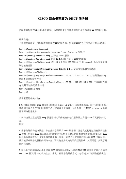
CISCO路由器配置为DHCP服务器把路由器配置为dhcp的服务器端,以对路由器下所连接的客户工作站进行ip地址的分配。
解决实例;下面的配置命令,可以配置路由器为DHCP服务器,用以给DHCP客户端动态分配ip地址。
Router1#configure terminalEnter configuration commands, one per line. End with CNTL/Z.Router1(config)#service dhcp //开启 DHCP 服务Router1(config)#ip dhcp pool 172.25.1.0/24 //定义DHCP地址池Router1(dhcp-config)#network 172.25.1.0 255.255.255.0 // 用network 命令来定义网络地址的范围Router1(dhcp-config)#default-router 172.25.1.1 //定义要分配的网关地址Router1(dhcp-config)#exitRouter1(config)#ip dhcp excluded-address 172.25.1.1 172.25.1.50 //该范围内的ip 地址不能分配给客户端Router1(config)#ip dhcp excluded-address 172.25.1.200 172.25.1.255 //该范围内的ip地址不能分配给客户端Router1(config)#endRouter1#关于配置的相关讨论;1 CISCO路由器的dhcp服务器功能也是在ios 12.0(1)T.以后才出现的,这一功能的出现,使我们没有必要在专门网络的中心(或者说企业本部)另外配置一台DHCP server,从而降低了网络构建成本。
2 在路由器上直接配置dhcp服务器相比于传统的在专门服务器上实现dhcp有其独到的优点。
比如A 由于传统的构建方法是,在企业的总部设立DHCP服务器,各分支机构通过路有器去获取ip地址,所以当dhcp服务器出现问题的时候,整个企业的网络都会受到影响,而如果把dhcp 服务器功能设在各个分支机构的路由器上实现,则某个分支机构的路由器DHCP出现问题,就只能影响该分支机构的网络本身,而其他分支机构则不受任何影响。
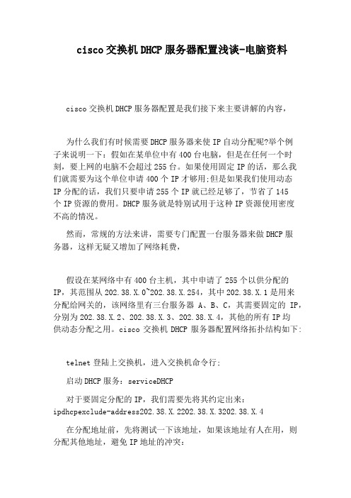
cisco交换机DHCP服务器配置浅谈-电脑资料cisco交换机DHCP服务器配置是我们接下来主要讲解的内容,为什么我们有时候需要DHCP服务器来使IP自动分配呢?举个例子来说明一下:假如在某单位中有400台电脑,但是在任何一个时刻,要上网的电脑不会超过255台。
如果使用固定IP的话,那么我们就需要为这个单位申请400个IP才够用;但是如果我们使用动态IP分配的话,我们只要申请255个IP就已经足够了,节省了145个IP资源的费用。
DHCP服务就是特别试用于这种IP资源使用密度不高的情况。
然而,常规的方法来讲,需要专门配置一台服务器来做DHCP服务器,这样无疑又增加了网络耗费,假设在某网络中有400台主机,其中申请了255个以供分配的IP,其范围从202.38.X.0~202.38.X.254,其中202.38.X.1是用来分配给网关的,该网络里有三台服务器A、B、C,其需要固定的IP,分别为202.38.X.2、202.38.X.3、202.38.X.4,其他的所有IP均供动态分配之用。
cisco交换机DHCP服务器配置网络拓扑结构如下:telnet登陆上交换机,进入交换机命令行;启动DHCP服务:serviceDHCP对于要固定分配的IP,我们需要先将其约定出来:ipdhcpexclude-address202.38.X.2202.38.X.3202.38.X.4在分配地址前,先将测试一下该地址,如果该地址有人在用,则分配其他地址,避免IP地址的冲突:ipdhcppingpackets3设置DHCP地址池全局变量:ipdhcppool1设置动态分配的IP地址范围、子网掩码:network202.38.X.0255.255.255.0//动态分配IP范围,这里给定的是202.38.X.0到255.255.255.0,也就是该段所有IP设置网关:default-router202.38.X.1设置DNS服务器地址:dns-server202.38.193.33202.112.17.33就这么简单,一个cisco交换机DHCP服务器配置完成了。

采用CISCO packer 7.1 完成DHCP服务器的配置Packet Tracer 7.1模拟器上配置DHCP(动态主机配置协议) 服务器一、实验目的:掌握在Packet Tracer 模拟器上配置DHCP(动态主机配置协议)服务器的技能,深入理解DHCP服务的工作过程。
二、实验环境该实验是在Packet Tracer 模拟器中进行的,设备如下: 1、 Packer Tracer7.1.0模拟器软件安装包一个;三、实验内容 101、分别配置物理系和化学系各一台DHCP服务器;为两个局域网规划ip地址2、对两个局域网分别测试是否可以从各自的DHCP服务器获得正常IP地址。
四、实验步骤 801、安装Packet Tracer 7.1.0模拟器软件在Packet Tracer 7.1软件安装包中选择PacketTracer7.1_setup.exe双击,进入软件安装向导。
按照软件安装向导进行安装。
安装完成后打开PacketTracer窗口页面,如图1所示。
图1 Packet Tracer主页面2、搭建网络环境使用Packet Tracer模拟器根据如下网络拓扑结构如图2所示,搭建网络。
路由器选用2811,需在1槽扩容一块NM-4E。
扩容步骤:先关电-扩容NM-4E-开机。
扩容前扩容后图2 网络拓扑图3、配置R1路由器静态路由:4、启用R1路由器DHCP中继代理:Router01(config)#int fa 0/0 /登陆化学系局域网的网关接口Router01 (config-if)#ip helper-address 192.168.1.4 /启用配置DHCP 中继代理。
DHCP 服务器是192.168.1.4 Router01 (config-if)#int fa 0/1 /登陆物理系局域网的网关接口Router01 (config-if)#ip helper-address 192.168.1.2 /启用配置DHCP 中继代理。
Cisco路由器做DHCP和DNS服务器Cisco路由器作为网络设备的重要组成部分,除了实现数据转发和路由功能外,还可以承担DHCP(动态主机配置协议)和DNS(域名系统)服务器的角色。
本文将介绍如何在Cisco路由器上配置DHCP和DNS服务器,并详细解释其原理和作用。
一、概述在计算机网络中,DHCP和DNS是两个非常重要的网络协议。
DHCP协议用于自动分配IP地址给连接到网络的设备,而DNS协议则负责将域名解析为IP地址,以实现设备之间的通信。
二、Cisco路由器配置DHCP服务器1. 进入路由器的全局配置模式:```enableconfigure terminal```2. 创建一个IP地址池,指定可分配的IP地址范围、默认网关和DNS服务器:```ip dhcp pool POOL_NAMEnetwork NETWORK_ADDRESS SUBNET_MASKdefault-router DEFAULT_GATEWAYdns-server DNS_SERVER```其中,POOL_NAME为IP地址池的名称;NETWORK_ADDRESS 为网络地址;SUBNET_MASK为子网掩码;DEFAULT_GATEWAY为默认网关的IP地址;DNS_SERVER为DNS服务器的IP地址。
3. 指定DHCP租约的有效期:```lease DAY HOURS MINUTES```其中,DAY为天数,HOURS为小时数,MINUTES为分钟数。
4. 退出DHCP配置模式:```exit```5. 启用DHCP服务器:```service dhcp```三、Cisco路由器配置DNS服务器1. 进入路由器的全局配置模式:```enableconfigure terminal```2. 创建一个静态DNS解析:```ip host DOMAIN_NAME IP_ADDRESS```其中,DOMAIN_NAME为域名,IP_ADDRESS为对应的IP地址。
Cisco交换机配置DHCP方案The solution:One, if you don't use the DHCP function of the switch, you use the PC's DHCP functionality!Configure the DHCP server on the switch:IP DHCP - server 192.168.0.69Set the same IP address for the same DHCP server for each VLAN in the switch:Interface VlanllIP address 192. 168. 1. 255. 255. 255. 0IP helper - address 192.168.0.69 DHCP Server IPInterface Vlanl2IP address 192. 168. 2. 255. 255. 255. 0IP helper - address 192.168.0.69 DHCP Server IPSet the network address on the DHCP server for 192・ 168・ 1.0, 192. 168.2. 0, and z,road/z to these scopesThe selector option is set to the interface IP address corresponding to the VLAN・Using the DIICP functionality of the three-layer switch, the IP address of multiple vlans is automatically allocated(1) configuration method 1Assign addresses to multiple vlansThere are partial addresses in VLAN that are manually allocatedSpecify gateways, Wins servers, etcVLAN 2 has a valid period of 1 day, and the other 3 daysAssign the specified IP address to a specific user by the MAC addressThe final configuration is as follows:IP DHCP deal-address 10.1.1.1 10.1.19 / / the address that is not used for dynamic address allocationIP DHCP excluded - address 10.1.1.2410.1.254IP DHCP deal-address 10. 1. 2. 1 10. 1. 2. 19i■IP DHCP pool global / / global is pool name, specified by the user Network 10.1.0.0 255.0.0 / / dynamically allocated addresssegmentsDomain-name die nt. com / / configure the doma in suffix for the clientDNS - server 10. 1. 1. 1 10. 1. 1. 2 / / configure the DNS server for the clientNetbios 一name-server 10.1.1.5 10.1.1.1.6 / / the wins server for the clientNetbios - node-type h-node / / for the client configuration node pattern (which affects the success of the name interpretation, such as h-node 二first through the wins service)To explain.・・)Lease 3 / / address lease term: 3 daysIP DHCP pool vlanlNetwork 10. 1. 1. 0 255・ 255・ 255・ 0 / / this pool is the child pool of global, inheriting domain-name from global poolThe optionDefault-router 10.1.1.101.101 / / configure the default gateway for the clientIP DHCP pool vian2 / / pool for another VLAN configurationNetwork 10. 1. 2. 0 255. 255. 255. 0Default 一router 10. 1. 2. 100 10. 1. 2. 101Lease 1IIP DHCP pool vlanl_john / / always for MAC addresses・・・ Machine assignment・・・ addressHost 10. 1. 1.21 255. 255. 255. 0Client-identifier 010050. Unlisted. 6384 / / client -identifier 二01 plus the client network card addressi■IP DHCP pool vlanl_tomHost 10. 1. 1. 50 255. 255. 255. 0Client - identifier abl 010010.3. Eac8Related DHCP debug commands:No service DHCP / / stop DHCP service [default to enable DHCPserviceSh IP DIICP binding / / display address allocationShow IP DHCP conflict / / display address conflictDebug IP DHCP server {events |, | linkage) / / observe DHCP server working conditionsIf the DHCP client does not assign IP addresses, there are two common reasons・The first is that there is no port set for the connection clientPortfast way. The MS client checks the network card after it's turned on, and the Link is UP, and starts sending DHCPDISCOVER requestThe switch port is going through the generation tree calculation, which typically takes 30 to 50 seconds to get to the forwarding state・The MS client has not received DHCP SERVERThe response will set a 169・ 169. X. X IP address to the network card. The solution is to set the switch port to the Portfast mode:CatOS (4000/5000/6000) : set spantree portfast mod_num/port_num enable; IOS (2900/3500):Interface・・・;Spanning 一tree portfast (2) configuration method 2A 3550EMI switch, which divides three vlansVlan2 is the server s network, named server, IP address segment 192. 168.2. 0, subnet mask: 255. 255. 255. 0, netClose: 192.168.2.1, the domain server is the Windows 2000 advance server, and also the DNS server, with an IP address of 192. 16& 2. 10Vlan3 is the network of client 1, the IP address segment is 192. 168. 3. 0, subnet mask: 255. 255. 255. 0, gateway: 192. 168. 3. 1workO1Vlan4 is the network of client 2, named work02, IP address segment 192.168.4.0, subnet mask: 255.255.255・0, netGuan: 192. 168. 4. 1,3550 DHCP servers, ports 1-8 to VLAN 2, port 9-16 to VLAN 3, port 17-24 to VLAN 4.DHCP server implementation function:Each VLAN retains a 2-10 IP address regardless of configuration, for example, 192. 168. 2. 0, with an IP address of 192. 168. 2. 2 to 192. 16& 2. 10Not assigned.Safety requirements:VLAN 3 and VLAN 4 are not allowed to access each other, but bothcan access the server's VLAN 2,The default access control list rule is to reject all packages・The configuration commands and steps are as follows:Step 1: create VLAN:The Switch > enSwitch# Vian DatabaseStep 2: set the VLAN IP address:Switch# Config TThe Switch (Config) > Int Vian 2Switch (config-vlan) Ip Address 192.168.2.255.255.255.0 The Switch (Config - vlan) No ShutSwitch (config-vlan) > Int vlan 3/ * note: since there is no port allocation to VLAN2, 3, 4, the VLAN will DOWN, and then the port will be assigned to vlans, VLAN w订1 up * /Step 3: set the port global parametersSwitch (Config) Interface Range is 0/1-24Switch (config-if -range) Switchport Mode AccessSwitch (config-if -range) -tree PortfastStep 4: add the port to VLAN2, 3, 4 / * add port 1-8 to VLAN 2 * /The Switch (Config) Interface Range is 0/1-8Switch (config-if - range) Switchport Access Vian 2/ * add port 9~16 to VLAN 3 * /Switch (Config) Interface Range Fa 0/9-16Switch (config-if - range) Switchport Access Vian 3/ * add port 17-24 to VLAN 4 * /Switch (Config) Interface Range Fa 0/17-24Switch (config-if -range) Switchport Access Vian 4The Switch (Config - if - range) Exit/ * after this step, the VLAN will rise * /Step 5: configure 3550 as the DHCP server/ * VLAN 2 available address pool and the configuration of the corresponding parameter, several vlans will have several address pool * /The Switch (Config) Ip Dhcp Pool TestOl / * sets the distributable subnet * /The Switch (config-pool) Network 192.168.2.0, 255.255.255.0 / * set up the DNS server * /Switch (config-pool) Dns 一server 192・ 168.2.10/ * sets the gateway * / for the subnetSwitch (config-pool) Default - router 192. 16& 2. 1/ * configure the address pool used by VLAN 3 and the corresponding parameter * /The Switch (Config) Ip Dhcp Pool Test02The Switch (config-pool) Network 192.168.3.0 255.255.255.0Switch (config-pool) Dns 一server 192・ 168.2.10Switch (config-pool) Default 一router 192.168.3.1/ * configure the address pool used by VLAN 4 and the corresponding parameter * /The Switch (Config) Ip Dhcp Pool Test03The Switch (config-pool) Network 192.168.4.0 255.255.0Switch (config-pool) Dns 一server 192・ 168.2.10Switch (config-pool) Default 一router 192・ 168.4.1Step 6: set DHCP to keep the unallocated addressSwitch (Config) Ip Dhcp deal-address 192.168.2.2 192.168.2.10Switch (Config) Ip Dhcp deal-address 192. 168. 3.2 192. 168.3.10Switch (Config) Ip Dhcp deal-address 192. 168. 4. 2 192. 168.4.10 Step 7:enable routingThe VLAN hosts can access each other when the / * is enabledThe Switch Ip Routing (Config)Step 8: configure access control listsSwitch (Config) access-list 103 permit IP 192.16& 2.0 0.0.255192. 168. 3. 0 0. 0. 255Switch (Config) access-list 103 permit IP 192.16& 3.0 0.0.255192. 168. 2. 0 0. 0. 255Switch (Config) access-list 103 permit udp any eq bootpc Switch (Config) access-list 103 permit udp any eq TFTP Switch (Config) access-list 103 permit udp any eq bootpc any Switch (Config) access-list 103 permit udp any eq TFTP anySwitch (Config) access-list 104 permit IP 192. 168.2.0 0.0.255192. 168. 4. 0 0. 255Switch (Config) access-list 104 permit IP 192.168.4.0.0.255192. 168.2.0 0. 0. 255Switch (Config) access-list 104 permit udp any eq TFTP anySwitch (Config) access-list 104 permit udp any eq bootpc any Switch (Config) access-list 104 permit udp any eq bootpc anySwitch (Config) access-list 104 permit udp any eq TFTP anyStep 9: apply access control lists/ * to apply the access control list to VLAN 3 and VLAN 4, VLAN 2 does not need * /The Switch (Config) Int Vian 3Switch (config-vlan) IP access -group 103 outThe Switch (Config - vlan) Int vlan 4Switch (config-vlan) IP access-group 104 outStep 10: finish and save the configurationThe Switch (Config 一vlan) EndSwitch# the Copy Run Start。
CISCO路由器上配置DHCP服务一:如图二:说明使用dynamips,ip地址配置如上。
R7做为DHCP服务器,负责给PC1和PC2配置ip。
修改dynamips的R6和R7使其可以分别与真实是PC1和vmware虚拟PC2相连。
三:配置在R7上:Router>enableRouter#conf tRouter(config)#host R7R7(config)#no ip domain-lookupR7(config)#inter fa2/0R7(config-if)#ip add 10.1.1.1 255.255.255.0R7(config-if)#no shutR7(config-if)#inter s1/4R7(config-if)#ip add 2.1.1.2 255.255.255.0R7(config-if)#no shutR7(config-if)#exitR7(config)#router ripR7(config-router)#network 10.0.0.0R7(config-router)#network 2.0.0.0R7(config-router)#exitR7(config)#ip dhcp pool ippc2 /配置dhcp地址池名ippc2R7(dhcp-config)#network 10.1.1.0 255.255.255.0 /配置地址池范围R7(dhcp-config)#default-router 10.1.1.1 /配置分配网关地址R7(dhcp-config)#dns-server 111.111.111.111 222.222.222.222 /配置分配的dns服务器地址R7(dhcp-config)#exitR7(config)#ip dhcp excluded-address 10.1.1.1 10.1.1.10 /排除地址池中ip地址R7(config)#ip dhcp pool ippc1R7(dhcp-config)#network 192.168.1.0 255.255.255.0R7(dhcp-config)#default-router 192.168.1.1R7(dhcp-config)#dns-server 111.111.111.111 222.222.222.222R7(dhcp-config)#exitR7(config)#ip dhcp excluded-address 192.168.1.1 192.168.1.20R7(config)#在R5上:Router>enRouter#conf tRouter(config)#host R5R5(config)#no ip domain-lookupR5(config)#inter s1/2R5(config-if)#ip add 2.1.1.1 255.255.255.0R5(config-if)#no shutR5(config-if)#inter s1/1R5(config-if)#ip add 1.1.1.2 255.255.255.0R5(config-if)#no shutR5(config-if)#exitR5(config)#router ripR5(config-router)#net 1.0.0.0R5(config-router)#net 2.0.0.0R5(config-router)#endR5#在R6上:Router>enRouter#conf tRouter(config)#no ip domain-lookupRouter(config)#hostname R6R6(config)#inter s1/0R6(config-if)#ip add 1.1.1.1 255.255.255.0R6(config-if)#no shutR6(config-if)#interface fa2/0R6(config-if)#ip add 192.168.1.1 255.255.255.0R6(config-if)#ip helper-address 2.1.1.2 /配置为dhpc中继,指向dhcp服务器地址R6(config-if)#no shutR6(config-if)#exitR6(config)#router ripR6(config-router)#network 1.0.0.0R6(config-router)#network 192.168.1.0R6(config-router)#endR6#四:实验结果在pc1上:、在pc2上:在R7上:R7#show ip dhcp binding/查看分配的地址Bindings from all pools not associated with VRF:IP address Client-ID/ Lease expiration TypeHardware address/User name10.1.1.11 0100.0c29.0fc4.f6 Oct 30 2007 11:48 PM Automatic192.168.1.21 0100.030d.44c2.c7 Oct 31 2007 12:14 AM AutomaticR7#show ip dhcp pool /查看dhcp地址池Pool ippc2 :Utilization mark (high/low) : 100 / 0Subnet size (first/next) : 0 / 0Total addresses : 254Leased addresses : 1Pending event : none1 subnet is currently in the pool :Current index IP address range Leased addresses10.1.1.12 10.1.1.1 - 10.1.1.254 1Pool ippc1 :Utilization mark (high/low) : 100 / 0Subnet size (first/next) : 0 / 0Total addresses : 254Leased addresses : 1Pending event : none1 subnet is currently in the pool :Current index IP address range Leased addresses192.168.1.22 192.168.1.1 - 192.168.1.254 1R7#五:说明1:问在R7上配置有两个地址池,在分配地址时会分配混吗?答:不会,因为路由器R7会根据数据包的源地址或接口地址来区分相应的地址池2:问R6(config-if)#ip helper-address 2.1.1.2含义?答:这个命令是配置R6为dhcp relay(dhcp 中继),当R6的fa2/0接口收到pc1发出的dhcp discover请求广播包后,路由器默认是不能转发广播的,于是通过这个命令,R6把请求的广播包转换为发向R7的单播包来完成请求。
CISCO三层交换机怎么配置DHCP服务?
利⽤CISCO三层交换机⾃带的DHCP功能,可以实现多VLAN的IP地址⾃动分配,在三层交换机上如何配置DHCP服务呢,下⾯由⼩编介绍下具体操作吧,
1、⾸先将三层交换机开机,电脑telnet 远程连接,并进⼊全局模式下,如图所⽰:
2、在全局模式下开启DHCP服务,输⼊“service dhcp”,然后按回车,如图所⽰:
3、指定不通过DHCP 地址池中分配的地址,也就是排除的地址。
这⾥排除192.168.1.1到192.168.1.10的地址,输⼊“ip dhcp excluded-address 192.168.1.1 192.168.1.10"如图所⽰:
4、配置⼀个名为“cs”的地址池,输⼊”ip dhcp pool cs",如图所⽰:
5、指定要通过DHCP分配的⽹段和掩码,输⼊”network 192.168.1.0 255.255.255.0",如图所⽰:
6、为客户机配置DNS服务器,输⼊“dns-server 218.2.135.1",如图所⽰:
7、设置地址租⽤期为”3“,输⼊”lease 3",租期可以根据实际情况做调整,如图所⽰:
8、为客户机配置⽹关为“192.168.1.1”,输⼊“default-router 192.168.1.1”,如图所⽰:
9、这样就设置完成了,只要是属于192.168.1.0/24⽹段的客户机就可以⾃动获取IP地址了。
这⾥注意了,如果存在多个VLAN,每个VLAN都需要设置DHCP服务。
Packet Tracer 7.1模拟器上配置DHCP(动态主机配置协议) 服务器
一、实验目的:
掌握在Packet Tracer 模拟器上配置DHCP(动态主机配置协议)服务器的技能,深入理解DHCP服务的工作过程。
二、实验环境
该实验是在Packet Tracer 模拟器中进行的,设备如下:
1、Packer Tracer 7.1.0模拟器软件安装包一个;
三、实验内容10
1、分别配置物理系和化学系各一台DHCP服务器;为两个局域网规划ip地址
2、对两个局域网分别测试是否可以从各自的DHCP服务器获得正常IP地址。
四、实验步骤80
1、安装Packet Tracer 7.1.0模拟器软件
在Packet Tracer 7.1软件安装包中选择PacketTracer7.1_setup.exe双击,进入软件安装向导。
按照软件安装向导进行安装。
安装完成后打开PacketTracer窗口页面,如图1所示。
图1 Packet Tracer主页面
2、搭建网络环境
使用Packet Tracer模拟器根据如下网络拓扑结构如图2所示,搭建网络。
路由器选用2811,需在1槽扩容一块NM-4E。
扩容步骤:先关电-扩容NM-4E-开机。
扩容前
扩容后
图2 网络拓扑图3、配置R1路由器静态路由:
4、启用R1路由器DHCP中继代理:
Router01(config)#int fa 0/0 /登陆化学系局域网的网关接口
Router01 (config-if)#ip helper-address 192.168.1.4 /启用配置DHCP 中继代理。
DHCP 服务器是192.168.1.4
Router01 (config-if)#int fa 0/1 /登陆物理系局域网的网关接口
Router01 (config-if)#ip helper-address 192.168.1.2 /启用配置DHCP 中继代理。
DHCP 服务器是192.168.1.2
5、配置R2路由器静态路由:
6、配置Wulixi DHCP服务器
点击拓扑图中的DHCP服务器,打开服务器配置页面,如图3所示,在左侧配置栏中选择DHCP,则显示DHCP配置页面。
在Service栏选择“on”,打开服务;
Default Gateway: 192.168.1.254和DNS 可以默认;
Wulixi:Serverpool配置(DHCP IP地址池):
默认网关:192.168.3.254
默认DNS: 192.168.1.100
Start IP Address中输入中的开始地址,192.168.3.1-253;Maximum number of users 中输入可以分配的最大地址数个数,可以自己确定这个数目,最大值为253个。
7、配置huaxue DHCP服务器
点击拓扑图中的DHCP服务器,打开服务器配置页面,如图3所示,在左侧配置栏中选择DHCP,则显示DHCP配置页面。
在Service栏选择“on”,打开服务;
Default Gateway: 192.168.1.254和DNS 可以默认;
huaxue: Serverpool配置(DHCP IP地址池):
默认网关:192.168.4.254
默认DNS: 192.168.1.100
Start IP Address中输入中的开始地址,192.168.4.1-253;Maximum number of users中输入可以分配的最大地址数个数,可以自己确定这个数目,最大值为253个。
图3 DHCP服务器配置页面
4、配置主机
在该局域网中的主机目前有A、B、C、D、E五台,分别打开物理系和化学系的主机,在配置Config栏,在IP Configuration中选择DHCP(自动获取),稍等会发现IP Address自动获取了IP地址和子网掩码。
如图4所示。
图4 自动获取网络配置
查看各pc客户端是否可以自动获取本系的IP网络配置。
并记录各PC获得的IP地址。
保留实验截图,提交实验报告。