EZ USB ControlPanel控制面板使用及USB相关问题
- 格式:pdf
- 大小:1.57 MB
- 文档页数:11
问:我测试你们的程序的时候,go main 进不去主函数,进入的是一段汇编。
是怎么回事?答:程序如果要进行设断点,观察变量等操作,要先调入project文件,然后再调入out文件。
如果是可以直接执行能看到结果的,就直接调入out文件,run就可以。
问:CY68013的固件程序怎么修改?答:在把QQ2812都研究清楚了,有精力有兴趣自己可以买一本EZ-USB的书好好看看。
在此之前,请不要随便更改固件代码,因为一旦出错,可能带来不必要的麻烦。
固件代码是通过USBControlPanel,使用USB接口进行下载的。
:2812的主频是最大150M,我如果想设为100M是在那里设置?答:打开工程,在Source文件夹下,打开DSP28_SysCtro.c文件,找到如下语句,修改即可。
// Initalize PLLSysCtrlRegs.PLLCR = 0x02;///锁相环产生的时钟频率定标,这里配置为30M问:为什么我的程序在SRAM中正常,烧入Flash后不对?答:1、请先确认你编译的时候使用了flash.cmd,推荐使用我们提供的flash.cmd,如果自己更改了这个文件,请先确认cmd文件的正确性;2、编译的时候,如果选择release模式,请检查一下build option,把其中的opt level改为none,即取消编译优化选项,很多语句在优化的时候可能会产生错误的优化结果。
或者选择debug模式编译,烧写正确后再改为release模式,通过对比两种模式的编译选项也能看出其中的区别。
3、程序在flash中运行会比在ram中运行大概慢20%,因此对于一些时序敏感的外设,比如usb总线,就有可能需要调整时序,否则就会有问题。
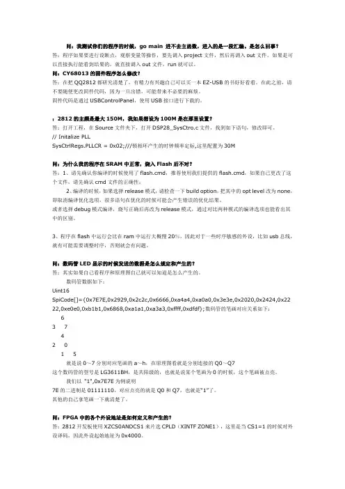
问:数码管LED显示的时候发送的数据是怎么规定和产生的?答:其实如果自己看程序和原理图自己就可以知道是怎么产生的。
数码管数据如下:Uint16SpiCode[]={0x7E7E,0x2929,0x2c2c,0x6666,0xa4a4,0xa0a0,0x3e3e,0x2020,0x2424,0x22 22,0xe0e0,0xb1b1,0x6868,0xa1a1,0xa3a3,0xffff,0xdfdf};数码管的笔画对应关系如下:63 742 01 5就是说0~7分别对应笔画的a~h,在原理图看就是分别连接的Q0~Q7这个数码管的型号是LG3611BH,是共阳级的,也就是说某个笔画为0的时候,这个笔画被点亮。
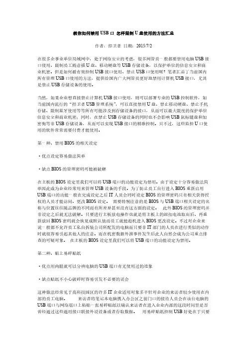
教你如何禁用USB口怎样限制U盘使用的方法汇总作者:捍卫者日期:2015/7/2在很多企事业单位局域网中,处于网络安全的考虑,很多网管员一般都要禁用电脑USB接口使用、限制员工随意插U盘、移动硬盘等USB存储设备,以保护单位的信息安全和商业机密。
但是如何最有效控制USB接口使用、禁止USB口使用呢?笔者汇总了当前国内所有管理USB口使用的方法,提供给国内广大网管员更好地禁用计算机USB接口,尤其是禁止USB存储设备的使用。
当然,如果企业想直接禁止计算机USB接口使用,则可以部署专业的USB控制软件,如当前国内流行的“捍卫者USB管理系统”,可以直接禁用U盘、禁止移动硬盘、禁止手机存储、限制蓝牙使用等等所有可能涉及到存储设备的接口,从而可以最大限度的保护单位信息安全和商业机密;同时,在禁止USB存储设备的同时也不会影响USB鼠标键盘和加密狗等非USB存储设备,从而可以实现USB接口的精准控制。
只不过,这些监控U口使用的软件常常需要付费才能使用。
第一种、禁用BIOS的相关设定·优点设定容易做法简单·缺点BIOS的管理密码可能被破解在主板的BIOS设定里我们可以将USB端口的功能设定为禁用。
由于设定十分容易做法简单因此成为企业经常用来管理USB设备的手段。
为了防止员工自行进入BIOS重新启用USB端口的功能一般在完成设定之后IT人员会同时设定BIOS的管理密码只有相关获得授权的人员才能访问、更改BIOS设定。
需要特别注意的是BIOS与USB端口相关设定的名称与位置往往随品牌的不同而有所差异甚至没有这方面的设定。
此外BIOS的管理密码并非设定之后就无法破解。
只要进行主板放电操作也就是将主板上的纽扣电池取出后、再重新放回BIOS密码就会恢复成默认值而员工就能趁机进入BIOS更改设定。
不过对企业来说一般都不允许员工私自拆装公司所配发的电脑而只要非IT部门的人员在进行类似的动作时就很容易引起其他人的注意。
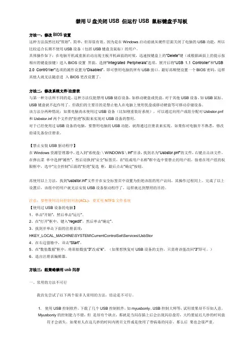
禁用U盘关闭USB 但运行USB 鼠标键盘手写板方法一:修改BIOS设置这种方法虽然比较“原始”、简单,但却很有效。
因为是在Windows启动前就从硬件层面关闭了电脑的USB功能,所以比较适合长期不使用USB设备(包括USB键盘及鼠标)的用户。
具体操作如下:在电脑开机或重新启动出现主板开机画面的时候,迅速按键盘上的“Delete”键(或根据画面上的提示按相应的键盘按键)进入BIOS设置界面,选择“Integrated Peripherals”选项,展开后将“USB 1.1 Controller”和“USB 2.0 Contr01ler”选项的属性设置为“Disabled”,即可禁用电脑的所有USB接口。
最好再顺便设置一个BIOS密码,这样其他人就无法随意进入BIOS更改设置了。
方法二:修改系统文件/注册表与第一种方法所不同的是,这种方法仅能禁用USB储存设备,如移动硬盘或优盘,对于其他USB设备,如USB鼠标、USB键盘就不起作用了。
但我们的主要目的是禁止他人在电脑上使用优盘或移动硬盘等可移动存储设备。
该方法分两种情况:如果电脑尚未使用过USB设备(比如刚重装好系统),可以通过向用户或组分配对Usbstor.pnf 和Usbstor.inf两个文件的“拒绝”权限来实现对USB设备的禁用。
对于已经使用过USB设备的电脑,要禁用电脑的USB功能,就得通过注册表来实现。
如果你对电脑并不熟悉,修改前请先备份注册表。
【禁止安装USB驱动程序】在Windows资源管理器中,进入到“系统盘:\WINDOWS\inf”目录,找到名为“Usbstor.pnf”的文件,右键点击该文件,在弹出菜单中选择“属性”,然后切换到“安全”标签页,在“组或用户名称”框中选中要禁止的用户组,接着在用户组的权限框中,选中“完全控制”后面的“拒绝”复选框,最后点击“确定”按钮。
再使用以上方法,找到“usbstor.inf”文件并在安全标签页中设置为拒绝该组的用户访问,其操作过程同上。

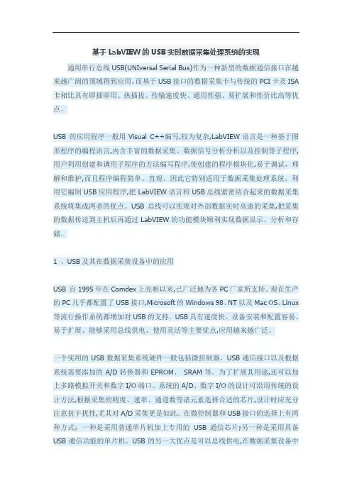
基于LabVIEW的USB实时数据采集处理系统的实现通用串行总线USB(UNIversal Serial Bus)作为一种新型的数据通信接口在越来越广阔的领域得到应用。
而基于USB接口的数据采集卡与传统的PCI卡及ISA 卡相比具有即插即用、热插拔、传输速度快、通用性强、易扩展和性价比高等优点。
USB 的应用程序一般用Visual C++编写,较为复杂,LabVIEW语言是一种基于图形程序的编程语言,内含丰富的数据采集、数据信号分析分析以及控制等子程序,用户利用创建和调用子程序的方法编写程序,使创建的程序模块化,易于调试、理解和维护,而且程序编程简单、直观。
因此它特别适用于数据采集处理系统。
利用它编制USB应用程序,把LabVIEW语言和USB总线紧密结合起来的数据采集系统将集成两者的优点。
USB总线可以实现对外部数据实时高速的采集,把采集的数据传送到主机后再通过LabVIEW的功能模块顺利实现数据显示、分析和存储。
1 、USB及其在数据采集设备中的应用USB 自1995年在Comdex上亮相以来,已广泛地为各PC厂家所支持。
现在生产的PC几乎都配置了USB接口,Microsoft的Windows 98、NT以及Mac OS、Linux 等流行操作系统都增加对USB的支持。
USB具有速度快、设备安装和配置容易、易于扩展、能够采用总线供电、使用灵活等主要优点,应用越来越广泛。
一个实用的USB数据采集系统硬件一般包括微控制器、USB通信接口以及根据系统需要添加的A/D转换器和EPROM、SRAM等。
为了扩展其用途,还可以加上多路模拟开关和数字I/O端口。
系统的A/D、数字I/O的设计可沿用传统的设计方法,根据采集的精度、速率、通道数等诸元素选择合适的芯片,设计时应充分注意抗干扰性,尤其对A/D采集更是如此。
在微控制器和USB接口的选择上有两种方式:一种是采用普通单片机加上专用的USB通信芯片;另一种是采用具备USB通信功能的单片机。
用屏蔽usb接口软件教你如何禁用usb接口、实现Win7禁用USB接口现在由于大家上班都是用电脑,这样工作中积累的一些客户资料、工作成果等等都存储在单位的电脑上,同时这些文件常常涉及到单位的商业秘密信息,是重要的无形资产,为此必须加以保护。
同时,现在U盘的使用极为普遍,存储空间越来越大,存储速度也越来越快,这使得员工可以轻松将公司电脑的大量文件复制到U盘里面携带出去,从而实现了某种个人目的。
因此,必须采取有效的举措来禁止公司电脑随意插U盘的行为,禁止复制电脑文件到U盘的行为,甚至需要禁止电脑USB接口的使用,从而完全禁止USB存储设备,保护企业电脑文件安全和商业机密。
那么,具体如何限制U盘使用、屏蔽USB接口的使用呢?笔者以为,可以通过以下途径来禁用USB存储设备,从而阻止U盘使用、限制USB存储设备的使用。
具体方法如下: 1.通过设备管理器来禁用U盘、禁用USB存储设备。
右键点击我的电脑-->管理,然后选择设备管理器-->通用串行总线控制器-->有两个u sb root hub 禁用这两个项目里面:常规-->设备方法-->停用 2.在BIOS种禁用USB接口、屏蔽U口使用。
进入BIOS设置,选择“Integrated Peripherals”选项,展开后将“USB1.1Controll er”和“USB2.0Contr01ler”选项的属性设置为“Disableed”,即可禁用USB接口。
最后别忘记给BIOS设置上一个密码,这样他人就无法通过修改注册表解“锁”上述设备了。
注意:这个方法是完全禁止了USB接口,也就是说各种USB接口的设备均不能用了,当然也包括了U盘和移动盘。
3.禁止安装USB驱动程序、限制USB驱动安装 在Windows资源管理器中,进入到“系统盘:WINDOWSinf”目录,找到名为“Usbstor. pnf”的文件,右键点击该文件,在弹出菜单中选择“属性”,然后切换到“安全”标签页,在“组或用户名称”框中选中要禁止的用户组,接着在用户组的权限框中,选中“完全控制”后面的“拒绝”复选框,最后点击“确定”按钮 4. 注册表禁用USB设备、组策略禁用U盘、注册表禁用USB端口 打开注册表编辑器,依次展开如下分支[HKEY_LOCAL_MACHINE\SYSTEM\CurrentCntrolSet\Services\USBSTOR],在右侧的窗格中找到名为“Start”的DWORD值,双击,在弹出的编辑对话框中将其数值数据修改为十六位进制数值“4”。
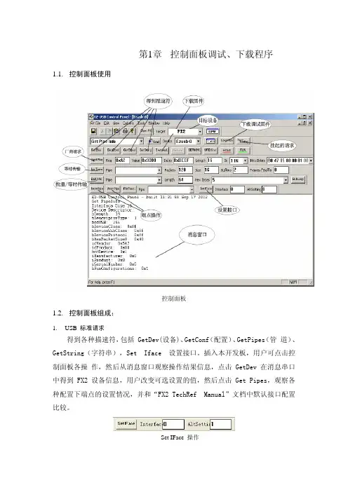
第1章 控制面板调试、下载程序1.1.控制面板使用控制面板1.2.控制面板组成:B 标准请求得到各种描速符,包括 GetDev(设备)、GetConf(配置)、GetPipes(管 道)、GetString(字符串),Set Iface 设置接口。
插入本开发板,用户可点击控制面板各操 作,然后从消息窗口观察操作结果信息,点击 GetDev 在消息串口中得到 FX2 设备信息,用户改变可选设置的值,然后点击 Get Pipes,观察各种配置下端点的设置情况,并和“FX2 TechRef Manual”文档中默认接口配置比较。
操作SetIFace说明:开发板插入 USB2.0 主控器后,提示“高速 USB 设备插入非高速集线器”,默认响应为USB1.1 设备,所以 Get Pipes 得到也是 USB1.1 的端点描速符,需要在固件设置正确后才显示为 USB2.0 设备。
2.Download 固件下载。
因为EZUSB 没有ROM,所以每次上电都必须要下载固件,点击Download,选择一个HEX 文件进行下载,按钮Re-load 是再次下载Download 指定的HEX 3.LoadMon 在线仿真监视程序下载。
仿真监视程序位于C:\Cypress\USB\Target\Monitor目录下,共有五个监视程序,见下表。
监视程序监视程序串口地址范围适用器件mon-ext-sio1-e0.hex 10xe000-0xef75EZUSB,FXmon-ext-sio1-c0.hex10xc000-0xcf75FX2mon-int-sio1.hex10x0000-0x1075EZUSB,FX,FX2mon-ext-sio0-c0.hex00xc000-0xcf75EZUSB,FX,FX2mon-int-sio0.hex00x0000-0x1075ZUSB,FX,FX2安装时,默认使用的是串口1实现在线仿真,如果要使用串口0,请参考Monitor 目录下 readme 文档。


USB 数据传输系统USB 接口是一种总线接口标准,以其高速、稳定、易于扩展、兼容性强和即插即用等特点,赢得了市场认可并得到普及,已经广泛应用于数据传输、图像采集等领域。
为解决实验室所开发的动态测试系统与计算机的数据通信问题,提出并设计了USB2.0数据传输接口,并在硬件和软件方面给予了优化和改进,很大程度地提高了USB 数据实时传输的速度,而且已经成功应用于无线实时数据传输系统和红外数据传输系统中,完全实现了系统设计的预期目标和功能。
一、数据传输系统工作原理我们已在“200帧/秒连续图像分频采集系统”中,利用Cypress公司的EZ-USB开发板AN2131Q成功地开发出USB接口来传输图像数据,其传输速度达到10Mbps。
若要获得更快的传输速度,可采用USB2.0芯片,它的速度最高可达到480Mbps。
基于USB的特性及优点,目前各个厂家都在为抢占市场积极地开发、生产USB设备。
可以预见,随着USB2.0标准的发布以及USB2.0芯片生产的批量化,USB的应用必将越来越广泛。
“200帧/秒连续图像分频采集系统”需要传输的每幅图像的大小为256×256(数据量为64K)。
由于我们已将EZ-USB开发板的内存扩展为64K双口RAM,而且分为高、低32K 来并行存取数据,所以我们在计算机读取数据时每次读取32K,这样就可以大大提高传输速度。
当计算机发出读取数据命令前,开发板上的单片机不工作;当计算机发出读取数据命令时,开发板上的单片机也同时开始工作,它主要完成将扩展内存的数据传输给SIE,然后数据在SIE中进行处理后经USB电缆传给计算机,最后在计算机中进行实时显示。
二、数据传输系统工作方式新型的通用串行总线USB,具有数据传输速度快、兼容性强、即插即用等优点,已经广泛应用于数据传输、图像采集领域。
可以满足实验室的要求。
本实验室开发的动态存储测试仪器,过去主要采用计算机老式接口进行通信,其数据传输速率相对较低,不能满足大容量存储测试仪器数据传输的要求。
MB166BUSB MonitorUser GuideCopyright © 2022 ASUSTeK COMPUTER INC. All Rights Reserved.No part of this manual, including the products and software described in it, may be reproduced, transmitted, transcribed, stored in a retrieval system, or translated into any language in any form or by any means, except documentation kept by the purchaser for backup purposes, without the express written permission of ASUSTeK COMPUTER INC. (“ASUS”).Product warranty or service will not be extended if: (1) the product is repaired, modified or altered, unless such repair, modification of alteration is authorized in writing by ASUS; or (2) the serial number of the product is defaced or missing.ASUS PROVIDES THIS MANUAL “AS IS” WITHOUT WARRANTY OF ANY KIND, EITHER EXPRESS OR IMPLIED, INCLUDING BUT NOT LIMITED TO THE IMPLIED WARRANTIES OR CONDITIONS OF MERCHANTABILITY OR FITNESS FOR A PARTICULAR PURPOSE. IN NO EVENT SHALL ASUS, ITS DIRECTORS, OFFICERS, EMPLOYEES OR AGENTS BE LIABLE FOR ANY INDIRECT, SPECIAL, INCIDENTAL, OR CONSEQUENTIAL DAMAGES (INCLUDING DAMAGES FOR LOSS OF PROFITS, LOSS OF BUSINESS, LOSS OF USE OR DATA, INTERRUPTION OF BUSINESS AND THE LIKE), EVEN IF ASUS HAS BEEN ADVISED OF THE POSSIBILITY OF SUCH DAMAGES ARISING FROM ANY DEFECT OR ERROR IN THIS MANUAL OR PRODUCT.SPECIFICATIONS AND INFORMATION CONTAINED IN THIS MANUAL ARE FURNISHED FOR INFORMATIONAL USE ONLY, AND ARE SUBJECT TO CHANGE AT ANY TIME WITHOUT NOTICE, AND SHOULD NOT BE CONSTRUED AS A COMMITMENT BY ASUS. ASUS ASSUMES NO RESPONSIBILITY OR LIABILITY FOR ANY ERRORS OR INACCURACIES THAT MAY APPEAR IN THIS MANUAL, INCLUDING THE PRODUCTS AND SOFTWARE DESCRIBED IN IT.Products and corporate names appearing in this manual may or may not be registered trademarks or copyrights of their respective companies, and are used only for identification or explanation and to the owners’ benefit, without intent to infringe.Table of contentsNotices .........................................................................................................iii Safety information .......................................................................................v Care & cleaning ..........................................................................................vii Takeback services (viii)1.1 Welcome! ......................................................................................1-11.2Package contents .........................................................................1-11.3 Monitor introduction ....................................................................1-21.3.1 Front view .......................................................................1-21.3.2 Auto-Rotate .....................................................................1-32.1 Standing Positions .......................................................................2-12.2 Connecting the USB cable ..........................................................2-22.3 DisplayWidget Lite software .......................................................2-33.1 Specifications ...............................................................................3-13.2Troubleshooting (FAQ) ................................................................3-2NoticesFederal Communications Commission StatementThis device complies with Part 15 of the FCC Rules. Operation is subject to the following two conditions:• This device may not cause harmful interference, and• This device must accept any interference received including interference that may cause undesired operation.This equipment has been tested and found to comply with the limits for a Class B digital device, pursuant to Part 15 of the FCC Rules. These limits are designed to provide reasonable protection against harmful interference in a residential installation. This equipment generates, uses and can radiate radio frequency energy and, if not installed and used in accordance with manufacturer’s instructions, may cause harmful interference to radio communications. However, there is no guarantee that interference willnot occur in a particular installation. If this equipment does cause harmful interference to radio or television reception, which can be determined by turning the equipment off and on, the user is encouraged to try to correct the interference by one or more of the following measures:• Reorient or relocate the receiving antenna.• Increase the separation between the equipment and receiver.• Connect the equipment to an outlet on a circuit different from that to which the receiver is connected.• Consult the dealer or an experienced radio/TV technician for help. Canadian Department of Communications StatementThis digital apparatus does not exceed the Class B limits for radionoise emissions from digital apparatus set out in the Radio Interference Regulations of the Canadian Department of Communications.This class B digital apparatus complies with Canadian ICES-003.NOTE: This monitor is ENERGY STAR certified.This product qualifies for ENERGY STAR in the factorydefault setting which can be restored by “Factory Reset”function in the OSD menu. Changing the factorydefault settings or enabling other features may increasepower consumption that could exceed the ENERGY STARspecified limits.Declaration of ConformityThis device complies with the requirements set out in the Council Directive on the Approximation of the Laws of the Member States relating to Electromagnetic Compatibility (2014/30/EU), Low-voltage Directive (2014/35/EU), ErP Directive (2009/125/EC) and RoHS directive (2011/65/EU). This product has been tested and found to comply with the harmonized standards for Information Technology Equipment, these harmonized standards published under Directives of Official Journal of the European Union.WEEE Symbol StatementThis symbol on the product or on its packaging indicates that this product must not be disposed of with your other household waste. Instead, it is your responsibility to dispose of your waste equipment by handing it over to a designated collection point for the recycling of waste electrical and electronic equipment. The separate collection and recycling of your waste equipment at the time of disposal will help to conserve natural resources and ensure that it is recycled in a manner that protects human health and the environment. For more information about where you can drop off your waste equipment for recycling, please contact your local city office, your household waste disposal service or the shop where you purchased the product.Safety information• Before setting up this USB monitor, carefully read all the documentation that came with the package.• To prevent fire or shock hazard, never expose this USB monitor to rain or moisture.• Never try to open this USB monitor cabinet.• Before using this USB monitor, make sure all cables are correctly connected and the power cables are not damaged. If you detect any damage, contact your dealer immediately.• Avoid dust, humidity, and temperature extremes. Do not place this USB monitor in any area where it may become wet. Place this USB monitor on a stable surface.• Never push objects or spill liquid of any kind into the slots on this USB monitor cabinet.• If you encounter technical problems with this USB monitor, contact a qualified service technician or your retailer.• This USB monitor is powered by USB port which complies with LPS and SELV circuit according to IEC60950-1:2005.WARNINGUsage of other than specified head- or earphones can result in hearing loss due to excessive sound pressures.Please confirm the distribution system in building installation shall provide the circuit breaker rated 120/240V, 20A (maximum).If provided with a 3-pin attachment plug on the power cord, plug the cord into a grounded (earthed) 3-pin outlet. Do not disable the power cord grounding pin, for example, by attaching a 2-pin adapter. The grounding pin is an important safety feature.Stability Hazard.The product may fall, causing serious personal injury or death. To prevent injury, this product must be securely attached to the floor/wall in accordance with the installation instructions.A product may fall, causing serious personal injury or death. Many injuries, particularly to children, can be avoided by taking simple precautions such as:ALWAYS use cabinets or stands or installation methods recommended by the manufacturer of the product set.ALWAYS use furniture that can safely support the product.ALWAYS ensure the product is not overhanging the edge of the supporting furniture.ALWAYS educate children about the dangers of climbing on furniture to reach the product or its controls.ALWAYS route cords and cables connected to your product so they cannot be tripped over, pulled or grabbed.NEVER place a product in an unstable location.NEVER place the product on tall furniture (for example, cupboards or bookcases) without anchoring both the furniture and the product to a suitable support.NEVER place the product on cloth or other materials that may be located between the product and supporting furniture.NEVER place items that might tempt children to climb, such as toys and remote controls, on the top of the product or furniture on which the product is placed.If the existing product is going to be retained and relocated, the same considerations as above should be applied.Restriction on Hazardous Substances statement (India) This product complies with the “India E-Waste (Management) Rules, 2016” and prohibits use of Lead, Mercury, Hexavalent Chromium, polybrominated biphenyls(PBBs) and polybrominated diphenyl ethers(PBDEs) in concentration exceeding 0.1% by weight in homogenous materialsand 0.01% by weight in homogenous materials for cadmium, except of exemptions listed in Schedule 2 of the Rule.Care & cleaning• Cleaning. Turn your monitor off and unplug the power cord. Clean the monitor surface with a lint-free, non-abrasive cloth. Stubborn stainsmay be removed with a cloth dampened with mild cleaner.• Avoid using a cleaner containing alcohol or acetone. Use a cleaner intended for use with the LCD. Never spray cleaner directly on thescreen, as it may drip inside the monitor and cause an electric shock. The following symptoms are normal with the monitor:• You may find slightly uneven brightness on the screen depending on the desktop pattern you use.• When the same image is displayed for hours, an afterimage of the previous screen may remain after switching the image. The screen will recover slowly or you can turn off the Power Switch for hours.• When the screen becomes black or flashes, or cannot work anymore, contact your dealer or service center to fix it. Do not repair the screen by yourself!Conventions used in this guideWARNING: Information to prevent injury to yourself when trying tocomplete a task.CAUTION: Information to prevent damage to the componentswhen trying to complete a task.IMPORTANT: Information that you MUST follow to complete atask.NOTE: Tips and additional information to aid in completing a task.Where to find more informationRefer to the following sources for additional information and for product and software updates.1. ASUS websitesThe ASUS websites worldwide provide updated information on ASUS hardware and software products. Refer to 2. Optional documentationYour product package may include optional documentation that may have been added by your dealer. These documents are not part ofthe standard package.Takeback servicesASUS recycling and takeback programs come from our commitment to the highest standards for protecting our environment. We believe in providing solutions for our customers to be able to responsibly recycle our products, batteries and other components as well as the packaging materials. Please go to /english/Takeback.htm for detail recycling information in different region.Product information fro EU energy label1.1 Welcome!Thank you for purchasing the ASUS® USB monitor!The latest ASUS USB monitor provides great portability and simplicity to your daily life, enhancing both of your viewing experience and style.1.2 Package contentsCheck your package for the following items:USB MonitorQuick Start GuideWarranty CardMicro B USB 3.2 CableProtective Sleeve• If any of the above items is damaged or missing, contact your retailer immediately.1.3Monitor introduction 1.3.1 Front view1. Power Button/Power Indicator•Press this button to turn the monitor on or off.• The color of the power indicator defines as the below table. 2.Micro B USB 3.2 Port •Connect it to your PC/NB by inbox cable.3. Micro B USB 2.0 Port • When the connected PC/NB has no sufficient power supply to USB monitor by USB 3.2 only, this port can be used to providing extra power to the monitor.4. Brightness adjustment button •These buttons are used to adjust the brightness of monitor, please long-press “+” or “-“ button to do the adjustments.1.3.2 Auto-RotateOur USB monitor is equipped with G-sensor to detect its real-time position. The screen shot will automatically change from landscape to portrait position, or vice versa, depending on monitor’s current position.• Auto rotation is supported by software DisplayWidget Lite and only working under Windows OS, please go to product page to downloadthe latest DisplayWidget Lite for this function.2.1 Standing PositionsA B2.2 Connecting the USB cableMUST Download and install the driver before connecting the MB166Bto your PC/laptop. You may need to restart your Windows after driver installation, to properly activate MB166B.Driver installation guide• Please go to ASUS official website and search MB166B, enter product page and find “Support” tab on product page, then choose “Driver &Tools”• Choose connected PC/laptop’s OS accordingly• Driver that suits your OS will show up, please download and execute the driver file after the download is done• Follow the instruction to install the driver, and wait for few minutes for the screen to activate2.3 DisplayWidget Lite softwarePlease go to ASUS official website and search MB166B, enter product page and find “Support” tab on product page, then choose “Driver &Tools”. By choosing Windows OS, you will see DisplayWidget Lite software listed. Please download and install this software to enable “auto rotation” and “contrast adjustments”.*this software supports auto rotation and contrast adjustments only, all the other functions on the software will be grey out.3.1 Specifications*Specifications are subject to change without notice.3.2 Troubleshooting (FAQ)。
MB169B+Monitor USBGuía del usuarioiiCopyright© 2015 ASUSTeK COMPUTER INC. Reservados todos los derechos.Ninguna parte de este manual, incluidos los productos y el software descritos en él, se puede reproducir, transmitir, transcribir, almacenar en un sistema de recuperación, ni traducir a ningún idioma, de ninguna forma ni por ningún medio, excepto la documentación que el comprador mantiene como copia de seguridad, sin el permiso por escrito de ASUSTeK COMPUTER INC. (“ASUS”).La garantía del producto o el servicio no se extenderá si: (1) el producto se repara, modifica o altera, a menos que tal reparación, modificación o alteración esté autorizada por escrito por ASUS; (2) el número de serie del producto está deteriorado o se ha extraviado.ASUS PROPORCIONA ESTA PUBLICACIÓN “COMO ESTÁ” SIN NINGUNA GARANTÍA DE NINGÚN TIPO, NI EXPRESA NI IMPLÍCITA, INCLUIDAS, PERO SIN LIMITARSE A, LAS GARANTÍAS IMPLÍCITAS O CONDICIONES DE COMERCIABILIDAD O IDONEIDAD PARA UN FIN DETERMINADO. EN NINGÚN CASO ASUS, SUS DIRECTORES, DIRECTIVOS, EMPLEADOS O AGENTES SERÁN RESPONSABLES DE NINGÚN DAÑO INDIRECTO, ESPECIAL, INCIDENTAL O CONSECUENTE (INCLUIDOS LOS DAÑOS CAUSADOS POR PÉRDIDA DE BENEFICIOS, PÉRDIDA DE NEGOCIO, PÉRDIDA DE USO O DATOS, INTERRUPCIÓN DEL NEGOCIO Y CASOS SIMILARES), AUNQUE ASUS HUBIERA RECIBIDO NOTIFICACIÓN DE LA POSIBILIDAD DE TALES DAÑOS QUE SURJAN DE CUALQUIER DEFECTO O ERROR EN ESTE MANUAL O PRODUCTO.LAS ESPECIFICACIONES E INFORMACIÓN CONTENIDAS EN ESTE MANUAL SE PROPORCIONAN SÓLO A TÍTULO INFORMATIVO Y EN CUALQUIER MOMENTO PUEDEN CAMBIAR SIN PREVIO AVISO, Y NO SE DEBEN CONSIDERAR COMO UNA OBLIGACIÓN PARA ASUS. ASUS NO ASUME NINGUNA RESPONSABILIDAD POR NINGÚN ERROR O IMPRECISIÓN QUE PUDIERA APARECER EN ESTE MANUAL, INCLUIDOS LOS PRODUCTOS Y EL SOFTWARE DESCRITOS EN ÉL.Los productos y nombres de empresas que aparecen en este manual pueden o no ser marcas registradas o propiedad intelectual de sus respectivas compañías y solamente se usan para identificación o explicación y en beneficio de los propietarios sin intención de infringir ningún derecho.Tabla de contenidoAvisos ..........................................................................................................iii Información de seguridad ..........................................................................iv Limpieza y mantenimiento ..........................................................................v Servicios de recuperación . (vi)1.1 ¡Bienvenido! .................................................................................1-11.2Contenido del paquete ................................................................1-11.3Requisitos del sistema ................................................................1-21.4 Presentación del monitor ............................................................1-31.4.1 Vista frontal .....................................................................1-31.4.2 Auto-Rotate (Rotación automática) .................................1-41.4.3 AI Light (Luz AI) ..............................................................1-42.1 Ajustar el monitor ........................................................................2-12.2 Conectar el cable USB .................................................................2-22.3 Instalar el controlador .................................................................2-33.1 Especificaciones ..........................................................................3-13.2Solucionar problemas (preguntas más frecuentes) .................3-2AvisosDeclaración de la Comisión Federal de Comunicaciones (FCC, Federal Communications Commission)Este dispositivo cumple la Parte 15 de las Reglas de la FCC. El funcionamiento se encuentra sujeto a las siguientes dos condiciones:• Este dispositivo no puede causar interferencias perjudiciales, y• Este dispositivo debe aceptar cualquier interferencia recibida, incluida la interferencia que pueda causar un funcionamiento no deseado.Este equipo ha sido probado, hallándose que satisface los límites de un dispositivo digital de Clase B de acuerdo con los requisitos definidos enla Sección 15 de la normativa FCC. Estos límites se crearon con el fi nde proporcionar una protección razonable contra interferencia dañinaen una instalación residencial. Este equipo genera, usa y puede irradiar energía en frecuencias de radio y, si no se instala y usa de acuerdo conlas instrucciones del fabricante, puede causar interferencias perjudiciales para las comunicaciones de radio. Sin embargo, no se puede garantizarque la interferencia no ocurrirá en una instalación en particular. En el casode que el equipo causara interferencia dañina con las recepción de radioo TV, la cual puede ser determinada encendiendo o apagando el equipo,se sugiere que el usuario tome una o más de las siguientes medidas para corregir la interferencia:• Reorientar o colocar en otro lugar la antena receptora.• Aumentar la separación entre el equipo y el receptor.• Conectar el equipo a una toma de corriente que se encuentre en un circuito distinto al que está conectado el receptor.• Solicitar ayuda al proveedor o a un profesional de radio y TV con experiencia.Declaración del Departamento Canadiense de ComunicacionesEste aparato digital no supera los límites de la Clase B para emisionesde ruido de radio desde aparatos digitales establecidas en lasNormativas de Interferencias de Radio del Departamento Canadiense de Comunicaciones.Este aparato digital de Clase B cumple la norma canadiense ICES-003.iiiInformación de seguridad• Antes de instalar este monitor USB, lea atentamente toda la documentación incluida en el paquete.• Para evitar incendios o descargas eléctricas, no exponga el monitor USB a la lluvia ni a la humedad.• No abra la carcasa del monitor USB.• Antes de usar este monitor USB, asegúrese de que todos los cables están correctamente conectados y que los cables de alimentación noestán dañados. Si detecta algún daño, póngase en contacto con sudistribuidor inmediatamente.• Evite el polvo, la humedad y las temperaturas extremas. No coloque este monitor USB en ningún área donde se pueda mojar. Coloque estemonitor USB en una superficie estable.• Nunca inserte objetos ni derrame líquidos de ningún tipo en las ranuras de la carcasa de este monitor USB.• Si tiene problemas técnicos con este monitor USB, póngase en contacto con un profesional de servicio técnico o con su distribuidor.• Este monitor USB recibe alimentación a través de un puerto USB que cumple el circuito LPS y SELV conforme a IEC60950-1:2005.ivvLimpieza y mantenimiento• Limpieza. Apague el monitor y desenchufe el cable de alimentación. Limpie la superficie del monitor con un paño sin pelusas y no abrasivo. Las manchas resistentes se pueden eliminar con un paño humedecido con un producto de limpieza suave.• No utilice productos de limpieza que contengan alcohol o acetona. Utilice productos de limpieza fabricados para pantallas LCD. Nunca rocíe productos de limpieza directamente en la pantalla, ya que pueden gotear dentro del monitor y causar descargas eléctricas.Los siguientes síntomas son normales en el monitor:• Puede detectar un brillo ligeramente irregular en la pantalla dependiendo del patrón de escritorio que utilice.• Cuando la misma imagen se muestra durante horas, una imagen remanente de la pantalla anterior puede mantenerse en pantalla al cambiar de imagen. La pantalla se recuperará lentamente. Si no es así, desconecte la corriente durante varias horas.• Cuando la pantalla se quede en blanco, parpadee o ya no funcione, póngase en contacto con su distribuidor o centro de servicio para repararla. ¡No repare la pantalla usted mismo!Convenciones utilizadas en esta guíaADVERTENCIA: información para evitar daños personales alintentar completar una tarea.PRECAUCIÓN: información para evitar daños en loscomponentes al intentar completar una tarea.IMPORTANTE: información que DEBE seguir para completar unatarea.NOTA: sugerencias e información adicional que ayudan a completar una tarea.Dónde encontrar más informaciónConsulte las siguientes fuentes para obtener información adicional y las actualizaciones del software.1. Sitios Web de ASUSLos sitios Web de ASUS en todo el mundo proporcionan informaciónactualizada del hardware y los productos de software de ASUS.Consulte el sitio Web 2. Documentación opcionalEl paquete del producto puede incluir documentación opcional quepuede haber agregado su distribuidor. Estos documentos no formanparte del paquete estándar.Servicios de recuperaciónLos programas de reciclaje y recuperación de productos de ASUS están totalmente comprometidos con las normativas más exigentes relacionadas con la protección de nuestro medio ambiente. Creemos en la ofertade soluciones para que nuestros clientes sean capaces de reciclarresponsablemente nuestros productos, pilas y otros componentes asícomo los materiales de embalaje.Visite la página Web /english/Takeback.htm paraobtener información de reciclaje detallada en las diferentes regiones.vi1-1Monitor USB ASUS MB169B+1.1 ¡Bienvenido!¡Gracias por adquirir el monitor de USB de ASUS ®!El monitor USB de ASUS proporciona una magnífica portabilidad y simplicidad a su vida diaria, mejorando tanto su experiencia como su estilo de visualización.1.2 Contenido del paqueteCompruebe que el paquete contiene los siguientes artículos:Monitor USBGuía de inicio rápidoCD-ROMTarjeta de GarantíaCable USB 3.0Carcasa y base de cuero• Si alguno de los artículos anteriores falta o está dañado, póngase en contacto son su distribuidor inmediatamente.1.3 Requisitos del sistemaRequisitos mínimos:• Windows 7 con 1,4 GHz Core 2 Duo• Mac OS x 10.6• 1 GB de memoria RAMRequisitos recomendados:• Windows 7 con 2,4 GHz Core 2 Duo o superior• Mac OS x 10.6 o superior• 2 GB de memoria RAMRecomendaciones para reproducción de vídeo:• Reproductor de Windows Media (WMP)• CyberLink PowerDVD• Core WinDVD1-2Capítulo 1: Introducción al producto1.4 Presentación del monitor1.4.1 Vista frontal1. Botón de alimentación o indicador de encendido• Presione este botón para encender o apagar el monitor.• En la tabla siguiente encontrará la definición del color del indicador de alimentación.2. Ajuste del brillo• Presione este botón para ajustar el nivel de brillo.3. Puerto Micro B USB 3.0Monitor USB ASUS MB169B+1-31-4Capítulo 1: Introducción al producto 1.4.2 Auto-Rotate (Rotación automática)Nuestro monitor USB cuenta con un sensor G para detectar su posición en tiempo real. La captura de pantalla cambiará automáticamente de la posición horizontal a la vertical, o viceversa, en función de la posición actual del monitor.Para deshabilitar la función, puede desactivarla mediante ASUS Ezlink Utility (Utilidad Ezlink de ASUS).• La función Auto-Rotate (Rotación automática) no está disponible en el entorno MAC OS o Windows XP .2.2 Conectar el cable USBConecte un extremo del cable USB al puerto USB del monitor y el otroextremo al puerto USB del equipo.2-2Capítulo 2: Configuración2.3 Instalar el controladorEl monitor USB solamente funcionará cuando el CD de soporte esté correctamente instalado. Antes de la instalación, asegúrese de que elcable USB está conectado entre el monitor USB y el sistema.Inserte el CD de soporte en el equipo. El programa de ejecuciónautomática se iniciará para instalar el software y el controlador necesarios.• Algunos programas antivirus pueden anular el programa de ejecuciónautomática. En ese caso, instale el software manualmente.• El programa de ejecución automática no funcionará en el entorno MAC OS.Monitor USB ASUS MB169B+2-33.1Especificaciones3-1Capítulo 3: Instrucciones generales3.2 Solucionar problemas (preguntas másfrecuentes)Monitor USB ASUS MB169B+3-2。
EZ-USB Xcelerator Development KitContent and TutorialsI.II.III.OverviewThis document will introduce and familiarize you with the contents and functionality of the EZ-USB Development Kit. The EZ-USB Development kit CD image contains the EZ-USB Control Panel, development software as described below, documentation, and examples. The development kit software is used with the EZ-USB family of integrated circuits, including the EZ-USB Series 2100, the EZ-USB FX, and also the EZ-USB FX2.This information will be presented in four sections:Section I. – The EZ-USB Development Kit Content will describe the contents and directory structure of the development kit software.Section II. – The EZ-USB Development Kit Introductory Tutorial will provide a hands-onintroduction to using the EZ-USB development Kit. The focus of this section will be tofamiliarize the user with the basic concepts and functionality of the Cypress USBControl Panel and the Keil Debugger.Section III. – The EZ-USB Development Kit General Tour Tutorial will provide a closer look at using the Development Kit. This section will provide basic instructions on using thefeatures of the Cypress EZ-USB Control Panel utilizing the examples included in theDevelopment Kit. See the Control Panel User Guide for an in-depth coverage of theCypress EZ-USB Control Panel.Section IV.. – EZ-USB Development Kit EEPROM Tutorial will take a look at programming the EEPROM from within the EZ-USB Development Kit.IV. The EZ-USB Development Kit ContentThis section will provide a detailed description and explanation of the structure and content of the EZ-USB Development Kit, as it exists on the users PC after the installation from the EZ-USB DK CD. For installation instructions see the Getting Started Developer’s Kit located within the EZ-USBDevelopment Kit.A. The EZ-USB Development Kit root-level installation structure (footprint) on the user PC:B. Following are the descriptions and explanations of the EZ-USB Development Kit files asinstalled on the users PC. Please note that the install root is a user option which can beselected during application installation. Also note that the example code for EZ-USB and EZ-USB FX is the same, and is found in ..\CYPRESS\USB\Examples\Ezusb1. ..\Cypress\USB\BinThis directory contains utility programs utilized within the EZ-USB Development Kit. Notethat copies of these programs may exist in other directories within the users PC.a) Bin2c.exeThis is a Binary file to C converter program for the Anchor Chips EZ-USB chip. It isused to convert binary files to a format suitable for inclusion into a C program.b) Bulkloop.exeThis is a bulk loopback test application that exercises the EZ-USB bulk endpoints.This test consists of a windows application that may be used to loop data to andfrom any device using the general purpose driver, and supporting bulk endpoints(i.e., EZ-USB, EZ-USB FX, and FX2 are all supported by the same front-end testprogram).c) EzMr.exeThis is the EZ-USB Control Panel, the main GUI of the development kit. See theEzMrUser.doc for detailed information.d) GPIF.exeThe GPIF Tool allows the user to generate GPIF programs for the-USB FXintegrated Circuit. See ..\Cypress\USB\Doc\GpifTool\GpifUser.html for detailedinformation.e) Hex2bix.exeThis file converts the hex output file to a bix file that can be downloaded directly intotarget memory. It also converts the hex output to a file that can be directly loadedinto an EEPROM.f) hex2c.exeThis executable converts a hex file to a c file.g) RegClear.exeThis directory contains the RegClear program for the Anchor Chips EZ-USB chip. Itis used to clear the registry of Vendor ID's and Product ID's that are in it's list (i.e.ones associated with Cypress products). This utility should only be used on aWindows 9x or Windows Millennium platform. It does not work under Windows NT.h) Setenv.batThis batch file sets the environment for Kiel Tools.2. ..\Cypress\Usb\DocThis directory contains the sub-directories and support files for the documentation of the EZ-USB Development Kit.a) EZ-USB Contents and TutorialsThis is the EZ-USB Development Kit Content and Tutorials document. It contains a.doc and a .html file and support files.b) EzMrUserThis directory contains EzMrUser.doc, EzMrUser.html and the support files. This isthe EZ-USB Control Panel User Guide document.c) EZ-USB FXThis directory contains the following documentation files supporting the EZ-USB FXDevelopment Kit.• CY7C646xx_7.pdf•EZ-USB FX Getting Started.pdf•EZ-USB FX Register Summary.pdf•EZ-USB FX Rev A Errata.pdf•EZ-USB FX Rev B Errata.pdf•EZ-USB FX TechRefManual.pdfThe Technical Reference Manual is the primary hardware reference manualfor the EZ USB chip. It contains pinouts, register definitions, a description ofsystem architecture, and interface definitions• registers.pdfd) EZ-USB GeneralThis directory contains the following documentation files supporting the EZ-USB FXGeneral Purpose Driver.•Anchor Firmware FW.pdf• Anchor Library.pdf•EZLOADER Design Notes.pdf•EZ-USB General Purpose Driver Spec.pdf•EZ-USB Rel Notes.txte) EZ-USB Series 2100This directory contains the following documentation files supporting the EZ-USB(Series 2100) Development Kit. This development kit uses the AN21XX Chip, whichpre-dates the newer FX chip family.•AN2131 Bulk Performance.pdf•EZ-USB Rev D Errata 1.20.pdf•EZ-USB Rev E Errata 1.2.PDF• product_update.pdf•Series 2100 Dev Kit v1.9.pdfDescribes the 8051 firmware development environment.•Series 2100 TechRefManual v1.9.pdfDescribes the general development process using the development boardand support tools (Getting Started).f) FX2This directory contains the following documentation files supporting the EZ-USBFX2 Development Kit.• CY7C68013.pdf•Fx2 beta release notes.pdf•Fx2 Chip Errata.pdf•FX2 Getting Started.PDF• FX2 TechRefManual.pdfg) GpifToolThis directory contains GpifUser.doc, GpifUser.html and the support files. Theseare the support documents for the GPIFTool that is accesses from within the EZ-USB Control Panel GUI.h) Keil DocThis directory contains the help files supporting Keil Tools, the compiler includedwithin the EZ-USB Development Kit.3. ..\Cypress\USB\DriversThis directory contains the following sub-directories and support files for the EZ-USB Drivers.a) Driver Toolkit VendorsThis directory contains documentation providing data on 3rd party driverdevelopment environments.• Compuware-NumegaThis directory contains documentation providing data on the Compuware-Numega driver development environments including a feature comparisonagainst the DDK style driver.b) ezloaderThis directory contains source code to generate the ezloader.sys driver file.c) ezmonThis directory contains source code to generate the ezmon.sys driver file.d) ezusbdrvThis directory contains source code to generate the ezusb.sys driver file4. ..\Cypress\USB\Examples\EzUsbThese following subdirectories located within this directory contain example 8051 Code.a) bulktestThis directory contains a bulk loopback test that exercises all of the EZ-USB bulkendpoints. This test consists of a windows application (bulktest.exe), devicefirmware for performing bulk loopback, and the EZ-USB General Purpose Driver.See the readme.txt file located within the directory for details on running the test.b) dev_ioThis directory contains the source files to build simple development board I/Osample. The purpose of this software is to demonstrate how to use the buttons andLED on the EZ-USB developer's kit. See the readme.txt file located within thedirectory for details on running the test.c) eeprom imagesThis directory contains the default values for EEPROMs for the Dev Kit boards. For details on running the test see the readme.txt file located within the directoryd) ep_pairThis directory contains the source files to build endpoint loop back sample. The purpose of this software is to demonstrate how to use the bulk endpoint pairing feature of the EZ-USB chip and to provide a target for host loopback tests. See the readme.txt file located within the directory for details on running the test.e) EzBulk_asmThis directory contains the source files for a simple bulk transfer. This is theupdated and corrected version of the example code on page 81 of the EZ-USB TRM v1.0. Use this to study bulk transfers between the EZ-USB DevelopmentBoard and the Anchor Control Panel. See the readme.txt file located within thedirectory for details on running the test.f) EzIso_asmThis directory contains the source files for a simple isochronous transfer. You can observe and study USB Isochronous transfers using this code with the Using the EZ-USB development board with the Anchor Control Panel. See the readme.txt file located within the directory for details on running the test.g) GetDescHostAppThis directory contains a simple example of a user mode application that accesses the EZ-USB General Purpose Driver. This application simply opens a handle to the driver and requests the device descriptor from the device and dumps the device descriptor to the screen. See the readme.txt file located within the directory fordetails on running the test.h) Gpif1This directory contains the batch file and c code for building GPIF.exe. Itautomatically gets created when you use the GPIF tool.i) ibnThis directory contains example firmware that demonstrates the IN BULK NAK(IBN) interrupt capabilities of the EZ-USB FX and AN2122/AN2126 chip families.Consult the Technical Reference Manual for more information on the IBN interrupt.The basic idea of the IBN interrupt is to interrupt the 8051 when the host isattempting to read (IN) from a bulk or interrupt endpoint. See the readme.txt file located within the directory for details on running the test.j) IsoStreamThis example consists of 3 components: windows test application (isostrm.exe), the EZ-USB General Purpose Driver (ezusb.sys), and EZ-USB firmware forperforming simple isochronous transfers (isostrm.hex). The purpose of thisexample is to demonstrate use of the new ISO streaming capabilities of the general purpose driver. See the readme.txt file located within the directory for details on running the test.k) memtestThis directory contains the memtest 8051 firmware for the Cypress EZ-USB chip.The purpose of this software is to test the different memory segments in the EZ-USB chip. See the readme.txt file located within the directory for details on running the test.This directory contains the source files to build a vendor specific command sample.The purpose of this software is to demonstrate how to implement vendor specificcommands. See the readme.txt file located within the directory for details onrunning the test.5. ..\Cypress\USB\Examples\FX2These following subdirectories located within this directory contain example 8051Code.a) bulkextThis directory contains a bulk loopback test that exercises the EZ-USB bulkendpoints. Use the windows application ..\CYPRESS\USB\Bin\ bulkloop.exeto drive the firmware. The loopback is performed using the external auto pointer.Data is copied from the OUT endpoint buffer to external RAM and then to the INendpoint buffer. It loops backEP2OUT -> EP6IN andEP4OUT -> EP8INb) bulkloopThis directory also contains a bulk loopback test that exercises the EZ-USB bulkendpoints. Use the windows application ..\CYPRESS\USB\Bin\ bulkloop.exeto drive the firmware. It loops backEP2OUT -> EP6IN andEP4OUT -> EP8IN.c) bulksrcThis directory also contains bulk endpoint endless source/sink firmware. It may bedriven using the Control Panel.EP2OUT will always accept a bulk OUTEP4OUT will always accept a bulk OUTEP6IN will always return a 512 byte packet, two diffent packets arereturned. All 0x02's and all 0x03'sEP8IN will continuously return the packet most recently written toEP4OUTd) dev_ioThis directory contains the source files to build simple development board I/Osample. The purpose of this software is to demonstrate how to use the buttons andLED on the EZ-USB developer's kit. See the readme.txt file located within thedirectory for details on running the test.e) eeprom imagesThis directory contains the default values for EEPROMs for the Dev Kit boards. Fordetails on running the test see the readme.txt file located within the directory.f) EzBulk_asmThis directory contains the source files for a simple bulk transfer. This is theupdated and corrected version of the example code on page 81 of the EZ-USBTRM v1.0. Use this to study bulk transfers between the EZ-USB DevelopmentBoard and the Anchor Control Panel. See the readme.txt file located within thedirectory for details on running the test.g) IbnThis directory contains firmware to perform bulk loopback of EP2OUT to EP6IN andEP4OUT to EP8IN using the IBN (In Bulk Nak) interrupt to initiate the transfer. Seethe readme.txt file located within the directory for details on running the test.This directory contains a memory test that checks internal memory on the FX2.Simply download the hex file to view the test output on the LED. Consult theTechnical Reference Manual for more information on the IBN interrupt. The basicidea of the IBN interrupt is to interrupt the 8051 when the host is attempting to read(IN) from a bulk or interrupt endpoint. See the readme.txt file located within thedirectory for details on running the test.i) LEDCycleThis directory contains a very simple Assembly Language program to cycle the 4LED lights on the Dev Board. A portion of the CPLD (U2) decodes 8051 reads tocertain external memory addresses to turn the four general-purpose indicators D2-D5 on and off.j) memtestThis directory contains the memtest 8051 firmware for the FX2 development board.The purpose of this software is to test the different memory segments. See thereadme.txt file located within the directory for details on running the test.k) pingnakThis directory contains firmware to perform bulk loopback of EP2OUT to EP6IN andEP4OUT to EP8IN using the PING NAK interrupt to initiate the transfer. Use thewindows application ..\CYPRESS\USB\Bin\ bulkloop.exe to drive the firmware.l) Vend_AxThis directory contains the source files to build a vendor specific command sample.The purpose of this software is to demonstrate how to implement vendor specificcommands. See the readme.txt file located within the directory for details onrunning the test.6. ..\Cypress\USB\HardwareThe subdirectories located within this directory contain schematics and PALequations for the EZ-USB FX and the EZ-USB (Series 2100) development boards.7. ..\Cypress\USB\TargetThe following subdirectories located within this directory contain tiles and utilities forbuilding Frameworks firmware.a) FwThis directory contains the source and binary files to build the FrameWorks.b) IncThis directory contains the EZ-USB include files.c) libThis directory contains the source code and object files for the 8051library providedwith the Cypress EZ-USB chip.d) LoadExtThe files in this directory are Vend_Ax.bix and Vend_Ax_Fx2.bix External Loaderfile. The purpose of this software is to demonstrate how to implement vendorspecific commands.e) MonitorThe files in this directory are monitor files. They are loaded into the target (EZ-Link)board and serve as an interface to the Keil debugger so that you can view targetmemory, step through code, set breakpoints, etc. See the readme.txt file locatedwithin the directory for details on using the files.8. ..\Cypress\USB\UtilThe following subdirectories located within this directory contain the source files for building the following utilities. The utilities are located in ..\Cypress\USB\Bin. See section for B-1 for a description of each utility’s function.a) Bin2cb) Bulkloopc) EzMrd) GpifToole) Hex2Bixf) Hex2cg) RegClearh) TestV. The EZ-USB Development Kit Introductory TutorialThe following tutorial will provide the user with a basic, hands-on look at the EZ-USB Development Kit. This tutorial may be followed when using the EZ-USB Series 2100 Development Board, the EZ-USB FX Development Board, or the EZ-USB FX2 development board. The only difference to note is that you have to select the correct target (as described below), and you need to download theexamples from the appropriate directory. The tutorial shows screenshots as generated with the EZ-USB target selected.A. Important initial setupWhen using the EZ-USB Series 2100 Development Board or the EZ-USB FX DevelopmentBoard, first select the EZ-USB target as shown below. While going through the tutorial, download examples from ..\CYPRESS\USB\Examples\Ezusb.When using the EZ-USB FX2 Development Board, first select the FX2 target as shown below.While going through the tutorial, download examples from ..\CYPRESS\USB\Examples\FX2.B. Verifying correct operation of the board by doing a "Get Device Descriptor"1. Plug the EZ-USB Development board into the PC using a USB cable.2. Start the EZ-USB Control Panel by selecting Start->Programs->Cypress->USB\EZ>USB>Control Panel.3. Send a "Get Device Descriptor" operation by pressing the "Get Dev" button. You shouldget Device Descriptor information back as shown below. Note: the EZ-USB (Series2100) Dev Kit Board descriptor will be slightly different from the EZ-USB FXdevelopment board, which is also different from the EZ-USB FX2 development board.This is because they have different Product IDs.4. If the operation selected in the dropdown box is "Get Device Descriptor" as shownabove, you could send another "Get Device Descriptor" operation by pressing the "Send"button. This is just to show that the send button will always send whatever is selected inthe dropdown box. If you press the "Send" button while "Get Pipe Info" shows in thedropdown box , the USB driver will be interrogated for the status of USB pipes/endpoints.C. Running the dev_io example program by loading it from the EZ-USB Control Panel.The dev_io program functionality is described in section 4-B of "The EZ-USB Development Kit Contents” in this document. When this program is run, the most immediate effect is that the seven segment LED lights up on the development board. Since the example comes pre-built on the installation CD and gets installed onto the users PC during normal setup of the EZ-USB Control Panel, this program may be loaded immediately.1. Select the "Download…" button to prepare to download a file.2. Using the Anchor Download file selection box, select the dev_io.hex file to download.3. You should see the download indication as shown below.4. At the same time, the seven segment LED should light up on the development board.5. The F2, F3 keys, when pressed, will count down, and up, respectively. This indicates thatthe dev_io.hex file is running correctly on the development board.PLEASE NOTE:The following examples proceed to go quickly into a development path using the Keil tools. If you wish to learn more about the general functionality of the EZ-USB Control Panel features, go to the “The EZ-USB Development Kit General Tutorial” in the following section.D. Run the dev_io example program by loading it from the Keil debugger.In the previous example, we used the EZ-USB Control Panel to load our 8051 program code.This time we will use the Keil debugger to load our 8051 program. This is the Keil debug monitor that was customized to run on the EZ-USB development board. This is necessary if we wish to debug the 8051 code using single step, start, stop, etc. The debug monitor is now automatically loaded into the development board when it is plugged in. It is also possible to use the EZ-USB control panel to load the monitor. For now, simply unplug and re-plug the USB cable, or press the reset button on the Development Board to reload the monitor.NOTE: pressing the reset button does not re-initialize the LED, so the LED will stay lit when you press the reset button. Unplugging the board and plugging it back in will reset the LED.1. You should see that the monitor is loaded by verifying that the green BKPT/Monitor lightis lit on the development board. Once the monitor has started, start the Keil uV2 IDE byselecting "Start\Programs\Keil uVision2"2. Now, with Keil uV2 running, we will want to establish a serial port connection from theKeil debugger to the EZ-USB Development board. Use a standard serial cable toconnect your PC to the development board. At this time, there are two serial ports onthe development board, labeled "SIO-0", and "SIO-1" You should connect the serialcable to the "SIO-1" port.IMPORTANT NOTE: To establish a connection to the debugger, use the "SIO-1" port.3. Open the dev_io project file as shown below.4. Make sure you are using the correct serial port. Make sure baud rate is set correctly. Todo this, select “Project\Options for Target ‘Target 1’\Debug\Settings”.IMPORTANT NOTE: Your PC may have a single serial port. In this case, you would use COM 1 instead of COM2 as shown in the picture above. Check the box labeled “Serial Interrupt”IMPORTANT NOTE for EZ-USB (Series 2100) Vs. EZ-USB FX boards: The EZ-USB board is always set to run at 24 Mhz, so the baud rate should be set to 19200. The EZ-USB FX board may be set to run at 48 MHz instead of the 24 MHz rate run on the EZ-USB series. In this case, the Baud Rate should be set to 38400 (2*19200)5. Click OK to close “Options for Target “Target 1” window.6. Select the “Debug” button on the Keil IDE.7. You should see the IDE switch to Debug mode, with a yellow arrow indicating theProgram Counter location.8. You can use the “Step Over” button to step through the code by selecting View\DebugToolbar.9. Next select the “Step Over” button.10. View the output window to verify that you are connected to the monitor and that yourprogram has loaded (i.e. it will say something like: Connected to Monitor-51 V3.0). 11. Click on the stop button on the debugger (so you can halt the 8051), be sure to check(enable) "Serial interrupt” in the “Target Setup” as indicated above.PLEASE NOTE: Since the dev_io program uses the iic bus to write to the LED, it uses interrupts. Randomly stopping execution of the 8051 while interrupts are enabled may cause you to stop while servicing an interrupt. If this happens, you will not be able to hit the "Go" button to continue execution; you will have to reset the development board and reload your application.12. To run the code, press the “Run” button.13. The dev_io code should now be running on the Development board evidenced by theseven segment LED lighting up on the development board.14. Click on the “Stop” button to stop the program.15. Close the Keil IDE.E. Removing the dev_io target file and rebuilding it using the Keil IDE.As an exercise, we will now remove the dev_io.hex file and rebuild it using the Keil IDE.1. Disconnect and reconnect the A – B USB Cable on the development board to clear thememory.2. Remove (or rename) the dev_io.hex file from the"..\Cypress\USB\Examples\EzUsb\dev_io" directory.3. Now, to build it using the IDE, run "Start\Programs\Keil uVision2".4. Select "Project\Open Project”.5. Open Project dev_io.Uv2.6. Select "Rebuild all Project Files" button.7. The project should complete the make successfullyF. Running the dev_io target under the debugger and using the debugging capabilities ofthe IDE.1. Run the newly built dev_io file from the Keil debugger. The LED should be lit afterdownloading and hitting “Run” (indicating that the application is running).NOTE: You may have left the Keil debugger running from before.2. Now stop execution of the program using the "Halt" button in the Keil debugger. The"Halt" button appears in the "Debug window" as shown below.3. set a breakpoint by selecting the first line in the "case KEY_F2" section (which is in filedev_io.c).4. Then click on the “Insert/Remove Breakpoint” button.5. Or you may alternative insert a breakpoint by right-clicking and selecting “Insert\RemoveBreakpoint” on the first line in the "case KEY_F2" section (which is in file dev_io.c).NOTE: You may also set or remove a breakpoint by double-clicking the line.6. You should see a red breakpoint indication in the margin next to the new breakpoint.7. Then hit “Run”.8. Now press "F3" on the development board (the "KEY_F2" label equates to the F3Button). You should see execution of the program halt in the Keil IDE. The LED will notincrement as it does normally since program execution has been halted9. Now press ”Step Over”.10. Then press “Run” key on the debugger.11. Execution will proceed normally until you press the F3 key (On the development board)again.12. When you are finished, hit the "Stop Debugging" key and exit the Keil debugger.G. Running the ep_pair target using the EZ-USB Control PanelThe ep_pair example demonstrates bulk transfers to and from the 8051 target device. It loops back bulk endpoint packets from EP2OUT to EP2IN. The readme.txt file in the sample directory describes its usage as does the readme.txt for all the other example programs.PLEASE NOTE: The ep_pair program will only work on the EZ-USB or EZ-USB FX chip. It will not run on the FX2 chip, and therefore is not present in Examples\FX2.1. Start the EZ-USB Control Panel by selecting Start->Programs->Cypress->USB\EZ>USB>Control Panel.2. Select the "Download…" button.3. Select the ep_pair example.Note: You may select ep_pair.hex (as shown) and then press "Open", or you maysimply double-click on the ep_pair.hex icon.4. After ep_pair is loaded, do a "Get Pipes".5. Verify that a single In/Out pipe pair (of Type: BULK) is now configured as shown below.6. Send data out the OUT pipe. Do this by selecting the "Out" endpoint from the pull downmenu on the "Bulk Trans" bar (it should have defaulted to this selection).7. Pressing the "Blk Trans" button will initiate the bulk transfer out.8. You should now see the following data in the Control Panel window.9. Read the data back into the IN pipe. Do this by selecting the "In" endpoint from the pulldown menu on the "Bulk Trans" bar.10. Pressing the "Blk Trans" button will initiate the bulk transfer in.11. Note that the same data came back in, as was sent out.NOTE: If you modify the data in the "Hex Bytes" field to send out different data, that data will be sent out and be available to read back in.12. If you try to do a read in without data available from the USB chip, that transfer will"pend" (become a pending operation). To view a pending operation, first enable thePending Operations window by selecting Pending Ops from the View menu.:13. Then click on the “BulkTrans” button. This will cause the program to attempt to read indata that isn’t yet available from the chip thus causing it to become a “pendingoperation”. Which can be viewed in the Pending Operation window as shown below.。
CYPRESS 68013A(FX2LP系列)开发手记——驱动程序(2011-01-21 14:36:44)转载一、Cypress USB驱动程序的几个版本截至目前,CY网站上至少公布了三个版本的驱动程序,最后那个SuiteUSB也在更新,罗列几个如下:1,早期EZUSB.SYS,这是给AN2131年代写的驱动程序,90年代公布,目前CY网站上已经删除。
2,后期CYUSB.SYS,这是给FX2和FX2LP写的驱动,是前者的升级版本。
随着《CY3684 EZ-USB FX2LP开发套件》一起发布。
3,2009年开始的SuiteUSB 3.4.2,2011年的3.4.4,同时上述2项废止。
全称叫“SuiteUSB 3.4 - USB Development tools for Visual Studio”,最新3.4.4公布时间2011年01月12日。
2和3可以统称为CYUSB,它和EZUSB的区别如下:1,EZUSB的VID ,PID是04B4,1002,具体由ezusbw2k.inf指定。
这就是所谓通用驱动GPD( General Purpose Drive),主机控制台叫EZ-USB Control Panel。
主机采用WindowsAPI 进行开发,使用标准IOCTL函数。
它由安装CypressEZ-USBDevelopmentKit开发包得到,版本号是261700。
2,CYUSB的VID,PID是04B4,1004,具体由INF文件指定,对应的驱动应该是cyusb.sys,cyusbpre.inf,控制台使用Cypress USB Console。
主机使用CyAPI函数,当然IOCTL也可用(但与老版本有变化,见CYUSB.PDF)。
它由安装“CY3684 EZ-USB FX2LP 开发套件”获得。
最近一次更新时间是2010 年 01 月 05 日,它的软件资料也指向了SuiteUSB,即下面第三条所列。
AN70983 为EZ-USB®FX2LP™/FX3™设计Bulk传输主机应用作者:Gayathri Vasudevan相关项目:有相关器件系列:CY7C68013A/14A/15A/16A、CYUSB3013、CYUSB3014软件版本:Microsoft Visual C#、Visual C++、Visual Basic 2010 Express相关硬件:CY3684 DVK、CYUSB3KIT-001要获取完整的应用笔记列表,请单击此处。
如果您有任何问题,或者需要获得本应用笔记的相关帮助,请通过邮箱****************联系本文作者。
目录简介 (1)功能概述 (2)应用笔记软件布局 (2)准备USB目标板 (3)开发电路板 (3)使用USB控制中心将固件下载到开发电路板 (3)应用概述 (4)特性 (4)操作说明 (5)使用赛普拉斯.NET库 (6)添加CyUSB.dll的参考 (6)源代码概述 (7)异步通信 (8)固件 (9)FX2LP Bulkloop固件 (9)FX3LP Bulkloop固件 (11)系统要求 (12)硬件 (12)开发软件 (12)其他资源 (12)术语表 (13)附录:FX2LP/FX3 DVK驱动程序的Windows安装 (14)全球销售和设计支持........................................................ 17简介本应用笔记演示了如何使用Microsoft .NET语言和赛普拉斯提供的库来实现主机PC端应用程序开发,以便与Cypress的FX2LP和FX3进行通信。
通过该库,Visual C#、Visual Basic或Visual C++程序可以在抽象程度较高的层面上与基于FX2LP或FX3的器件进行通信。
例如,USBDeviceList和CyUSBDevice类(在源代码概述一节进行了解释)将器件和端点作为简单类的成员罗列出。