GNET操作手册
- 格式:doc
- 大小:611.00 KB
- 文档页数:32

任务管理系统操作手册目录一、单一部门任务: (2)1.总经理提出任务: (2)1.1登入系统: (2)1.2管理界面: (2)1.3新建任务: (2)1.4栏目信息填写: (3)2.总经理发布任务: (5)2.1编辑: (6)2.2删除: (7)3.总经理查看已发送/未发送的任务: (7)4.总经理删除任务: (7)5.总经理查询任务信息 (8)5.1任务一览操作: (8)5.2导出任务: (11)6.部门设置操作: (12)6.1新建: (12)6.2编辑: (13)6.3删除: (13)二、多部门任务: (14)三、部门间任务: (14)一、单一部门任务:1.总经理提出任务:1.1登入系统:总经理通过正确帐号和密码登入任务管理系统1.2管理界面:进入管理界面,如图1.3新建任务:点击“发布任务---新建任务”,弹出新建任务对话框,如图:1.4栏目信息填写:依次填写相关栏目信息,最后点击“确定”按钮,一项任务就新建完成。
1.4.1上传附件一栏操作:在弹出的加载框中选择所要录入的文件。
1.4.2开始日期一栏操作:在弹出的日期框中点击选择该项任务的开始日期;例如:2012-4-27若要重新选择点击清空即可。
完成日期一栏操作类似开始日期。
1.4.3任务来源一栏操作:在下拉框中选择任务的来源:会议提出/日常提出。
1.4.4重要性度一栏操作:在下拉框中选择任务的重要程度:很重要/重要/一般/不重要。
1.4.5执行部门一栏操作:在复选框中勾选此项任务的执行部门,例如工程部。
2.总经理发布任务:选择新建的任务项目,点击“发布任务”按钮。
此外,总经理对该任务还可以编辑、删除。
2.1编辑:选择任务记录后,点击“编辑任务”按钮,在弹出的编辑框中对数据信息进行编辑,编辑完毕确认无误后,点击“确定”按钮2.2删除:选择任务记录后,点击“删除任务”按钮在弹出的对话框中确认删除后,点击“确定”按钮3.总经理查看已发送/未发送的任务:点击“已发送/未发送”按钮4.总经理删除任务:选择任务记录后,点击“删除”按钮在弹出的对话框中确认删除后,点击“确定”按钮。
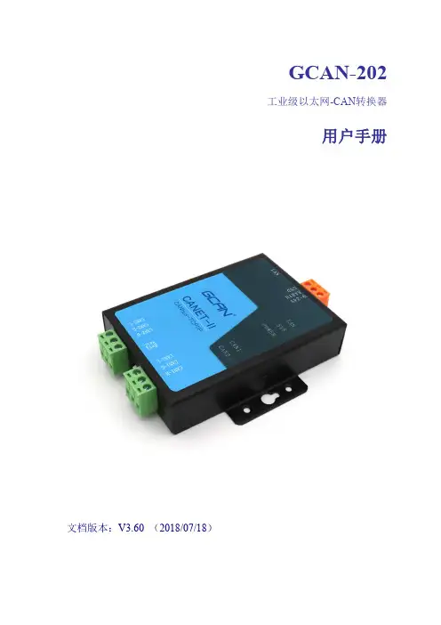
GCAN-202工业级以太网-CAN转换器用户手册文档版本:V3.60(2018/07/18)修订历史版本日期原因V1.002013/06/16创建文档V2.012013/12/20修正设备工作参数V3.122016/09/01添加部分参数V3.502017/01/10添加在线修改波特率功能V3.512017/06/19添加部分参数V3.522017/09/30修正部分参数V3.602018/07/18调整文档结构目录1.功能简介 (4)1.1功能概述 (4)1.2性能特点 (4)1.3典型应用 (5)2.设备安装 (6)2.1设备尺寸 (6)2.2接口定义及功能 (7)3.设备使用 (9)3.1与PC连接 (9)3.2与以太网连接 (10)3.3与CAN-bus连接 (12)3.4CAN总线终端电阻 (13)3.5系统状态指示灯 (13)4.CANet Config软件使用 (15)4.1恢复出厂设置 (15)4.2GCAN-202连接 (15)4.3配置通讯基本信息 (16)4.4配置完成 (18)4.5保存/加载配置文件 (19)4.6升级CANet固件内核(此功能请在指导下使用) (19)5.CANet简易测试软件使用 (21)6.网络调试助手使用方法 (22)6.1调试前准备工作 (22)6.2TCP Server模式通信测试 (23)6.3TCP Client模式通信测试 (24)6.4UDP模式通信测试 (25)6.5CAN口状态的TCP通知数据格式说明 (26)7.GCAN-202在线修改波特率功能 (27)7.1功能说明 (27)7.2格式说明 (27)7.3发送举例 (27)8.二次开发 (28)9.技术规格 (29)10.常见问题 (30)附录A:CAN2.0B协议帧格式 (31)附录B:GCAN-202(CANet)数据流定义 (33)1.功能简介1.1功能概述广成科技GCAN-202(CANET-II)是集成2路CAN接口、1路以太网接口的高性能型CAN-bus总线通讯接口卡。
手把手学配置FortiGate设备FortiGate CookbookFortiOS 4.0 MR3目录介绍 (1)有关本书中使用的IP地址 (3)关于FortiGate设备 (3)管理界面 (5)基于Web的管理器 (5)CLI 命令行界面管理 (5)FortiExplorer (6)FortiGate产品注册 (6)更多信息 (7)飞塔知识库(Knowledge Base) (7)培训 (7)技术文档 (7)客户服务与技术支持 (8)FortiGate新设备的安装与初始化 (9)将运行于NAT/路由模式的FortiGate设备连接到互联网 (10)面临的问题 (10)解决方法 (11)结果 (13)一步完成私有网络到互联网的连接 (14)面临的问题 (14)解决方法 (15)结果 (16)如果这样的配置运行不通怎么办? (17)使用FortiGate配置向导一步完成更改内网地址 (20)面临的问题 (20)解决方法 (20)结果 (22)NAT/路由模式安装的故障诊断与排除 (23)面临的问题 (23)解决方法 (23)不更改网络配置部署FortiGate设备(透明模式) (26)解决方法 (27)结果 (30)透明模式安装的故障诊断与排除 (31)面临的问题 (31)解决方法 (32)当前固件版本验证与升级 (36)面临的问题 (36)解决方法 (36)结果 (39)FortiGuard服务连接及故障诊断与排除 (41)面临的问题 (41)解决方法 (42)在FortiGate设备中建立管理帐户 (48)面临的问题 (48)解决方法 (48)结果 (49)FortiGate设备高级安装与设置 (51)将FortiGate设备连接到两个ISP保证冗余的互联网连接 (52)面临的问题 (52)解决方法 (53)结果 (60)使用调制解调器建立到互联网的冗余连接 (63)面临的问题 (63)解决方法 (64)结果 (70)使用基于使用率的ECMP在冗余链路间分配会话 (70)面临的问题 (70)解决方法 (71)结果 (73)保护DMZ网络中的web服务器 (74)面临的问题 (74)解决方法 (75)结果 (81)在不更改网络设置的情况下配置FortiGate设备保护邮件服务器(透明模式) (86)解决方法 (87)结果 (92)使用接口配对以简化透明模式下安装 (96)面临的问题 (96)解决方法 (97)结果 (101)不做地址转换的情况下连接到网络(FortiGate设备运行于路由模式) (101)面临的问题 (101)解决方法 (102)结果 (107)对私网中的用户设置显式web代理 (107)面临的问题 (107)解决方法 (108)结果 (110)私有网络的用户访问互联网内容的web缓存建立 (110)面临的问题 (110)解决方法 (111)结果 (112)应用HA高可用性提高网络的可靠性 (113)面临的问题 (113)解决方法 (114)结果 (118)升级FortiGate设备HA群集的固件版本 (120)面临的问题 (120)解决方法 (121)结果 (123)使用虚拟局域网(VLAN)将多个网络连接到FortiGate设备 (124)面临的问题 (124)解决方法 (124)结果 (129)使用虚拟域,在一台FortiGate设备实现多主机 (130)面临的问题 (130)解决方法 (130)结果 (137)建立管理员帐户监控防火墙活动与基本维护 (138)面临的问题 (138)解决方法 (139)结果 (140)加强FortiGate设备的安全性 (142)面临的问题 (142)解决方法 (143)为内部网站和服务器创建本地DNS服务器列表 (152)面临的问题 (152)解决方法 (152)结果 (154)使用DHCP根据MAC地址分配IP地址 (154)面临的问题 (154)解决方法 (155)结果 (156)设置FortiGate设备发送SNMP陷阱 (157)面临的问题 (157)解决方法 (157)结果 (160)通过数据包嗅探方式(数据包抓包)发现并诊断故障 (161)面临的问题 (161)解决方法 (162)通过数据包嗅探方式(数据包抓包)进行高级的故障发现与诊断 (170)面临的问题 (170)解决方法 (171)创建、保存并使用数据包采集过滤选项(通过基于web的管理器嗅探数据包) (179)面临的问题 (179)解决方法 (180)调试FortiGate设备配置 (184)面临的问题 (184)解决的方法 (185)无线网络 (195)FortiWiFi设备创建安全的无线访问 (196)面临的问题 (196)解决方法 (197)结果 (200)通过FortiAP在FortiGate设备创建安全无线网络 (200)面临的问题 (200)解决方法 (201)结果 (205)使用WAP-enterprise安全提高WiFi安全 (207)面临的问题 (207)解决方法 (208)结果 (211)使用RADIUS建立安全的无线网络 (212)面临的问题 (212)解决方法 (213)结果 (217)使用网页认证建立安全的无线网络 (218)面临的问题 (218)解决方法 (219)结果 (222)在无线与有线客户端之间共享相同的子网 (224)面临的问题 (224)解决方法 (224)结果 (227)通过外部DHCP服务器创建无线网络 (228)面临的问题 (228)解决方法 (229)结果 (232)使用Windows AD验证wifi用户 (234)面临的问题 (234)解决方法 (234)结果 (244)使用安全策略和防火墙对象控制流量 (245)安全策略 (245)定义防火墙对象 (247)限制员工的互联网访问 (250)面临的问题 (250)结果 (255)基于每个IP地址限制互联网访问 (255)面临的问题 (255)解决方法 (256)结果 (259)指定用户不执行UTM过滤选项 (260)面临的问题 (260)解决方法 (260)结果 (263)校验安全策略是否应用于流量 (264)面临的问题 (264)解决方法 (265)结果 (267)以正确的顺序执行安全策略 (270)面临的问题 (270)解决方法 (271)结果 (273)允许只对一台批准的DNS服务器进行DNS查询 (274)面临的问题 (274)解决方法 (275)结果 (278)配置确保足够的和一致的VoIP带宽 (279)面临的问题 (279)解决方法 (280)结果 (283)使用地理位置地址 (285)面临的问题 (285)解决方法 (286)结果 (288)对私网用户(静态源NAT)配置提供互联网访问 (288)面临的问题 (288)解决方法 (289)结果 (290)对多个互联网地址(动态源NAT)的私网用户配置提供互联网访问 (292)面临的问题 (292)解决方法 (292)不更改源端口的情况下进行动态源NAT(一对一源地址NAT) (295)面临的问题 (295)解决方法 (296)结果 (297)使用中央NAT表进行动态源NAT (298)面临的问题 (298)解决方法 (299)结果 (301)在只有一个互联网IP地址的情况下允许对内网中一台web服务器的访问 (303)面临的问题 (303)解决方法 (304)结果 (305)只有一个IP 地址使用端口转换访问内部web 服务器 (307)面临的问题 (307)解决方法 (308)结果 (310)通过地址映射访问内网Web 服务器 (311)面临的问题 (311)解决方法 (312)结果 (313)配置端口转发到FortiGate设备的开放端口 (316)面临的问题 (316)解决方法 (317)结果 (320)对某个范围内的IP地址进行动态目标地址转换(NAT) (321)面临的问题 (321)解决方法 (322)结果 (323)UTM选项 (325)网络病毒防御 (327)面临的问题 (327)解决方法 (328)结果 (329)灰色软件防御 (330)解决方法 (331)结果 (331)网络旧有病毒防御 (332)面临的问题 (332)解决方法 (332)结果 (333)将病毒扫描检测文件的大小最大化 (334)面临的问题 (334)解决方法 (335)结果 (336)屏蔽病毒扫描中文件过大的数据包 (337)面临的问题 (337)结果 (338)通过基于数据流的UTM扫描提高FortiGate设备的性能 (338)面临的问题 (338)解决方法 (339)限制网络用户可以访问的网站类型 (342)面临的问题 (342)解决方案 (342)结果 (343)对设定用户取消FortiGuard web过滤 (344)面临的问题 (344)结果 (346)阻断Google、Bing以及Yahoo搜索引擎中令人不快的搜索结果 (347)面临的问题 (347)解决方法 (347)结果 (348)查看一个URL在FortiGuard Web过滤中的站点类型 (348)面临的问题 (348)解决方法 (349)结果 (349)设置网络用户可以访问的网站列表 (350)面临的问题 (350)解决方法 (351)使用FortiGuard Web过滤阻断对web代理的访问 (353)面临的问题 (353)解决方法 (353)结果 (354)通过设置Web过滤阻断对流媒体的访问 (354)面临的问题 (354)解决方法 (355)结果 (355)阻断对具体的网站的访问 (356)面临的问题 (356)解决方法 (356)结果 (358)阻断对所有网站的访问除了那些使用白名单设置的网站 (358)面临的问题 (358)解决方案 (359)结果 (361)配置FortiGuard Web过滤查看IP地址与URL (361)面临的问题 (361)解决方法 (362)结果 (362)配置FortiGuard Web过滤查看图片与URL (364)面临的问题 (364)解决方法 (364)结果 (365)识别HTTP重新定向 (365)面临的问题 (365)解决方法 (366)结果 (366)在网络中实现应用可视化 (366)面临的问题 (366)解决的方法 (367)结果 (367)阻断对即时消息客户端的使用 (368)面临的问题 (368)结果 (369)阻断对社交媒体类网站的访问 (370)面临的问题 (370)解决方法 (371)结果 (371)阻断P2P文件共享的使用 (372)面临的问题 (372)解决方法 (372)结果 (373)启用IPS保护Web服务器 (374)面临的问题 (374)解决方法 (375)结果 (378)扫描失败后配置IPS结束流量 (378)面临的问题 (378)解决方法 (379)结果 (379)DoS攻击的防御 (380)面临的问题 (380)解决方法 (381)结果 (382)过滤向内的垃圾邮件 (382)面临的问题 (382)解决方法 (383)结果 (384)使用DLP监控HTTP流量中的个人信息 (384)面临的问题 (384)解决方法 (385)结果 (387)阻断含有敏感信息的邮件向外发送 (387)面临的问题 (387)解决方法 (388)结果 (388)使用FortiGate漏洞扫描查看网络的漏洞 (389)解决方法 (389)结果 (391)SSL VPN (392)对内网用户使用SSL VPN建立远程网页浏览 (393)面临的问题 (393)解决方法 (394)结果 (398)使用SSL VPN对远程用户提供受保护的互联网访问 (399)面临的问题 (399)解决方法 (400)结果 (403)SSL VPN 通道分割:SSL VPN 用户访问互联网与远程私网使用不同通道 (405)面临的问题 (405)解决方法 (405)结果 (409)校验SSL VPN用户在登录到SSL VPN时具有最新的AV软件 (411)面临的问题 (411)解决方法 (411)结果 (412)IPsec VPN (414)使用IPsec VPN进行跨办公网络的通信保护 (415)面临的问题 (415)解决方法 (416)结果 (420)使用FortiClient VPN进行到办公网络的安全远程访问 (421)面临的问题 (421)解决方法 (422)结果 (428)使用iPhone通过IPsec VPN进行安全连接 (430)面临的问题 (430)解决方法 (430)结果 (436)使用安卓(Android)设备通过IPsec VPN进行安全连接 (438)面临的问题 (438)结果 (443)使用FortiGate FortiClient VPN向导建立到私网的VPN (444)面临的问题 (444)解决方法 (445)结果 (449)IPsec VPN通道不工作 (450)面临的问题 (450)解决方法 (451)认证 (463)创建安全策略识别用户 (464)面临的问题 (464)解决方法 (464)结果 (466)根据网站类别识别用户并限制访问 (467)面临的问题 (467)解决方法 (468)结果 (468)创建安全策略识别用户、限制到某些网站的访问并控制应用的使用 (470)面临的问题 (470)解决方法 (471)结果 (472)使用FortiAuthenticator配置认证 (474)面临的问题 (474)解决方案 (475)结果 (478)对用户帐户添加FortiT oken双因子认证 (478)面临的问题 (478)解决方法 (479)结果 (482)添加SMS令牌对FortiGate管理员帐户提供双因子认证 (483)面临的问题 (483)解决方法 (484)结果 (486)撤消“非信任连接”信息 (487)解决方法 (488)日志与报告 (490)认识日志信息 (491)面临的问题 (491)解决方法 (492)创建备份日志解决方案 (497)面临的问题 (497)解决方法 (498)结果 (500)将日志记录到远程Syslog服务器 (502)面临的问题 (502)解决方法 (503)结果 (505)SSL VPN登录失败的告警邮件通知 (506)面临的问题 (506)解决方法 (507)结果 (509)修改默认的FortiOS UTM报告 (510)面临的问题 (510)解决方法 (510)结果 (512)测试日志配置 (513)面临的问题 (513)解决方法 (513)结果 (515)介绍本书《手把手学配置FortiGate设备》意在帮助FortiGate设备的管理员以配置案例的形式实现基本以及高级的FortiGate设备配置功能。
GPU\CPU协同并行计算非对称走时叠前时间偏移处理系统The A symmetric T ravel—time P re-S tack T ime M igration System(ATPSTM)by GPU\CPU C o-P rocessing P arallel C omputing(CPPC)用户手册USER’S MANUAL(因软件升级,请选择相应版本使用)北京吉星吉达科技有限公司Beijing Geo-Star Science & Technical Ltd.GPU\CPU协同并行计算非对称走时叠前时间偏移系统用户手册(试行版)2009年8月GPU\CPU协同并行计算(CPPC)非对称走时叠前时间偏移处理系统(ATPSTM)使用手册(试行版)内容导航1.编者前言......................................................................................................................................... - 4 -2.系统综述......................................................................................................................................... - 6 -2.1GPU\CPU协同并行计算机的构成 (6)1)GPU的发展历程 (6)2)GPU与传统CPU的主要区别 (6)3)GPU的优势 (7)2.2协同并行计算(CPPC)的概念 (8)2.3软件开发平台 (9)2。
4CUDA介绍 (9)3 安装与启动....................................................................................................................................- 11 -3。

gotone SIU™国通SS7网关系统用户手册©2007 版权所有广州国通信息技术有限公司版权声明最终用户软件许可协议许可:广州国通信息技术有限公司,将本软件程序的使用权授予您。
但您必须向本公司作以下保证:不在本协议规定的条款之外,使用、拷贝、修改、租赁或转让本系统或其中的任一部分。
本系统的版权和所有权:本系统及其所有拷贝的名称,与光盘上或本系统中注明的公司同在。
本系统及文档享有版权,并受国家版权法及国际协约条款的保护。
您不可以从本软件中去掉其版权声明;并保证为本系统的拷贝(全部或部分)复制版权声明。
您同意制止以任何形式非法拷贝本系统及文档。
目录版权声明 (2)目录 (3)警告与注意事项 (4)1.概述 (5)1.1.目的 (5)1.2.产品 (5)2.安装 (6)2.1.工作环境 (6)2.2.Telecommunications Compliance (6)2.3.部署拓扑 (7)2.4.前板指示 (8)2.5.后板指示 (8)2.5.1.PCM线路 (8)2.5.2.RJ45接口 (9)3.调试 (9)3.1.参数配置 (9)3.1.1.服务端 (9)3.1.2.客户端 (10)3.1.3.DLL端配置 (11)3.1.4.配置实例 (11)3.1.5.启动 (13)3.2.版权信息 (16)3.3.测试 (16)4.维护 (17)5.升级 (17)警告与注意事项警告WARNING:只有授权的服务工程师方可打开该设备。
在打开该设备之前请认真阅读相关操作手册。
QUALIFIED SERVICE TECHNICIAN OPERA TIONS:Only a qualified service technician is authorized to remove the Top Cover and to access any of the components inside the product. Before removing the Top Cover, read the manual carefully.警告WARNING:不要试图改变AC电源的任何参数。
SNMP/Web Card SC20G2Operation ManualInstallation∙ This document contains the information you need for using safely SNMP / Web card. Please read carefully before installation and use.∙Please keep it at hand carefully so that you can refer to it at any time, when this book is required.∙The copyright of this book belongs to OMRON SOCIAL SOLUTIONS Co.,Ltd.To copy, reproduce and reprint the contents partially or on the whole without notice to our company is refused firmly.∙The contents of this document are subject to change without notice.∙About a picture, it may differ from the newest thing in part.∙About Windows, and Windows NT and other names are the registered trademarks of U.S. Microsoft Corporation in the U.S. and other countries.∙Each other company names and each company product name are the trademarks or registered trademarks of each company.©OMRON SOCIAL SOLUTIONS CO.,LTD. 2014-2019. All Rights Reserved.Thank you for purchasing the OMRON SNMP/Web card lately⏹Correspondence specification∙T his product is equipment which makes network connection possible by inserting in the slot of the OMRON uninterruptible power supply (UPS).⏹Functional feature∙By inserting this product in an uninterruptible power supply (UPS), status acquisition from an uninterruptible power supply (UPS) and command issue to an uninterruptible power supply (UPS) areenabled.∙By inserting this product in an uninterruptible power supply (UPS), an uninterruptible power supply (UPS) is manageable even from the personal computer which does not carry a serial port.⏹Offer of automatic shutdown software∙Automatic shutdown software is enclosed by this product. (Please look at the newest information by our homepage.)∙It is possible to shut down by setup in the following cases.∙ When a main power supply system is downed∙ When the battery of an uninterruptible power supply (UPS) falls∙ When the connection capacity of an uninterruptible power supply (UPS) exceeds∙ When the temperature of an uninterruptible power supply (UPS) rises∙Automatic shutdown software and a script shutdown can perform schedule operation.∙ A computer can be safely suspended by automatic shutdown software and script shutdown.⏹Be related with the license of automatic shutdown software.∙You can use this product for two or more computers which perform shutdown via a network by installing it.⏹About export of this productWhen you wish issue of parameter sheet, please apply to our homepage.[Homepage address]https://www.oss.omron.co.jp/ups/support/export.htmlIn the case of an inquiry, the serial number of this product is required.I have indicated the serial number (S/N) on the seal of pasting at the container box side or themain part base back.Table of contentsInstallation (1)1.Before Using (3)1.1The check of enclosed items (3)1.2The name of each part of a main part (5)1.3Exchange of a bracket (5)1.4Functional outline (7)1.5System configuration (9)1.6About shutting down process (10)2.Insertion of a SNMP/Web card (11)work settings for SNMP / Web card (13)3.1Basic information about the IP address setting (13)3.2Network Configuration Method 1: via serial port (14)3.3Network Configuration Method 2: via telnet (18)3.4The contents of a setting via serial port / telnet (22)3.5Network Configuration Method 3: via web browser (26)4.Installation of automatic shutdown software (28)In order to prevent an injury, failure, a fire, etc., please be sure to read notes currently explained here.The sign and meaning about the safety of this operation manual are as follows.Attention If the mistaken handling is carried out, people get injured or the contentsgenerating of physical loss or damage is assumed to be are shown.*Physical loss or damage means the expansion damage concerning a house and household effects,livestock, and a pet.: It means prohibition (it must not carry out).For example, means the ban on decomposition.: It means compulsion (it must carry out).For example, means being connected by the ground.AttentionWhen you perform insertion and removal of this product , be sure to turn off the mainpart of an uninterruptible power supply (UPS) and connection apparatus, and to carryout in the state "AC input" plug is pulled out from a power receptacle.∙There is fear of an electric shock.Do not decomposition, repair, and reconstruction.∙There is a risk of receiving an electric shock or starting a fire.When you perform attachment and removal of this product to an uninterruptible powersupply (UPS), please work by installing an uninterruptible power supply (UPS) in thestable place and the direction which is not reversed.∙It may be injured if a falling and tumble occur.The uninterruptible power supply (UPS) furnished with this product should be carriedout ground connection (grounding) certainly.∙If an uninterruptible power supply and other apparatus contact simultaneously, without connecting a ground, an electric shock may be received.It is being unable to touch the parts on a substrate end face or a substrate, whenperforming the insertion and removal of this product.∙Since a substrate end face and parts are sharp, it may be injured if it touches. ∙There is a possibility of burning oneself if parts are high temperature. ∙ Parts sensitive to static electricity are being used for this product.Please do not touch the contact port and other parts of a connector in particularly empty-handed.A liquid cannot be touched even if a liquid is on an internal board.∙If it will be in such a state, please do not use it by any means. But please request the check and repair to the store or our company of a purchase. ∙There is a possibility of carrying out loss of eyesight and a burn. ∙ If it adheres to eyes or the skin, please wash away with a lot of clean waterimmediately, and receive a medical examination of a doctor.The "power supply" switch of the connected uninterruptible power supply (UPS) should be turned off and pulling out "AC input" plug from a power receptacle, when smoke, a nasty smell, and an abnormal sound occur from this product.∙ If it will be in such a state, please do not use it by any means. But pleaserequest the check and repair to the store or our company of a purchase.An operating condition and environment given in this description, and the operating condition and environment of the uninterruptible power supply (UPS) with which it is equipped are kept.The removed battery should not be put on the place which infants' hand reaches.∙ There is a risk that the infant swallow.A battery is not used for other uses. Do not disassemble, heated or dispose of in afire∙ Battery gets very hot, and there is a danger of explosion or fire+ and - of a battery are not short-circuited with wire etc.∙There is a risk of starting generation of heat and a fire Do not soak or do not pour water∙May cause a fire or electric shock ∙ When you soak in water, please stop use of this product immediately, andrequest check and repair. Do not leave the place to become the high temperature and a strong place of the direct lays of the sun.∙ Battery gets very hot, and there is a danger of explosion or fire1.1 The check of enclosed itemsPlease check whether there is any damage in the appearance of this product, or all the following packing articles are included.*When a packing article has fault and shortage, please ask the store of a purchase, or the OMRON electronic device customer support center.1.SNMP/Web Card 1 piece(BU-SW series, BU-RW series , BN-S series, BN-Rseries, BN-T series bracket attached )2.Bracket for exchange 1 pieceBN50T, BN75T, BN100T, BN150T,BN220T, BN300TBN50S, BN75S, BN100S, BN150S,BN100XR, BN150XR,Please refer the following web page for details.(https://www.oss.omron.co.jp/ups/)3.Serial connection cable1 piece4. CD-ROM 1 piece(Instruction manual, shutdown software, etc.)5.Installation instruction (Japanese/English) 2 pieces2 pieces 6.Warranty card (in end of Installation instruction.Japanese/English)1.2 The name of each part of a main partThe name of each part of a SNMP/Web card is as follows.1.3 Exchange of a bracketThe screw hole position of a slot changes with uninterruptiblepower supply (UPS) model. Please exchange brackets if needed.It is exchange needlessness when connecting it with follows.BU50SW/BU75SW/BU100SW/BU150SW, BU1002SW/BU3002SW,BU75RW/BU100RW/ BU200RW/BU300RW,BN50S/BN75S/BN100S/BN150S/BN220S/BN300S/BU60RE/BU100RE/BN75R/BN150R/BN300R/BN50T/BN75T/BN100T/BN150T/BN220T/BN300T /BU1002RW/ BU2002RWL/BU3002RWL/BU5002RWLPlease refer the following web page for details.(https://www.oss.omron.co.jp/ups/)Please exchange for an attached exclusive bracket, When you connect it withBracket forBN50T, BN75T, BN100T, BN150T, BN220T, BN300T BN50S, BN75S, BN100S, BN150S, BN220S, BN300S BN75R, BN150R, BN300RBU50SW, BU75SW, BU100SW, BU150SWBU75RW, BU100RW, BU200RW, BU300RWBU60RE, BU100REBU1002SW, BU3002SWBU1002RW, BU2002RWL, BU3002RWL, BU5002RWL Bracket forBN100XR/BN150XR/BN240XR1.4 Functional outline⏹Direct connection of an uninterruptible power supply (UPS) and a network∙By inserting into an uninterruptible power supply (UPS) this product, you can manage an uninterruptible power supply (UPS) from any computer that is not equipped with a serialport.∙By inserting into an uninterruptible power supply (UPS) this product, you can manage an uninterruptible power supply (UPS) from a Web browser and SNMP managersoftware available on the market.⏹Remote monitoring of the uninterruptible power supply (UPS) on thenetwork∙From all workstations on the intranet and the Internet, you can remotely monitor the uninterruptible power supply (UPS).⏹You can set the function of SNMP / Web card and the uninterruptible powersupply (UPS) from a computer on the network∙Parameter settings for SNMP / Web card and the uninterruptible power supply (UPS) can be carried out in the Internet browser or via any of the SNMP managementstation. (Function as an SNMP agent can be set over a serial connection and Telnet.)∙Display the contents of the parameter setting screen is automatically changed according to (presence or absence of output outlet control function) the contents of thefunction of the uninterruptible power supply (UPS), only the required setting items aredisplayed.⏹Enhanced security features∙It corresponds also to HTTPS and SNMPv3 in addition to HTTP andSNMPv1. (Cautions) Access by HTTPS can be accessed by Open SSLver.2.0.Access by HTTPS cannot be performed in some browser software(Firefox etc.).⏹Mail Notification∙You can send a notification email to the address that you specified in advance in the event of a power failure, etc.⏹Log function∙The power failure (UPS), power status, battery status and uninterruptible power supply can be stored in flash memory in the product.∙It corresponds to Syslog.⏹Automatic shutdown function∙By installing the enclosed automatic shutdown software, the predetermined shutdown which the administrator programmed beforehand, or a shutdown whenserious power failure occurs is performed automatically.⏹The function corresponding to Wake ON LAN∙By registering a maximum of 32 MAC Addresses of client PC which has equipped the WakeOnLAN function, all the client PCs can be rebooted at once with a Wake ONLAN signal at the time of an uninterruptible power supply (UPS) reboot after theshutdown by the signal from an uninterruptible power supply (UPS).⏹Standard MIB (RFC1628) and original MIB (swc mib) of an uninterruptiblepower supply (UPS) are equipped.⏹Using a JAVA applet, the state of a power supply is monitored∙By a graphical representation, the state of a power supply can be checked visually.⏹Script shutdown∙You can shut down the computer from the network by incorporating the script without using the auto-shutdown software.⏹Down monitoring∙Monitored via a network device that is connected to an uninterruptible power supply (UPS), you can stop / start the output of the UPS when an error occurs.⏹CO2 setting∙The result of having computed the carbon-dioxide emissions of the apparatus (whole) connected to the uninterruptible power supply (UPS) is displayed.1.5 System configuration∙It is possible to back up multiple computers on a network of mixed various OS, to perform the shut down during a power failure.∙System configuration example1.6About shutting down process⏹ When you use the automatic shutdown∙ If such power failure occurs, you can run the shutdown process by using a function ofthe automatic shutdown software. With this process, you can stop your computer safe.Power failure occurs Power downUPS (BU300RW)Auto stop Back UpOperation startShutdown StartWait time for the end of applicationAutomatic shutdown software receives a shutdown command.⏹ When a script shutdown is used∙ When power failure etc. occurs, a shutdown process is executed using the function of ascript shutdown. By this processing, a computer can be suspended safely.Power failure occurs. Power downUPS (BU300RW)Auto stop Backup Operation startShutdown StartWait time for the end of applicationAutomatic shutdown software receives a shutdown command.* It does not mean that the shutdown is possible in the script on all devices . Please perform a pre-operation check whenever you use this function.Insertion procedureBU200RW/BU300RW BN220S/BN300S Please connect an uninterruptible power supply (UPS) with a power receptacle, and turnAttention (attachment and removal )When you perform insertion and removal of this product , be sure to turn off the main part of an uninterruptible power supply (UPS) and connection apparatus, and to carry out in the state "AC input" plug is pulled out from a power receptacle. ∙ There is fear of an electric shock.When you perform attachment and removal of this product to an uninterruptible power supply (UPS), please work by installing an uninterruptible power supply (UPS) in the stable place and the direction which is not reversed.∙ It may be injured if a falling and tumble occur.It is being unable to touch the parts on a substrate end face or a substrate, when performing the insertion and removal of this product.∙ Since a substrate end face and parts are sharp, it may be injured if it touches. ∙ There is a possibility of burning oneself if parts are high temperature. ∙Parts sensitive to static electricity are being used for this product.Please do not touch the contact port and other parts of a connector in particularly empty-handed.3.1Basic information about the IP address settingA setup for using this product on the target network is performed.The fixed IP address of the initial value of this product is set as "192.168.2.150."Please make a change of an fixed IP address from [SMNP-Web-Card Configuration Utility Main menu] of a "method 1: via serial port “or a "method 2: via Telnet"Settings through a Web browser can be useful after performing a set of network-related once.Please refer to: "3.3 Network Configuration Method 2 :via Telnet " or " 3.2 Network Configuration Method 1: via serial port "This book explains Windows8.1 to an example. When you use other OS's, please perform a setup for the following contents to reference.3.2 Network Configuration Method 1: via serial portSetup stepsPlease download Tera Term Pro from Internet, and create shortcut to adesktop.*1Please double-click the shortcut of Tera Term Procreated to the desktop.*1 There are cases where the terminal software is not installed by the OS to be used. In that case, please set up after preparation separately.Since the screen for setting up the property of the set-up COM port is displayed,Please press the Enter key.Next, since the following password entry screensThe item of [SNMP-Web-Card Configuration Utility Main menu] is displayed. displayed.Furthermore, please input "1" and push.After inputting the number of an item to change, please push .Next, after inputting a value and completing an input, please push .3.3 Network Configuration Method 2: via telnetPlease set up TCP/IP by computer for a setup as follows.Setup steps of TCP/IPPlease click [OK] after a setup and return to an initial screen.Configuration procedures in this productThe following command prompt screens are displayed.192.168.2.1503.4 The contents of a setting via serial port / telnet⏹When setting up via a serial port/TelnetThe following [SNMP-Web-Card Configuration Utility Main menu] is used. It is possible to set up almost all functions via a serial port except for a shutdown-related function.To set up, it is necessary to certainly carry out by serial connection or Telnet. (*Setting recommendation by the connection via Telnet)⏹The contents of a setting of [SNMP-Web-Card Configuration Utility Mainmenu]1. SNMP-Web-Card Configuration2. Uninterruptible power supply(UPS)Parameters3. Access Control Table∙ 4. Trap Receiver Table∙ 5. Main Window∙ 6. Reset Configuration To Default ∙7. Restart Agent∙0. Exit3.5 Network Configuration Method 3: via web browserIn the following cases, it is possible to set up a SNMP/Web card via a web browser.∙When an IP address is acquired from a DHCP server∙When a setup of an IP address is completed via a serial port or Telnet Setup steps5 The initial screen of a SNMP/Web card is displayed.By installing PowerAct Pro Slave Agent of enclosed automatic shutdown software in this product, the automatic shutdown by the time of power failure or a schedule is possible.For installation instructions, please refer to the instruction manual of the automatic shutdown software.∙ Please check our homepage (https://www.oss.omron.co.jp/ups/) for the newest product information.Each company name and each company product name are the trademarks or registeredtrademarks of each companyCarrying out unapproved reproduction of a part or all of the contents of this operationmanual is forbidden.It may change without a preliminary announcement about the contents of this operationmanual in the future.©OMRON SOCIAL SOLUTIONS CO.,LTD. 2014-2019. All Rights ReservedOMRON SOCIAL SOLUTIONS CO.,LTD.K1L-D-14028B。
Graphical Network Simulator简介GNS3是一个可以模拟复杂网络的图形化网络模拟器,它可以运行在Windows、Linux、MAC OS上,允许你在虚拟环境中运行Cisco IOS。
GNS3是dynagen的图形化前端,用于搭建网络TOP,并生成dynagen所可以加载的net文件,用来加载Cisco IOS 的核心程序是dynamips.GNS3 0.7.2可以模拟Cisco Router、Cisco ASA、Cisco PIX、Cisco IDS/IPS、Juniper Router以及通过路由器加载交换模块实现部分交换功能;通过其所带的qemu还可以运行虚拟主机;程序还可通过Wireshark来抓取虚拟网络TOP中的数据包。
GNS3的安装目录、以及首选项中的各个选项卡,在需要配置目录或者选择文件时,路径中都不要带有中文。
以下为一些有用的网站: GNS3’s primary Web site GNS3’s Wiki sitehttp://www.ipflow.utc.fr/blog/Dynamips blog/Dynagenhttp://www.ipflow.utc.fr/bts/Dynamips/Dynagen bug tracking http://7200emu.hacki.at Hacki’s forum/bbs/Netemu虚拟化先锋无忧网客联盟GNS3 Quick Start Guide for Windows Users1、下载GNS3 0.7.2/project/gns-3/GNS3/0.7.2/GNS3-0.7.2-win32-all-in-one.exe 2、安装GNS3 0.7.2,一路next就行(win7用户需要关闭系统防火墙):3、GNS3可以模拟的思科路由器型号如下:的一些参数。
GNS3界面如下:快捷命令按钮介绍:选择“编辑”-->“IOS和hypervisors”来配置IOS以及Hypervisors在“IOS”选项卡进行IOS的添加4、首选项配置:默认安装后,界面为英文,进入“Perferences”设置,如图:“General”设置有3个选项卡:整体设置、终端软件设置、GNS3的GUI设置:Dynamips:包含了dynamips的一些特性的配置和hypervisors的配置Capture:抓包软件的设置Qemu的配置:这里的配置将结合GNS3模拟ASA,Juniper的时候进行介绍。
NetApp存储系统C-mode操作手册2016.3.23目录1.基本配置 (3)1.1.聚合配置 (4)1.2.网络配置 (5)1.3.日期和许可配置 (11)2.SVM管理及配置 (14)3.SVM的卷管理 (18)3.1.创建卷 (18)3.2.编辑卷 (19)4.命名空间管理 (25)5.导出策略配置 (26)6.协议配置 (28)Data Ontap 8.3版本后,不再需要安装system manager管理软件,8.3 版本内嵌system manager管理软件,在浏览器输入集群的管理地址即可实现对存储系统的图形化管理。
1.基本配置打开浏览器,输入集群的管理地址。
出现登录界面。
输入集群的用户名和密码。
点击“登录”按钮。
在该页面可以查看集群的基本信息,如集群名称、Data Ontap版本、警报、容量等。
单击“集群性能”选项卡,可查看系统性能。
1.1.聚合配置在左侧单击“存储”>"聚合",进入聚合配置页面。
一般情况下,聚合会由NetApp工程师在初始安装完成创建,不需要用户自行创建。
在该页面下,可对聚合进行编辑、扩容、增加缓存、镜像等操作。
单击“磁盘”选项卡,在该页面可以查看磁盘的基本信息,单击“清单”选项卡,可以查看每一块物理硬盘的信息。
1.2.网络配置单击“配置”>“网络”进入网络配置页面。
在网络配置中,可创建端口聚合,VLAN,配置端口lif等。
每个SVM都必须创建端口lif,才能进行数据访问。
单击“以太网端口”选项卡。
这里会显示系统中的所有以太网口,包括每个节点的以太网口,因此在配置上,要注意,不要选错了节点。
单击“创建端口组”选项卡1.编辑端口组名称。
默认为a0a。
2.选择节点。
每个节点就是存储的一个控制器。
3.选择模式。
有single、multipath、Lacp三种模式。
4.选择负载均衡策略。
单击“创建”选项卡,完成配置。
完成接口组创建口,在以太网端口下会显示刚创建的以太网接口组。

NT手持表操作手册说明书带有数据记录多功能用来测量流率,流速,温度,压力和其他变量的手持式表。
控制元件和连接件的概述和简要介绍。
!,请确保选择正确的传感器(FA,VA或TA)(看下面5.3.19)!目录1,安全说明1.1具体参数1.2操作电池2,交货范围描述,排列模板3,技术参数,运行条件,外壳和连接,电气参数,测量不确定性4,初始操作/启动,连接插头,8针连接插头的线路图, 12针连接插头的线路图4.3.1 模拟输出 0-10V 4.3.2 模拟输入 4-20mA4.3.3 模拟输入 0-10V5.操作,按键功能,开启后设置菜单,参数设置6,检修7,替换零件8,种类3G安装手册9,种类3G符合标准说明1,安全说明损坏及受损风险导致的损失。
在初始操作前请仔细阅读操作手册说明。
遵守一般安全措施也包含在这操作说明书中的其他部分。
危害风险-不按照操作和安全说明。
-客户自己更改设备。
-不按照指定的操作条件处理设备-不按照指定的操作条件处理探头-使用不合适的电源和外围设备。
-设备的使用不当。
预防电压危害-交流电源上仅使用专用的适配器插头-当使用USB接头时确保电脑是正确的连接在电源上(接地安全插座,接地)-当类似输出或输入连接到外围设备上时确保他们正确的连接到电源上(接地安全插座,接地)当加压管道上安装传感器的危险-传感器仅用在加压管道中的插入或减压条件中的折回。
不遵守可能严重导致人员受伤。
-在压力情况下安装或拆卸,必须使用必要的防护设备。
例如:球阀和带有防护链的探杆或主轴探杆。
在爆炸环境中使用备件的危险。
-该装置和它的传感器或仅用在种类3G(区域2 气体)的范围设备内。
-当标有种类1/2G,1/2D或2G,2D或3D的传感器连接到设备上,他们只能用在种类3G区域!(参照操作手册种类3G和第八第九部分的符合标准说明)。
具体参数-当使用电压变化时注意电源电压。
-通过使用超过12V电源来连接传感器检测最大额定功率。

1、基础配置1.1、初始化配置通过Console口进行本地登录是登录设备的最基本方式,也是配置通过其他方式登录设备的基础。
PC机或终端服务器必须配置如下:115200 baud1 stop bit8 data bitsNo flow controlNo parity bits当交换机启动时flash没有包含初始配置脚本,它会进入ZTP自动配置模式,直到用户退出ZTP模式或交换机获得初始化脚本。
当交换机通过ZTP获得配置脚本,它会自动用获得的文件重启交换机。
在ZTP模式下,按‘c’ or “C”进入配置菜单:1 - Start xNet2 - Download_config3 - Update4 – Backup5 – Restore 6– Reboot1.1.1Start xNet按“1”启动系统。
Press C to enter configuration menu.If no selection is made within 3 seconds,the xNet will go to start procedure...configuration menu (c | C): cxNet -- Config Menu1 - Start xNet2 - Download_config3 - Update4 - Backup5 – Restore6 – RebootSelect option (1-6): 1System Drive loadingLoading SuccessWelcome to xNetware1.1.2Download_config按“2”下载配置脚本。
Select option (1-6): 2Enter TFTP Server IP []:4.4.4.4Enter Host IP [10.204.252.112]:4.3.2.1Enter Host Subnet Mask [255.255.252.0]:255.0.0.0Enter Filename []:my.confBringing up eth1 interface...done.Download the my.conf from tftp serverDownload complete1.1.3Update按“3”下载tar.gz文件。
TiNet S2000B 快速以太网交换机用户手册版本号:V1.0出版日期:<2008-08-01>深圳市新格林耐特通信技术有限公司修订记录Version Control声明深圳市新格林耐特通信技术有限公司,版权所有。
未经本公司的书面许可,不得以任何形式或手段翻译、摘抄、复制本手册的任一章节。
目录TiNet S2000B 快速以太网交换机 (1)第一章访问设备 (1)1.1访问方式 (1)1.2登录配置 (1)1.3用户登录 (1)第二章交换机管理 (4)2.1口令设置 (4)2.2系统IP设置 (5)2.3系统状态 (5)2.4恢复默认值 (6)2.5固件升级 (7)2.6设备重启 (8)第三章端口设置 (9)3.1端口配置 (9)3.2端口镜像 (10)3.3带宽控制 (11)3.4广播抑制 (11)3.5端口报文计数 (12)3.6端口Trunk设置 (13)第四章VLAN设置 (14)4.1VLAN模式 (14)4.2VLAN成员 (15)4.3VLAN快速设置 (17)第五章Qos设置 (18)5.1优先级模式 (18)5.2优先级类型 (19)5.3基于TCP/UDP的QOS (20)第六章报文安全过滤 (22)6.1MAC地址绑定 (22)6.2TCP/UDP过滤 (22)第七章配置备分与恢复 (24)7.1 配置备分与恢复 (24)第八章其他功能 (25)8.1 其他功能 (25)第九章页面超时及退出 (26)9.1页面超时 (26)9.2 退出 (26)第十章硬件恢复默认值 (27)10.1 硬件恢复默认值 (27)附录 (I)附录1 常见故障诊断 (I)附录2 术语解释 (II)附录3 网线制作 (III)RJ-45连接器 (III)网线制作 ................................................................................................. I V前言内容介绍本手册对TiNet S2000B(F)快速以太网交换机的各主要特征进行了详细地介绍。
MASTERGUARD (SIEMENS)不间断电源(UPS)MP-NET系列80KVA日常操作及维护深圳市博力科技有限公司编译二零一零年三月目录 (2)一、UPS接线检查和上电及开关机程序 (3)二、控制面板和LCD指示 (6)三、UPS运行维护 (14)四、MP-NET系列技术数据 (16)德国MASTERGUARD MP-NET系列UPS开机/关机程序:如果UPS超过一年时间没有使用,中间电路电容需要格式化(预充电)。
如果在交货后一年之内对UPS进行过调试,就没有必要格式化了。
调试过程如下:一.UPS的接线检查和上电及开关机程序移除盖板1. 检查UPS的接线是否正确2. 确保通风栅畅通。
3. 确保地线接地。
4. 确保每个外部开关处于“断开”(OFF。
5. 确保外部电池开关处于“断开”(OFF)6. 确认门插销在位置7. 确认地线和零线之间没有电压8. 确认输入电源与你安装的UPS额定电压、频率、相位和电池等匹配Q1:主输入断路器 Q2:旁路输入断路器Q3:维护旁路输入断路器 Q4:输出断路器1、正常启动程序(1)假如有外部电池柜,闭合外部电池柜断路器,确认Q3打开(2)闭合Q2和Q4。
LCD在初始化之后将显示旁路工作,,在此期间,UPS输出由旁路供电,LED “旁路”指示灯亮(3)闭合Q1,如果输入电源正常,UPS准备启动(4)按“I”按钮3秒直到听到一声嘟嘟声释放按钮,逆变器启动,输出将由逆变器供电,“旁路”指示灯灭“正常”指示灯亮2、电池启动程序(1)闭合外部电池断路器,确认Q3打开(2)按“I”按钮3秒直到听到一声嘟嘟声释放按钮(3)UPS平稳启动通过DC-BUS,逆变器启动(4)逆变器为输出供电,“电池“指示灯亮3、关闭程序这个程序将关闭UPS和负载输出,首先确认所有负载已经关闭(1)按“O”按钮3秒直到听到一声嘟嘟声释放按钮,LCD将显示“关闭UPS?”然后选择“YES”和按键确认如果UPS在正常模式:UPS将切换到旁路模式,LCD显示“旁路工作”如果UPS在电池模式:UPS将关闭逆变器,切断输出电源(2)打开Q1(3)打开Q2(4)确认UPS关闭和所有断路器断开(5)假如有外部电池柜,断开外部电池柜断路器(6)打开Q44、维护旁路启动程序从在线模式切换到维护旁路模式如果UPS在正常模式,按“O”按钮3秒直到听到一声嘟嘟声释放按钮,LCD将显示“关闭UPS?”然后选择“YES”和按键确认,UPS将自动切换到旁路模式工作。
G-NET城市燃气管网水力分析软件操作手册中国市政工程华北设计研究院北京赛远科技发展有限公司目录第一节概述第二节软件环境及安装2-1 软件环境2-2 软件安装2-3 安装说明第三节软件处理流程及算法3-1 处理流程3-2 主要算法第四节软件操作方法4-1 开始操作4-2 软件运行操作方法4-2-1 【专业绘图】功能模块操作方法4-2-2 【数据准备】功能模块操作方法4-2-3 【管网分析】功能模块操作方法4-2-4 【辅助工具】功能模块操作方法第五节水力分析的计算依据5-1 低压管网5-2 中、高压管网第六节结束语第一节概述:燃气管网分析软件基于Windows98/2000/Me/XP 操作系统,其中绘图则基于AutoCAD R14/R2000/R2002,具有良好的操作界面和方便的操作方法,适用于天然气、煤气、油煤气、气态液化石油气、液化石油气空气混合气及矿井气等燃气在高中压及低压等不同的压力级制下的环网的水力分析和计算。
软件主要具有如下特点:●充分利用Win32优越的内存管理功能,理论上计算管段数目只受计算机内存的限制。
●管网分析计算与绘图一体化。
●在自识别环路管网图的基础上,自动对环、管段及节点编号处理、自动设定管段流向。
●符合修订规范要求、同时兼容原规范要求。
●采用多种方式进行原始数据输入方式灵活,编辑方便。
●分析结果以图形方式、文档方式及分析过程等多种方式输出。
●采用先进的图形处理算法及迭代算法,在传统的节点方程法基础上采用变带宽矩阵存储系数矩阵,因为系数矩阵是一对称稀疏矩阵,运用变带宽技术可以节省大量的存储空间,使有限的内存可以计算的管段数有倍数级的增加。
●COM组件模式。
●易于操作,使用者短时间内即可熟练掌握。
第二节软件环境及安装2-1 软件运行环境G-NET(V1.0)是以ACADR14为绘图平台,G-NET (V2.0)是以ACADR2000/2002为绘图平台,操作环境为WIN9X/WINNT/WIN2000/XP。
在今后将陆续推出以WINDOWS为平台的WIN版本。
CAD版本硬件基本要求如下表:2-2软件安装方法1、将光盘放入光驱后,执行光盘中的setup.exe命令(双击其文件或图标)即可开始执行安装G-NET软件。
2、在安装过程中,用户须给定软件的安装目录,其余点取NEXT按钮,直至安装完毕。
我们这里假定用户的安装目录是C:\GAS。
2-3 说明:软件安装成功后,所有的文件都在C:\GAS 目录下其中主要文件说明如下:〃main.exe运行主程序。
〃gwpcjs.exe静态分析计算执行程序,可独立运行。
〃gwpc.exe图形分析及数据准备程序,需在AutoCAD环境中运行。
〃drive 软件的驱动程序〃sys程序运行文件〃sample给出一些图形及工程定义文件的例子。
第三节处理流程及算法3-1 处理流程:3-2主要算法:假定各管段λ均为1,计算各管段的阻耗和导纳,组成管网的节点导纳矩阵,由矩阵方程[Y][P]=Q求出管网节点压力p,由A T[P] = ΔP求得管段压力降,再由Q = G[ΔP]求得管段初始流量。
根据以上步骤求得的初始管段流量,重新计算各管段的阻耗和导纳,组成新的导纳矩阵,重复上述步骤,进行迭代计算,直到前后两次的Q之差值达到精度要求。
第四节软件操作方法重要提示:为清晰起见,以下字体中凡斜体部分均为软件在运行时的提示语句。
需特别注意的事项则用黑体字。
4-1 开始:本软件的操作主要包括图形处理及计算分析两部分,其中图形处理是为计算分析做准备的。
有了图形处理过程,计算分析所需的各种管网数据结构及节点流量等参数的输入将十分方便,且均为自动处理,为设计人员节约不必要的资源浪费。
事实上,计算分析部分可以独立使用,但需设计人员自行给管网中各节点、管段等编号,设定各管段流向等繁琐的操作。
1、软件安装成功后在桌面生成一个图标2、双击此图标进入软件的主界面(见图一)(图1软件主界面)1、此界面为G-NET软件的主控界面:主要有以下几个功能模块:※【新建工程文件】(见图二)——新建一个工程文件。
*.prg文件※【打开已有工程】(见图三)——打开已有工程文件进行水力计算。
※【图形拓扑分析】——点击可进入绘图环境进行环网图形准备与处理功能。
※【管网水力计算】——点击可直接进行已有工程文件的环网水力计算。
※【管网动态分析】——此功能在以后版本中推出。
※【软件功能介绍】——G-NET软件的综合介绍。
※【退出系统】4.根据需要点击按钮进入各功能模块。
(图2新建工程文件)(图3打开已有工程文件)4-2 软件运行操作方法4-2-1【专业绘图】功能模块操作方法:1.点击【新建工程文件】模块中【进入绘图环境】进入G-NET/ACAD软件运行环境。
2.G-NET软件可以接受用户原有的环网图、地形图或者自己在绘图环境中建立环网图3.在绘制环网图之前需要注意的是绘制过程中的两个统一,即比例和图层统一:比例统一,如1米可绘制成1绘图单位或500、1000、10000绘图单位等。
图层统一,图名可任意,但在必须同一层上,添加的虚管段也如此。
线段端头,线段端头处的连接应借助捕捉功能以准确绘制。
4.软件提供三种绘制管段的方法:【直接绘制管段】【按参考线绘制管段】【动态绘制管段】如图。
注意:用户在直接绘制出框架图形,由于用户在绘制过程中没有考虑线段环网的关系,此图中直线间并没有打断并形成一个环的概念。
所以用户需要再通过【辅助工具】→【直线集相互打断】功能自动处理相交点,使绘制复杂的管网图也十分快捷。
提示如下:************ 直线交点互相打断程序V1.0 ************点取所在图层代表:选择操作集(回车放弃):Select objects: all 8 foundSelect objects:正在建立数据...正在分析数据...共处理有交点的LINE实体8 个。
操作完毕!5.【生成分析草图】按钮在用户做完以上绘制工作后要使用此功能生成计算草图。
提示如下:****** 环路管线计算草图生成程序V1.0 *********点取代表线段:正在构造...正在分析...生成计算草图及节点编号...注意:共完成8个环路,15个节点,22条管线的绘制。
操作完毕!在随后出现的输入草图文件名的对话框中指定草图文件名为CT.dwg,存放在任意位置即可。
6.【节点优化分析草图】按钮注意:在很多实际工程中需要处理管段上许多在以后计算中不需要的节点或折点是很烦琐的。
此程序模块通过对管段上节点的优化处理就很好地解决了这个问题,给设计人员的工作提供了很大的便利。
并大大提高了工作的效率。
例图:以下是一个没经过节点优化处理的工程节点草图:使用【节点优化分析草图】功能后节点草图如下7.【打开分析草图】按钮打开刚才生成的计算草图CT.dwg如下;关于虚管段的作用:如果管网图形中有环连环(即两个环集合间只有单条管段回路连接)或环连支管这种情况,则须绘制虚管段,绘制虚管段时以形成的新的闭合环(是个虚环)的边数最少为宜。
只是这些辅助的虚管段在下一步输入管径时为0即可。
参见下图:4-2-2【数据准备】功能模块操作方法:在已绘制完成的环网图中进行数据的准备工作。
此模块的功能如下:1.在以上草图中确定【设置气源点】按钮为执行[设置气源点]命令提示如下:********** 低压调压站设定及编辑程序**********选择设定为调压站的节点圆实体: 点取图中3号节点输入该调压站的流量(立方米/小时)<回车不输>:输入该调压站的压力(帕pa)<回车不输>:1500设定完成!选择设定为调压站的节点圆实体:点取图中8号节点输入该调压站的流量(立方米/小时)<回车不输>:输入该调压站的压力(帕pa)<回车不输>:1500设定完成!选择设定为调压站的节点圆实体:操作完毕!注意:操作完成后在分别在3号和8号节点处用红色圆以醒目表示。
如果某节点被设置错了,可执行同一命令后点取该节点圆,只是在提示输入流量和压力时空回车即可。
需要注意的是,若用户对提示输入流量和压力均作了输入,则只有压力为有效输入。
2.【设置储气站】按钮为此功能提供管网中设置储气站功能,提示如下:********** 储气站设定及编辑程序**********选择设定为储气站的节点圆实体:输入该储气站的流量(立方米/小时)<回车不输>:1500选择设定为储气站的节点圆实体:操作完毕!3.【流量统一输入】按钮为3-1.执行此功能必须先调用【工程文件】*.prg 。
提示的界面如下:3-2.在此用户可根据需要人工输入确定【环流量】的参数、【集中流量】的参数后,在进行环网流量的校核。
3-3.校核完毕后【存盘退出】。
在用户的工程目录下生成*.004 ,和*.005文件。
做为以后按环流量分配节点流量的必须文件。
4.节点流量的确定:4-1【直接给定节点流量】按钮用户人工给定每个节点的流量,操作提示如下:******* 管网节点流量输入程序V1.0 ************以下将直接输入各节点的流量(单位:立方米/秒)。
输入显示节点的流量(立方米/秒):< 0.0000>:201输入显示节点的流量(立方米/秒):< 0.0000>:400输入显示节点的流量(立方米/秒):< 0.0000>:375输入显示节点的流量(立方米/秒):< 0.0000>:425输入显示节点的流量(立方米/秒):< 0.0000>:850输入显示节点的流量(立方米/秒):< 0.0000>:414输入显示节点的流量(立方米/秒):< 0.0000>:190输入显示节点的流量(立方米/秒):< 0.0000>:325输入显示节点的流量(立方米/秒):< 0.0000>:205输入显示节点的流量(立方米/秒):< 0.0000>:405输入显示节点的流量(立方米/秒):< 0.0000>:425输入显示节点的流量(立方米/秒):< 0.0000>:425输入显示节点的流量(立方米/秒):< 0.0000>:200提示:可直接用ACAD的文字编辑功能ddedit改动标注的流量数据.操作完毕!完成后如下图所示:注意:1.节点流量为正表示流出节点,反之为负。
2.如果要对某节点流量做改动,例如上图中5号节点处增加集中流量100m3/h,可通过文字编辑命令ddedit直接将425.0改为525.0即可。
4-2.【按环流量分配节点流量】按钮为A:首先要调用工程文件,根据以上004和005文件程序自动分配各节点流量:B:如要编辑,方法同前。