超短焦激光投影机安装说明 PPT
- 格式:ppt
- 大小:1.79 MB
- 文档页数:24
超短焦互動投影機型號UM352W使用手冊保留備用Ver. 1 3/15•Apple、Mac、Mac OS、MacBook和iMac為Apple Inc. (蘋果公司)在美國和其他國家註冊的商標。
App Store是Apple Inc. (蘋果公司)的服務標記。
•iOS為Cisco在美國和其他國家的商標或註冊商標,經許可使用。
•Microsoft、Windows、Windows Vista、Internet Explorer、.NET Framework和PowerPoint為Microsoft Corporation (微軟公司)在美國和/或其他國家的註冊商標或商標。
•MicroSaver為ACCO品牌的一個分公司Kensington Computer Products Group的註冊商標。
•Virtual Remote Tool (虛擬遙控工具)使用WinI2C/DDC library, ©Nicomsoft Ltd.•術語HDMI、HDMI High-Definition Multimedia Interface和HDMI標誌是HDMI Licensing LLC在美國和其他國家的商標或註冊商標。
•MHL、Mobile High-Definition Link和MHL標誌為MHL, LLC的商標或註冊商標。
•PJLink商標在日本、美國和其他國家與地區已申請商標權。
•Wi-Fi®、Wi-Fi Alliance®、Wi-Fi Protected Access®和Wi-Fi Direct®為Wi-Fi Alliance®的註冊商標。
WPA™、WPA2™、Wi-Fi Protected Setup™和Miracast™為Wi-Fi Alliance®的商標。
•Blu-ray為Blu-ray Disc Association (藍光光碟協會)的商標。


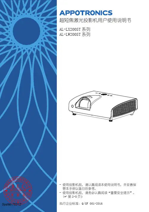
超短焦激光投影机用户使用说明书AL-LX200ST系列系列AL-LW200ST管本手册以备日后参考。
2017-09-08- 使用投影机前,请务必认真阅读“重要安全提示”。
( 第2-5页)执行企业标准:Q/GF 001-2016SysNo.763122重要安全说明♦ 请勿让任何液体溅落到投影机上。
♦ 在雷暴期间或者长期不使用时,为更 好保护投影机,请拔下电源插头。
这 可以防止雷电或电力线路电涌对设备 造成损坏。
本产品为B 级产品。
SysNo.763122017-09-083重要安全说明SysNo.763122017-09-084重要安全说明SysNo.763122017-09-085重要安全说明SysNo.763122017-09-086声明有限保修在正常使用和存放情况下,Appotronics 对本产品的任何材料和工艺缺陷提供保修,保修时必须提供购机日期证明。
如果在保修期内发现本产品有缺陷,Appotronics 唯一的义务和针对您的独家补救办法是更换任何有缺陷的部件(包括劳务费)。
当您购买的产品发现有缺陷时,应立即通知经销商,以获得保修服务。
重要事项:如果客户未按照 Appotronics 的书面用法说明使用本产品,将不适用上述保修。
尤其是环境湿度必须介于10% 和90%之间、温度介于0°C 和 40°C 之间,以及避免在多灰尘的环境下操作本投影机。
有关其他信息,请访问 。
版权所有深圳市光峰光电技术有限公司保留所有权利。
未经深圳市光峰光电技术有限公司事先书面许可,不得以任何形式或方式,包括电子、机械、磁性、光学、化学、手写或其它方式,对本文的任何部分进行复制、传输、转译、储存于检索系统或翻译成任何文字或电脑语言。
所有商标和注册商标均属其自各所有人所有。
免责声明深圳市光峰光电技术有限公司未对本手册中的任何内容作出任何明示或暗示的陈述或保证,尤其对适销性或针对特定用途的适用性不提供任何保证。
Installing the ultra short throw lensThe ultra short throw (UST) lens allows you to position your projector as close as possible to the screen.Affected productsThe following products are affected:•D13HD2-HS•D13WU2-HS•D16HD-HS•D16WU-HS•D20HD-HS•D20WU-HS•Christie 4K7-HS•Christie 4K10-HSRequired componentsThe following components are required.•UST lens bracket kit (P/N: 003-006916-XX)• 3 mm Allen key• 5 mm Allen key• 6 mm Allen key•Hexagon wrenchMounting the lens support bracketThe lens holders are replaceable parts marked with an A for the HS Series 2K models and T for the 4K7-HS and 4K10-HS models.1.Turn on the projector and perform a lens calibration.•If you have a non-ultra short throw lens (standard lens) installed, perform a lens calibration by selecting Menu > Configuration > Lens Settings > Lens Calibration.•If you do not have a non-ultra short throw lens, complete the following steps:a.Connect to the projector using RS232 or Ethernet (default IP address 192.168.0.100).b.Perform a lens calibration by sending the serial API command (LCB+HOME 1) to theprojector.2.Turn off the power to the projector.3.Remove the non-ultra-short throw lens, if installed.4.Before mounting the bracket, align the mark lines as shown below.8.Flip the projector over.9.Install the ultra short throw lens.10.Attach the lens bracket to the support base using the location hole (A) and pin (B).•For HS Series 2K, make sure to use the lens bracket marked with an A.•For 4K7-HS and 4K10-HS, make sure to use the lens bracket marked with a T.11.Lock the M4 x L10 screws (A for HS Series 2K and T for 4K7-HS and 4K10-HS) until tight andthen loosen the screws by one turn.12.Shift the lens bracket to fit the L-UST lens neck.Make sure the lens bracket plate (A) does not tilt with the lens holder (B).e two M4 x L10 screws to secure the lens fixture to the lens bracket.14.Tighten the two M4 x L10 screws from step 11.15.Tighten the two M4 x L22 screws from step 2.Adjusting the ultra short throw lens After mounting the lens support bracket, adjust the ultra short throw lens.1.Turn on power to the projector.2.Loosen by one turn the two M4 x L22 screws shown below.3.Perform a lens calibration.4.To adjust the image position, use the Lens Shift function.Do not use the Lens Shift function when the two M4 x L22 screws are locked.5.Tighten the two M4 x L22 screws from step 2.If the tilt of the lens is too significant to fine-tune, gently lift up the lens to reduce the image offset before locking the screws.6.Adjust the two M6 screws to fine-tune image position.7.To fine tune the lens roll angle, adjust the M6 screw using a hexagon wrench.8.Loosen by one turn the two M4 screws on the lens supporter, shown below.9.Adjust the boresight.For information on how to adjust boresight, refer to the product Installation and Setup guide.10.Tighten the two screws from step 8.11.To ensure the Lens Shift function cannot be executed after the boresight has been adjusted,from the on-screen display, navigate to Configuration > Lens setting > Lock all LensMotors and select Locked.Technical supportTechnical support for Christie products is available at:•North and South America: +1-800-221-8025 or ************************************•Europe, Middle East, and Africa: +44 (0) 1189 778111 or ********************************•Asia Pacific•Australia: +61 (0)7 3624 4888•China: +86 10 6561 0240•India: +91 (80) 6708 9999•Japan: 81-3-3599-7481•Singapore: +65 6877-8737•South Korea: +82 2 702 1601•Christie Professional Services: +1-800-550-3061 or ***********************。
400系列智能超短焦激光电视用户手册LV-MAX-400-LASER前言 .........................................................................................................产品简介 ................................................................................................产品规格参数 .........................................................................................包装概览 ..................................................................................................外观介绍...................................................................................................安装与调试 ...........................................................................................安装...........................................................................................................画面调整...................................................................................................操作指南.................................................................................................基本设置菜单 .........................................................................................系统主页 ..................................................................................................网络连接 ..................................................................................................应用安装和卸载 .....................................................................................声音配置 ..................................................................................................显示方式 ..................................................................................................图像配置 ..................................................................................................多屏互动 ..................................................................................................故障排除 ................................................................................................图像 ..........................................................................................................声音 ..........................................................................................................媒体播放和在线影视 .............................................................................其他.. (1)223488101313131414161617181919192020清洁..........................................................................................................清洁机身 ..................................................................................................清洁出光口 ..............................................................................................安全注意事项........................................................................................激光 ..........................................................................................................小心触电 ..................................................................................................防止人身伤害 .........................................................................................小心火灾 ..................................................................................................其他注意事项 .........................................................................................附录..........................................................................................................环保说明 ..................................................................................................回收说明 ..................................................................................................名词解释 ..................................................................................................声明 ..........................................................................................................2121212222232324242525262626主机×1台遥控器×1只(附7号电池1对)HDMI线×1根电源线×1根本机包装箱内含以下物品,请仔细核对下列物品是否齐全,如有缺失,请联系当地经销商。
INSTALLATION MANUAL English EditionD75X ULTRA SHORT SERIESSAFETY INSTRUCTION For your safety, please read the instruction before using the wall mount bracket. Any improper disposition caused by ignoring this manual may damage the hanger frame and result in personal injury and property damage. Please keep the manual properly for future reference. Please read the installation manual and safety instruction of the projector that matches our wall mount bracket and operate according to the instruction.SYMBOL INSTRUCTION In order to avoid personal injury and property damage, the following warning symbols are used in this setting manual. Please make sure that you have understood all these warning symbols while reading this instruction.SAFETY PROTECTION MEASURES FOR SETTING This instruction introduces how to use customized wall mounted bracket to install D75 ultra short throw projector on walls. The unit of measurement for all sizes mark place in this instruction is in “mm”.1 PACKAGING ITEMS P. 42 SPECIFICATIONS P. 53 PROJECTION DISTANCE CHART P. 74 INSTALLATION STEPS FOR WALL MOUNTED BRACKET P. 9(1):Dismantle parts(2):Verify the strength of walls, installation environment, installationposition and drill holes on the walls.(3):Install hanger frame on walls.(4):Verify the distance of the projector. Move the three axisfine-tuner to proper position according to the projector distancechart.(5):Power cord should pass through the hanger frame.(6):Adjust the slider plate up and down to align to the standard position.(7):Install the projector onto the hanger frame.(8):Connect the power cord and other electrical cables to theprojector.5 ADJUSTING STEPS OF PROJECTOR IMAGE P. 13(1) Switch on the projector(2) Adjust the aspect ratio(3) Display the test image(4) Adjust the left and right alignment position(5) Adjust the up and down rotation(6) Adjust the left and right rotation(7) Adjust the keystone(8) Adjust the image size(9) Adjust the image up and down(10) Switch off the testing image displayPART LIST Screen shot Hardware Specifications Qty Purpose3 (pcs)4 (pcs) D75X INSTALLATION (FRAME 1) SETTINGDRILLING PAPER (1:1)M4*10mm ball head cross head screw (with flat gasket and spring washer)M8*70mm setscrew (with nut, flat gasket and spring washer)Used for connecting wall mounted bracketstructure # 7 with projectorUsed for installing and fixing wall mountedbracket structure #1 onto the wall1:Please follow the instructions in the manual and install with the attached hardwares.2:Please prepare the required tools and hardwares before installationSPECIFICATION Item Spec Description RemarkAbout 4.72kg 30kg ±40mm P. 13±5°P. 14±5°±5°P. 15P. 16P. 17P. 18±40mm D75X INSTALLATION (FRAME 1) SETTING DRILLING PAPER (1:1)Gross mass of hanger frame The three axis fine-tuning components(2.82kg), wall fixturehardwares(0.86kg), independent components packed seperately (0.12kg).Not inclusive of wall mounted bracket’s weight.Frame structure # 3 adjustable by 30mm, frame structure # 7 adjustable by±10mm.The three axis fine-tuner does horizontal scrolling adjustment The three axis fine-tuner does horizontal rotating adjustment The three axis fine-tuner does vertical scrolling adjustment Maximum load capacity The left and right adjusting range The up and downrotation adjusting range The left and rightrotation adjusting range Keystone adjustingrange Forward and backward adjustment by range Up and downadjustment by rangeCan be adjusted120mm forwardSCREENSHOT OF PROJECT DISTANCE2.721D HSCREENPROJECT DISTANCE 929597D755WT WXGA 0.35()Screen size diagonal Screen width Screen height inch mm inch mm inch mm inch mm inch mm 908785233724132464228622102159778081767371198220462089193918741831485051474645123912791306121211711144Projecting distance (D)()Vertical distance H112.73323.313.4014.3815.0115.9816.65340.3365.3381.3405.8422.811.59321.511.8212.1612.3812.7212.95327.4336.1341.6350.2356.18285D751ST XGA 0.43()Screen size diagonal Screen width Screen height inch mm inch mm inch mm inch mm inch mm 80777520832159203219561905656763615916661727162615651524495148464512501295121911731143Projecting distance (D)()Vertical distance H113.83351.414.6215.7216.5117.61371.4399.4419.4447.412.88354.413.1813.6013.9014.32361.4372.6380.2390.968172754138240103611.16283.411.86328.578198761156646117514.62371.413.1836280203267172342107711.11282.311.02307.2100254085215453134617.55445.813.26364.1FRAME 7A:4-M8*70 SETSCREW STEP2SETTING DRILLING PAPEROF ULTRA SHORT SERIES(1:1) TO THE PROPERPOSITION IN UP SCREENFRAME 1 STEP3M:VERTICAL ROTATION ADJUSTMENT FIXING SCREW FRAME 2 STEP4FRAME 3 STEP5FRAME 4E:VERTICAL ROTATIONADJUSTMENT FIXINGNUTG:TRAPEZOID ADJUSTMENT NUTFRAME 6STEP6D:4-M4*10 PARALLELADJUSTMENT FIXINGSCREWB:4-M4*10 VERTICAL ROTATION ADJUSTMENT FIXING SCREW STEP4C:2-M4*10 PARALLEL ADJUSTMENT FIXING SCREW STEP5H:3-M4*10 BRACKET7 TIGHTEN SCREWI:3-M4*10 PROJECTORCONNECTION SCREWSTEP6F:PARALLEL ADJUSTMENTFIXING SCREWFRAME 5ASSEMBLY BREAKDOWN DIAGRAMROTATION ASIXQuick Installation Steps: Step 1: frame #1 setting drilling paper of ultra short series (1:1) to the proper position in up screen (see details please refer to P.9). Perforate the setting wall. (percussion drill and drill 8.5, 60mm depth) Step 2: Install M8*70 setscrew in the wall’s hole. Step 3: Use M8*70 setscrew (4X) fix structure frame # 1 to the wall’s hole. Step 4: Install structure frame # 2 on structure frame # 1 (see P.10), switch it to intermediate position and use screw B (M4*10 up and down adjusting fixing screw) to lock it yet. Step 5: Loosen screw “C”, decline structure frame # 3 by 5 degree to aim at the positioning peg, and position the slider structure into structure frame # 2’s slide-way. Adjust the slide-way tointermediate position and tighten the screw “C” into structure frame # 2 ‘s threaded hole, but do not lock it. When the positioning is in place, tighten the screw “C”. (see details please refer to P.11) Step 6: Use “I” screw to connect structure frame # 7 and projector. Fix them, and install them on structure frame # 6. After adjusting structure frame # 7 to a proper position, lock screw “H”. (see P.12)LWALIGN THE CENTRAL VERTICAL LINE ON THE SCREENSCREEN4-M8*70 SETSCREW M:VERTICAL ADJUSTMENT ROTATION SREWFRAME 1H 1SETTING DRILLING PAPER OFBRACKET 1 PROPER POSITIONALIGN THE CENTRAL VERTICALLINE ON THE SCREENWALL8.560SCREENSHOT 1INSTALLING STEP 1SCREENSHOT 2Installing steps of holder 1: 1: Ensure the projector image allies with the center line of the screen, and determine the corresponding vertical distance value (H1) according to the projector distance chart. 2: Use D79X setting perforating paper of ultra short throw series (1:1) to determine the corresponding vertical distance.(H2) = (H1)-27.2mm 3: Fix the D79X setting perforating paper of ultra short throw series (1:1) and drill the wall according to the hole position on paper.(see picture 1). 4: Drive the attached setscrew (4-M8*70mm) in the corresponding wall’s hole. 5: Loosen screw “B” (4-M4*10), and dismantle the setting wall components. (structure frame # 1 and structure frame # 2) 6: Install the structure frame # 1 and tighten the screw (see picture 2) to ensure that the installation is correct and reliable.Installing steps of structure frame # 2: 1: Place structure frame # 2’s neck into structure frame # 1’s up and down adjusting screwinserts. 2: Screw “B” screw (M4*10mm) into structure frame # 1’s corresponding threaded hole slightly.(2 PCS of both left and right side). 3: Use up and down adjusting screw to adjust structure frame # 2 to proper position, and tighten the screw“B”.(4-M4*10mm)AFTER INSTALLATIONInstalling steps of structure frame # 2:1: Loosen “C” screw. (2-M4*10mm)2: Decline the three axis fine-tuner by 5 degree to aim at the registration mast. As illustrated in the following picture 2, install the slide-way on structure frame # 2’s slide-way, and switch it to intermediate position.3: Tighten screw “C” (2-M4-10mm) into structure frame # 2’s corresponding threaded holeslightly, do not lock it.4: Adjust the screw “C” to proper position and tighten it. (2-M4*10mm)BEFORE INSTALLATIONC:2-M4*10 PARALLELAFTER INSTALLATIONInstalling steps of projector: 1: Loosen screw “H” (4X-M4*10), and remove structure frame # 7. 2: Use “I” screw (3-M4*10mm) to connect structure frame # 7 and projector, and assemble them together. 3: Assemble the connected structure frame # 7 and projector on structure frame # 6. 4: Tighten screw “H”(4-M4*10mm) into structure frame # 6’s corresponding threaded holeslightly, not locked. 5: Slide structure frame # 7 to proper position, and tighten screw “H”. (4-M4*10mm)Y XBZXB Instruction of up and down rotation movement: 1: Tuner “E” does clockwise movements and its function is to adjust structure frame # 6 to drive projector into clockwise (X axis direction) rotation adjustment.(picture A) 2: Tuner “E” does anti-clockwise movements and its function is to adjust structure frame # 6 to drive projector into anti-clockwise (X axis direction) rotation adjustment.(picture B) 3: The maximum adjustable angle is ±5 degree.Instruction of left and right rotation movement: 1: Screw “F” for and rotate axis nut slightly. 2: Take the rotation axis as the axis (Z axis), adjust the setting disc through horizontal left and right rotation so that structure frame # 7 can drive projector towards horizontal rotation.(Z axis direction). 3: When the horizontal rotation position is adjusted to a proper position, tighten the screw “F”. 4: When the three axis are adjusted to proper positions, tighten the rotation axis nut.Instruction of keystone adjustment movement: 1: Tuner “G” does clockwise movements and it’s function is to move structure frame # 6 to drive projector towards a clockwise (Y axis direction) rotation adjustment.(picture D) 2: Tuner “G” does anti-clockwise movements and it’s function is to move structure frame # 6 drive projector towards an anti-clockwise (Y axis direction) rotation adjustment.(picture C) 3: The maximum adjustable angle is ±5 degree.ZY XInstruction of image size adjustment movement:1: Loosen screw “D” (4-M4*10mm) slightly. Move structure frame # 5 forward and backward to adjust its position in Y axis.2: For the distance between screen and projector, please refer to the projector sheet.(P. 7) 3: When the image size is OK, please tighten screw “D”. (4-M4*10mm) 4: The maximum adjustable distance is 120mm.Instruction of image up and down adjustment movement: 1: Loosen screw “B” (4-M4*10mm) slightly. In order to adjust the image’s up and down position, turn “M” (up anddown adjustment rotation screw) to make sliding structure frame #2 up and down, so as to adjust the imageposition up and down (Z axis direction). 2: Please refer to the projector distance sheet.(P.7) for the highest position of screen to the projector’s up and down distance (H1). 3: When the image up and down position is well adjusted, tighten screw. “B” (4-M4*10mm) 4: The maximum adjustable distance is ±40mm.○ Vivitek ChinaNo. 1090 Century Avenue, Pudong New Area, Shanghai CIMIC building 18 F zip code 200120Tel: 86-21-58360088Fax: 86-21-58360099○ Vivitek EMEAZandsteen 152132MZ HoofddorpThe NetherlandsTel: +31 20 655 0960Fax : +31 20 655 0999E-mail:***************Web : www.vivitek.euD79X ultra short series installation instructions - 2nd Edition。
安装使用说明书中文简体D79X超短焦系列安全使用须知为保障您的安全,在使用吊架之前请先阅读本说明书的使用须知全文。
忽视本手册的使用须知而造成的处置不当,可能会损坏吊架,导致人身伤害或财产损失。
请将本手册妥善保管以备将来参考。
请阅读配合此吊架使用的投影机使用说明书和安全使用须知,并按照这些文档的说明进行操作。
符号说明为避免造成人身伤害或财产损失,在本安装手册中使用了下列警告标志。
请您务必在阅读本说明书时已了解这些警告的含义。
安装安全防护措施安装吊架的地点1:事先在安装吊架的位置进行电源布线工作。
2:安装投影机的位置应远离其它电气设备(如荧光灯或空调等),某些类型的荧光灯可能会干扰投影机的遥控器。
3:建议连接电缆的长度不超过20米,以减少外部噪音。
4:建议使用插入式屏幕或平板屏幕。
5:使用交互功能时,确保在以下条件下设置投影机。
(1):投影屏幕为矩形形状,无任何失真。
(2):投影机相对于投影屏幕,垂直和水平倾斜角度不超过±3°。
(3):使用梯形校正时,水平梯形校正和垂直梯形校正的量不超过±5°。
关于本安装说明书本说明书介绍如何使用专用的吊架将D791ST XGA 0.24/D795WT WXGA0.19,超短距投影机安装到墙壁上。
本说明书所有尺寸标注处,标注单位为:mm1 装箱物品P. 42 规格P. 53 投影距离表P. 74 安装步骤P. 9(1):分解部件。
(2):确认墙壁强度,安装环境,安装位置及在墙壁上打孔。
(3):在墙壁上安装吊架。
(4):确定投影距离,根据投影距离表移动三轴微调组件到恰当位置。
(5):使电缆穿过吊架。
(6):调整上下滑动,以对齐标准位置。
(7):将投影机固定到吊架上。
(8):将电源线和其它电缆线连接到投影机。
5 投影画面调整步骤P. 13(1):打开投影机。
(2):改变长宽比。
(3):显示测试图样。
(4):调整左右位置。
(5):调整上下旋转。
投影机安装之前的注意事项:1.确保室内安装投影机位置无漏水以及无脱落现象。
2.投影机安装位置有可供使用的220V交流电源,线路具备一定的承载能力。
3.确保投影机与投影机屏幕无太阳光直射,如果有太阳光直射,应做遮光处理。
4.投影机与电脑相连的vga视频线应短于30米。
如果超过30米,信号会有衰减,如果超出50米,可能无法检测到画面,如果vga视频线长度要求很长,可采用vga信号延长器,可使vga视频线变长,而不会有信号衰减严重的现象。
5.根据投影机镜头型号的不同,在相同的距离所投放出来的画面大小就会有所不同。
投影机安装方式:投影机的投影方式分为:正投安装、背投安装、吊顶安装。
任何一款投影机都可以根据安装需求调整投射方式,在菜单中可以看到有正投、背投、吊装等选项就是针对用户不同的安装方式或场地的限制而让客户灵活的安装投影机。
正投安装正投安装是投影机应用最为广泛的一种安装方式了,同时,这也是最易于实现的一种投影方式。
正投的概念就是指用户与投影机位于投射画面的同一侧,投影画面直接通过幕布或墙体反射到用户眼中的投影方式。
背投安装背投相对于正投,在画面效果方面会有一定的保障,由于用户从幕布上看到的是透射画面,加上这种投影方式本身都会对环境光做处理,因此可以说环境光对画面的影响很小,在投影质量方面要优于正投。
其次,由于是从投影幕后进行投射,因此用户的走动等也不会对投影画面造成影响。
背投的不足也是比较明显的,如占用空间大。
背投可以达到与正投一样的画面大小,但距离却几乎需要延长一倍,这一点对于很多空间狭小的场合而言就显得非常不便了。
目前最常见的解决方案是采用折射式背投法,也就是投影画面首先投射到已经设置好角度的镜子上,通过镜子的反射再将画面投射到幕布上,这种方式可以减小背投所需的距离。
吊顶安装吊顶安装需要投影机吊架吊顶安装需要投影机吊架,投影机吊架要用膨胀螺丝与顶面墙壁相连接。
使投影机吊架钉死、固定在顶面墙壁上。
CONNECTIVITY (May require optional accessories)Ultra Short Throw 1080p Entertainment ProjectorGT5600contrast ratio and 16-watt speaker impress by automatically optimizing the image for any surface with stunning visuals and crisp audio.USB display supersizes Android and iOS gaming by mirroring your experience via a single USB cable. HDCast Pro connectivity provides wireless screen mirroring with Android, Mac OS andWindows devices to easily broadcast your mobile gaming experiences for everyone to see.Four corner geometry correction allows flexible placement for projection onto virtually any surface while robust input options include HDMI, VGA and RJ-45. Up to 15,000 hours of lamp life ensures long-term reliability with minimal maintenance.Full 3D1080PUltra Short Throw 1080p Gaming Projector - GT5600OPTICAL/TECHNICAL SPECIFICATIONSDisplay TechnologyS ingle Texas Instruments 0.65” 1080p DMD Color Wheel 6-segment RGBWYC Native Resolution 1080p (1920 x 1080)Maximum Resolution WUXGA (1920 x 1200)Brightness 3,600 ANSI lumens Contrast Ratio 20,000:1Displayable Colors 1.07 billionLamp Life and Type* 15,000/10,000/4,000 (Dynamic/ECO/Bright) - 240W Projection Method Front, rear, ceiling mount, table top Keystone Correction Auto, ±4° horizontal/vertical Uniformity 80%Offset 118.8%± 3%Aspect Ratio 16:9 (native), 16:10 and 4:3 compatible Throw Ratio 0.25:1 (distance/width)Projection Distance 6”– 9”Image Size 80”– 100”Projection Lens F=2.4, 3.72mm manual focus Optical Zoom Fixed lensAudio 16WNoise Level 25dB (ECO)Remote Control Full function remoteOperating Temperature 41–104°F (5–40°C), 85% max humidity Power Supply Auto-ranging: 100V ~ 240V ± 10%, 50-60Hz Power Consumption 285W (Bright), 205W (ECO)High AltitudeOperating temperature at sea level up to 10,000 feet = 104° F (max); Must manually switch to high altitude mode from 5,000 feet and above (using OSD menu) to maintain optimal functionalityCOMPATIBILITY SPECIFICATIONSPC Free USB Media Player and Supports playback of audio files, viewing of office Office Document Viewer documents and PDF files via USB storage devices PC Free USB Media Player MP3, WMA, OGG, FLAC, APE, ATRA Audio Codecs and Containers PC Free USB Media Player JPEG, GIF, BMPImage FormatsPC Free Office Document and Word documents (.doc, .docx), Excel spreadsheets PDF Viewer Formats (.xls, .xlsx), PowerPoint presentations (.ppt, .pptx),Adobe Acrobat files (.pdf)Wireless Screen Mirror Screen mirroring for PC, Mac and Android using HDCastPro app (requires optional Wi-Fi adapter)Computer Compatibility SVGA, VGA, SXGA, UXGA, XGA,WXGA, HD, Mac Video Input Compatibility NTSC, PAL, SECAM, SDTV 480i/p, 576i/p, HDTV720p(50/60Hz), 1080i(50/60Hz), 1080P(50/60Hz)3D Compatibility † S upports all HDMI 1.4a mandatory 3D formats (Framepack, side-by-side, top-bottom) and up converts frame rate from 60Hz to 120Hz or 24Hz to 144Hz (i.e. 60 or 72 frames per eye). 3D glasses are sold separately. Please refer to user manual for details.Vertical Scan Rate 24 ~ 85 Hz (120Hz for 3D feature)Horizontal Scan Rate 15.375 ~ 91.146 KHzUser Controls Complete on-screen menu adjustment in 18 languages I/O Connection PortsHDMI 1.4a (MHL 2.0), HDMI 1.4a, composite video in, audio-in (3.5mm), VGA-in, VGA-out, audio-out (3.5mm), RS-232C, RJ-45, USB port (Wi-Fi adapter), USB port (USB display/PC-free/mouse/power)Loop Through (Audio)YesPHYSICAL SPECIFICATIONSSecurity Kensington® Lock Port, security bar and keypad lock Weight8.7 lbs.Dimensions (W x H x D)13.5” x 4.75” x 14.25”1-year parts and labor warranty, 90-days on the lampGT5600, AC power cord, remote control, batteries, USB Wi-Fi adapter, CD-ROM user’s manual, quick start guide and warranty card Universal wall mount, DLP Link™ 3D glasses, Wireless USB adapter, remote UST wall mount: OWM3000 DLP Link™ 3D glasses: ZD302Wireless adapter: WUSBCopyright © 2018 Optoma Technology, Inc. DLP ® and the DLP logo are registered trademarks of Texas Instruments ™. All other trademarks are the property of their respective owners. All specifications subject to change at any time. 08312018†3D content can be viewed with DLP Link active shutter 3D glasses when projector is used with a compatible 3D player. Please visit for more information.*Light source life is dependent upon many factors, including brightness mode, display mode, usage, environmental conditions and more. Light source brightness can decrease over time.167892345101112K-slotAudio-Out RS-232C AC Power HDMI-2/MHL HDMI-1Composite VGA-In VGA-Out RJ-45Audio-In USB 1. 2. 3. 4. 5.6.7. 8. 9.10.11.12.。