mt3dms_v5_supplemental
- 格式:pdf
- 大小:801.37 KB
- 文档页数:56


台湾欣技CipherLAB 1500CipherLab公司最新推出了性能显著的CipherLab 1500 手持式红光扫描器,专用于满足零/售、医疗保健和公共领域等市场的需求。
CipherLab 1500是一种符合人体工学的轻便产品,提供业界首例三向合一的脚架。
该机架是一种特殊的通用创新设计,使得CipherLab 1500可以安装在墙上,放置在桌面上,或用作自动感应扫描,是收款台、生产线或其它高使用率环境的理想选择。
解码速度超快的CipherLab 1500是CipherLab公司的高价值线性图像扫描器产品线中的最新成员,带来了通过工作人员效率与准确性的提高而实现的高投资回报、控制在最低限度的修理与维护需求。
它包含用于自定义扫描器配置的综合软件工具ScanMaster,此工具不加收费用。
功能特点:²200 次/秒的快速解码速度可以保证高生产效率²时尚的轻便设计可以最大限度减少重复移动造成的损伤²因不使用激光、无移动部件可减少维护工作量而产生的可靠性²支持所有广泛使用的条形码格式²满足全球各种主流EMC法规的要求◆产品参数格类型CCD扫描器光学传感器2500象素光源红色发光二极管(625 纳米)分辨率3mil景深0.5到35厘米/0.2到13.8英寸(取决于条形码分辨率)扫描角度俯仰度:±70° 倾斜度:±70°PCS最小30%解码率200次/秒背景光照射100,000lux自动识别模式是支持的条形码Codabar, Code 128, Code 39, Code 93, Italian and FrenchPharmacodes,Industrial 2 of 5, Interleave 2 of 5, Matrix 2 of 5, MSI,Plessey, RSS14, Telepen, UPC/EAN,等编程特性数据编辑、界面选择、符号组态语言支持美式英语和英式英语/法语/意大利语/比利时语/挪威语/瑞典语/西班牙语/葡萄牙语/德语外型重量145克/5.1盎斯颜色黑色开关接触开关電氣特性电压+5伏 10%能量消耗30毫安/170毫安/250毫安备用/扫描/最大值操作环境操作温度0℃to 50℃ / 32℉ to 122℉储藏温度-22℃to 60℃ / -4℉ to 140℉操作/储藏湿度不凝结10% to 90% / 5% to 95%抗震从1.5米(4.9英尺)高度多次撞击到混凝土面上防护等级IP30静电放电±8kV 接触±15 kV 气流EMC规范FCC / CE / C-tick / MIC / BSMI / IC配置设置选项包括以Windows授权为基础的CipherLab ScanMaster软件(包含),通过直接连接或印刷条形码配置。

How to add the WattsOn power monitor model in MT Alliance V5.XThe 023-0293 WattsOn-1200-MSCT1-100A (120kW) is available in version 5.2The 023-0330 WattsOn-1200-MSCT1-200A (220kW) is available in version 5.2.1 Under ELKOR manufacturerFirst copy the diagram file “Elkor WattsOn-1200.bmp” (see Wiring diagram on page 4) in the folder Alliance\Images\Sensor Models\Click Sensor Model in the configure menuClick AddFill the form as described belowThese setting are for the WattsOn-1200-MSCT1-100A used with 3 MSCT1 CTs. For the WattsOn-1200-MSCT1-200A put 220 instead of 120.Click OKIf needed you can define the Power Factor Sensor Model as belowClick AddOnce completed you won’t have to repeat this step again for this site.To drop the Real Power reading, zoom in the appropriate viewDrag and drop a sensor from the Component boxMake the appropriate selection (120kW or 220kW) and click OK.Click on the new button and configure the name, disable or configure the alarm limits and the sensor node inputTo drop the Power Factor reading, zoom in the appropriate viewDrag and drop a sensor from the Component boxMake the following selection and click OK.Click on the new button and configure the name, disable or configure the alarm limits and the sensor node inputUser defined sensors are not available for a plug-in.Wiring diagramIf the CTs are not facing the same current direction the Power signal won’t be accurate and the Diag LED may not detect the fault.The WattsOn can be configured in different ways using a laptop with the appropriate software connected to the MODBUS port. So make sure you are using the respectively the WattsOn-1200-MSCT1-100A or 200A especially customized for this purpose or the output signals won’t reflect the expected values.For more information for the WattsOn installation see the Elkor WattsOn manual.。

5.0” HDMI TFT ModulesNewhaven Display International2661 Galvin Court ▪ Elgin IL ▪ 60124Phone: 847.844.8795 Fax: 847.844.8796Sales:*************************** Technical Support:**************************U s e r G u i d ePart NumberingNHD - x.x - HDMI - N - xxxx - xxx1 2 3 4 5 61 Manufacturer –Newhaven Display2 Size (in inches)–5.0” Diagonal–7.0” Diagonal3 Interface –HDMI Interface4 Descriptor –800x480 Resolution, Video Only [HDMI audionot supported]5 Type –Premium MVA [Standard model for 7.0” size]–n/a [Only available in 7.0” size]–n/a [Only available in 7.0” size]6 Touch Panel–No Touch–Capacitive USB-HID [Pre-calibrated, No external drivers needed]–Resistive USB-HID [Pre-calibrated, No external drivers needed]Table of ContentsOverview (3)Functions and Features (3)Model Information (4)Electrical Characteristics (4)HDMI Receiver Information (4)Interface Description (4)Connecting with Windows/Windows Embedded (6)Connecting with Linux (8)Technical Resources (9)2D Drawings (9)3D Models (9)EDID Timing (9)Schematic (9)EDID Array (9)Quality Information (10)Precautions for Using LCDs/LCMs (10)Warranty Information (10)Document Revision History (11)OverviewThe HDMI interface has become the most popular video interface standard to date, and HDMI video sources are easier to come by now than ever before. Whether you need an HDMI TFT display for your Raspberry Pi/BeagleBone Black application, a Windows/Windows Embedded PC monitor, or a touch screen HMI for your Linux or other embedded system, the Newhaven Display HDMI TFT product line offers a solution.Our HDMI TFT Modules unite our existing high-quality TFT display panels with a custom PCB engineered in the USA by Newhaven Display. Assembled to the display, our PCB provides the user an all-in-one, plug-and-play HDMI + USB Touch solution for virtually any application.Functions and Features5.0” HDMI TFT Module w/ USB-HID Capacitive or Resistive Touch optionsOn-board Texas Instruments TFP401A HDMI/DVI ReceiverHDMI (Type-A) InputCompatible with PC (Windows/Linux)Compatible with Linux based SBCs such as Raspberry Pi, BeagleBone, etc.Plug-and-play USB-HID Touch, no external driver installation required24-bit True Color, 800x480 Resolution (WVGA)On-board Texas Instruments TPS61165 High Brightness LED Driver w/ PWM75° Viewing Angles all sides4 x 3.5mm Mounting Holes Enabling Standard M3 or #6-32 ScrewsOpen-Source Hardware, Engineered in Elgin, IL (USA)Model InformationHDMI Module P/N TFT Panel Used DisplayTypeLuminanceRatingOptimalViewingAngleTouchPanelNHD-5.0-HDMI-N-RTXL NHD-5.0-800480TF-ATXL# PremiumMVA500 cd/m² 75° all angles No TouchNHD-5.0-HDMI-N-RTXL-CTU NHD-5.0-800480TF-ATXL#-CTP PremiumMVA415 cd/m² 75° all anglesProjectedCapacitive(USB-HID)NHD-5.0-HDMI-N-RTXL-RTU NHD-5.0-800480TF-ATXL#-T PremiumMVA400 cd/m² 75° all angles4-WireResistive(USB-HID)For detailed information on the TFT Panel used, please view its Product Specification by accessing the product webpage link above. Electrical CharacteristicsItem Symbol Condition Min. Typical Max. Unit Operating Temperature Range T OP Absolute Max -20 - +70 ⁰C Storage Temperature Range T ST Absolute Max -30 - +80 ⁰C Backlight PWM Frequency f PWM - 5 - 100 kHz Module Supply Voltage V DD- 5.0 - 9.0 VModule Supply CurrentI DD V DD = 5V - 560 590 mA V DD = 9V - 420 450 mAHDMI Receiver InformationOn-board Texas Instruments TFP401A Receiver.To view the full TFP401A specification, please download it by accessing the link below: /lit/ds/slds190a/slds190a.pdfInterface Description(Capacitive Touch model shown above as reference)Num. Description1) (LED4)LED Indicator for Touch–Capacitive Touch models onlyThis is a Red LED that will illuminate when there is a touch sensed on the CTP.2) (LED2)LED Indicator for Touch–Resistive Touch models onlyThis is a Red LED that will blink slowly (once per second) if the RTP controller is powered ON, awake, and no touch isdetected. This LED will blink rapidly (5 times per second) if the RTP controller detects a touch.3) (CN4)Surface Mount Pin Header, 2.54mm pitch, for Backlight PWMThe pin labelled ‘PWM’ is connected directly to the LED driver’s CTRL pin (T.I. TPS61165). This is a multifunctional pin whi ch can be used for enable control, PWM, and digital dimming. A PWM frequency in the range of 5kHz – 100kHz must be used.4) (CN3)DC Jack (Center-Positive)This is used to supply power to the display module. A DC power supply in the range of 5V – 9V must be used.The output current rating of the DC power supply should be at least the maximum Supply Current (I DD) listed in the Electrical Characteristics section on the previous page.5) (LED3)LED Indicator for PowerThis is a Green LED that will illuminate when DC power is supplied to the module.6) (CN2)Micro-USB (Type-B) Connector for Touch–Touch Panel models onlyThis is to connect the Touch Panel of this module to a USB input to act as a USB-HID device.7) (LED1)LED Indicator for VideoThis is a Blue LED that will illuminate when there is an active video signal detected.8) (CN1)HDMI (Type-A) ConnectorThis is a full-size HDMI connector meant to connect the HDMI source signal (Video only) to this module.The on-board T.I. TFP401A HDMI/DVI Receiver does not scale video resolutions. Therefore, the output resolution of thesource must be 800x480 (WVGA). In most applications, this is automatically detected by the HDMI source.Connecting with Windows/Windows EmbeddedConnecting our HDMI TFT Modules to a Windows system is fully plug-and-play. Start by plugging in a DC power supply in the range of 5 - 9V, with at least 1A of output current. The green LED near the DC jack will illuminate when the board has power supplied to it. Next, connect the display to your system via HDMI cable. Due to the on-board EDID, the display will be detected automatically and the system’soutput resolution will set itself to 800x480.For Touch Panel models, once the display is connected to the system via USB, Windows willautomatically detect and install the necessary drivers.The above window is shown for the Capacitive Touch model. The Resistive Touch model will also install automatically, however it will be labelled ‘AR1100 HID-MOUSE’ instead of ‘Newhaven Display’.Once Windows has finished installing the drivers, the device will show as ‘Ready to use’.For reference, in Device Manager the USB-HID Touch device will show as below:Connecting with LinuxMost Linux applications with an HDMI source will also be fully plug-and-play, however when using our HDMI TFT Modules with the Raspberry Pi, the config.txt file on the Pi’s microSD card will need to beslightly modified by the user.The following highlighted lines need to be added in config.txt for proper display output:# For more options and information see# http://rpf.io/configtxt# Some settings may impact device functionality. See link above for details# uncomment if you get no picture on HDMI for a default "safe" mode#hdmi_safe=1# uncomment this if your display has a black border of unused pixels visible# and your display can output without overscan#disable_overscan=1# uncomment the following to adjust overscan. Use positive numbers if console# goes off screen, and negative if there is too much border#overscan_left=16#overscan_right=16#overscan_top=16#overscan_bottom=16# uncomment to force a console size. By default it will be display's size minus# overscan.#framebuffer_width=1280#framebuffer_height=720# uncomment if hdmi display is not detected and composite is being output#hdmi_force_hotplug=1# uncomment to force a specific HDMI mode (this will force VGA)#hdmi_group=1#hdmi_mode=1hdmi_group=2hdmi_mode=87hdmi_cvt=800 480 60 6 0 0 0# uncomment to force a HDMI mode rather than DVI. This can make audio work in# DMT (computer monitor) modes#hdmi_drive=2# uncomment to increase signal to HDMI, if you have interference, blanking, or# no display#config_hdmi_boost=4# uncomment for composite PAL#sdtv_mode=2#uncomment to overclock the arm. 700 MHz is the default.#arm_freq=800# Uncomment some or all of these to enable the optional hardware interfaces#dtparam=i2c_arm=on#dtparam=i2s=on#dtparam=spi=on# Uncomment this to enable the lirc-rpi module#dtoverlay=lirc-rpi# Additional overlays and parameters are documented /boot/overlays/README# Enable audio (loads snd_bcm2835)dtparam=audio=onTechnical Resources2D DrawingsEDID TimingNHD-5.0-HDMI-N-RTXL Array NHD-5.0-HDMI-N-RTXL-CTUNHD-5.0-HDMI-N-RTXL-RTU3D ModelsNHD-5.0-HDMI-N-xxxxNHD-5.0-HDMI-N-xxxx-CTUNHD-5.0-HDMI-N-xxxx-RTUSchematicNHD-5.0-HDMI-NEDID Arrayconst unsigned char NHD_HDMI5[] = {0x00, 0xFF, 0xFF, 0xFF, 0xFF, 0xFF, 0xFF, 0x00, 0x39, 0x04, 0x3B, 0x07, 0x00, 0x00, 0x00, 0x00,0x01, 0x11, 0x01, 0x03, 0x80, 0x0B, 0x07, 0x00, 0x0A, 0x00, 0x00, 0x00, 0x00, 0x00, 0x00, 0x00, 0x00, 0x00, 0x00, 0x00, 0x00, 0x00, 0x01, 0x01, 0x01, 0x01, 0x01, 0x01, 0x01, 0x01, 0x01, 0x01, 0x01, 0x01, 0x01, 0x01, 0x01, 0x01, 0x80, 0x0C, 0x20, 0x80, 0x30, 0xE0, 0x2D, 0x10, 0x28, 0x30, 0xD3, 0x00, 0x6C, 0x41, 0x00, 0x00, 0x00, 0x18, 0x00, 0x00, 0x00, 0xFC, 0x00, 0x4E, 0x48, 0x44, 0x2D, 0x35, 0x2E, 0x30, 0x20, 0x48, 0x44, 0x4D, 0x49, 0x0A, 0x00, 0x00, 0x00, 0x10, 0x00, 0x00, 0x00, 0x00, 0x00, 0x00, 0x00, 0x00, 0x00, 0x00, 0x00, 0x00, 0x00, 0x00, 0x00, 0x00, 0x00, 0x10, 0x00, 0x00, 0x00, 0x00, 0x00, 0x00, 0x00, 0x00, 0x00, 0x00, 0x00, 0x00, 0x00, 0x00, 0x00, 0x5A, 0x00, 0x00, 0x00, 0x00, 0x00, 0x00, 0x00, 0x00, 0x00, 0x00, 0x00, 0x00, 0x00, 0x00, 0x00, 0x00, 0x00, 0x00, 0x00, 0x00, 0x00, 0x00, 0x00, 0x00, 0x00, 0x00, 0x00, 0x00, 0x00, 0x00, 0x00, 0x00, 0x00, 0x00, 0x00, 0x00, 0x00, 0x00, 0x00, 0x00, 0x00, 0x00, 0x00, 0x00, 0x00, 0x00, 0x00, 0x00, 0x00, 0x00, 0x00, 0x00, 0x00, 0x00, 0x00, 0x00, 0x00, 0x00, 0x00, 0x00, 0x00, 0x00, 0x00, 0x00, 0x00, 0x00, 0x00, 0x00, 0x00, 0x00, 0x00, 0x00, 0x00, 0x00, 0x00, 0x00, 0x00, 0x00, 0x00, 0x00, 0x00, 0x00, 0x00, 0x00, 0x00, 0x00, 0x00, 0x00, 0x00, 0x00, 0x00, 0x00, 0x00, 0x00, 0x00, 0x00, 0x00, 0x00, 0x00, 0x00, 0x00, 0x00, 0x00, 0x00, 0x00, 0x00, 0x00, 0x00, 0x00, 0x00, 0x00, 0x00, 0x00, 0x00, 0x00, 0x00, 0x00, 0x00, 0x00, 0x00, 0x00, 0x00, 0x00, 0x00, 0x00, 0x00, 0x00, 0x00 };Quality InformationTest Item Content of Test Test Condition Note High Temperature storage Endurance test applying the high storage temperaturefor a long time.+80⁰C, 96hrs 2Low Temperature storage Endurance test applying the low storage temperaturefor a long time.-30⁰C, 96hrs 1,2High Temperature Operation Endurance test applying the electric stress (voltage ¤t) and the high thermal stress for a long time.+70⁰C, 96hrs 2Low Temperature Operation Endurance test applying the electric stress (voltage ¤t) and the low thermal stress for a long time.-20⁰C, 96hrs 1,2High Temperature / Humidity Operation Endurance test applying the electric stress (voltage ¤t) and the high thermal with high humidity stressfor a long time.+60⁰C, 90% RH, 96hrs 1,2Thermal Shock resistance Endurance test applying the electric stress (voltage ¤t) during a cycle of low and high thermal stress. -20⁰C, 30min -> 25⁰C, 5min -> 70⁰C, 30min = 1 cycle10 cyclesVibration test Endurance test applying vibration to simulatetransportation and use. 10-55Hz, 15mm amplitude.60 sec in each of 3 directionsX,Y,ZFor 15 minutes3Static electricity test Endurance test applying electric static discharge. VS=800V, RS=1.5kΩ, CS=100pFOne timeNote 1: No condensation to be observed.Note 2: Conducted after 4 hours of storage at 25⁰C, 0%RH.Note 3:Test performed on product itself, not inside a container.Precautions for Using LCDs/LCMsSee Precautions at /specs/precautions.pdfWarranty InformationSee Terms & Conditions at /index.php?main_page=termsDocument Revision HistoryRevision Date Comments1.0 1/4/2017 Initial Release[read caution below]SCHEMATIC/PART NUMBER:REVISION:SCHEMATIC/PART NUMBER:REVISION:SCHEMATIC/PART NUMBER:REVISION:。

MZDR0850三维旋转连续变倍视频显微系统使用说明书桂林市迈特光学仪器有限公司使用前请注意:1. 操作:(1) 本仪器是一种精密仪器,在操作或运输过程中要轻拿轻放,避免碰撞。
(2) 避免阳光直接暴晒、高温、灰尘和震动。
(3) 镜片表面不应留有污物和手指印,以免降低本仪器成像清晰度。
2. 清洁和保管(1) 清洁光学零件表面应用脱脂纱布或棉花轻轻擦拭,如有手指印和油污,应用70%乙醚和30%酒精混合液沾湿脱脂纱布或棉花后轻轻擦拭。
!由于酒精和乙醚是高度易燃的溶剂,必须小心使用,一定要离开明火和可能产生电弧的地方,如电子设备的开和关。
同时也要记住应在有良好通风的房间使用这些化学试剂。
(2) 不要用有机溶剂擦拭其它元件表面,可用中性的清洁剂擦拭。
(3) 不要试图拆卸本仪器,以免降低精度。
(4) 在不使用仪器时请用防尘罩将仪器盖好,存放在干燥、无灰尘的地方。
3. 供电网络应有良好的接地。
目录:1. 简介 (1)2. 仪器清单 (1)3. 技术参数 (1)4. 各部件名称 (3)5. 仪器的安装 (3)6. 操作 (4)7. 故障维修指南 (5)1.简介MZDR0850三维旋转连续变倍视频显微系统,采用先进的光学技术和精密机械电子技术,使人们观察微观世界的角度从单一的正面观察扩展到三维全方位多角度观察,极大地提高了观察样品的细节程度。
无需倾斜就能360°全方位、大景深观察样品各个侧面的实时高分辨率动态图像,具有强烈的立体感和层次感,并且可以改变镜头的旋转速度,观察到传统镜头无法显示的位置,例如PCB贴片元器件下方、金属孔内部、侧壁等。
广泛应用于SMT、PCB、BGA等表面贴装工业。
为适合观察不同的物体,底端光轴与水平方向夹角有45°(标准型)、30°、60°、15°四种规格,此夹角越大,景深越大。
2.仪器清单本仪器标准配置包括下列部件:序号部件名称数量备注1 主机 12 底座 13 载物台 14 控制电源箱 15 输入电源线 16 内六角扳手 1 安装调整用7 CCD摄像头、视频线、CCD电源 1 选购件3. 技术参数总放大倍率=光学放大倍率×数字放大倍率数字放大倍率=显示器的显示屏对角线尺寸/CCD摄像头靶面对角线尺寸CCD摄像头靶面对角线尺寸:1/3” CCD:6mm;1/2”CCD:8mm;2/3” CCD:11mm.例如:14”监视器配1/3”CCD摄像头的数字放大倍率=64.2514×=59.2717”监视器配1/3”CCD摄像头的数字放大倍率=64.2517×=71.97 (1). 光学性能参数:CCD接头光学放大倍率总放大倍率视场范围(mm) 工作距离(mm)观察角度(与水平方向)0.3X 0.169X~1.125X 9.9X~66.6X 21.3X28.4~3.2X4.270.5X(标准配置)0.28X~1.875X 16.65X~111X 12.9X17.1~1.92X2.561X 0.56X~3.75X 33.3X~222X 6.4X8.6~0.96X1.281.5X 0.84X~5.625X 49.95X~333X 4.3X5.7~0.64X0.8520 45°注:总放大倍率、视场范围是以1/3”CCD摄像头、14”监视器计算CCD接头光学放大倍率总放大倍率视场范围(mm) 工作距离(mm)观察角度(与水平方向)0.3X 0.169X~1.125X 9.9X~66.6X 21.3X28.4~3.2X4.270.5X(标准配置)0.28X~1.875X 16.65X~111X 12.9X17.1~1.92X2.561X 0.56X~3.75X 33.3X~222X 6.4X8.6~0.96X1.281.5X 0.84X~5.625X 49.95X~333X 4.3X5.7~0.64X0.8511 30°注:总放大倍率、视场范围是以1/3”CCD摄像头、14”监视器计算(2). 输入电压:AC90~264V ,50Hz/60Hz(3). 保险管规格:2A(4). 载物台移动范围:X 方向100mmY 方向86mmCCD 接头 光学放大倍率 总放大倍率 视场范围(mm)工作距离(mm)观察角度(与水平方向) 0.5X(标准配置)0.1875X ~1.25X 11.1X ~74X 19.2X25.6~2.88X3.841X 0.375X ~2.5X 22.2X ~148.2X 9.6X12.8~1.44X1.92 1.5X 0.5625X ~3.75X 33.3X ~222.3X 6.4X8.5~0.96X1.28 6560°注:总放大倍率、视场范围是以1/3” CCD 摄像头、14” 监视器计算CCD 接头光学放大倍率总放大倍率视场范围(mm)工作距离(mm)观察角度(与水平方向) 0.5X(标准配置)0.1875X ~1.25X 11.1X ~74X 19.2X25.6~2.88X3.841X 0.375X ~2.5X 22.2X ~148.2X 9.6X12.8~1.44X1.92 1.5X 0.5625X ~3.75X 33.3X ~222.3X 6.4X8.5~0.96X1.28 815°注:总放大倍率、视场范围是以1/3” CCD 摄像头、14” 监视器计算4. 各部件名称5. 仪器的安装仪器的安装请看图1、图2a. 物镜主体与支架连接(图2)将托圈12从物镜主体9上旋下后,让主机自下往上从支架7中穿过,再将托圈12旋紧并拧紧止紧螺钉6。

Eaton Electric Limited,Great Marlings, Butterfield, LutonBeds, LU2 8DL, UK.Tel: + 44 (0)1582 723633 Fax: + 44 (0)1582 422283E-mail:********************© 2017 Eaton All Rights Reserved Publication No. EPS 901-107 Rev U January 20171The SD range is a series of surge protection devices combine unparalleled packing densities, application versatility, proven reliable hybrid circuitry, simple installation and optional ‘loop disconnect’ facilities – features which make the range the ultimate surge protection solution for process equipment, I/O systems and communications networks.The exceptionally high packing densities are the consequence of an ultra slim ‘footprint’ for individual modules which can thus ‘double-up’ as feedback terminals. Each module provides full hybrid surge protection for 2 and 3 wire loop protection.Modules with a comprehensive range of voltage ratings cover all process related signals such as RTDs, THCs, 4 to 20mA loops, telemetry outstations, shut-down systems and fire and gas detectors.Optional ‘loop disconnect’, is a feature which allowscommissioning and maintenance to be carried out without removal of the surge protection device. This facility is provided by the SD07, SD16, SD32 and SD55 units. In addition, a third connection on the field and safe side of the protector is provided in order to terminate screens safely.protecting electronic equipment and systems against surges on signal and I/O cabling.For three wire applications the specially designed SDRTD (Resistance Temperature Detector) and the SD32T3, (for separately powered 4-20mA loops) provide full 3-wire protection in a single compact unit. The recommended choice for the protection of 3-wire pressure transducers on low power circuits is the SD07R3.For higher bandwidth applications , the SDR range has been developed to meet the demands of today’s highest speed communication systems.120V and 240V AC versions are available for I/O and power supplies up to three Amps of load current and telephone networks can be protected by the SDPSTN.One simple manual operation clamps modules securely onto DIN rail, which automatically provides the essential high-integrity earth connection.‘T op-hat’ (T -section) DIN rail is generally suitable for mounting SD modules although for adverse environments, a specially-plated version is available. A comprehensive range of mounting and earthing accessories can also be supplied, see page 7 for further details.• Range of ATEX Certified intrinsicallysafe surge protectors• Ultra-slim space-saving design;easy installation• Multistage hybrid protection circuitry – 20kAmaximum surge current• Range of voltage ratings – to suit allprocess I/O applications• High bandwidth, low resistance, RTD, PSTNand 3-wire transmitter versions available• 10 year product warranty2from protected circuitry without needing additional disconnect terminals. The standard fuse (which is replaceable) is rated 250mA with 50mA fuses also being available by special request. Where only the disconnect feature is required, solid links can be used.As an example, this feature is of particular value in applications in which an SPD is used with a bulk power supply feeding disconnect terminals. The following guide to selection suggests the most suitable SDs for a number of specific applications. For technical information, see the detailed specifications on the back page of this publication (some field circuit protection is shown for completeness).FIELD CIRCUIT PROTECTED CIRCUIT 2-wire transmitters 3-wire RTDs Photocells, THCs,mV sources andturbine flowmetersAnalogue inputs (high-level)2-wire transmitters, 4-20mA, conventionaland smartThe SPDs recommended for use with ‘conventional’ and ‘smart’ 4-20mA transmitters (fed by a well-regulated supply) are the SD32 and SD55, the choice depending upon the maximum working voltage of the system (32V and 55V respectively). The diagram illustrates a prime example of an application for which the fuse/disconnect facility is particularly useful, however, both models are available in ‘X’ versions without the optional fuse/disconnect feature.Analogue inputs (low-level)RTDsThese applications are best served using the SDRTD. For optimum accuracy, the energising current should be chosen to ensure the voltage across the RTD does not exceed 1V over the full measurement range. When using a PT100 device, we recommend an energising current of 1mA.Photocells, THCs, mV sources and turbineflowmetersThe SD07 or SD16 (depending upon the operational voltage) are the favoured choices for this application. SD07X and SD16X are also suitable. 3Controller outputs (I/P converters)Switches Alarms, LEDs, solenoid values, etc.T elecom line PLC, I/O systemsController outputs (I/P converters)For this application, the recommendations are the SD16, SD32 and SD55 (and the equivalent ‘X’ versions), the final choice depending upon the operating voltage.Digital (on/off) inputsSwitchesSuitable SPDs for switches include the SD07, SD16, SD32 and SD55 modules – the choice depending upon the operating voltage of the system. T he ‘X’ versions of these are also suitable.Digital (on/off) outputsAlarms, LEDs,solenoid valves, etcAlarms, LEDs, solenoid valves, etcThe recommended choice for this application is the SD32 or SD32X.T elemetry (PSTN)Telemetry outstationsThe SDPSTN has been designed specifically for the protection of signals transmitted on public switched telephone networks.AC supplied equipmentPLC, I/O systemsFor systems on 110-120V ac, the SD150X is the recommended choice and for 220-240V ac systems, the SD275X is recommended.cable entries. Where these entries are not available or 3-wire devices are used, the compact design and simple installation of the SD range makes it the obvious choice for transmitter protection.The SDs within the junction box should be installed no further than one metre away but as close as possible to the sensor or made by fixing the metallic transmitter housing to the plant structure. This bond ensures the voltage difference between the signal conductors and the transmitter housing is below the transmitter’s insulation rating. Please note that the transmitters or sensors are connected to the ‘Protected Equipment’ terminals of the SD and not the ‘Field Cables’.2-wire transmitter or sensor 3-wire transmitter or sensor 4-wire transmitter or sensor TO HOST CIRCUITSD PROTECTED FIELD CIRCUIT 2-wire transmitters or sensors4-20mA transmitters, conventional and smartWhere the TP48 is not an acceptable solution,either because of technical suitability ordifficulties in mounting, the SD16X, SD32Xand SD55X are an excellent alternative.3-wire transmitters or sensorsVibration Sensors and 4-20mA loop processcontrol systems invariably require threewire connections, when powered from anexternal source.This may be accomplished in one unit byusing the SD32T3 three terminal SurgeProtection Device (SPD).Because the SD32T3 protects all threeconductors within the same unit, higherprotection is achieved, as the SPD hybridcircuitry is common to all three wires.The SD07R3 is available for the protection of3-wire pressure transducers on low powercircuits.4-wire transmitters or sensorsFlow meters, level detectors, etc.4-wire systems such as level detectors requiretwo SDs, one for the supply and the otherfor the transmitter output. Generally thevoltages across the pairs are similar and sothe recommended choice would be a pair ofSD16X, SD32X or SD55Xs. However, mainspowered transmitters should be protectedwith an SD150X or 275X (depending uponsupply voltage) for the supply inputs.Loadcells are catered for by MTL SurgeTechnologies’ LC30 which is suitable for both4- and 6-wire load cells.4 5TP PROTECTED FIELD CIRCUIT SD PROTECTED HOST CIRCUIT RS232, RS422, RS485SD PROTECTED HOST CIRCUIT PROTECTED FIELD CIRCUIT Bus powered systems Communication systems RS232, RS422, RS485The recommended choice for these applications is the SD16R or SD32R depending on the maximum driver signal.Bus powered systems There are a variety of bus powered systems specially designed for the process industry. The ideal surge protection device for these systems is the SD32R as it has a very high bandwidth and a modest in-line resistance.T ypical Applications Table 1 shows suitable SD devices for different applications. In some applications alternative devices may be used, for example, where lower in-line resistance or a higher voltage power supply is used.MTL Surge Technologies has operationally tested the recommended SD range with representative highways listed but no formal approval for their use in systems by therespective bodies has been sought.T able 1 6P i = 1.2W (–30°C to +60°C)P i = 1.3W (–30°C to +40°C)The SD** range is classified as simple apparatus and are intended for use in Zone 2 or safe areas only, because their fuses are not fully encapsulated.Installation Positioning The SDs should be mounted on the field wiring side to ensure that any surges entering from the field do not damage any intrinsically safe barriers or galvanic isolators in the system. The SDs and IS interfaces should be mounted close to each other but on separate DIN rails in order to maintain the required 50mm clearance between safe area and hazardous area terminals.Earthing The recommended earthing for field mounted devices has been illustrated pre-viously but it is the earthing at the control panel that is more critical as there are usually a number of earthing systems, each with their own requirements. The earthing system illustrated here replaces the instrument 0V bond, the control system PSU bond and the IS earth with one single earth connection to meet all the design requirements and give the most effective protection against the effects oflightning induced surges.(1996-12) Electrical apparatus for explosive gas atmospheres Part 14: Electrical installations in hazardous areas (other than mines) stresses the importance of SPDs in hazardous areas. An outdoor installation, where there is a high likelihood of both lightning induced transients and combustible gases, requires the installation of SPDs to prevent possible ignition of the gases. Areas seen particularly at risk include flammable liquid storage tanks, effluent treatment plants, distillation columns in petrochemical works and gas pipelines.SPDs for transmitter protection should be installed in Zone 1 but sufficiently close to the Zone 0 boundary to prevent high voltages entering Zone 0. The distance from the SPD to Zone 0 should be less than one metre where possible. However, in practice the SPD would normally be mounted on the transmitter or sensor housing which usually lies in Zone 1 and is very close to Zone 0. Because there is only a very small free volume, the SD range is suitable for mounting in flameproof or explosion proof enclosures.Zone 2The SD range is suitable for protecting electrical circuits in Division 2, Zone 2 and can be used without affecting the safety aspects of the circuit. Non-incendive (low-current) circuits can be protected using any SD range unit mounted in either the safe or hazardous area including those with the fuse disconnect facility. Non arcing (high current) circuits can also be protected except that SPDs with the fuse disconnect facility may only be mounted in the safe area. For use in these circuits the units must be mounted in a suitable enclosure, normally the minimum requirements are IP54 and 7Nm resistance to impact. The SD range is self-certified by MTL Surge Technologies as being suitable for this purpose.Certification Introducing surge protection into Intrinsically Safe (IS) circuits is trouble free as long as the current and power parameters are not exceeded. In the SD range, the SD**X, SD**R, SD**R3, SDRTD and SD**T3 all have ATEX certification for use in IS circuits located in Zones 0, 1 or 2. The certification parameters for the SD**X and SD**T3 are:Ex ia IIC T4 Ga, Li = 0.22mH I i = 260mA for Ui up to 20V I i = 175mA for Ui up to 26V I i = 140mA for Ui up to 28V I i = 65mA for Ui up to 60VThe certification parameters for the SD**R, SD**R3 and SDRTD are:Ex ia IIC T4 Ga, Li = 0I i = 260mA for Ui up to 60V7practice. These are placed at regular intervals along the rail or at each end as required. Earth connections can be made to the DIN rail via the earth terminal (ETL7000). Weatherproof enclosures are also available with all the necessary mounting accessories to install the SD range of surge protection devices.on the tops of individual SPDs. Both methods can be used conjointly. Replaceable fuses or solid links are available in packsof 5 (SD-F25, SD-F05 and SD-LNK).DIMENSIONSMounting accessories ISP7000 Insulating spacer THR2 Standard DIN rail, 35mm x 7.5mm THR7000 T -section DIN rail, specially nickel plated, 35mm x 7.5mm, 1m lengthEarthing/earth rail accessories ETL7000 Earth terminal, DIN rail mounted IMB57 Insulated mounting block (two needed)ERB57S Earth rail bracket, straight ERB57O Earth rail bracket, offset ERL7 Earth rail, 1m length ETM7 Earth terminal, pack of 50T agging accessories TAG57 Tagging strip, 1m length TGL57 Tagging strip labels, set of 10 x 0.5m BRI7000 Barrier identifier BIL7000 Barrier identification labels, sheet of 120BIL7000L Barrier identification labels, A4 sheet of 126Enclosures DX070 Enclosure for up to 9 x SD range SPDs DX170 Enclosure for up to 22 x SD range SPDs DX430 Enclosure for up to 58 x SD range SPDs Accessories (replacement)SD-F25 Replaceable fuse pack - 250mA standard (available in packs of 5)RLA7050 Replaceable fuse pack - 50mA special (available in packs of 5)RLA7000 Solid Link (available in packs of 5)SIL informationThe user of the SD range can utilize these failure rates in a probabilistic model of a safety instrumented function (SIF) to determine the suitability in part for safety instrumented system (SIS) usage in a particular safety integrity level. A full table of failure rates in presented in the EXIDA report (section 4.4) along with all assumptions.*The Residual Effect failures are included in the Safe Undetected failure category according to IEC 61508. Note that these failures alone will not affect system reliability or safety and should therefore not be included in spurious trip calculations.Safe Failure Fraction needs to be calculated on (sub)system level.A complete copy of the EXIDA report can be downloaded at .EUROPE (EMEA): +44 (0)1582 723633 ********************THE AMERICAS: +1 800 835 7075 *********************ASIA-PACIFIC: +65 6 645 9888***********************The given data is only intended as a product description and should not be regarded as a legal warranty of properties or guarantee. In the interest of further technical developments, we reserve the right to make design changes.Eaton Electric Limited,Great Marlings, Butterfield, LutonBeds, LU2 8DL, UK.Tel: + 44 (0)1582 723633 Fax: + 44 (0)1582 422283E-mail:********************© 2017 Eaton All Rights Reserved Publication No. EPS 901-107 Rev U 230117January 20178Note : all figures are typical at +25°C unless otherwise stated; *standard fuse; +over full working temperature range; †at 20mA with a 250mA standard fuse; ‡these units need external 3A fuses; ^Signal; **Power & Common; <maximum energizing current depends upon RTD resistance. See page 2 for details.Max discharge surge current (I max ) (8/20µs)20kA (8/20µs)6.5kA (SD150X and SD275X only)Nominal discharge surge current (i sn )3kA (8/20µs)Lightning impulse current (I imp ) (10/350µs)2.8kA 1.0kA (SD150X and SD275X only)Response time <1ns RTD resistance range (SDRTD)10 to 1500 Degradation accuracy (SDRTD at 1mA)0.1% (RTD resistance > 100 )0.1W (RTD resistance < 100 )Ambient temperature –40°C to +80°C / -40°F to 176°F storage –40°C to +80°C / -40°F to 176°F working For IS working applications:P i = 1.0W (–30°C to +75°C / -22°F to 167°F)P i = 1.2W (–30°C to +60°C / -22°F to 140°F)P i = 1.3W (–30°C to +40°C / -22°F to 104°F)Humidity 5 to 95% RH (non-condensing)Category tested A2, B2, C1, C2, C3Overstressed fault mode in=3kA 12kA 9kA (SD150X and SD275X only)Impulse durability (8/20µs)10kA 6.5kA (SD150X and SD275X only)Terminals 2.5mm 2 (12 AWG)Mounting T-section DIN-rail 35 x 7.5 or 35 x 15mm rail (1.38” x 0.3” x 0.6”)Weight 70g approximately (2.5oz)Case flammability UL94 V-2AC durability 1A rms , 5T Service conditions 80kPa - 160kPa 5% - 95% RHEMC compliance To Generic Immunity Standards, EN 61326-1, part 2 for industrial environmentsR&TTE compliance EN 61326-1, EN 41003 : 1999EN 60950 - 1 : 2006(not applicable to SD150X and SD275X)LVD compliance SD150X & SD275X EN 60950 - 1 : 2006, EN 61010 : 2010SDPST EN 41003 : 1999IEC compliance EN 61643-21:2001ANSI/IEEE testing C62.41-1-2002C62.41-2-2002C62.45-2002T o order - Order by module, as listed in the specification table and/or accessory part numbers, as defined on page 7.Products highlighted in blue are ATEX certified Ex ia IIC T 4 Ga.Approvals Authority (Country)Standard Certificate/File No.Approved for Product Baseefa [ATEX](EU)EN 60079-0:2009EN 60079-11:2007Baseefa02ATEX0211X Ex ia IIC T 4 Ga Ta = -30°C to See Schedule SD07X, SD16X, SD32X, SD55X,SD07R, SD16R, SD32R, SD55R,SDRTD, SD32T3, SD07R3, SD16R3, SD32R3, SD55R3Eaton (EU)EN 60079-15:2005EN 60079-14:2003MTL03ATEX0755X Ex nA IIC T 4SD07, SD16, SD32, SD55, SD07X, SD16X, SD32X, SD55X, SD07R, SD16R, SD32R, SD55R, SD32T3, SD07R3, SD16R3, SD32R3, SD55R3, SDRTD Baseefa [IECEx](International)IEC 60079-0: 2007-10IEC 60079-11: 2006IECEx BAS 12.0003X Ex ia IIC T 4 Ga SD07X, SD16X, SD32X, SD55X, SD07R, SD16R, SD32R, SD55R, SDRTD, SD32T3, SD07R3, SD16R3, SD32R3, SD55R3CSA/C/US (Canada, USA)CSA C22.2 No. 0-M1991CSA C22.2 No. 157-M1992UL 913, 5th edition CSA C22.2 No. 142-M1987CSA C22.2 No. 213-M1987LR 36637EEx ia Class 1,Groups A, B C and D, T 4Class 1, Div 2Groups A,B,C, D T 4SD07, SD16, SD32, SD55, SD07X, SD16X, SD32X, SD55X, SD07R, SD16R, SD32R, SD55R, SDRTD, SD32T3, SD07R3, SD16R3, SD32R3, SD55R3 UL (USA)UL 497B Listed E220693Isolated loop communication circuits SD07, SD16, SD32, SD55, SD07X,SD16X, SD32X, SD55X, SD07R,SD16R, SD32R, SD55R, SD07R3, SD16R3, SD32R3, SD55R3, SD32T3, SD55T3, SD07X3, SD16X3, SD32X3, SD55X3, SDRTDAustel (Australia)AS/NZ3548:1995AS/NZS4117:1996TS001: 1997__Private WireSD07R。
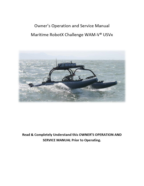
Owner’s Operation and Service ManualMaritime RobotX Challenge WAM-V® USVxRead & Completely Understand this OWNER’S OPERATION AND SERVICE MANUAL Prior to Operating.Table of ContentsSafety Precautions (3)Included With Your Vessel (4)Design Specifications and Construction (5)Major Dimensions and Payload Requirements: (5)Sub Assembly Specifications and Construction (6)Assembly Procedure: (8)Hull Inflation (8)Assembly Steps (10)Disassembly (17)Hinge System and Propulsion Interface (18)Suspension System and Payloads (23)Setting Your Spring Pressure (23)Setting Your Damping Rate (25)Pre-Launch Checklist: (26)Vessel Launching (27)Trailer Launching (27)Side Davit/Hoist Launching (27)Towing: (29)Periodic Maintenance: (30)Inflatable Hull Care, Maintenance & Repair (32)Packing For Shipment (33)Vendors: Component Specifications and Manuals (40)Cane Creek: (40)SKS: (40)Gommorizzo: (40)Safety PrecautionsThis vessel is designed for a maximum payload capacity of 300 lbs (136 kg).DO NOT EXCEED.The inflatable hulls should be inflated to a pressure of 2.0 – 2.2 psi (140 – 150 millibar). Maximum pressure rating is 3.0 psi (205 millibar), DO NOTEXCEED.After operation, deflate both hulls to 1.0 psi (70 millibar) to avoid over pressurization and internal baffle rupture due to temperature changes.CRITICAL: Inspect all push button quick release pins to ensure that the spring loaded retaining ball is functioning properly. Replace immediately if there is any sign of damage or if the internal spring mechanism is notfunctioning properly. Failure to do so may result in catastrophic damage or loss of the vessel.Hoisting: Always lift RobotX WAM-V USVx by securely attaching to all 4 payload tray lift points using hardware and slings that are appropriatelyrated for the load being lifted. See “Side Davit/Hoist Launching” section of this manual for the location of the hoist points on the payload tray. Do not walk beneath the vessel during lifting. Improper use of hoisting hardware, slings, or lift points may result in injury or death.The payload tray has attachment points for securing payloads. Please make sure payloads are always secured prior to operation.Included With Your VesselThe following spare parts and tools are included with your RobotX WAM-V USVx.2 x ¼” diameter, 1.5” long stainless steel quick release locking pin1 x ¼” diameter, 4.0” long stainless steel quick release locking pin1 x ¼” diameter, 1.75” long stainless steel quick release locking pin, with lanyard attached1 x 3/8” diameter, 3.0” long stainless steel quick release locking pin8 x retaining rings for ½” shaft size8 x ¼”-20 set screws w/ nylon patch4 x 8-32 set screws w/ nylon patch1 x wrench set: 3/8” – 1”1 x allen key set w/ vinyl pouch: 11 piece, 0.05” – 3/8”1 x double open ended wrench, 7/16” – 9/16”1 x double open ended wrence, 7/16” – ½”1 x T27 torx drive bit4 x 2500 lb load rated lifting sling, 3’ length6 x 1 ton lifting shackle, 3/8” screw pin1 x 3300 lb load rated high depth shackle1 x West Marine hand operated inflator pump1 x SKS SAM suspension pump2 x replacement fill valves for hypalon hulls1 x Cane Creek DBair shock absorber w/ adjustment tool [shipped separately]2 x Cane Creek DBair shock absorber valve cap w/o-ring [shipped separately]2 x IGUS KSTM-30 pillowblock bearing [shipped separately]1 x IGUS KSTM-GT35 pillowblock bearing [shipped separately]Design Specifications and Construction Major Dimensions and Payload Requirements: Beam: 96” (244 cm) [outside to outside]Overall Hull Length: 154” (391 cm)Ski Length: 112” (284 cm)Hull Diameter: 16.75” (42.6 cm)Payload: 300 lbs. (136 kg) maximumFull Load Displacement: 560 lbs. (255 kg) (estimated)Draft: 6.5” (16.5 cm) (estimated)Primary drawing dimensions in inchesPrimary drawing dimensions in inchesSub Assembly Specifications and Construction1.Payload TrayMaterial and Construction: Riveted tube frame and stress skin construction using 5086 and 6061-T6 series aluminum components anodized to MIL-A-8625 Type III. Rear Arch and Front Arch Assembly bearing surfaces are Delrin and reinforced nylon respectively.Weight: 54.5 lbs (24.7 kg).Primary drawing dimensions in inches2.Rear ArchMaterial and Construction: CNC bent tube construction using 6061-T6 series extruded and machined aluminum components anodized to MIL-A-8625 Type III. Inserts and reinforcements riveted in place.Weight: 33.5 lbs (15.2 kg).3.Front ArchMaterial and Construction: CNC bent tube construction using 6061-T6 series extruded and machined aluminum components anodized to MIL-A-8625 Type III. Inserts and reinforcements riveted in place.Weight: 11 lbs (5.0 kg).4.SuspensionMaterial and Construction: Structurally riveted construction consisting of water-jet cut 6061-T6 aluminum plate and extruded sections. CNC machined mounting brackets for all suspension component attachments. All components anodized to MIL-A-8625 Type III. Shock absorbers provided by Cane Creek feature integrated air spring and damper combination with all stainless steel and anodized aluminum construction. Custom valving optimized for WAM-V suspension dynamics featuring external adjustability of spring and damping rates via Schrader valve and barrel adjusters respectively.Weight: 16.5 lbs (7.5 kg). (each)5.SkiMaterial and Construction: Custom 6061-T6 series aluminum extrusion with water-jet cut and CNC machined mounting brackets and reinforcements. Ski-Can is constructed of rolled and welded 0.080” (2 mm) Aluminum 6061-T6 sheet. Can is attached to Ski extrusion via water-jet cut and bent 5086 Aluminum brackets and structural rivets. All components anodized to MIL-A-8625 Type III.Weight: 42.5 lbs (19.3). (each)6.HullMaterial and Construction: Hypalon/polyester (Orca 866 manufactured by Pellel & Flipo).Weight: 20 lbs (9 kg). (each)Assembly Procedure:Hull InflationThe RobotX WAM-V USVx is equipped with hypalon fabric hulls mounted to a rigid aluminum ski. Your RobotX WAM-V USVx was shipped with hull valves locked open. Hull valves must be unlocked before inflation. To unlock the valves, depress and rotate the green button clockwise until green button extends fully. The hulls must be inflated before assembly. Each hull contains a central baffle separating two independent inflation chambers. To inflate, remove the valve cover by rotating the cover counterclockwise.Insert the hand pump valve and rotate clockwise to lock and seal the pump to the hull valve.Inflate each chamber to 2.0 – 2.2 psi (140 – 150 millibar). Replace valve covers by inserting cover and rotating clockwise until locked. In the event of over inflation, depress the green valve release button until desired pressure is reached.To deflate fully, depress the green release button and rotate clockwise until release valve is locked in the open position. After deflation, rotate green release button counterclockwise to close valve.Assembly Steps1. Clear an 8’ x 14’ (2.4 m x 4.3 m) space on the ground (or trailer) and lay out both hulls roughly80” (2 m) apart (centerline to centerline).2.Remove both foot pins by retracting the ¼” (6.3 mm) locking pin and pulling the pin free fromthe foot clevis. Set foot pin aside.3. Set both rear arch foam wedges over the aft most handle on the top of each ski. Line eachwedge up with the inboard edge of each ski.4. Carefully insert the base of the rear arch into the each foot clevis until the pin hole is aligned.Insert foot pin through both ends of the clevis and lock by inserting the ¼” (6.3 mm) locking pin vertically into the locking side of the foot clevis.5.IMPORTANT: Lay the rear arches back until they are resting on the rear arch foam wedgesinstalled in step 3. Failure to do so will result in damage to the rear arch and/or foot assemblies.6. While holding the front arch in between the forward portion of the hulls, slide the front archclevis over the forward balljoint of the suspension assembly and insert 3/8” (9.5 mm) locking pin.7. Repeat this procedure (6) for the opposite hull, laying the front arch forward after both pins arein place.8.Lift the payload tray in between the two arches. Insert the front balljoint shaft into thepillowblock balljoint mounted in the center of the front arch. Place the balljoint shaft cap on the front of the shaft, and secure with the ¼” (6.3 mm) retaining pin attached to the payload tray by inserting the retaining pin vertically through both the shaft and shaft cap.9.Lift the aft end of the payload tray until it is roughly level with the ground. While holding thetray, rotate the rear arch into place. Secure each arch tube in the C-shaped arch mounts.10.Rotate the plastic clamp so that it makes contact with the inside walls of each arch tube. Insertthe ¼” (6.3 mm) locking pin into the pin guide hole at the aft-most arch mounts, locking the clamp in place.11.Remove and store the rear arch foam wedges.DisassemblyDisassembly of the RobotX WAM-V USVx is conducted in the reverse order from the Assembly procedure. For step by step directions, follow the procedure laid out in the “Assembly Procedure” portion of this manual in reverse.Hinge System and Propulsion InterfaceThe RobotX WAM-V USVx is equipped with a quick release hinge system at the transom of each hull. This system allows easy and secure attachment of various propulsion units, independent of propulsion unit design. Each hinge system is composed of a locking handle, accessible on the upper aft portion of the ski, which controls the extension of a pair of locking pins. These locking pins extend into a pair of hinge tongues, mounted on the hinge tongue plate (show below), which is bolted securely to the propulsion unit.Hinge Tongue Plate AssemblyHinge TonguesBolt this face topropulsion unitHinge Tongue Plate Assembly is locked in place by these pins. Pins extend outward into Hinge Tongues via clockwise rotation of control handle at the top of the hull (see pictures on page 22).Rear View of Assembled UnitRear IsometricView of Assembled UnitUnlocked position ofhandleLocked position ofhandle with retainingpin installedSuspension System and PayloadsThe RobotX WAM-V USVx is equipped with a highly adjustable suspension system. Both the spring rate and damping are adjustable through the Cane Creek DBAir shock absorbers equipped on each hull. The RobotX WAM-V USVx can accommodate payloads up to 300 lbs (136 kg). All payloads should be securely fastened to the payload tray via straps or other load rated fasteners.Setting Your Spring PressureNOTE:When removing the valve cap to your DBAir shock absorbers, ensure that the sealing o-ring stays in the cap body. Replace o-ring immediately if lost or damaged.Due to the variability of the payload and payload weight distribution, suspension air pressure must be adjusted to accommodate various payloads. Air pressure can be adjusted using the SKS SAM Schrader valve hand pump supplied with your vessel. IMPORTANT: This pump is outfitted with a zero loss Schrader valve. Please refer to the SKS SAM pump packaging for instructions on the proper use of this valve. Proper use of this valve is essential to charging your DBAir spring to the desired pressure.Zero loss SchradervalveAir pressureadjustment valvePlease refer to page 19 of the DBAir owner’s manual for instructions on how to pressurize the shock. The DBAir contains an internal negative air spring, so care must be taken to set the suspension pressure accurately. Additional service and adjustment information can be found in the DBAir manual included with your vessel or via the link included in the “Vendors: Component Specifications and Manuals” section of this manual.Port and Starboard suspension pressures must be matched such that there is no front view rotation of the front arch.Setting Your Damping RateThe Cane Creek DBAir shock absorbers allow simple external adjustability of compression and rebound settings for both high and low speed damping. The DBAir dampers on your vessel have been adjusted to the following initial setting: HSC – 2 turns +, LSC – 1 turn +, HSR – maximum +, LSR – maximum +Please refer to the Cane Creek DBAir Tuning Field Guide included with your vessel for information on how to adjust your damper settings. Adjustment tools can be found in the spare parts box included with your vessel.Compression Adjustment Side Rebound Adjustment SidePre-Launch Checklist:All locking pins are properly installed and retaining mechanism is functioning properly.Hulls are inflated to 2.0 – 2.2 psi (140 - 150 millibar).Payload is secured to payload tray.Hinge system is properly greased and in locked position with retaining pin installed correctly.Suspension system is properly charged and greased with Schrader valves and O-rings installed correctly.Suspension system pins are installed correctly with C-Clips in place.All fasteners are tightened fully with nuts in place.Vessel LaunchingTrailer Launching1.Before backing down launch ramp, ensure that all tie-down straps holding the vessel to thetrailer are removed and stowed.2.Reverse tow vehicle down the launch ramp until both hulls are sufficiently submerged to lift thevessel off the trailer deck.3.Push or pull the vessel off the trailer and secure to the dockside.Side Davit/Hoist LaunchingThe RobotX WAM-V USVx is equipped with four (4) hoist point connections on the corners of the payload tray. Additionally, a hoisting bar, lifting straps and shackles are included with your vessel.The hoisting bar is designed such that the center lifting shackle can be moved fore and aft to accommodate the change in vessel center of gravity due to various payloads and propulsion unit configurations. When lifting, be sure to secure all payloads as the boat may tilt depending on shackle location. A properly load rated lifting strap must be secured at each hoist point connection in such a way that the majority of the load through the hoist point is in the vertical direction. An example of proper lifting rigging is shown on the following page.Towing:The RobotX WAM-V USVx is equipped with tow point connections on the front inboard side of each ski (shown below).In order to tow the RobotX WAM-V USVx, a tow bridle must be connected to BOTH tow point connections. Do not attempt to lift the vessel using the tow points.Periodic Maintenance:1.Spray down the boat thoroughly after each use.2.Wash down Cane Creek DBAir shock absorbers with soapy water. Rinse clean.3.Ensure all suspension pins are properly greased. If not, apply fresh marine grease via pinmounted zirc fittings.Apply grease here4.Ensure hinge system is properly greased. If not, apply fresh marine grease via hinge shaftmounted zirc fittings.Apply grease here5.Inspect suspension system C-Clips. Replace if damaged or not seated properly.Replace ifdamaged6.Inspect all quick release retaining pins for proper spring retention mechanism function. Test bytrying to remove each pin without depressing the release button. If the pin comes free, replace immediately.7.Every three months, thoroughly clean both hulls and apply an inflatable hull protectant forhypalon boats.pin to work properly. Replace immediatelyif damaged or seized.Inflatable Hull Care, Maintenance & RepairHulls are made of hypalon fabric. In the unlikely event of damage or puncture, please contact a local inflatable hull service center or manufacturer for repair. Do not attempt to patch the hulls. Every three months, thoroughly clean both hulls and apply an inflatable hull protectant for hypalon boats. This will reduce fading and drying caused by repeated UV exposure.Packing For ShipmentPlease refer to the following instructions when packing your RobotX WAM-V USVx for shipment.y font arch and rear arch into shipping box.2.Insert arch foam supports.3.Place payload tray upside down on 4x4 wooden standoffs, ensuring that the tray is constrainedlaterally and longitudinally.4.Secure the payload tray and arches with a single ratchet strap around the payload tray.5.Wrap ratchet strap handle to prevent scratching and damage to hulls during transit.6.Attach hull protection foam to the payload tray.7.Install front cross brace.8.With hulls deflated and suspension air pressure removed, rest skis in the foam saddles withforward portion resting on the cross brace.IMPORTANT: Ensure that the hull is not pinched when ratcheting down the skis.lifting handle.Secure the rear capture crossbar with a ratchet strap.11.Secure the front capture crossbar with a ratchet strap.12.Check to make sure all components are secure and that suspension systems are deflated enoughfor lid clearance.13.Place lid on shipping box. Be sure to line up the lid properly as indicated by the black paintmarking at the corner of the box14.Secure the lid by locking all fasteners.Vendors: Component Specifications and ManualsHardcopies for all commercial off the shelf components are included with this manual. If hard copies are unavailable, digital copies may be downloaded via the links provided below (if available).Cane Creek:DB Air: /tech-center/suspension/manualsSKS:SAM Pump: See backside of included packaging for instructions on how to use, or contact an SKS representative via /index.php.Gommorizzo:Hulls: http://www.gommorizzo.it/index.asp40。

培训参考资料MT3DMS 基础北 京2007年10月第1章前言模块化三维溶质运移模型MT3D是C. Zheng(郑春苗)在S. S. Papadopulos & Associates公司工作期间开发的模拟软件(1990),美国环境保护署Robert S. Kerr环境研究实验室资助。
此后几年,MT3D在污染物迁移和治理评估研究中得到广泛应用。
第二代MT3D称为MT3DMS,其中MT3D仍然代表Modular 3-Dimensional Transport model (模块化三维溶质运移模型),而MS表示可插入多种污染物组分生化反应模块的程序结构。
其功能得到显著改善,包括:(1)利用三阶总变差缩减法(TVD)能够在保证质量守恒的基础上尽可能减小数值弥散和人工振荡引起的误差;(2)使用一种基于广义共轭梯度法的迭代算法,这种迭代法可以有效地避免对运移时间步长的限制;(3) 增加了处理非平衡吸附和双重介质中对流-扩散问题的处理方法;(4)程序采用多组件结构,从而可以随时插入模拟生物化学反应的模块。
MT3DMS的功能全面,既可以模拟常规水文地质条件下地下水流系统中污染物的对流、弥散\扩散过程,也可以模拟污染物在在迁移过程中的生物和化学反应。
下面简要介绍MT3DMS的主要特征。
MT3DMS的独特性在于它囊括了三种主要的运移问题求解技术:标准有限差分法;基于粒子跟踪的欧拉-拉格朗日法;以及高阶有限容量TVD法。
由于没有一种单独的技术对所有运移条件都适用,总是既有优点又有缺陷,有理由相信,把这些技术综合起来是解决各种的溶质运移问题的最有效途径。
作为MT3D原代码中显式公式的补充,MT3DMS含有隐式公式,并采取一种有效的通用迭代算法进行求解。
该算法基于广义共轭梯度法(GCG),有三种预处理选项,采用Lanczos/ORTHOMIN加速算法处理非对称矩阵。
如果选择GCG 解法,默认隐式公式计算弥散项、源汇项和反应项,无须施加约束条件。

SOLUTION BRIEF ©2014 Mellanox Technologies. All rights reserved.This document discusses an implementation ofVMware Virtual SAN TM (VSAN) that supports thestorage requirements of a VMware Horizon™View™ Virtual Desktop (VDI) environment. Al-though VDI was used to benchmark the perfor-mance of this Virtual SAN implementation, anyapplication supported by ESXi 5.5 can be used.VSAN is VMware’s hypervisor-converged storagesoftware that creates a shared datastore acrossSSDs and HDDs using multiple x86 server hosts.T o measure VDI performance, the Login VSI work-load generator software tool was used to test theperformance when using Horizon View. VDI per-formance is measured as the number of virtualdesktops that can be hosted while delivering auser experience equal to or better than a physicaldesktop including consistent, fast response timesand a short boot time. Supporting more desktopsper server reduces CAPEX and OPEX requirements.Benefits of Virtual SANData storage in VMware ESXenvironments has historicallybeen supported using NAS-or SAN-connected sharedstorage from vendors such asEMC, Netapp, and HDS. Theseproducts often have consider-able CAPEX requirements andbecause they need specially-trained personnel to supportthem, OPEX increases as well.VSAN eliminates the needfor NAS- or SAN-connectedshared storage by using SSDsand HDDs attached locally tothe servers in the cluster. Aminimum of three servers arerequired in order to survive a server failure. Infor-mation is protected from storage device failure byreplicating data on multiple servers. A dedicatednetwork connection between the servers provideslow latency storage transactions.SSDs Boost Virtual SAN PerformanceApplication performance is often constrainedby storage. Flash-based SSDs reduce delays(latency) when reading or writing data to harddrives, thereby boosting performance.READ Caching: By caching commonly accesseddata in SSDs READ latency is significantlyreduced because it is faster to retrieve datadirectly from the cache than from slow, spin-ning HDDs. Because DRS1 may cause VMs tomove occasionally from one server to another,VSAN does not attempt to store a VM’s dataon a SSD connected to the server that hoststhe VM. This means many READ transactionsmay need to traverse the network, so highbandwidth and low latency is critical.Implementing VMware’s Virtual SAN™ with Micron SSDs and the Mellanox Interconnect SolutionFigure 1. Virtual SAN1 VMware’s Dynamic Resource Scheduling performs application load balancing every 5 minutes.WRITE Buffering: VSAN temporarily buffers all WRITEsin SSDs to significantly reduce latency. T o protectagainst SSD or server failure, this data is also stored on a SSD located on different server. At regular intervals, the WRITE data in the SSDs are de-staged to HDDs. Because Flash is non-volatile, data that has not been de-staged is retained during a power loss. In the event of a server failure, the copy of the buffered or de-staged data on the other server ensures that no data loss will occur.Dedicated Network Enables Low Latency for VSANMost READ and all WRITE transactions must traverse over a network. VSAN does not try to cache data that is local to the application because it results in poor balancing of SSD utilization across the cluster. Because caching is distributed across multiple servers, a dedicated network is required to lower contention for LAN resources. For data redundancy and to enable high availability, data is written to HDDs located on separate servers. Since two traverses across the network are typically required for a READ and one for a WRITE, the latency of the LAN must be sub-millisecond. VMware recommends at least a 10GbE connection.VSAN-Approved SSD ProductsVMware has a compatibility guide specifically listing I/O controllers, SSDs, and HDDs approved for implementing VSAN. Micron’s P320h and P420m PCIe HHHL SSD cards are listed 2 in the compatibility list.Tested ConfigurationThree servers, each with dual Intel Xeon E5-2680 v2 pro-cessors and 384GB of memory, were used for this test. Each server included one disk group consisting of one SSD and six HDDs. Western Digital 1.2TB 10K rpm SAS hard drives were connected using an LSI 9207-8i host bus adapter set to a queue depth of 600. A 1.4TB Micron P420m PCIe card was used for the SSD. A dedicatedstorage network supporting VSAN used Mellanox’s end-to-end 10GbE interconnect solution, including their SX1012 twelve-port 10GbE switch, ConnectX ®-3 10GbE NICs and copper interconnect cables.On the software side, ESXi 5.5.0 Build 1623387 and Ho-rizon View 5.3.2 Build 1887719 were used. Within the desktop sessions, Windows 7 64-bit was used. Each per-sistent desktop used 2GB of memory and one vCPU. VDI performance was measured as the number of virtual desk-tops that could be hosted while delivering a user experi-ence equal to or better than a physical desktop.ResultsVersion 4.1.0.757 of the Login VSI load simulator was used for testing. This benchmark creates the workload representative of an office worker using Microsoft Office applications. The number of desktop sessions is steadily in-creased until a maximum is reached, in this case 450 ses-sions. Increasing the number of sessions raises the load on the servers and the VSAN-connected storage, which causes response times to lengthen. Based on minimum, average, and maximum response times, the benchmark software will calculate VSImax, which is their recommen-dation for the maximum number of desktops that can be supported. The following figure shows that using the three-server configuration, up to 356 desktops can be supported.Figure 2. VSAN Test Configuration2The Virtual SAN compatibility guide is located at https:///resources/compatibility/search.php?deviceCategory=vsan350 Oakmead Parkway, Suite 100, Sunnyvale, CA 94085Tel: 408-970-3400 • Fax: © Copyright 2014. Mellanox Technologies. All rights reserved.Mellanox, Mellanox logo, ConnectX, and SwitchX are registered trademarks of Mellanox Technologies, Ltd. All other trademarks are property of their respective owners.15-4175SB Rev1.0Other critical factors in VDI environments are the times required to boot, deploy, and recompose desktops. Boot is when an office worker arrives at work and wants to access their desktop. Deploy is the creation of a desktop session, and recompose is the update of an existing session. An update may be required after a patch release has been dis-tributed. For this test, 450 desktops were simultaneously booted, deployed, and recomposed.• Boot: 0.7 seconds/desktop • Deployment: 7.5 seconds/desktop • Recompose: 9.2 seconds/desktopConclusionSoftware-defined storage appears to be a viable alternative to SAN or NAS storage from our experience using VSAN. Using directly-attached SSDs and HDDs can provide supe-rior performance by bypassing the need for shared storage. The VSAN implementation provides the fault tolerance and high availability necessary for enterprise environments that has historically has been the limitation of DAS.Read caching and write buffering using the Micron P420mPCIe SSD sufficiently masks the latency limitations of HDDs, allowing VMs to run at high performances. Since VMs frequently move between servers for load balancing, there is no guarantee that SSDs that are local to the VM will have cached data. The Mellanox interconnect provides low latencies whenever accessing data between servers is necessary.T o evaluate the Micron and Mellanox hardware supporting VSAN, VMware’s Horizon View virtual desktop application was implemented. Using the Login VSI workload simu-lator, 356 desktops were hosted across three servers. This number is comparable to what a SAN- or NAS-connected shared storage implementation can support, but at a frac-tion of the cost.About Login VSILogin Virtual Session Indexer (Login VSI) is a software tool that simulates realistic user workloads for Horizon View and other major desktop implementations. It is an industry stan-dard for measuring the VDI performance that a softwareand hardware implementation can support.Figure 3. VSAN Results。

MT3DMS Benchmark Test ProblemsChunmiao Zheng (czheng@)02/20/2010TABLE OF CONTENTS.................INTRODUCTIONRUNNING MT3DMS WITH MODFLOW-96RUNNING MT3DMS WITH MODFLOW-2000RUNNING MT3DMS WITH MODFLOW-2005EXAMINING AND VISUALIZING MODEL RESULTSINTRODUCTIONAfter MT3DMS is installed on your hard drive, a folder named [examples] is created which contains the input and output files for all 10 benchmark test problems described in the MT3DMS User’s Manuals (Zheng and Wang, 1999, p. 130-163) as well as additional examples described MT3DMS v5.x Supplemental User’s Guide (Zheng, 2010). Further under [examples] are three folders named[mf96mt3d], [mf2kmt3d], [mf2005mt3d], i.e.,--examples||--mf96mt3d||--mf2kmt3d||--mf2005mt3dThe first folder [mf96mt3d] contains the MT3DMS transport files along with the flow files prepared for MODFLOW-96. The second subdirectory [mf2kmt3d] andthird subdirectory [mf2005mt3d] contain additional MT3DMS transport examples along with the flow files prepared for MODFLOW-2000 and MODFLOW-2005, respectively.RUNNING MT3DMS WITH MODFLOW-96To run any test problem under [mf96mt3d], first go to the folders P01, P02, …,or P10. For each example, there are a NAME file for MODFLOW-96 called p1mf.nam, p2mf.nam, …, or p10mf.nam, and a NAME file for MT3DMS called p1mt.nam, p2mt.nam, …, or p10mt.nam. These NAME files specify the input/output files required by MODFLOW-96 and MT3DMS v5.To start a MODFLOW-96 run, enter a command as follows in command prompt mode under Microsoft Windows:C:\MT3DMS5\Bin\mf96 p1mf.namwhere “mf96” is the name of the executable code for the version of MODFLOW-96 with Link-MT3DMS interface, and [C:\MT3DMS5\Bin] is the subdirectory where the MT3DMS and MODFLOW executables are located. If the folder name has already been added to the command prompt configuration file AUTOEXEC.bat or the Windows PATH environment variable, enter the command simply asmf96 p1mf.namAfter each MODFLOW-96 run is completed, a flow-transport link file with a name such as p1.ftl, p1.ftl, …, or p10.ftl is created which contains the flow model information required by the transport model.To start a MT3DMS run after the flow solution is obtained by MODFLOW-96, enter the command asC:\MT3DMS5\Bin\mt3dms5s p1mt.namor simplymt3dms5s p1mt.namwhere [mt3dms5s] is the name of the executable code for the standard version of MT3DMS v5 that requires the flow-transport link file to be in the style of structured, unformatted files generated by Lahey Fortran 95 (LF95) or Compaq/HP Visual Fortran (VF).RUNNING MT3DMS WITH MODFLOW-2000To run any test problems under [mf2kmt3d], first go to the folder for aparticular example. To start a MODFLOW-2000 run, enter a command as follows in command prompt mode under Microsoft Windows:C:\MT3DMS5\Bin\mf2k p7mf2k.namwhere “mf2k” is the name of the executable code for MODFLOW-2000 version 1.17 or later with Link-MT3DMS Package 6.3 or later, and [C:\MT3DMS5\Bin] is the folder where MT3DMS and MODFLOW executables are located. If the folder name has already been added to the command prompt configuration file AUTOEXEC.bat or the Windows PATH environment variable, enter the command simply asmf2k p7mf2k.namNote that if a newer version of MODFLOW-2000 is installed on your PC, you can replace the file “mf2k.exe” under C:\MT3DMS5\Bin with the newer version, or use the newer version by specifying the PATH of the newer executable code.After a MODFLOW-2000 run is completed, a flow-transport link file with a name such as p7.ftl is created which contains the flow model information required by the transport model.To start a MT3DMS run after the flow solution is obtained by MODFLOW-2000, enter the command asC:\MT3DMS5\Bin\mt3dms5b p7mt.namor simplymt3dms5b p7mt.namwhere [mt3dms5b] is the name of the executable code for a version of MT3DMS v5 that requires the flow-transport link file to be in the style of unstructured,true binary files that are based on a non-standard Fortran feature but are more transportable among different Fortran compilers.RUNNING MT3DMS WITH MODFLOW-2005To run any test problems under [mf2005mt3d], first go to the folder for a particular example. To start a MODFLOW-2005 run, enter a command as follows in command prompt mode under Microsoft Windows:C:\MT3DMS5\Bin\mf2005 p7mf2005.namwhere “mf2005” is the name of the executable code for MODFLOW-2005 version 1.8or later with Link-MT3DMS Package 7 or later, and [C:\MT3DMS5\Bin] is the folder where MT3DMS and MODFLOW executables are located. If the folder name has already been added to the command prompt configuration file AUTOEXEC.bat or the Windows PATH environment variable, enter the command simply asmf2005 p7mf2005.namNote that if a newer version of MODFLOW-2005 is installed on your PC, you can replace the file “mf2005.exe” under C:\MT3DMS5\Bin with the newer version, or use the newer version by specifying the PATH of the newer executable code.After a MODFLOW-2005 run is completed, a flow-transport link file with a name such as p7.ftl is created which contains the flow model information required by the transport model.To start a MT3DMS run after the flow solution is obtained by MODFLOW-2005, enter the command asC:\MT3DMS5\Bin\mt3dms5b p7mt.namor simplymt3dms5b p7mt.namwhere [mt3dms5b] is the name of the executable code for a version of MT3DMS v5 that requires the flow-transport link file to be in the style of unstructured, true binary files that are based on a non-standard Fortran feature but are more transportable among different Fortran compilers.EXAMINING AND VISUALIZING MODEL RESULTSAfter each MT3DMS run, some or all of the following output files are generated: p x.m3d: standard text output file for test problem no. x;mt3d001.obs: optional output file with concentrations vs. total elapsed timeat user-specified observation points where 001 is species index; mt3d001.mas: optional output file with a one-line summary of mass budgetsat each transport step or a user-specified interval;mt3d001.ucn: optional output file with unformatted concentrations for thedissolved phase at user-selected times;mt3d001s.ucn: optional output file with unformatted concentrations for thesorbed (or immobile) phase at user-selected times;f: optional output file with model discretization data.The PostMODFLOW|MT3DMS (PM) program distributed with MT3DMS can be used tocreate concentration data files from the UCN and CNF files for use with a graphical program such as Surfer or Tecplot. For more information, refer to the readme file for MT3DMS utilities [Utilities.PDF].The USGS Model Viewer software can also be used to visualize 2D or 3D concentration distributions. MV uses the UCN and CNF files directly. A Model Viewer configuration file named ‘conc.mv’ has been created for most test problems. The *.mv configuration file assumes the default UCN file name‘mt3d001.ucn’ and default CNF file name ‘f’. To start MV for each test problem, simply click on the conc.mv file name. For more information on using Model Viewer, refer to its User’s Guide (Hsieh and Winston, 2002).。

SmartDesign MSSPeripheral DMAConfigurationDoc Version 1.02 Peripheral DMA ConfigurationTable of ContentsIntroduction...................................................................................................................3 Configuration Options..................................................................................................3 Port Description (3)Peripheral DMA Configuration3IntroductionThe SmartFusion Microcontroller Subsystem (MSS) provides a DMA capability to offload the ARM Cortex-M3 from data movement tasks from peripherals to memory, memory to peripherals, and memory to memory.The actual behavior of the peripheral DMA ( PDMA ) instance must be defined at the application level using the SmartFusion MSS PDMA Driver provided by Actel.This document describes the ports that are available on the PDMA core in the SmartDesign MSS Configurator.For more information about the PDMA hard peripheral, please refer to the Actel SmartFusion Microcontroller Subsystem User's Guide .Configuration OptionsThere are no configuration options for the PDMA core in the SmartDesign MSS Configurator.Figure 1: PDMA Instance in SmartDesign for SmartFusionPort DescriptionPort Name Direction PAD?DescriptionDMAREADY[1:0]InNoEach bit indicates that a soft IP is ready to be serviced.Note:Non-PAD ports must be promoted manually to the top level from the MSS configurator canvas to be available as the next level of hierarchy.Actel Corporation2061 Stierlin Court Mountain View, CA 94043-4655 USA Phone 650.318.4200 Fax 650.318.4600Actel Europe Ltd.River Court, Meadows Business Park Station Approach, Blackwater Camberley Surrey GU17 9AB United KingdomPhone +44 (0) 1276 609 300 Fax +44 (0) 1276 607 540Actel JapanEXOS Ebisu Building 4F 1-24-14 Ebisu Shibuya-ku Tokyo 150, JapanPhone +81.03.3445.7671 Fax +81.03.3445.7668 5HActel is the leader in low-power and mixed-signal FPGAs and offers the most comprehensive portfolio of system and power management solutions. Power Matters. Learn more at 4H .© 2009 Actel Corporation. All rights reserved. Actel and the Actel logo are trademarks of Actel Corporation. All other brand or product names are the property of their respective owners.Actel Hong KongRoom 2107, China Resources Building 26 Harbour Road Wanchai, Hong Kong Phone +852 2185 6460 Fax +852 2185 6488 5-02-00246-0。

T5QUICK GUIDELCD monitor Work area light switchesPorts for trocars and orinstrumentsPower cord inserts in rearAccess to work areaOn/off switchSimulated laparoscope(3Dmed -® SimScope ™) If you have questions or would like moreinformation contact us at .937.746.29013Dmed Your instruments can be inserted into any of the fourteen ports. They can be used with or without trocars.The trainer comes with both 5mm and 10mm grommets. The grommets are easily removed or replaced.Monitor Adjustments:To make adjustments, push the “menu” button. Each push of the button will display a different funct ion. Brightness - adjusts the light level on the screen. Contrast - it increases/decreases the separation between light and dark (example: create more shadows. Color - controls the level of the color (example: from grey tones to intense yellow) Tint - controls the color balance (more green or less green).The trainer has a generous, well lit work area. It will accommodate either artificial anatomical s tructures or animal tissue. Consider using an absorbent pad under animal tissue.The SimScope™ can move in and out to change the field of view and swivels to provide a full range o f motion. It will fit into any of the ports. The focus can be adjusted after loosening the lens set screw with a .050” hex wrench. Screw the lens in or out to change the focal point. Lightly re-tighten set screw. For more inform ation visit the F.A.Q.page on our web site: .Activity can be recorded digitally by connecting the SSVI07 Video Interface between the trainer an d a 3Dmed -®digital storage device (computer/network). Analog recording can be done as well. Additionally, the SSVI07 can split the input signal providing outputs for up to four monitors. For more information please visit our web site.SimScope ™ & Camera Adjustments:Recording and using multiple monitors:Using Alternate Displays:The camera image can be sent to any other television monitor that has an RCA video input, such as a large TV. Simply remove the RCA plug from the gold RCA jack, and attach an RCA female/male extension cord (no t supplied) between the Simscope™ and the alternate monitor’s “video” input. This works great for lectures or demonstrations.1. Lift the lid by the black knob to open.2. The power cord is stored inside the unit. Remove the cord from its retainer by unhooking the black Rip-Tie® strap. The cord can be placed back in the retainer for transportation or storage.3.To mount the ™, see the separate instruction sheet included. Then, SimScope plug its white RCA plug into the gold RCA receptacle on the right side of the body, and plug the black power cord into the receptacle marked “9v”.4. Attach the power cord at the back of the unit (next to the handle). Plug into a standard 120v AC outlet.5. After power has been supplied to the trainer, find the button in the lower right corner of the screen bezel labeled “power”. Press the button for two seconds and then release. The screen will come on in about three seconds. The red LED light indicates that there is power supplied to the monitor. When turning the monitor off, press the “power” button for one second and release.6. To illuminate the work area use one or both of the black switches (labeled “ ”) that are located on the right side.7. If monitor adjustments are needed, press the button below the screen labeled “menu”. To scroll through the different controls press the “menu” button (repeatedly) until the desired heading is displayed. To make adjustments to that function press (and hold) the “up” or “down” button to change its value. The “mode” setting should always be “AV-1”.NOTE: The monitor is a Liquid Crystal Display (LCD) and care must be exercised regarding the surface of the screen. To clean: use a soft cotton cloth lightly dampened with water, or a commercial computer LCD monitor cleanser, or use a solution of 50% isopropyl alcohol and 50% distilled water. Products containing ammonia should be used. Do apply any cleaning solutions directly onto not not the screen. use cleaning products that contain abrasives or strong Never solvents. To prolong the life of the monitor and light, turn them off when not in use.SETUP INSTRUCTIONSModel T5Patent #6659776 If you have questions or would like moreinformation contact us at .937.746.29013Dmed Thank you for purchasing the MITS from . T5 -3Dmed ®Each unit has been fully tested prior to shipment and is easy to setup and use.Size & Weight Length: 17.5” (44.5 cm)Width: 12.5” (32 cm)Height: 7.55” (19 cm)Weight: 18 lbs. (8.1 kg)The SIMSCOPE™3Dmed SETUP & ADJUSTMENTS 1. The Simscope™ can be installed in any port location. Simply remove the gray grommet from the desired location. To do this press the outer edge of the grommet in toward the center then down into the trainer. (Fig.1). Figure 1.2. Insert the camera end of the Simscope™ into the hole (fig. 2). Grasp the swivel collar and press into the open hole until it “snaps”into place.Figure 27. To remove the Simscope™ grasp the swivel collar placing your forefinger under the tension adjustment boss for leverage,and pull out with a rocking motion (fig. 3). 5. To increase the resistence of the ball joint movement: tighten the three phillips screws (“A” fig. 3) with a #1 Phillips screwdriver. Adjustin small increments. Do not over tighten!Figure 48. To replace a grommet, squeeze it on opposite sides until it is narrower than the hole and fit the slot in the grommet over the edge of the hole (fig. 4). Work your way around the hole.Figure 3NOTE: Please remove lens cap before using.9. If there’s a need to adjust the focus of the camera lens you must first loosen the set screw in the side of the lens body with a .05” hex key (Allen™ wrench). Adjust the focus by screwing the lens in or out then gently secure the set screw to maintain that setting.9v DC If you have questions or would like more information contact us at .937.746.29013Dmed ®A- RECEPTACLE FOR SIMSCOPE VIDEO CAMERA (LARGE MODELS)9v DC220-240v AC-DISPLAY VALUESSYMBOLS LEGEND-EIf you have questions or would like moreinformation contact us at .937.746.29013Dmed If you have questions or would like moreinformation contact us at .937.746.29013Dmed PLEASE READ THIS WARRANTY In order to provide warranty or future service, please contact us via e-mail at: prior to taking any action. This will help support@ expedite the process. Problems can often be resolved by e-mail or phone.TO OBTAIN WARRANTY SERVICE: YOU MUST obtain a RETURN AUTHORIZATION number via phone or e-mail BEFORE sending the unit back. The Product must be sent in its original packaging, or packaging affording an equal degree of protection, to with insurance for its full value. Uninsured parcels 3Dmed -®are sent at YOUR RISK for loss or damage.This warranty does not cover user cosmetic damage or damage due to acts of God, accident, misuse, abuse, negligence, or modification to any part of the Product. This warranty does not cover damage due to improper operation or maintenance, connection to improper voltage supply, or attempted repair by anyone other than a trained technician at This warranty is invalid if the factory-applied serial 3Dmed -®.number has been altered or removed from the Product.3Dmed -®, a division of 3D Technical Services Inc.,warrants this Product against defects in material or workmanship subject to the following conditions:MONITOR and CAMERA: These items are covered by their manufacturer’s warranty for a period of one year. will act as liaison in the case of your 3Dmed -®claim, but final determination of coverage is the manufacturer’s decision.LABOR: For a period of 90 days from the date of purchase, if determines 3Dmed -®the Product (part) to be defective, we will repair or replace the Product (part) at no charge. After the warranty period, we will provide an estimate for labor charges upon request.PARTS: will replace defective parts with new or rebuilt replacements for a 3Dmed -® period of 90 days. After the warranty period, parts are available through 3Dmed -®and pricing will be provided upon request.1.2.3.。

CFL535GAdvanced Dual Channel TDR CFL535GAdvanced Dual Channel TDRDesCRipTionThe Megger® CFL535G is a state of the art, dual channel, high resolution, compact Time Domain Reflectometer with a color screen for locating faults on paired metallic cables.The CFL535G has a minimum resolution of 0.3 ft /0.1 m and a 60 kft/20 km maximum range depending on the velocity factor selected and the cable type.Five output impedances are available (25, 50, 75, 100, 125 ohms) and an auto impedance matching feature. The velocity factor can be set between 0.2 and 0.99 to meet any cable test requirements.FeATuRes AnD BeneFiTsThe CFL535G has a large, high resolution, color, WVGA display with easy set up features. Directional control buttons, together with soft keys, provide intuitive and easy operation for the user.An AUTO selection option ensures that the most effective parameters are selected depending on the range required, aiding rapid diagnosis of the TDR trace. The ability to manually override the auto function allows fine tuning to enable identification of hard to determine faults.Dual trace and dual cursor capabilities allow full flexibility, giving the operator full control and instant indication of distance between two points.A trace comparison feature also allows close examination between trace conditions. Extra high resolution together with a white-light backlight, user definable tones and color give the graphical display a vibrance, aiding the user in identifying key events on the trace. Trace storage100 internal trace memories provide for the storage andrecall of test results. The traces can be recalled to the display for analysis or compared with an active display to aid in fault location.Alternatively the stored results can be downloaded to a computer, via the USB port, using the TraceXpert software and USB lead provided.Fault identificationMegger’s own built-in Xpert mode allows for speedy identification of faults. One press of the Xpert key automatically adjusts the range and gain, and positions the cursor to the first major event on the cable. Press the Xpertkey again and the CFL535G will jump to the next detected disturbance.For those who wish to maintain manual control, manual operation allows full override access to refine the response for easy fault identification.TraceXpert pC softwareThe CFL535G comes complete with the Megger TraceXpert software which gives full control over downloading, reporting and uploading of saved trace results. Designed around a database and programmed for ease of use and simplicity, TraceXpert offers the ideal application for all your data processing requirements.■■Comprehensive Dual Channel capability with dual aspect display.■■AuTo set up mode for instant use.■■ultra fast pulse for near end fault identification.■■Xpert guidance to potential fault.■■ip54 rating offers real life working.■■Designed for use on all metallic pairedcables. 1981MoDeLsThe CFL535G is available in two models.CFL535G A fully featured high resolution TDR withbacklit color display and powered by Li-ionrechargeable battery batteries. This modelcomes complete with 2 pairs ofmini-clip Test Leads.TDR2000/3P The same as the CFL535G but with dualfused test leads replacing the mini-clip leads ADDiTionAL FeATuRes■■Backlit graphics color LCD (800x480)■■Adjustable display contrast■■Resolution to 0.1 m■■Trace Xpert guide to potential fault location■■100 trace on board memory■■USB connection to PC allowing upload and download of traces■■“TraceXpert” PC software analysis tool■■For use on Telecom TNV-3 circuit, or 150V CAT IV power circuits■■Power blocking filter built-in■■Environmental protection to IP54■■Selectable output impedance (25, 50, 75,100 and 125 Ω)■■2ns pulse for near end fault location■■AUTO option selecting gain and pulse for each range■■AUTO option matches output impedance to cable■■Display distance in metres or feet■■Li-ion rechargeable battery (12 hours typical life)speCiFiCATionExcept where otherwise stated, this specification applies at an ambient temperature of 68 ºF (20 ºC).GeneralRanges: Up to 20000m with a minimum resolution of 0.1m Accuracy: ±1% of range ± 1 pixel at 0.67VF[Note- The measurement accuracy is for the indicatedcursor position only and is conditional on the velocityfactor being correct.]Resolution: 1% of rangeInput Protection: This instrument complies with IEC61010-1 forconnection to live systems up to 150 V CAT IV.Fused leads must be used if the voltage between theterminals exceeds 300 V.Output pulse: Up to 20 volts peak to peak into open circuit. Pulsewidths determined by range and cableGain: Set for each range with user selectable steps (inManual operating mode)Velocity Factor: Variable from 0.2 to 0.99 in steps of 0.01TX Null: AutomaticPower Down: User programmable auto power off timer 1, 5, 10mins or offBatteries: Li-ion rechargeable battery with 12 hours typical life Safety: This instrument complies with IEC61010-1 forconnection to live systems up to 150 V CAT IV or300 V CAT III. Fused leads must be used if the voltagebetween the terminals exceeds 300 V. Compliant withEN60950-1, EN61010-3, UN38.3 and EN62133 EMC: Complies with Electromagnetic CompatibilitySpecifications (Light industrial) BS EN 61326-1, with aminimum performance of ‘B’ for all immunity tests Mechanical: The instrument is designed for use indoors oroutdoors and is rated to IP54.Case Dimensions: 11.4 in. x 7.5 in. x 2.2 in(290 mm x 190 mm x 55 mm)Weight: 3.8 lbs (1.7kg)Case material: ABSConnectors: Four 4mm-safety terminals and two F connectors.Other standard push on adapters will fit the CFL535G Test Leads: Bed-of-Nails lead set (CFL535G) or .5 meter fusedleads (TDR2000/3P)Display: 800 x 480 pixel WVGA color graphics LCD, viewablein external environments. User selectable colorschemesenvironmentalOperational Temperature: 5 ºF to 122 ºF (-15 ºC to 50 ºC) Charging Temperature: 32 ºF to 104 ºF (0 ºC to 40 ºC) Storage Temperature: -4 ºF to 158 ºF (-20 ºC to 70 ºC)CFL535GAdvanced Dual Channel TDRuKArchcliffe Road Dover CT17 9en england T +44 (0) 1304 502101F +44 (0) 1304 207342******************uniTeD sTATes2621 Van Buren Avenue norristown, pA 19403 usA T 1 866-254-0962 (usA only) T +1 610-676-8500 F +1 610-676-8625****************************(case sensitive email address )oTHeR TeCHniCAL sALes oFFiCes Dallas usA, College station usA,sydney AusTRALiA, Danderyd sWeDen, ontario CAnADA, Trappes FRAnCe,oberursel GeRMAnY, Aargau sWiTZeRLAnD, Dubai ueA, Mumbai inDiA, Durban souTH AFRiCA, Chonburi THAiLAnD, Malaga spAinCeRTiFiCATion isoRegistered to ISO 9001:2008 Cert. no. Q 09250Registered to ISO 14001-2004 Cert. no. EMS 61597CFL535G_Ds_usen_V05a Megger is a registered trademarkinformation contained herein subject to change without noticeCFL535GAdvanced Dual Channel TDR。


Rexroth IndraControl VCP 20Industrial Hydraulics Electric Drivesand ControlsLinear Motion andAssembly Technologies PneumaticsServiceAutomationMobileHydraulicsRexroth VisualMotion 10 Multi-Axis Machine Control R911306327 Edition 01Troubleshooting GuideAbout this Documentation Rexroth VisualMotion 10 Troubleshooting Guide DOK-VISMOT-VM*-10VRS**-WA01-EN-PRexroth VisualMotion 10Multi-Axis Machine ControlTroubleshooting Guide DOK-VISMOT-VM*-10VRS**-WA01-EN-P Document Number, 120-2300-B323-01/ENPart of Box Set, 20-10V-EN (MN R911306370)This documentation describes …•the use of VisualMotion Toolkit for assitance in diagnostics •the proper steps for indentifing diagnostic faults • and the suggested remedies for clearing faults Description ReleaseDateNotes DOK-VISMOT-VM*-10VRS**-WA01-EN-P 08/2004Initial release© 2004 Bosch Rexroth AGCopying this document, giving it to others and the use or communicationof the contents thereof without express authority, are forbidden. Offendersare liable for the payment of damages. All rights are reserved in the eventof the grant of a patent or the registration of a utility model or design(DIN 34-1).The specified data is for product description purposes only and may notbe deemed to be guaranteed unless expressly confirmed in the contract.All rights are reserved with respect to the content of this documentationand the availability of the product.Bosch Rexroth AGBgm.-Dr.-Nebel-Str. 2 • D-97816 Lohr a. MainTel.: +49 (0)93 52/40-0 • Fax: +49 (0)93 52/40-48 85 • Telex: 68 94 21Bosch Rexroth Corporation • Electric Drives and Controls5150 Prairie Stone Parkway • Hoffman Estates, IL 60192 • USATel.: 847-645-3600 • Fax: 847-645-6201/Dept. ESG4 (DPJ)This document has been printed on chlorine-free bleached paper.Title Type of DocumentationDocument TypecodeInternal File Reference Purpose of Documentation Record of Revisions Copyright Validity Published byNoteRexroth VisualMotion 10 Troubleshooting Guide Table of Contents I Table of Contents1VisualMotion Tools for Diagnosing1-1 The Diagnostics Menu.............................................................................................................1-1System Diagnostics.................................................................................................................1-1Tasks Diagnostics...................................................................................................................1-3Drive Overview….....................................................................................................................1-42Monitoring and Diagnostics2-12.1System Diagnostics - Codes and Message...................................................................................2-1Parameters..............................................................................................................................2-2DriveTop..................................................................................................................................2-32.2Control Startup Messages.............................................................................................................2-4PPC Boot-Up Sequence..........................................................................................................2-4Control Firmware Sequence....................................................................................................2-42.3Status Messages (001-199)...........................................................................................................2-5001 Initializing System.............................................................................................................2-5002 Parameter Mode...............................................................................................................2-5003 Initializing Drives...............................................................................................................2-5004 System is Ready...............................................................................................................2-5005 Manual Mode....................................................................................................................2-5006 Automatic Mode: ABCD....................................................................................................2-5007 Program Running: ABCD.................................................................................................2-6008 Single-Stepping: ABCD....................................................................................................2-6009 Select Parameter Mode to Continue................................................................................2-6010 Breakpoint Reached: ABCD.............................................................................................2-6018 Please cycle power to continue........................................................................................2-6019 Executing User Initialization Task....................................................................................2-62.4Warning Messages (201-399).......................................................................................................2-7201 Invalid jog type or axis selected........................................................................................2-7202 Drive %d is not ready.......................................................................................................2-7203 Power Fail detected..........................................................................................................2-7204 Sercos ring was disconnected..........................................................................................2-8205 Parameter transfer warning in Task %c...........................................................................2-8207 Axis %d position limit reached..........................................................................................2-8208 Lost Fieldbus Connection.................................................................................................2-9209 Fieldbus Mapping Timeout...............................................................................................2-9210 File System Defrag: %d completed................................................................................2-10211 Program- & Data memory cleared..................................................................................2-10212 Option Card PLS Warning, see ext. diag.......................................................................2-10213 Sercos cycle time changed.............................................................................................2-11214 PCI Bus Cyclic Mapping Timeout...................................................................................2-11 DOK-VISMOT-VM*-10VRS**-WA01-EN-PII Table of Contents Rexroth VisualMotion 10 Troubleshooting Guide215 RECO I/O Failure, see ext. diag.....................................................................................2-11216 Control PLS %d warning, see ext. diag..........................................................................2-12217 PCI Bus Communication, see ext. diag..........................................................................2-12218 PCI Bus Register Mapping Timeout...............................................................................2-13219 PCI Bus Lifecounter Timeout.........................................................................................2-13220 Excessive deviation in PMG%d, see ext. diag...............................................................2-13221 Excessive Master Position Slip Deviation......................................................................2-13222 ELS Config. Warning, see ext. diag...............................................................................2-14223 PCI Bus reset occurred, cyclic data are invalid..............................................................2-14225 System booted................................................................................................................2-14226 RS485 Serial Communication Error (port X1%d)...........................................................2-15227 Control Over-temperature Warning................................................................................2-15228 Control - SYSTEM WARNING.......................................................................................2-152.5Shutdown Messages (400 - 599).................................................................................................2-16400 EMERGENCY STOP......................................................................................................2-16401 Sercos Controller Error: %02d........................................................................................2-16402 Sercos Config. Error: see ext. diag................................................................................2-16403 System Error see ext. diag.............................................................................................2-17405 Phase %d: Drive did not respond...................................................................................2-17407 Drive %d Phase 3 Switch Error......................................................................................2-17409 Sercos Disconnect Error.................................................................................................2-18411 Drive %d Phase 4 Switch Error......................................................................................2-18412 No drives were found on ring..........................................................................................2-18414 Parameters were lost......................................................................................................2-19415 Drive %d was not found..................................................................................................2-19416 Invalid Instruction at %04x..............................................................................................2-19417 SYSTEM ERROR: pSOS #%04x...................................................................................2-19418 No program is active.......................................................................................................2-20419 Invalid Program File: code = %d....................................................................................2-20420 Drive %d Shutdown Error...............................................................................................2-20421 User Program Stack Overflow........................................................................................2-20422 Parameter transfer error in Task %c..............................................................................2-21423 Unimplemented Instruction.............................................................................................2-21425 Instruction error: see Task %c diag................................................................................2-21426 Drive %d is not ready.....................................................................................................2-22427 Calc: invalid table index %d............................................................................................2-22428 Calc: division by zero......................................................................................................2-22429 Calc: too many operands................................................................................................2-22430 Calc: invalid operator......................................................................................................2-23431 Calc error: see Task %c diag.........................................................................................2-23432 Calc: too many nested expressions...............................................................................2-23433 Setup instruction outside of a task.................................................................................2-23434 Axis %d configured more than once...............................................................................2-23435 Axis %d is not assigned to a task...................................................................................2-24436 General Compiler Error: %04x.......................................................................................2-24438 Invalid Axis Selected: %d...............................................................................................2-24DOK-VISMOT-VM*-10VRS**-WA01-EN-PRexroth VisualMotion 10 Troubleshooting Guide Table of Contents III439 Axis %d: Invalid Motion Type.........................................................................................2-24440 I/O Transfer Error: see task diag....................................................................................2-25450 Event %d: invalid event type..........................................................................................2-25451 Invalid event number ‘%d’..............................................................................................2-25452 More than %d event timers armed.................................................................................2-25453 Homing param. transfer error: %d..................................................................................2-25454 Axis %d homing not complete........................................................................................2-26459 Axis %d target position out of bounds............................................................................2-26460 Invalid program %d from binary inputs...........................................................................2-26463 Ratio command: invalid ratio..........................................................................................2-26464 Can't activate while program running.............................................................................2-27465 Drive %d config. error, see ext. diag..............................................................................2-27467 Invalid ELS Master Option..............................................................................................2-27468 ELS adjustment out of bounds.......................................................................................2-27470 Axis %d velocity > maximum..........................................................................................2-28474 Drive %d cyclic data size too large.................................................................................2-28477 Axis D: probe edge not configured.................................................................................2-28478 Calc: operand out of range.............................................................................................2-28483 Parameter Init. Error: see Task %c diag........................................................................2-29484 Control SYSTEM ERROR..............................................................................................2-29486 Sercos Device %d is not a drive.....................................................................................2-29487 CAM %d is invalid or not stored.....................................................................................2-29488 CAM Error: See Task %c diag........................................................................................2-30489 More than %d CAM axes selected.................................................................................2-30490 System Memory Allocation Error....................................................................................2-30492 Programs were lost, see ext. diag..................................................................................2-30496 Can't execute this instruction from an event..................................................................2-31497 Limit switch config. error, see ext. diag.........................................................................2-31498 Drive %d Shutdown Warning..........................................................................................2-32499 Axis number %d not supported in this version...............................................................2-32500 Axis %d is not referenced...............................................................................................2-32501 Drive %d comm. error, see ext. diag..............................................................................2-33502 ELS and cams not supported in this version..................................................................2-33504 Communication Timeout.................................................................................................2-33505 Axis %d is not configured...............................................................................................2-33508 User Watchdog Timeout.................................................................................................2-33509 Control System Timing Error (%d).................................................................................2-34515 PLC Communications Error............................................................................................2-34516 More than %d registration functions enabled.................................................................2-34519 Lost Fieldbus/PLC Connection.......................................................................................2-35520 Fieldbus Mapping Timeout.............................................................................................2-35521 Invalid Virtual Master ID: %d..........................................................................................2-36522 Invalid ELS Master ID: %d..............................................................................................2-36523 IFS status, facility = 0x%x..............................................................................................2-36524 Hardware Watchdog timeout..........................................................................................2-36525 I/O Configuration error, see ext. diag.............................................................................2-36 DOK-VISMOT-VM*-10VRS**-WA01-EN-PIV Table of Contents Rexroth VisualMotion 10 Troubleshooting Guide526 Sercos Multiplex Channel Config, see ext. diag.............................................................2-37527 Control Initialization Error, see ext. diag.........................................................................2-38528 System Event %d Occurred...........................................................................................2-38529 Invalid ELS Group ID: %d...............................................................................................2-38530 CAM %d is active, can't overwrite..................................................................................2-39531 Invalid variable for Fieldbus/PCI Bus Mapping...............................................................2-39532 Power fail brown out condition detected.........................................................................2-39533 Multiple instances of index CAM: %d found...................................................................2-39534 Hardware Version Not Supported..................................................................................2-40539 Invalid Parameter Number..............................................................................................2-40540 Option Card PLS error....................................................................................................2-40541 Link Ring Error, see ext. diag.........................................................................................2-41542 PLC Cyclic Mapping Timeout.........................................................................................2-42543 PCI Bus Runtime Error...................................................................................................2-42544 RECO I/O Failure, see ext. diag.....................................................................................2-42545 Invalid Coordinated Articulation Function ID: %d...........................................................2-43546 Multiple Instance of Coordinated Articulation Function with ID: %d...............................2-43547 Task %c Coordinated Articulation Error, see ext. diag...................................................2-43548 Invalid Kinematic Number: %d.......................................................................................2-43549 Fieldbus Initialization Error.............................................................................................2-43550 User Initialization Task Timeout.....................................................................................2-44551 Master Slip Config. Error, see ext. diag..........................................................................2-44552 Excessive Master Position Slip Deviation......................................................................2-44553 Invalid Parameter Detected, see C-0-2002....................................................................2-44554 Excessive Deviation in PMG%d, see ext. diag...............................................................2-45555 PCI Bus Register Mapping Timeout...............................................................................2-45556 PCI Bus Lifecounter Timeout.........................................................................................2-45557 PMG%d Maximum allowed deviation window is Zero....................................................2-45558 PMG%d Only 1 axis parameterized...............................................................................2-46559 PMG%d Number of offsets does not match number of Axis..........................................2-46560 PMG%d Max. allowed dev. window is larger than 25% of Modulo................................2-46561 PMG%d Offset is larger than Modulo.............................................................................2-46562 PMG%d Parameterized Axis is not in system................................................................2-46563 Invalid Task Specified, Must be A-D..............................................................................2-46564 PMG%d Invalid configuration, see ext. diag...................................................................2-46565 Axis %d: Configuration error, see ext. diag....................................................................2-47566 Filter sample rate and cutoff frequency mismatch.........................................................2-47567 ELS Config. Error, see ext. diag.....................................................................................2-47568 Axis %d: Assigned Task is Not Defined.........................................................................2-48570 ELS Max. Vel. Exceeded, see ext. diag.........................................................................2-48571 No Program Found.........................................................................................................2-49572 PCI Bus reset occurred, cyclic data is invalid.................................................................2-49573 CAM %d is being built....................................................................................................2-49575 ELS Master for ELS Group %d is invalid........................................................................2-49576 Event for input I%d is already armed, cannot arm again...............................................2-50577 Restored non volatile memory from compact flash........................................................2-50DOK-VISMOT-VM*-10VRS**-WA01-EN-PRexroth VisualMotion 10 Troubleshooting Guide Table of Contents V578 Virtual Master %d Exceeded Its Max. Vel., see ext. diag...............................................2-50579 Group %d Exceeded Its Jog Velocity, see ext. diag......................................................2-51580 pROBE Error Occurred in Task:0x%04X.......................................................................2-51581 Probe Function for Axis # is locked by the PLC.............................................................2-51582 Integrated PLC: PLC Stopped in Operation Mode.........................................................2-51583 Integrated PLC: Internal System Error...........................................................................2-51584 ELS System Master %d is invalid, see ext. diag............................................................2-51585 Drive %d separate deceleration not supported..............................................................2-52586 Master Encoder Card Error, see ext diag.......................................................................2-522.6Integrated PLC Status Messages................................................................................................2-536001 Integrated PLC: Running..............................................................................................2-536002 Integrated PLC: Stopped..............................................................................................2-536002 Integrated PLC: Stopped at Breakpoint........................................................................2-532.7Integrated PLC Error Codes........................................................................................................2-530016 Integrated PLC: Software Watchdog Error...................................................................2-530019 Integrated PLC: Program Checksum Error..................................................................2-530020 Integrated PLC: Fieldbus Master Error.........................................................................2-540021 Integrated PLC: I/O Update Error.................................................................................2-542000 Integrated PLC: Internal SIS System Error..................................................................2-542001 Integrated PLC: Internal Acyclic Access Error.............................................................2-542002 Integrated PLC: Internal Acyclic Memory Error............................................................2-542003 Integrated PLC: PLC Configuration Error.....................................................................2-552004 Integrated PLC: File Access Error................................................................................2-552005 Integrated PLC: Internal Fatal Task Error....................................................................2-556011 Integrated PLC: PLC Program Stopped in Operation Mode........................................2-556012 Integrated PLC: General Error.....................................................................................2-552.8Communication Error Codes and Messages...............................................................................2-56!01 Sercos Error Code # xxxx...............................................................................................2-56!02 Invalid Parameter Number..............................................................................................2-57!03 Data is Read Only...........................................................................................................2-57!04 Write Protected in this mode/phase...............................................................................2-57!05 Greater than maximum value.........................................................................................2-57!06 Less than minimum value...............................................................................................2-57!07 Data is Invalid.................................................................................................................2-57!08 Drive was not found........................................................................................................2-57!09 Drive not ready for communication.................................................................................2-57!10 Drive is not responding...................................................................................................2-57!11 Service channel is not open...........................................................................................2-57!12 Invalid Command Class..................................................................................................2-57!13 Checksum Error: xx (xx= checksum that control calculated).........................................2-58!14 Invalid Command Subclass............................................................................................2-58!15 Invalid Parameter Set.....................................................................................................2-58!16 List already in progress..................................................................................................2-58!17 Invalid Sequence Number..............................................................................................2-58!18 List has not started.........................................................................................................2-58!19 List is finished.................................................................................................................2-58 DOK-VISMOT-VM*-10VRS**-WA01-EN-P。


For more informationUncompromising ReliabilityWhen Accuracy CountsD i g i t a l W e i g h i n g P l a t f o r mPBD655Digital Weiging Platform Capacities from 6 to 600 kg Fully Digital for Highest Accuracy Pre-Calibrated - Ready to Operate Excellent EMC Immunity OIML and NTEP ApprovedRobust and ReliableAccessories (Carbon Steel)DimensionsModel –Dimension in mm / "abcdefghPBD655-A...mm17524062802353002242"6.899.45 2.44 3.159.2511.810.871.65PBD655-BB…mm23530066863354002242"9.2511.81 2.60 3.3913.1915.750.871.65PBD655-B…mm33540066864355002242"13.1915.75 2.60 3.3917.1319.690.871.65PBD655-BC…mm435500851105876502242"17.1319.69 3.35 4.3323.1125.590.871.65PBD655-CC…mm503600971207248002142"19.8023.623.824.7228.5031.500.831.65ColumnsOrder number Column, Heights 330 mm / 13"72 198 699Column, Heights 660 mm / 26"72 198 700Column, Heights 900 mm / 35.4"72 198 701Floor Stand, Heights 1'000 mm / 40"22 023 451Free Standing Base Plate 00 503 700Stands & Carts, PaintedWheeled Bench Stand (for B-Size Platforms)00 503 631Wheeled Bench Stand (for CC-Size Platforms)00 504 853Support for Wheeled Bench Stand 22 023 460Cart (for BC-Size Platform)72 198 696Cart (for CC-Size Platform)72 198 697Special Tops, Painted Roller Top (for B-Size Platform)72 198 705Roller Top (for BC-Size Platform)72 198 707Roller Top (for CC-Size Platform)72 198 709Ball Top (for B-Size Platform)72 198 691Ball Top (for BC-Size Platform)72 198 692Ball Top (for CC-Size Platform)72 198 693ConnectivityE-Box incl. Feet30 024 75810 Meter Cable Extension (two M12 Plugs)30 024 7595 Meter Cable Extension (M12 Plug to Pig Tail)30 024 768USAMettler-Toledo, Inc. 1900 Polaris Parkway Columbus, OH, 43240Tel. (1) 800 523 5123Subject to technical changes © 05/2012 Mettler-Toledo AG Printed in the USA MarCom Industrial MTSI 44098294Rest of World Mettler-Toledo AG Sales International CH-8606 Greifensee SwitzerlandTel. + 41 44 944 22 11CanadaMettler-Toledo, Inc.2915 Argentia Road, Unit 6Mississauga, Ontario, L5N 8G6Tel. (1) 800 523 5123Note: Terminal brackets are not included. Please see terminal brochure. For stainless steel accessories please see the user manual.23M ETTLER T OLEDO PBD655 Digital Weighing Platform M ETTLER T OLEDO PBD655 Digital Weighing PlatformP B D 655 D i g i t a l W e i g h i n g P l a t f o r mThe PBD655 extremely robust and rugged platform series is a true digital device designed for simplicity and dependability. It features an exclusively tailored METTLER TOLEDO load cell and an approv-able resolution of OIML 6 000e and NTEP 10 000d. This combined with a stable and fast A/D Converter, provides optimal weighing and counting precision while still being cost effective.For optimum convenience, these platforms are shipped pre-calibrated from the factory. Simply unpack, plug the platform into a suitable terminal or directly into a process control unit and start weighing.The PBD655 digital platform series is IP65 approved and the perfect choice for harsh dry and dust-contaminated environments such as in receiving, inspection, manufacturing, warehousing, packaging and shipping.Ergonomic OperationExtension cables and other smart accessories make the platform series highly flexible and the right choice for many different working environments. Columns are available in three different heights and can be mounted on either the short or long side of the platform.Easy Leveling – Assured ProtectionOptimally placed and independently adjusted overload stops ensures best possible load cell protection. Easy adjustable feet allow for reliable and precise scale leveling.Zero setting range = 2% of max. capacityPreload range = 18% of max. capacityTemperature range = –10°C to +40°C / 14°F to 104°FTaring range subtractive from 0 to max. capacityThe Plug and Weigh Design Ready to Operate in SecondsExceptional Signal Integrity for Accurate WeighingDue to excellent immunity of the digital weigh signal from electro-magnetic influences, precise weigh-ing is guaranteed at all times. The fast update rate of ninety weighing values per second combine to make the platform the perfect choice for dynamic weighing applications.Resolutionup to 60 000d (30’000d default uncertified)OIML Class III, 6000e (600 kg - 2 x 3000e MR)NTEP Class III, 10 000d (600 kg - not approved) Ingress Protection IP65Technical SpecificationMaterial Platform frame: Powder coated, carbon steel Load plate: Brushed stainless steel (AISI304)Load CellAluminum pottedInterface RS422 for direct connection to process control unit (w/o terminal)A 240 x 300 mm / 9.5” x 11.8”BB 300 x 400 mm / 11.8” x 15.7”B400 x 500 mm / 15.7” x 19.7”BC 500 x 650 mm / 19.7” x 25.6”CC 600 x 800 mm / 23.6” x 31.5”Construction per SizeHigh DurabilityReliable operation in rough environments is achieved with a sophisticated frame construction and a hard-wearing powder coated surface treatment. All platforms fea-ture a brushed stainless steel platter which further enhances sturdiness and stiffness.Suitable indicators ICS4_5d, ICS85d, IND890Cable length 2.5 m / 8.5 ft Rugged & Reliable Signal TransmissionThe shielded polyurethane scale cable and the industrial M12 connector offer a high level of resistance to wear and abrasion and help to guarantee a long product life time.Update rate90 values per secondPower supply 6 to 18 VDC* not NTEP approved/OIML 2x3000e MRModel designation example: Size 240 x 300mm/6 kg: PBD655-A6。