ECRH超导磁体装置监控系统设计
- 格式:pdf
- 大小:796.17 KB
- 文档页数:5

超导磁储能系统用变流器监控系统设计超导磁储能是一种较为先进的电能存储技术,它首先能够以电磁能的形式将电能存储起来,然后在需要的时候,通过逆变器将电磁能重新转换成为电能进行输出。
超导磁储能技术在电网中的应用,在很大程度上提高了电力系统的运行质量与稳定性,而变流器作为超导磁储能系统与电网之间的连接桥梁,主要负责着超导磁储能系统和电网之间的功率交换任务,也就是说变流器的运行状态,直接关系着超导磁储能系统的安全性,因此加强对变流器运行状态的监控,就显得格外重要。
本文基于作者自身的实际工作经验,主要对超导磁储能系统用变流器监控系统进行部分设计探讨,以期进一步提高变流器运行监控质量,保障超导磁储能系统与电网整体的安全性、稳定性。
标签:超导磁储能;变流器;监控系统一、前言超导磁储能(superconductingmagnets energy stor-age,SMES)是一种较为先进的电能存储技术,它在电网系统当中的应用,在很大程度上提高了电力系统的运行质量与稳定性。
由于它能够以电磁能的形式将电能存储起来,然后在需要的时候,通过逆变器将电磁能重新转换成为电能进行输出,这就能够在电网出现了故障的情况下,或需要进行额外的功率补偿时,由超导磁储能系统将电能回馈到电网,从而使电网供电的稳定性、持续性得到保障。
在超导磁储能系统与电网的连接构成上,变流器是非常重要的一个组成部分,它的交流和直流侧分别连接电网和超导储能磁体,其主要作用是进行功率交换,所以变流器的运行状态,直接关系着超导磁储能系统与整个电网的运行安全,而一套智能化、可视化的变流器监控系统,将对保障超导磁储能系统与电网整体的安全性、稳定性起到巨大的作用。
二、超导磁储能系统用变流器监控系统工作原理超导磁储能系统本身的反应速度相当之快,通流能力大,且存储的能量具有较高的密度,能够对有功功率能量进行非常大量的存储,在电网需要其进行补偿时,它能够在毫秒级的时间单位内,将电磁能转换成为电能反馈到电网。

如何设计高效的超导磁体调控系统引言超导磁体是一种利用超导材料的特殊性质来产生强大磁场的装置。
它在科学研究、医学成像、能源储存等领域具有广泛的应用。
然而,超导磁体的调控系统对于其性能和稳定性至关重要。
本文将探讨如何设计高效的超导磁体调控系统,以提高超导磁体的工作效率和稳定性。
一、超导磁体调控系统的基本原理超导磁体调控系统的基本原理是通过控制超导磁体的电流来调节磁场的强度和方向。
超导磁体通常由超导线圈和电源组成。
电源通过控制超导线圈的电流来实现对磁场的调控。
超导线圈的电流可以通过直流电源或交流电源来提供。
直流电源可以提供稳定的电流,但在调节磁场强度和方向时较为困难。
交流电源可以实现快速调节磁场,但在保持稳定性方面存在一定的挑战。
二、超导磁体调控系统的设计要点1. 选择合适的电源选择合适的电源是设计高效超导磁体调控系统的关键。
直流电源可以提供稳定的电流,但在调节磁场强度和方向时较为困难。
交流电源可以实现快速调节磁场,但需要考虑电源的频率和功率等参数。
2. 优化电源控制算法电源控制算法是超导磁体调控系统的核心。
优化电源控制算法可以提高超导磁体的调节效率和稳定性。
常见的电源控制算法包括PID控制、模糊控制和神经网络控制等。
3. 提高磁场传感器的精度磁场传感器的精度对于超导磁体的调控非常重要。
高精度的磁场传感器可以提供准确的磁场反馈信号,从而实现精确的磁场调节。
因此,设计高效的超导磁体调控系统需要考虑磁场传感器的选择和校准。
4. 优化超导线圈的结构和材料超导线圈的结构和材料对于超导磁体的性能和稳定性有重要影响。
优化超导线圈的结构和材料可以提高超导磁体的工作效率和稳定性。
例如,采用多层绕组和高温超导材料可以减小超导线圈的体积和功耗。
三、超导磁体调控系统的挑战和解决方案设计高效的超导磁体调控系统面临一些挑战。
首先,超导磁体的电流和磁场具有非线性关系,因此需要设计合适的非线性控制算法。
其次,超导磁体的磁场具有较高的灵敏度,对外界干扰较为敏感。
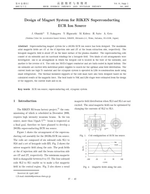
31 2007 7HIGH ENERGY PHYSICS AND NUCLEAR PHYSICSVol.31,Supp.Jul.,2007Design of Magnet System for RIKEN SuperconductingECR Ion SourceJ.Ohnishi1)T.Nakagawa Y.Higurashi M.Kidera H.Saito A.Goto (Nishina Cnter for Accelerator-based Science,RIKEN,Hirosawa2-1,Wako,Saitama,351-0198,Japan)Abstract Superconducting magnet system for a28GHz ECR ion source has been designed.The maximum axial magneticfields are4T at the rf injection side and2T at the beam extraction side,respectively.The hexapole magneticfield is about2T on the inner surface of the plasma chamber.The superconducting coils consist of six solenoids and six racetrack windings for a hexapolefield.Two kinds of coil arrangements were investigated:one is an arrangement in which the hexpole coil is located in the bore of the solenoids,and another is the reverse of it.The coils use NbTi-Copper conductor and are bath-cooled in liquid helium.The six solenoids are excited with individual power supplies to search for the optimal axialfield distribution.The current leads use high Tc material and the cryogenic system is operated in LHe re-condensation mode using small refrigerators.The thermal insulated supports of the cold mass have also been designed based on the calculated results of the magnetic force.The heat loads to70K and LHe stages were estimated from the design of the supports,the current leads and so on.Key words ECR ion source,superconducting coil,cryogenic system1IntroductionThe RIKEN RI-beam factory project,[1]the com-missioning of which is scheduled in December2006, requires high intensity uranium beams.In the ion source,more than15pµA U35+beam is requested as afinal goal,therefore we have planned to develop a 28GHz superconducting ECR ion source.Figure1shows the arrangement of the supercon-ducting coil assembly for the28GHz ECR ion source. The coils are composed of six solenoid coils SL1to SL6and a set of hexapole coils HX.Fig.2shows the mirror magneticfield along the axis.The peakfields at the rf injection side and the beam extraction side are4T and2T,respectively.The minimum magnetic field is changeable between0to1T.The four solenoid coils SL2to SL5enable us to make aflat magnetic field in the central region.Fig.2also shows a usual magneticfield distribution when SL3and SL4are not excited.The axial magneticfield can be optimized by changing the currents of SL2toSL5.Fig.1.Coil configuration of ECR ionsource.Fig.2.Magneticfields along the axis.38 (HEP&NP) 31SL1SL2SL3SL4SL5SL6HXJ.Ohnishi RIKEN ECR 39SL1SL2SL3SL4SL5SL6HXcoil becomes high,it is necessary to keep the inner radius of the hexapole coils small and as a result the diameter of the plasma chamber is restricted to about60—65mm.Fig.4.Coil configuration in which the hexapolecoil is located outside of thesolenoids.Fig.5.Magneticfield along the axis for the twokinds of coil configurations.3CryostatFigure6shows a cross section of the cryostat in which the hexapole coils are placed in the bore of the solenoid coils.The superconducting solenoid and hexapole coils are located in a LHe vessel and cooled by the bath-cooling.The amount of the LHe is about 500L.The cryostat is equipped with two or three small refrigerators for the4K and70K stages and operated without supplying LHe after poured once.The heat load to4K is estimated to be6W,which in-cludes3W due to X-ray irradiation from the plasma.A total of nine current leads made of high T c ma-terial are used to reduce the heat load to4K.The heat load to70K is estimated to be160W,which is caused by copper current leads,the supports of the cold mass and radiation through the multi-layer in-sulation.Magnetic shields with a thickness of50mm surround thecryostat.yout of the cryostat.The electromagnetic force between the magnetic shields and the cold mass is estimated to be80kN at the maximum in the axial direction when only the solenoid SL1is excited.The cold mass is supported with GFRP belts from the outer tank at room tem-perature.Four belts with a cross-section of300mm2 are used for the axial direction to support the axial force of up to100kN.On the other hand,eight belts with a cross-section of80mm2are used for each of the vertical and horizontal directions to support the force of up to50kN.Heat inputs to the4K and70K stages40 (HEP&NP) 31References1Yano Y.Proc.17th Int.Conf.on Cyclotrons and Their Applications,Tokyo,2004.169—1732Taylor C et al.IEEE Trans.Applied Superconductivity, 2000,10:2243ZHAO H.Proc.17th Int.Conf.on Cyclotrons and Their Applications,Tokyo,2004.269—271。
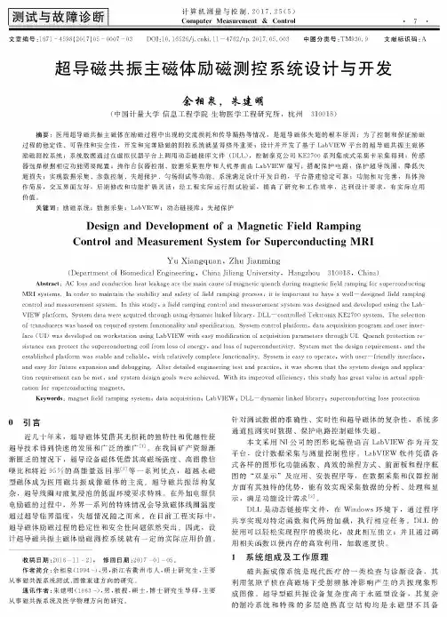
测试与故障诊断计算机测量与控制.2017. 25 (5) Computer Measurement & Control文章编号:1671 - 4598(2017)05 - 0007 -03DOI:10. 16526/j. cnkl 11-4762/tp. 2017. 05. 003 中图分类号:TM930. 9 文献标识码:A 超导磁共振主磁体励磁测控系统设计与开发会相泉,朱建明(中国计量大学信息工程学院生物医学工程研究所,杭州310018)摘要:医用超导磁共振主磁体在励磁过程中出现的交流损耗和传导漏热等情况,是超导磁体失超的根本原因;为了控制和保证励磁过程的稳定性、可靠性和安全性,开发和完善励磁的测控系统就显得格外重要;设计并开发了基于LabV IEW平台的超导磁共振主磁体励磁测控系统;系统数据通过在虚拟仪器平台上调用动态链接库文件(DLL),控制泰克公司K E2700系列集成式采集卡采集得到;传感 器选择根据相应功能需要配置;操作台仪器控制、数据采集程序和人机界面由LabV IEW编写;搭配保护电路,保护超导线圈,降低失 超损失;实现数据采集、参数控制、失超保护、勻场测试等功能。
系统满足设计开发目的,平台搭建稳定可靠;功能相对完善,具体操作简易,交互界面友好,后期修改和功能扩展灵活;经工程实际运行测试验证,提髙了研究和工作效率,达到设计要求,有实际应用价值。
关键词:励磁系统;数据采集;L ab V IE W;动态链接库;失超保护Design and Development of a Magnetic Field RampingControl and Measurement System for Superconducting MRIY u X i a n g q u a n,Z h u jia n m in g(Department of Biomedical Engineering,China jiliang University,Hangzhou310018 ,China) Abstract:AC loss and conduction heat leakage are the main cause of magnetic quench during magnetic field ramping for superconducting MRI systems. In order to maintain the stability and safety of field ramping process, it is important to have a well—designed field ramping control and measurement system. In this study, a field ramping control and measurement system was designed and developed using the Lab- VIEW platform. System data were acquired through using dynamic linked library, DLL—controlled Tektronix KE2700 system. The selection of transducers was based on required system functionality and specification. System control platform»data acquisition program and user interface (UI) was developed on workstation using LabVIEW with easy modification of acquisition parameters through UI. Quench protection resistance can protect the superconducting coil from loss of energy, and loss of superconductivity. System m established plaform was stable and reliable, with relatively complete functionality. System is easy to operate,with user —friendly interface, and easy for future expansion and debugging. After detailed engineering test and practice, it was shown that the system design and application requirement can be m et, and system design goals were achieved. W th t s improved efficiency, this study has great value rn actual application for superconducting magnets.Keywords:magnet field ramping system;data acquisition;LabVIEW;DLL—dynamic linked library;superconducting loss protection〇引言近几十年来,超导磁体凭借其无损耗的独特性和优越性使超导技术得到快速的发展和广泛的推广[1]。

HL-2A装置ECRH超导磁体磁场分布测量
白兴宇;黄梅;饶军
【期刊名称】《核聚变与等离子体物理》
【年(卷),期】2008(028)002
【摘要】测量了HL-2A装置ECRH超导磁体的磁场分布.测量结果析表明,其归一化纵向磁场在磁场中心20mm区域内大于0.992,径向分布在磁场中心平面上浮动小于1.48%,杂散场在贴近超导磁体表面时的最大分量小于50mT,满足实验要求.【总页数】4页(P154-157)
【作者】白兴宇;黄梅;饶军
【作者单位】清华大学,北京,100084;核工业西南物理研究院,成都,610041;核工业西南物理研究院,成都,610041
【正文语种】中文
【中图分类】TL62
【相关文献】
1.HL-2A装置ECRH回旋管磁场分布测量 [J], 白兴宇;饶军;黄梅;张劲松
2.HL-2A装置ECRH系统回旋管超导磁体的调试 [J], 黄梅;康自华;饶军;冯鲲;张劲松;雷建新
3.HL-2A装置ECRH系统传输效率的测量研究 [J], 王贺;陆志鸿;周俊;饶军;王超
4.HL-2A装置ECRH的微波强度分布测量与分析 [J], 黄梅;陈罡宇;饶军;周俊;刘永;康自华
5.HL-2A装置ECRH系统的微波功率测量 [J], 陆志鸿;易良碧;白兴宇;饶军
因版权原因,仅展示原文概要,查看原文内容请购买。