Sipex选型指南
- 格式:pdf
- 大小:819.00 KB
- 文档页数:12

第一章介绍此指南的第一章是介绍,介绍此指南的基本情况。
首先大家要明确一点,此指南是替代原先的3本指南,分别是ISPE 基准指南 5 调试与确认(第1版),ISPE指南:基于科学和风险的设施、系统和设备交付方法,ISPE良好实践指南:基于风险评估方法的调试与确认。
第二版指南的C&Q流程跟第一版完全不一样,下图是第一版中的C&Q流程,以V-模型为主要方式,强调确认源于设计的理念:ISPE Baseline® 第五卷《调试与确认》(第一版,2001)第二版则着重强调了与工艺参数和属性相匹配的系统从选型开始,至设计、确认的过程,以CQA和CPP为起点,如下图:ISPE Baseline® 第五卷《调试与确认》(第二版,2019)流程的第一步是输入,包括产品和工艺风险评估和控制策略所得的CQAs/CPPs,合并法规要求、操作要求、EHS要求等指导URS的编写,标记为蓝色的即是后面的每一章,从URS到定期审核,以及支持程序和执行策略。
我在后面的每一章介绍时会详细解读。
此指南最大的一个变化是风险评估方法的改变,由第一版的系统影响性评估(SIA)和部件关键性评估(CCA),变为系统影响性评估和关键设计元素基于决策树方式的系统级别判断和基于CQAs/CPPs的系统风险评估(SRA),在第3章和第4章会跟大家详细解读。
相关课程推荐扫码或者第一章介绍此指南是ISPE基准指南:调试与确认的第二版,所以此指南前一版中描述的C&Q方法的某些方面已经废弃,并被QRM和GEP取代,同时此指南提出了一些新的概念及方法。
废弃的方法和概念部件关键性评估:此评估方法被关键设计元素(CDE)所替代。
很多做过部件关键性评估的同事都说,系统影响性评估还简单一些,部件关键性评估太难了,如果供应商资料不全,如果对设备的几百个部件不了解,部件关键性评估根本无法开展。
我个人的建议,在设备首次验证的时候,部件关键性评估可以被关键设计元素(CDE)所替代,但是在设备维护保养及设备变更管理的时候,部件关键性评估还是一个很实用的工具。

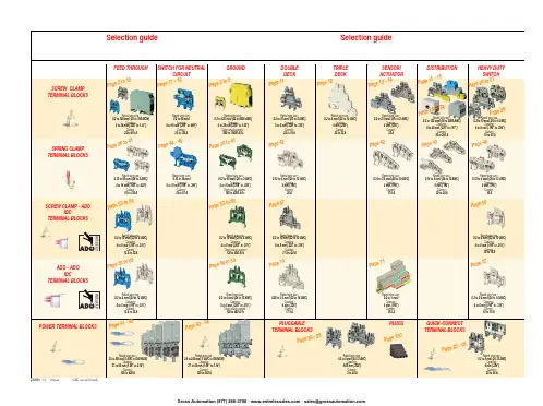
ABB EntrelecSommaireBU0402061SNC 160 003 C0205SummarySelection guide ....................................................................................page 1Screw clamp ........................................................................................page 2Feed through and ground terminal blocks .......................................................page 2 - 5 to 10Single pole, multiclamp terminal blocks..........................................................................page 4Feed through terminal blocks - Double-deck................................................................page 11Feed through terminal blocks - Triple-deck...................................................................page 12Three level sensor, terminal blocks without ground connection...................................page 13Three level sensor, terminal blocks with ground connection ........................................page 14Terminal blocks for distribution boxes, double deck + protection .......................page 15 - 16Interruptible terminal blocks for neutral circuit......................................................page 17 - 18Distribution : phase, ground terminal blocks .......................................................page 19 to 21Single pole or four pole distribution blocks..........................................................page 22 to 24Heavy duty switch terminal blocks with blade......................................................page 25 - 26Heavy duty switch terminal blocks with push-turn knob..............................................page 26Heavy duty switch terminal blocks with contact control pull lever...............................page 29Heavy duty switch terminal blocks with blade - Double-deck .....................................page 27Fuse holder terminal blocks for 5x20 mm (.197x.787 in.) and 5x25 mm (.197x.984 in.)or 6.35x25.4 mm (1/4x1 in.) and 6.35x32 mm (1/4x11/4 in.) fuse s.........................................page 28 - 29Fuse holder terminal blocks for 5x20 mm (.197x.787 in.) and 5x25 mm (.197x.984 in.) fuses -Double-dec k.....................................................................................................................page 27Terminal blocks for test circuits with sliding bridge ......................................................page 30Terminal blocks for metering circuits.............................................................................page 31ESSAILEC terminal blocks.............................................................................................page 32Safety connection terminal blocks ................................................................................page 33Miniblocks for EN 50045 (DIN 46277/2) rail ..........................................................page 34 - 35Spring clamp ......................................................................................page 36Angled terminal blocks - Feed through and ground .....................................................page 36Feed through and ground terminal blocks ...........................................................page 37 to 41Feed through terminal blocks - Double deck ................................................................page 42Terminal blocks for sensors / actuators ........................................................................page 42Terminal blocks for distribution boxes...........................................................................page 43Switch terminal blocks for neutral conductor........................................................page 44 - 45Heavy duty switch terminal blocks with blade..............................................................page 46Fuse holder terminal blocks for 5x20 mm (.197x.787 in.) and 5x25 mm (.197x.984 in.) fuse s....page 47Miniblocks Spring clamp ......................................................................................page 48 to 52ADO - Screw clamp ...........................................................................page 53Feed through and ground terminal blocks ...........................................................page 53 to 56Feed through and ground terminal blocks - Double-deck............................................page 57Heavy duty switch terminal blocks with blade..............................................................page 58Fuse holder terminal blocks for 5x20 mm (.197x.787 in.) and 5x25 mm (.197x.984 in.) fuse s ......page 59 - 60Miniblocks ADO - Screw clamp............................................................................page 61 to 65ADO - ADO .........................................................................................page 66Feed through and ground terminal blocks ...........................................................page 66 to 69Feed through and ground terminal blocks - Double-deck............................................page 70Terminal blocks for sensors / actuators ........................................................................page 71Heavy duty switch terminal blocks with blade..............................................................page 72Fuse holder terminal blocks for 5x20 mm (.197x.787 in.) and 5x25 mm (.197x.984 in.) fuse s ......page 73 - 74Miniblocks ADO - ADO .........................................................................................page 75 to 79Accessories ADO ...........................................................................................................page 80Power terminal blocks .............................................................page 81 to 84Quick-connect terminal blocks .................................................page 85 - 86Terminal blocks for railway applications ................................page 87 to 97Pluggable terminal blocks .....................................................page 98 to 100Accessories......................................................................................page 101Marking..................................................................................page 102 to 104GrossAutomation(877)268-3700··*************************PR30PR3.Z2PR3.G2PR5PR4PR1.Z2Rated wire size :Rated wire size :Rated wire size :Rated wire size :Mounting railsShield terminals forcollector barMarking tableHorizontal Rated wire size :0.5 to 16 mm² (22 to 8 AWG)Rated wire size :Rated wire size :Rated wire size :P a g e t o 29e30 t o 32ag e e3P a ge 8 t o 60a g e6t o 6574P a ge 7 t o 79P a ge 9P a g P a gGrossAutomation(877)268-3700··*************************2ABB Entrelecd010830402051SNC 160 003 C0205MA 2,5/5 - 2.5 mm² blocks - 5 mm .200" spacingAccessoriesGrossAutomation(877)268-3700··*************************3ABB Entrelec D010740402051SNC 160 003 C0205M 4/6 - 4 mm² blocks - 6 mm .238" spacingAccessoriesGrossAutomation(877)268-3700··*************************4ABB EntrelecD011030402051SNC 160 003 C0205M 4/6.3A - 4 mm² blocks - 6 mm .238" spacingM 4/6.4A - 4 mm² blocks - 6 mm .238" spacingGrossAutomation(877)268-3700··*************************5ABB Entrelec D010840402051SNC 160 003 C0205M 6/8 - 6 mm² blocks - 8 mm .315" spacingAccessoriesGrossAutomation(877)268-3700··*************************6ABB EntrelecD010850402051SNC 160 003 C0205M 10/10 - 10 mm² blocks - 10 mm .394" spacingAccessoriesGrossAutomation(877)268-3700··*************************7ABB Entrelec D010860402051SNC 160 003 C0205M 16/12 - 16 mm² blocks - 12 mm .473" spacingAccessoriesGrossAutomation(877)268-3700··*************************8ABB EntrelecD010870402051SNC 160 003 C0205M 35/16 - 35 mm² blocks - 16 mm .630" spacingGrossAutomation(877)268-3700··*************************M 95/26 - 95 mm² blocks - 26 mm 1.02" spacingM 70/22.P - 70 mm² ground block with rail contact - 22 mm .630" spacingSelection35 mm / 1.37"12 mm / 0.47"14-30 Nm / 124-260 Ib.in 1.2-1.4 Nm / 10.6-12.3 Ib.in1000600600415400400577070240 mm 2500 MCM 500 MCM 10 mm 2 6 AWG 6 AWG IEC UL CSANFC DIN0.5 - 160.5 - 100 AWG-600 MCM 2 AWG-500 MCM 50 - 30035 - 24018-6 AWGD 150/31.D10 - 150 mm² blocks - 31 mm 1.22" spacingCharacteristicsD 240/36.D10 - 240 mm² blocks - 36 mm 1.41" spacingSelectionWire size main circuit mm² / AWG VoltageV Current main circuit A Current outputARated wire size main circuit mm² / AWG Rated wire size outputmm² / AWG Wire stripping length main circuit mm / inches Wire stripping length output mm / inches Recommended torque main circuit Nm / Ib.in Recommended torque outputNm / Ib.inSolid Stranded Solid Stranded Wire size output mm² / AWG9.5 mm / .37"0.5-0.8 Nm / 4.4-7.1 Ib.in5003003003220204 mm 212 AWG12 AWG0.2 - 422-12 AWG 22-12 AWG 0.22 - 4IEC ULCSANFC DINCharacteristicsWire size mm² / AWGSolid Stranded D 4/6.T3 - 4 mm² blocks - 6 mm .238" spacingSelectionVoltage V CurrentARated wire sizemm² / AWG Wire stripping length mm / inches Recommended torqueNm / Ib.inM 4/6.T3.P - 4 mm² block - 6 mm .238" spacingD 2,5/6.D - 2.5 mm² blocks - 6 mm .238" spacingD 2,5/6.DL - 2.5 mm² blocks - 6 mm .238" spacingD 2,5/6.DPA1 - 2.5 mm² blocks - 6 mm .238" spacingD 2,5/6.DPAL1 - 2.5 mm² blocks - 6 mm .238" spacingD 4/6... - 4 mm² blocks - 6 mm .238" spacingD 4/6.LNTP - 4 mm² closed blocks - 17.8 mm .700" spacingMA 2,5/5.NT- 2.5 mm² block - 5 mm .200" spacingAccessories**SFB2 : 16 to 35 mm² 6 to 2 AWG H= 3 mm/.12"M 10/10.NT- 10 mm² block - 10 mm .394" spacingAccessories(1) Except for M 35/16 NT (closed block)*SFB1 : 0.5 to 35 mm² 18 to 2 AWG H= 7 mm/.28"**SFB2 : 16 to 35 mm² 6 to 2 AWG H= 3 mm/.12"MB 4/6... - 4 mm² blocks - 6 mm .238" spacingMB 6/8... - 6 mm² blocks - 8 mm .315" spacingMB 10/10... - 10 mm² blocks - 10 mm .394" spacingBRU 125 A - 35 mm² block - 27 mm 1.063" spacingBRU 160 A - 70 mm² block - 35.2 mm 1.388" spacingBRU 250 A - 120 mm² blocks - 44.5 mm 1.752" spacingBRU 400 A - 185 mm² block - 44.5 mm 1.752" spacingAccessoriesAccessoriesBRT 80 A - 16 mm² block - 48 mm 1.89" spacingBRT 125 A - 35 mm² block - 48 mm 1.89" spacingBRT 160 A - 50 mm² block - 50 mm 1.97" spacing9.5 mm / .37"0.5-0.6 Nm / 4.4-5.3 Ib.in4003003002010104 mm 210 AWG 12 AWG 0.5 - 422-10 AWG20-12 AWG0.5 - 2.5IEC ULCSANFC DINMA 2,5/5.SNB - 2.5 mm² blocks - 5 mm .200" spacingCharacteristicsM 4/6.SNB - 4 mm² blocks - 6 mm .238" spacingSelectionWire size mm² / AWGVoltage V CurrentARated wire sizemm² / AWG Wire stripping length mm / inches Recommended torqueNm / Ib.inSolid StrandedM 6/8.SNB - 6 mm² blocks - 8 mm .315" spacing - blade switchingSelectionAccessoriesM 4/8.D2.SF - for fuses 5x20 mm .197x.787 in. and 5x25 mm .197x.984 in. -4 mm² blocks - 8 mm .315" spacingM 4/6.D2.SNBT - 4 mm² blocks - 6 mm .238" spacing - blade switchM 4/8.SF- 4 mm² blocks - 8 mm .315" spacingM 4/8.SFL - 4 mm² blocks - 8 mm .315" spacing12 mm / .472"1.2-1.4 Nm / 10.6-12.3 Ib.in800(1)60060016252510 mm 210 AWG8 AWG0.5 - 1622-10 AWG 22-8 AWG 0.5 - 10IEC ULCSANFC DINCBD2SML 10/13.SF - for fuses 6.35x25.4 mm 1/4x1 in. and 6.35x32 mm 1/4x11/4 in. -10 mm² blocks - 13 mm .512" spacingSelectionAccessoriesCharacteristicsWire size mm² / AWGVoltage V CurrentARated wire sizemm² / AWG Wire stripping length mm / inches Recommended torqueNm / Ib.inSolid Stranded (1) Insulation voltage of terminal block - operating voltage : according to fuse.M 4/6.D2.2S2... - 4 mm² blocks - 6 mm .238" spacing11 mm / .43"0.8-1 Nm / 7.1-8.9 Ib.in50060030306 mm 28 AWG0.5 - 1022-8 AWG0.5 - 6IECULCSANFC DINM 6/8.ST... - 6 mm² blocks - 8 mm .315" spacingCharacteristicsWire size mm² / AWGVoltage V CurrentARated wire sizemm² / AWG Wire stripping length mm / inches Recommended torqueNm / Ib.inSolid Stranded M 6/8.STA - 6 mm² blocks - 8 mm .315" spacing(3)Only for M 6/8.STAM 4/6.ST- 4 mm² blocks - 6 mm .236" spacingBNT...PC...(2) Only for M10/10.ST-SnThe PREM IUM solution for testing the secondary circuits of current or voltage transformers.ESSAILEC, approved by the major electricity utilities, remains the premium choice for the energy market.Implemented in the transformers secondary circuits, ESSAILEC thanks to its intelligent “make before break” design eases and secures any intervention. Cutting the energy supply is avoided with zero risk for the operator.The plug and socket connection cuts cost installation as well as in-situ wiring errors. ESSAILEC is ideal for the wiring of sub-assemblies in the secondary circuits.ESSAILEC terminal blocksProtection relays,Protection relays,Testing :The ESSAILEC socket supplies energy to the protection or counting devices. The insertion of the test plug, which is connected to the measurement equipment, allows the testing of the devices, without perturbing the circuit.ESSAILEC blocks are well adapted to current or voltage measurement :-Current sockets with make before break contacts and pre-wired test plug for current measures-Voltage sockets with open contacts and pre-wired test plug for voltage measures-Up to 4 ammeters or 4 voltmeters connected to the test plugDistributing :The ESSAILEC plug is continuously mounted on the socket to supply current or voltage to secondary circuits sub assemblies.ESSAILEC blocks extreme versatility allow :-Safe current distribution with current socket with mobile contacts since the secondary circuit is not cut when plug is removed-Voltage or polarity distribution with dedicated voltage or polarity socket with closed contactESSAILEC is designed to offer :Great flexibility :-Connection multi contacts « plug and play »-Panel, rail, rack fixed mounting or stand-alone connector -Two wiring technologies, up to 10 mm²Extreme reliability :-Non symmetric blocks -Coding accessories -IP20 design -Locking system -Sealed coverR S T NFor technical characteristics and complete part numbers list, please ask for the ESSAILEC catalog10005006003225254 mm 21.65 mm²12 AWG 13 mm / .51"IECB.SCSANFC DINTS 50-180.5 - 0.8 Nm /4.4 - 7.1 Ib.in0.2 - 422-12 AWG0.22 - 40.5 - 1.50.28 - 1.6580050060041252562.512 AWG 13 mm / .51"0.8 - 1 Nm / 7.1 - 8.9 Ib.inIECB.S CSANFC DINTS 50-180.5 - 1020-12 AWG0.5 - 60.28 - 2.590050060046406510 mm 26 mm² 6 AWG 14 mm / .55"IECB.S UL/CSANFC DINTS 50-181.2 - 1.4 Nm / 10.6 - 12.3 Ib.in0.5 - 1620 - 6 AWG0.5 - 100.28 - 6M 4/6.RS - 4 mm² blocks - 6 mm .238" spacingCharacteristicsWire size mm² / AWGVoltage V CurrentARated wire sizemm² / AWG Wire stripping lengthmm / inches Recommended torque (screw)Nm / Ib.inSolid wire Stranded wire Solid wire Stranded wire Screw clampLugsM 6/8.RS - 6 mm² blocks - 8 mm .315" spacingCharacteristicsWire size mm² / AWGVoltage V CurrentARated wire sizemm² / AWG Wire stripping lengthmm / inches Recommended torque (screw)Nm / Ib.inSolid wire Stranded wire Solid wire Stranded wire Screw clampLugspending M 10/10.RS - 10 mm² blocks - 10 mm .394" spacingCharacteristicsWire size mm² / AWGVoltage V CurrentARated wire sizemm² / AWG Wire stripping lengthmm / inches Recommended torque (screw)Nm / Ib.inSolid wire Stranded wire Solid wire Stranded wire Screw clampLugspending SelectionAccessories(1) Only for block M 4/6.RS (4) For blocks M 4/6.RS and M 6/8.RS(2) Only for block M 6/8.RS(3) Only for block M 10/10.RSDR 1,5/4 - 1.5 mm² blocks - 4 mm .157" spacingDR 1,5/5... - 1.5 mm² blocks - 5 mm .200" spacing。

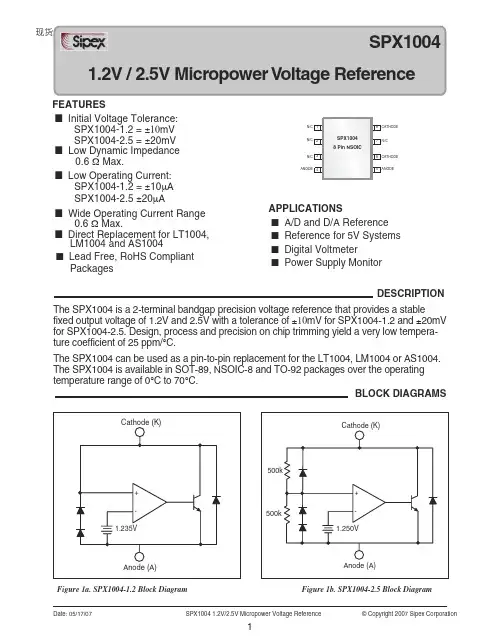
现货库存、技术资料、百科信息、热点资讯,精彩尽在鼎好!Date: 05/17/07 SPX1004 1.2V/2.5V Micropower Voltage Reference© Copyright 2007 Sipex CorporationAPPLICATIONS■ A/D and D/A Reference ■ Reference for 5V Systems ■ Digital Voltmeter■ Power Supply MonitorBLOCK DIAGRAMS1.2V /2.5V Micropower V Figure 1a. SPX1004-1.2 Block Diagram Figure 1b. SPX1004-2.5 Block DiagramThe SPX1004 is a 2-terminal bandgap precision voltage reference that provides a stablefixed output voltage of 1.2V and 2.5V with a tolerance of ±10mV for SPX1004-1.2 and ±20mV for SPX1004-2.5. Design, process and precision on chip trimming yield a very low tempera-ture coefficient of 25 ppm/°C.The SPX1004 can be used as a pin-to-pin replacement for the LT1004, LM1004 or AS1004. The SPX1004 is available in SOT-89, N SOIC-8 and TO-92 packages over the operating temperature range of 0°C to 70°C.DESCRIPTION■ Lead Free, RoHS Compliant PackagesFEATURES■ Initial Voltage Tolerance: SPX1004-1.2 = ±10mV SPX1004-2.5 = ±20mV ■ Low Dynamic Impedance0.6 Ω Max.■ Low Operating Current: SPX1004-1.2 = ±10µA SPX1004-2.5 ±20µA■ Wide Operating Current Range 0.6 Ω Max.■ Direct Replacement for LT1004,LM1004 and AS1004Date: 05/17/07 SPX1004 1.2V/2.5V Micropower Voltage Reference© Copyright 2007 Sipex CorporationElectrical characteristics are guaranteed over full junction temperature range (0°C to 70°C). Ambient temperature must bederated based on power dissipation and package thermal characteristics.SPX1004-1.2V SPX1004-2.5VPARAMETER CONDITIONS MIN TYP MAX MIN TYP MAX UNITS Reverse breakdown I Z =100µA, T J =25°C 1.225 1.235 1.245 2.480 2.500 2.520 V0°C ≤T A ≤70°C 1.219 1.235 1.251 2.470 2.500 2.530Ave Temp. Coeff. I min ≤I Z ≤20mA 20 60 ppm/°CMin Operating Current 4 10 12 20 µA Reverse Breakdown I min ≤I Z ≤1mA 0.5 1 0.5 1 mV Voltage Change over temperature 0.5 1.5 0.5 1.5with Current 1mA ≤I Z ≤20mA 6.5 10 6.5 10over temperature 6.5 20 6.5 20Reverse Dynamic I Z =100µA, f=25Hz 0.2 0.6 0.8 0.9 ΩImpedance over temperature 1 1.5 1.5Wide Band Noise I Z =100µA, 10Hz ≤f ≤10kHz 60 120 µV Long Term Stability I Z =100µA, T A =25°C ±0.1°C 20 60 ppm/kHrOperating Temp Range 0 70 0 70 °CABSOLUTE MAXIMUM RATINGSStresses greater than those listed under ABSOLUTE MAXIMUM RATINGS may cause permanent damage to the device. This is a stress rating only and functional operation of the device at these or any other conditions above those indicated in the operational sections of this specification is not implied. Exposure to absolute maximum rating conditions for extended periods may affect reliability.Forward Current (I AK ).....................................................10mA Reverse Current (I KA ).....................................................30mA Lead Temperature (soldering, 10 seconds).................300°C Storage Temperature Range.......................-65°C to +150°C Junction Temperature..................................................150°CContinuous Power Dissipation (P D )TO-92.........................................................775mW N SOIC-8.....................................................750mW SOT-89.....................................................1000mWFigure 2. V REF vs Temperature for 2.5V VersionTYPICAL THERMAL RESISTANCESPACKAGE- 0JA TYPICALDERATING TO-92 160°C/W 80°C/W 6.3 mW/°C NSOIC-8 175°C/W 45°C/W 5.7mW/°C SOT-89110°C/W8°C/W9.1mW/°CELECTRICAL CHARACTERISTICS0JA-TYPICAL PERFORMANCE CHARACTERISTICSFigure 7. Forward Characteristics for SPX1004-1.2 Figure 8. Low Frequency Reverse Dynamic Impedanceand SPX1004-2.5 for SPX1004-1.2Date: 05/17/07 SPX1004 1.2V/2.5V Micropower Voltage Reference © Copyright 2007 Sipex CorporationAPPLICATION CIRCUITSFigure 9a. 1.2V Reference, Figure 9b. 2.5V Reference Figure 10. Low Noise ReferenceFigure 11. Variable Output Regulator Figure 12. High Stability 5V RegulatorFigure 13. Low Battery Detector Figure 14. Micropower 10V ReferenceDate: 05/17/07 SPX1004 1.2V/2.5V Micropower Voltage Reference © Copyright 2007 Sipex CorporationDate: 05/17/07 SPX1004 1.2V/2.5V Micropower Voltage Reference © Copyright 2007 Sipex CorporationPACKAGE: 3 PIN SOT-89PACKAGE: PINOUTSTop View SOT-89 (M1)Bottom ViewTO-92 (N)CATHODETop View 21348 7 6 5N SOIC (S2) Alternate Pin OutCATHODE ANODEN/C N/C N/C CATHODEN/C N/CANODETop View 21348 7 6 5N SOIC (S1)CATHODE ANODEN/C N/C N/C CATHODE N/CANODEDate: 05/17/07 SPX1004 1.2V/2.5V Micropower Voltage Reference © Copyright 2007 Sipex CorporationDate: 05/17/07 SPX1004 1.2V/2.5V Micropower Voltage Reference © Copyright 2007 Sipex CorporationORDERING INFORMATIONPart Number Accuracy OutputVoltageMSL Level RoHS Package Pack Type Quantity SPX1004AS1-L-1-2 0.8% 1.235V L1 @ 260ºC Yes NSOIC8 TUBE 98 SPX1004AS1-L-1-2/TR 0.8% 1.235V L1 @ 260ºC Yes NSOIC8 Tape & Reel 2500SPX1004AS2-L-1-2 0.8% 1.235V L1 @ 260ºC YesNSOIC8Alt. PinoutTUBE 98SPX1004AS2-L-1-2/TR 0.8% 1.235V L1 @ 260ºC Yes NSOIC8 Tape & Reel 2500 SPX1004S1-L-1-2 0.8% 1.235V L1 @ 260ºC Yes NSOIC8 TUBE 98 SPX1004S1-L-1-2/TR 0.8% 1.235V L1 @ 260ºC Yes NSOIC8 Tape & Reel 2500SPX1004S2-L-1-2 0.8% 1.235V L1 @ 260ºC YesNSOIC8Alt. PinoutTUBE 98SPX1004S2-L-1-2/TR 0.8% 1.235V L1 @ 260ºC YesNSOIC8Alt. PinoutTape & Reel 2500SPX1004AM1-L-1-2 0.8% 1.235V L2 @ 260ºC Yes SOT-89-3 Canister Any SPX1004AM1-L-1-2/TR 0.8% 1.235V L2 @ 260ºC Yes SOT-89-3 Tape & Reel 2500 SPX1004M-L-1-2 0.8% 1.235V L2 @ 260ºC Yes SOT-89-3 Canister Any SPX1004M-L-1-2/TR 0.8% 1.235V L2 @ 260ºC Yes SOT-89-3 Tape & Reel 2500SPX1004AN-L-1-2 0.8% 1.235V No MSL for thruhole package.Yes TO-92-3 BOX AnySPX1004AN-L-1-2/TR 0.8% 1.235V No MSL for thruhole package.Yes TO-92-3 Tape & Reel 2000SPX1004N-L-1-2 0.8% 1.235V No MSL for thruhole package.Yes TO-92-3 BOX AnySPX1004N-L-1-2/TR 0.8% 1.235V No MSL for thruhole package.Yes TO-92-3 Tape & Reel 2000SPX1004AS1-1-2 0.8% 1.235V L1 @ 240ºC No NSOIC8 TUBE 98 SPX1004AS1-1-2/TR 0.8% 1.235V L1 @ 240ºC No NSOIC8 Tape & Reel 2500SPX1004AS2-1-2 0.8% 1.235V L1 @ 240ºC NoNSOIC8Alt. PinoutTUBE 98SPX1004AS2-1-2/TR 0.8% 1.235V L1 @ 240ºC NoNSOIC8Alt. PinoutTape & Reel 2500SPX1004S1-1-2 0.8% 1.235V L1 @ 240ºC No NSOIC8 TUBE 98 SPX1004S1-1-2/TR 0.8% 1.235V L1 @ 240ºC No NSOIC8 Tape & Reel 2500SPX1004S2-1-2 0.8% 1.235V L1 @ 240ºC NoNSOIC8Alt. PinoutTUBE 98SPX1004S2-1-2/TR 0.8% 1.235V L1 @ 240ºC NoNSOIC8Alt. PinoutTape & Reel 2500SPX1004AM1-1-2 0.8% 1.235V L1 @ 240ºC No SOT-89-3 Canister Any SPX1004AM1-1-2/TR 0.8% 1.235V L1 @ 240ºC No SOT-89-3 Tape & Reel 2500 SPX1004M1-1-2 0.8% 1.235V L1 @ 240ºC No SOT-89-3 Canister Any SPX1004M1-1-2/TR 0.8% 1.235V L1 @ 240ºC No SOT-89-3 Tape & Reel 2500 SPX1004M-1-2 0.8% 1.235V L1 @ 240ºC No SOT-89-3 Canister Any SPX1004M-1-2/TR 0.8% 1.235V L1 @ 240ºC No SOT-89-3 Tape & Reel 2500SPX1004AN-1-2 0.8% 1.235V No MSL for thruhole package.No TO-92-3 BOX AnySPX1004AN-1-2/TR 0.8% 1.235V No MSL for thruhole package.No TO-92-3 Tape & Reel 2000SPX1004N-1-2 0.8% 1.235V No MSL for thruhole package.No TO-92-3 BOX AnySPX1004N-1-2/TR 0.8% 1.235V No MSL for thruhole package.No TO-92-3 Tape & Reel 2000Date: 05/17/07 SPX1004 1.2V/2.5V Micropower Voltage Reference © Copyright 2007 Sipex CorporationORDERING INFORMATION (continued)Part Number Accuracy Output Voltage MSL Level RoHS Package Pack Type QuantitySPX1004S1-L-2-5 0.8% 2.500V L1 @ 260ºC Yes NSOIC8 TUBE 98SPX1004S1-L-2-5/TR 0.8% 2.500V L1 @ 260ºC Yes NSOIC8 Tape & Reel 2500SPX1004S2-L-2-5 0.8% 2.500V L1 @ 260ºC Yes NSOIC8 Alt. Pinout TUBE 98SPX1004S2-L-2-5/TR 0.8% 2.500V L1 @ 260ºC Yes NSOIC8 Alt. Pinout Tape & Reel 2500SPX1004M1-L-2-5 0.8% 2.500V L2 @ 260ºC Yes SOT-89-3 Canister AnySPX1004M1-L-2-5/TR 0.8% 2.500V L2 @ 260ºC Yes SOT-89-3 Tape & Reel 2500SPX1004M-L-2-5 0.8% 2.500V L2 @ 260ºC Yes SOT-89-3 Canister Any SPX1004M-L-2-5/TR 0.8% 2.500V L2 @ 260ºC Yes SOT-89-3 Tape & Reel2500SPX1004N-L-2-5 0.8% 2.500V No MSL for thru hole package. Yes TO-92-3 BOX Any SPX1004N-L-2-5/TR 0.8% 2.500V No MSL for thru hole package. Yes TO-92-3 Tape & Reel 2000SPX1004S1-2-5 0.8% 2.500V L1 @ 240ºC No NSOIC8 TUBE 98SPX1004S1-2-5/TR 0.8% 2.500V L1 @ 240ºC No NSOIC8 Tape & Reel 2500SPX1004S2-2-5 0.8% 2.500V L1 @ 240ºC No NSOIC8 Alt. Pinout TUBE 98SPX1004S2-2-5/TR 0.8% 2.500V L1 @ 240ºC No NSOIC8 Alt. Pinout Tape & Reel 2500SPX1004M1-2-5 0.8% 2.500V L1 @ 240ºC No SOT-89-3 Canister Any SPX1004M1-2-5/TR 0.8% 2.500V L1 @ 240ºC No SOT-89-3 Tape & Reel 2500SPX1004M-2-5 0.8% 2.500V L1 @ 240ºC No SOT-89-3 Canister Any SPX1004M-2-5/TR 0.8% 2.500V L1 @ 240ºC No SOT-89-3 Tape & Reel2500SPX1004N-2-5 0.8% 2.500V No MSL for thru hole package. No TO-92-3 BOX Any SPX1004N-2-5/TR0.8%2.500VNo MSL for thru hole package.NoTO-92-3Tape & Reel2000For latest information on ordering status, go to the Sipex Web Landing Page for this product /searchResults.aspx?keywordsval=spx1004For further assistance:Email: **********************WWW Support page: /content.aspx?p=support Sipex Application Notes: /applicationNotes.aspxMilpitas, CA 95035 tel: (408) 934-7500 fax: (408) 935-7600Sipex Corporation reserves the right to make changes to any products described herein. Sipex does not assume any liability arising out of the application or use of any product or circuit described herein; neither does it convey any license under its patent rights nor the rights of others.。
ISPE制药工程指南系列《无菌生产设施》读书笔记ISPE制药工程基准指南系列《无菌生产设施》第2版读书笔记1.美国和欧盟GMP的原则是:1)当用无菌工艺生产无菌API或制剂时,在无菌性方面的要求是一致的,无任何变化。
2)如无菌活性成分(APIs)直接分装成制剂,则无菌制剂的GMP要求适用于APIs生产。
2.药品质量管理规范(GMP)在各国的习惯称呼有所不同。
美国使用缩写CGMP,而欧洲,日本和其他地区缩写成GMP。
3.有6个工艺步骤建议需要对时间进行控制:1)配制至灭菌的时间;2)过滤时间;3)生产线上产品暴露时间;4)设备部件灭菌后的存储期;5)胶塞清洗/干燥后至灭菌的时间;6)灭菌后的容器/胶塞的存储期。
4.无菌产品的风险评估:4.1早期需考虑的3个关键问题(l)剂型:液体,乳剂,粉末或半固体;2)产品是否促进微生物生长:3)产品是否有潜在毒性或毒性,生产时可能对人员造成伤害。
4.2无菌生产工艺的关键工艺步骤:1)包装(西林瓶,安凯等等);2)规模或产量的要求;3)产品如何进出生产区域:4)是否有亚批或连续工艺(例如灭菌隧道):5)潜在的交叉污染,对敏感成分需早期考虑;6)通过设计或其他控制方法降低风险。
4.3结合产能和规模设计时应考虑以下内容:1)批量;2)批或阶段性生产周期;3)灌装重量和体积;4)生产线转换频率;4)清洁;5)消毒;6)灭菌需求。
5.无菌产品生产的关键工艺步骤:1)配料;2)配制和无菌过滤;3)转运至冻干机;4)灌装和加塞(初级密封):5)直接接触产品的容器和胶塞的准备,灭菌和除热原;6)已灭菌设备和部件的储存和转运;7)工艺储罐和直接接触产品设备的清洁和灭菌。
6.无菌产品保护和避免污染:1)通过人员,物料或设备污染(例如设备表面或内部残留物或清洁剂/物料转运至控制区时的污染/人员在不同生产区域移动造成的污染/人员产生的污染);2造成化学和生物污染的其它物质有:灰尘/污垢/毛屑/有毒物质/内毒素/引发感染的物质/生物试剂。
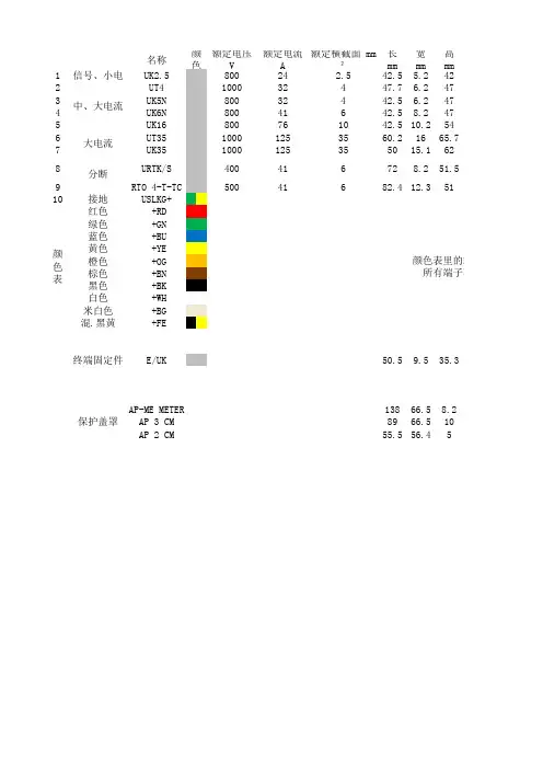
名称额定电压 V额定电流 A额定横截面 mm²长 mm 宽 mm 高 mm1信号、小电流UK2.580024 2.542.5 5.2422UT4100032447.7 6.2473UK5N 80032442.5 6.2474UK6N 80041642.58.2475UK16800761042.510.2546UT3510001253560.21665.77UK351000125355015.1628URTK/S 400416728.251.59RTO 4-T-TC 50041682.412.35110接地USLKG+红色 +RD 绿色 +GN 蓝色 +BU 黄色 +YE 橙色 +OG 棕色 +BN 黑色 +BK 白色 +WH 米白色 +BG 混.黑黄+FE终端固定件E/UK 50.59.535.3AP-ME METER 13866.58.2AP 3 CM 8966.510AP 2 CM 55.556.45分断大电流保护盖罩中、大电流颜色颜色表颜色表里的端子所有端子不一定有颜色表里端板隔板桥接件 螺桥接件 插标识条D-UK2.5ATP-UK FBRI 10-5N EBL 10-5ZB5 LGS1-9D-UT 2,5/10ATP-UK FBS 10-6ZB6 LGS1-10D-UK4/10ATP-UK FBI 10-6EB 10-6ZB6 LGS1-10D-UK4/10ATP-UK FBI 10-8EB 10-8ZB6 LGS1-10D-UK16ATP-UK FBI 10-10EB 10-10ZB10 LGS1-10TPNS-UK FBS 2-16ZB16 LGS1-10KT-S FBI 3-15D-URTK ATS-RTK FB 10-RTK/SSB 4-RTK/SEB 10-8ZB8 LGS1-10D-RT4-TTPNS-UKFBS 10-6ZB8 LGS1-10KLM-A终端固定架中间支撑架APH-ME APT-ME AP 3-TNS 35AP 3-TU AP 2-TU KS AP 2-TU附件:的端子颜色越不常用货期越长。

部分产品快速选型手册 2011/2012 海格电气公司为了给中国市场广大用户提供更好的产品服务,我们现将原在公司内部物流管理层所用的部分产品物流编号(物流型号,开放给广大用户使用,并据此重新编制了对应的空气断路器和塑壳断路器的“快速选型手册”。
当用户使用本手册时,需要参考以前刊印的海格产品选型手册相关内容。
我们保证了原“产品样本型号”与内部的“物流型号”在对同一特定产品的唯一性。
在工程设计中,无论使用“产品样本型号”还是“物流型号” 都可由用户自愿选择。
当然使用“物流型号”会给用户带来某些方面的便利。
这也是我们公布“物流型号”的初衷。
我们声明:海格电气公司保留今后对产品型号解释权。
如有疑问欢迎咨询海格电气公司市场部及销售人员。
非常感谢广大客户长期以来对海格电气公司的支持和信赖,我们承诺:继续做好对中国市场广大客户的产品服务。
谨礼!目录 ACB产品物流型号命名方法 HDC系列MCCB物流型号命名方法 HBC系列MCCB物流型号命名方法 HVN系列ELCB物流型号命名方法MSG选型对照表(ACB/MCCB 1 2 3 4 5 25 27 29 附录:基本术语常用公式2011/2012年年历分断能力字母代码说明样本型号分断能力的字母表示 H N E S P ACB 55KA 65KA 80KA 物流型号分断能力的字母表示 HDC HBC ELCB 25KA35KA 35KA 50KA 50KA 50KA 80KA HDC HBC ELCB ACB 25KA H 55KA 35KA50KA F 50KA 50KA N 65KA 80KA E 80KA S 80KA 100KA P 100KA 1 ACB产品物流型号命名方法 HW 附件 N 1000A D / 3P / LSI / HW:海格主开关系列空气断路器分断能力 N:65kA(框架I、II) S:80kA (框架II、III) P:100kA(框架III)控制器 LS-两段式 LSLCD两段式,液晶屏 LSI-三段式 LSILCD-三段式.液晶屏 LSIG-四段式 LSIGLCD-四段式,液晶屏可选附件 MX: 分励继电器 (电压可选择 UV: 欠压继电器 (瞬时 (电压可选择 UV-D: 欠压继电器 (延时 (电压可选择 CF: 故障指示触点MH: 储能电机 (电压可选择 PF: 准备合闸触点 BL: OFF锁代号 (详见样本安装形式F-固定式 D-抽出式标配附件 4NO+4NC辅助触点分励继电器(电压可选择合闸继电器(电压可选择储能电机 (电压可选择框架II: 2000A 2500A 额定电流(A 框架I: 630A 800A 1000A 1250A 1600A 框架III:3200A 4000A 极数 3P(可以缺省 4P 注: 附件需要标出电压时230Vac可缺省举例:HWN1600A/ D/3P/ LSI /UV+CF 说明:In=1600A,分断能力65kA,抽出式,3P,三段式保护控制器,带故障指示触点,欠压继电器。
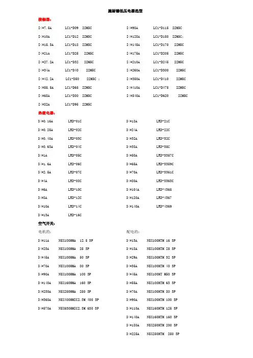
施耐德低压电器选型接触器:I<=7.5A LC1-D09 22M5C I<=10A LC1-D12 22M5C I<=15.3A LC1-D18 22M5C I<=21A LC1-D25 22M5CI<=27.2A LC1-D32 22M5CI<=34A LC1-D40 22M5C I<=42.2A LC1-D50 22M5C ;I<=55.5A LC1-D65 22M5CI<=68A LC1-D80 22M5CI<=82A LC1-D95 22M5C I<=98A LC1-D115 22M5CI<=128A LC1-D150 22M5C;I<=145A LC1-D170 22M5CI<=175A LC1-D205 22M5CI<=210A LC1-D245 22M5CI<=260A LC1-D300 22M5C I<=350A LC1-D410 22M5C I<=410A LC1-D475 22M5C I<=540A LC1-D620 22M5C热继电器:I<=0.16A LRD-01C I<=0.25A LRD-02C I<=0.40A LRD-03C I<=0.63A LRD-04C I<=1A LRD-05C I<=1.6A LRD-06C I<=2.5A LRD-07C I<=4A LRD-08C I<=6A LRD-10C I<=8A LRD-12C I<=10A LRD-14C I<=13A LRD-16C I<=18A LRD-21C I<=24A LRD-22C I<=32A LRD-32C I<=38A LRD-35C I<=50A LRD-3357C I<=65A LRD-3359C I<=70A LRD-3361C I<=80A LRD-3363C I<=104A LRD-4365 I<=120A LRD-4367 I<=140A LRD-4369空气开关:电机的:I<=11A NSX100HMA 12.5 3PI<=23A NSX100HMA 25 3PI<=45A NSX100HMA 50 3PI<=70A NSX100HMA 80 3PI<=90A NSX100HMA 100 3PI<=140A NSX160HMA 160 3PI<=230A NSX250HMA 250 3PI<=360A NSX400HMIC2.3M 400 3P I<=570A NSX630HMIC2.3M 630 3P 配电的:I<=13A NSX100HTM 16 3PI<=18A NSX100HTM 25 3PI<=29A NSX100HTM 32 3PI<=35A NSX100HTM 40 3PI<=45A NSX100HT M50 3PI<=55A NSX100HTM 63 3PI<=70A NSX100HTM 80 3PI<=90A NSX100HTM 100 3P I<=110A NSX160HTM 125 3P I<=140A NSX160HTM 160 3P I<=180A NSX250HTM 200 3P I<=225A NSX250HTM 250 3PI<=360A NSX400HMIC2.3 400 3P I<=600A NSX630HMIC2.3 630 3P三、中间继电器40、31、22CA2-DN□□M5C常闭接点数量常开接点数量四、框架断路器:I=800A 型号:MT08N13P MIC 5.0AI=1000A 型号:MT10N13P MIC 5.0AI=1250A 型号:MT12N13P MIC 5.0AI=1600A 型号:MT16H13P MIC 5.0AI=2000A 型号:MT20H13P MIC 5.0AI=2500A 型号:MT25H13P MIC 5.0AI=3200A 型号:MT32H13P MIC 5.0AI=4000A 型号:MT40H13P MIC 5.0ATD101B(分体式,P<=45kW)TD101BB(分体式,P>45kW,用三只电流互感器)TD101B-#-M(#用数字1~5代替,1:1A、2:6.3A、3:25A、4:63A、5:100A)(M代表有4~20mA输出,不输出时取消M)TD101BB-#-M(#用数字6~7代替,6:200A、7:400A)(M代表有4~20mA输出,不输出时取消M) 并注明电流互感器的变比。
基准电压芯片选型指南LM236D-2-5:2.5V基准电压源400uA~10mA宽工作电流LM236DR-2-5:2.5V基准电压源400uA~10mA宽工作电流LM236LP-2-5:2.5V基准电压源400uA~10mA宽工作电流LM285D-1-2:微功耗电压基准. 10uA~20mA宽工作电流LM285D-2-5:微功耗电压基准. 10uA~20mA宽工作电流LM285LP-2-5:微功耗电压基准. 10uA~20mA宽工作电流LM336BD-2-5:2.5V基准电压源. 10uA~20mA宽工作电流LM336BLP-2-5:2.5V基准电压源LM385BD-1-2:1.2V精密电压基准. 15uA~20mA宽工作电流LM385BD-2-5:2.5V精密电压基准. 15uA~20mA宽工作电流LM385BLP-1-2:1.2V精密电压基准. 15uA~20mA宽工作电流LM385BLP-2-5:2.5V精密电压基准. 15uA~20mA宽工作电流LM385BPW-1-2:微功耗电压基准. 15uA~20mA宽工作电流LM385BPW-2-5:微功耗电压基准. 15uA~20mA宽工作电流LM385D-1-2:1.2V精密电压基准. 15uA~20mA宽工作电流LM385DR-1-2:1.2V精密电压基准. 15uA~20mA宽工作电流LM385DR-2-5:2.5V精密电压基准. 15uA~20mA宽工作电流LM385LP-2-5:2.5V精密电压基准. 15uA~20mA宽工作电流LM385PW-1-2:1.2V微功率基准电压源. 15uA~20mA宽工作电流LM385PW-2-5:2.5V微功率基准电压源. 15uA~20mA宽工作电流REF02AP:+5V精密电压基准REF02AU:+5V精密电压基准REF02BP:+5V精密电压基准REF02BU:+5V精密电压基准REF1004I-2.5:+2.5V精密电压基准REF102AP:10V精密电压基准REF102AU:10V精密电压基准REF102BP:10V精密电压基准REF200AU:双电流基准REF2912AIDBZT:1.2V电压基准REF2920AIDBZT:2V电压基准REF2925AIDBZT:2.5V电压基准REF2930AIDBZT:3V电压基准REF2933AIDBZT:3.3V电压基准REF2940AIDBZT:4V电压基准REF3012AIDBZT:1.25V,50ppm/℃,50uASOT23-3封装电压基准REF3020AIDBZT:2.048V,50ppm/℃,50uASOT23-3封装电压基准REF3025AIDBZT:2.5V,50ppm/℃,50uASOT23-3封装电压基准REF3033AIDBZT:3.3V,50ppm/℃,50uASOT23-3封装电压基准REF3040AIDBZT:4.096V,50ppm/℃,50uASOT23-3封装电压基准REF3120AIDBZT:20ppM(最大)100uA,SOT23封装电压基准REF3133AIDBZT:20ppm/℃, 100uA, SOT23-3封装3.3V电压基准TL1431CD:精密可编程输出电压基准TL1431CPW:精密可编程输出电压基准LM336BLP-2-5:2.5V基准电压源LM385-1.2V:1.2V精密电压基准. 15uA~20mA宽工作电流Xicor公司电压基准X60003CIG3-50:Xicor 公司电压基准X60003DIG3-50:Xicor 公司电压基准X60008BIS8-25:Xicor 公司电压基准X60008BIS8-41:Xicor 公司电压基准X60008BIS8-50:Xicor 公司电压基准X60008CIS8-25:Xicor 公司电压基准X60008CIS8-41:Xicor 公司电压基准X60008CIS8-50:Xicor 公司电压基准X60008DIS8-25:Xicor 公司电压基准X60008DIS8-41:Xicor 公司电压基准X60008DIS8-50:Xicor 公司电压基准X60008EIS8-50:Xicor 公司电压基准Intersil公司电压基准电压基准(Intersil)ISL60002CIB825:Intersil 公司电压基准ISL60002CIH325:Intersil 公司电压基准ISL60002DIB825:Intersil 公司电压基准ISL60002DIH325:Intersil 公司电压基准X60003CIG3-50T1:Intersil 公司电压基准X60003DIG3-50T1:Intersil 公司电压基准Microchip 微芯电压基准电压基准:MCP1525-I/TT:2.5V电压基准MCP1525T-I/TT:2.5V电压基准MCP1541-I/TT:4.096V电压基准MCP1541T-I/TT:4.096V电压基准ON 安森美电压基准电压基准:LM285D-1.2G:1.2V电压基准LM285D-2.5G:2.5V电压基准LM285D-2.5R2G:2.5V电压基准LM285Z-2.5G:2.5V电压基准LM385BD-1.2G:1.2V电压基准LM385BD-2.5G:2.5V电压基准LM385BD-2.5R2G:2.5V电压基准LM385BZ-1.2G:1.2V电压基准LM385BZ-2.5G:2.5V电压基准LM385D-1.2G:1.2V电压基准LM385D-1.2R2G:1.2V电压基准LM385D-2.5G:1.2V电压基准MC1403BP1G:低电压参考源MC1403D:低电压参考源MC1403DG:低电压参考源MC1403P1:低电压参考源MC1403P1G:低电压参考源NCP100SNT1:精密电压基准NCP100SNT1G:精密电压基准NCV1009D:2.5V电压基准NCV1009DG:2.5V电压基准NCV1009DR2G:2.5V电压基准NCV1009ZG:2.5V电压基准TL431ACDG:可编程精密参考源TL431ACDR2G:可编程精密参考源TL431ACLPG:可编程精密参考源TL431AIDG:可编程精密参考源TL431AIDMR2G:可编程精密参考源TL431AIDR2G:可编程精密参考源TL431AILPG:可编程精密参考源TL431BCDG:可编程精密参考源TL431BCDMR2G:可编程精密参考源TL431BCLPG:可编程精密参考源TL431BIDG:可编程精密参考源TL431BIDMR2G:可编程精密参考源TL431BIDR2G:可编程精密参考源TL431BILPG:可编程精密参考源TL431BVDG:可编程精密参考源TL431BVDR2G:可编程精密参考源TL431BVLPG:可编程精密参考源TL431CDG:可编程精密参考源TL431CLPG:可编程精密参考源TL431CLPRAG:可编程精密参考源TL431CPG:可编程精密参考源TL431IDG:可编程精密参考源TL431ILPG:可编程精密参考源TLV431ALPG:低电压精密可调参考源TLV431ALPRAG:低电压精密可调参考源TLV431ALPRPG:低电压精密可调参考源TLV431ASN1T1G:低电压精密可调参考源TLV431ASNT1G:低电压精密可调参考源TLV431BLPG:低电压精密可调参考源TLV431BLPRAG:低电压精密可调参考源TLV431BSN1T1G:低电压精密可调参考源TLV431BSNT1G:低电压精密可调参考源Sipex 半导体公司Power电源管理器件电压基准- - 更多... SPX1004AN-1.2:1.2伏/2.5伏微功耗电压基准SPX1004N-2.5:2.5伏微功耗电压基准SPX1431S:精准可调分流调节器SPX2431AM:精准可调分流调节器SPX2431AM-L/TR:SPX2431AM-L/TRSPX2431M-L:SPX2431M-LSPX385AM-L-5-0:微功耗电压基准SPX385AN-1.2:SPX385AN-1.2SPX431AM5:精准可调分流调节器SPX431AN-L/TR:SPX431AN-L/TRSPX431BM1/TR:SPX431BM1/TRSPX431BM1-L/TR:SPX431BM1-L/TRSPX431CS:SPX431CSSPX431LCN-L/TR:SPX431LCN-L/TRSPX432AM/TR:1.24V精准可调分流调节器SPX432AM-L/TR:SPX432AM-L/TR。
名称额定电压 V额定电流 A额定横截面 mm²长 mm 宽 mm 高 mm1信号、小电流UK2.580024 2.542.5 5.2422UT4100032447.7 6.2473UK5N 80032442.5 6.2474UK6N 80041642.58.2475UK16800761042.510.2546UT3510001253560.21665.77UK351000125355015.1628URTK/S 400416728.251.59RTO 4-T-TC 50041682.412.35110接地USLKG+红色 +RD 绿色 +GN 蓝色 +BU 黄色 +YE 橙色 +OG 棕色 +BN 黑色 +BK 白色 +WH 米白色 +BG 混.黑黄+FE终端固定件E/UK 50.59.535.3AP-ME METER 13866.58.2AP 3 CM 8966.510AP 2 CM 55.556.45颜色表颜色表里的端子所有端子不一定有颜色表里分断大电流保护盖罩中、大电流颜色端板隔板桥接件 螺桥接件 插标识条D-UK2.5ATP-UK FBRI 10-5N EBL 10-5ZB5 LGS1-9D-UT 2,5/10ATP-UK FBS 10-6ZB6 LGS1-10D-UK4/10ATP-UK FBI 10-6EB 10-6ZB6 LGS1-10D-UK4/10ATP-UK FBI 10-8EB 10-8ZB6 LGS1-10D-UK16ATP-UK FBI 10-10EB 10-10ZB10 LGS1-10TPNS-UK FBS 2-16ZB16 LGS1-10KT-S FBI 3-15D-URTK ATS-RTK FB 10-RTK/SSB 4-RTK/SEB 10-8ZB8 LGS1-10D-RT4-TTPNS-UKFBS 10-6ZB8 LGS1-10KLM-A终端固定架中间支撑架APH-ME APT-ME AP 3-TNS 35AP 3-TU AP 2-TU KS AP 2-TU的端子颜色越不常用货期越长。
海格电气选型手册2010/20112HWH 406P F LSI分断能力:H: 55 KA (框架 I, 630A~1600A)极数:3: 三极 4: 四极额定电流:06: 630 A 08: 800 A 10: 1000 A12: 1250 A 16: 1600 AF: 固定式D: 抽出式P: 中国市场编号保护控制器类型:LS LSILSIGLCD HWH 系列标准配置空气断路器型号含义标准配置的55kA 3极1250A 三段保护的抽出式空气断路器:编号:HWH312PDLSI选型实例:• 断路器本体已包含4NO+4NC 辅助触点;• 标准配置抽出式空气断路器具备以下配置:断路器本体、抽架、安全档板、摇柄、密封门框、失配保护、控制器、合闸继电器、分励继电器、储能电机,端子适配器;• 标准配置固定式空气断路器具备以下配置:断路器本体、支架、密封门框、控制器、合闸继电器、分励继电器、储能电机,密封门框。
* 产品系列范围请查看参数表3 HW N406P F+LSI附件分断能力:N: 65 kA (框架 I, 630A~1600A)80 kA (框架 III, 3200A~4000A)S: 80 kA (框架 II, 2000A~2500A)P: 100 kA (框架 III, 3200A~4000A)极数:3: 三极 4: 四极额定电流:06: 630 A 20: 2000A08: 800 A 25: 2500A10: 1000 A 32: 3200A12: 1250 A 40: 4000A16: 1600 AF: 固定式D: 抽出式P: 中国市场编号保护控制器类型:LSLSLCDLSILSILCDLSIGLSIGLCD可选附件:UVR:欠压继电器CFI:故障指示触点OL:OFF按钮锁附件及其它需求可使用中文标注HWN/S/P系列标准配置空气断路器设计型号含义65kA 3极1250A三段保护带液晶显示屏的抽出式空气断路器 + 欠压继电器:标注:HWN312PDLSILCD + 欠压继电器(或UVR)设计选型实例:•断路器本体已包含4NO+4NC辅助触点;•本设计型号的抽出式空气断路器已具备以下配置:断路器本体、抽架、安全档板、摇柄、密封门框、失配保护、控制器、合闸继电器、分励继电器、储能电机,端子适配器;•本设计型号的固定式空气断路器已具备以下配置:断路器本体、支架、密封门框、控制器、合闸继电器、分励继电器、储能电机,密封门框。
DESCRIPTION■ 4kV ESD Protection Sipex’s SPX2975 is a low dropout linear regulator with integrated PNP pass transistor. The part is available in a 5 pin TO-220 package or surface mount TO-263. The part used to convert an automotive battery voltage, with allowable input up to 45V, down to 5V with at least 400mA output current delivered. Internal power consumption is kept to 60uA ideal for applications where micro-power operation is important. At over-temperature the SPX2975 is turned off by the integrated temperature protection circuit. A reset signal is generated for a typical output voltage of 4.65V with a time delay that can be programmed by an external delay capacitor.TYPICAL APLICATION CIRCUITAPPLICATIONS■ Automotive Electronics ■ Wireless Station ■ Industrial SystemsNow Available in Lead Free PackagingIG N DV O U R R OInput Voltage ......................................................................-42V to 45V Output Voltage ....................................................................-1.0 to 16V Output Current ............................................................Internally limited Reset Output Voltage ..........................................................-0.3 to 25V Reset Output Current .....................................................-5mA to +5mA Reset Delay Voltage ........................................................-0.3V to 7.0V Reset Delay Current.........................................................-2mA to 2mA Storage Temperature ..................................................-50°C to +150°C Junction Temperature.(Note 1)...................................-40°C to +150°CT JA (TO-252)............................................................................... 78°C/W T JA (TO-220)............................................................................... 65°C/W T JA (TO-263)............................................................................... 53°C/W T JC (TO-220, T0 263, and TO-252).............................................. 4°C/W These are stress ratings only and functional operation of the device at these ratings or any other above those indicated in the operation sections of the specifications below is not implied. Exposure to absolute maximum rating conditions for extended periods of time may affect reliability.ELECTRICAL CHARACTERISTICSV IN = 13.5V; -40°C < T j < 150°C. Unless otherwise specified.ABSOLUTE MAXIMUM RATINGSNote 1: Measured when the output voltage (Vout) has dropped 100mV form the nominal value obtained at Vin=13.5V RE T E M A R A P M Y S .N I M .P Y T .X A M S T I N U SN O I T I D N O C e g a t l o V t u p n I V I 5.524V er u t a r e p m e T n o i t c n u J T J04-051ºCeg a t l o V t u p t u O V Q9.40.51.5VI <A m 5Q V <V 6,A m 004<I V 82<9.40.51.5I <A m 5Q V <V 6,A m 002<I V 04<9.452.5I ≤A µ001Q V <V 6,A m 5≤I V82<no i t a t i m i l t n e r r u C t u p t u O I Q54007Am no i t p m u s n o C t n e r r u C I q06001A µI T U O T ,A µ001=j 52=ºC 06021I T U O 001=µT ,A j 58=ºC 07081I T U O T ,A m 1=j 52=ºC 07002I T U O T ,A m 1=j 58=ºC 701A m I T U O A m 052=7122I T U O Am 004=)1e t o n (e g a t l o V t u o p o r D V r d 053005V m I T U O V ,A m 003=O D V =T U O -V N I n o i t a l u g e R d a o L ∆V Q 03-503V m I T U O A m 004o t A m 5=002-002I T U O I ≤A µ001=Q A m 5≤n o i t a l u g e R e n i L ∆V Q51-251V m V N I I ,V 23o t V 8=T U O A m 5=RR S P RR S P 06B d f r V ;z H 001=r pp V 5.0=e g a t l o V t u p t u O e r u t a r e p m e T tf i r D V d Q T d /2.0K/V m d l o h s e r h T g n i h c t i w S t e s e R V T R 15.456.48.4V V HT e g a t l o V w o L t u p t u O t e s e R V L Q R 2.04.0V R t x e V ;Ωk 5≥T U O V 1>e g a k a e L t u p t u O t e s e R tn e r r u C I H Q R 001A µV H O R V 5=t n e r r u C g n i g r a h C t e s e R I D 0.35.50.9A µV D R V 1=d l o h s e r h T g n i m i T r e p p U V U D 5.18.12.2V h t V H d l o h s e r h T g n i m i T r e w o L V L D 2.04.07.0V h t V Le m i T y a l e D t e s e R t d 016122s m C O d T ,F n 74=em i T n o i t c a e R t e s e R t RR 5.00.2s µC O vr T ,F n 74=PIN DESCRIPTIONPIN NUMBERPIN NAMEDESCRIPTION1V IN LDO Input. Bypass V IN to GND with a Ceramic capacitor.2RO Reset Output. RO remains low while V OUT is below the reset switching threshold. RO is in open conector output.3GND Ground. This pin also functions as a heatsink. Solder to large pads or the circuit-board ground plane to maximize thermal dissipation.4RD Reset Delay. RD connects capacitor to GND for setting delay time.5V OUTLDO Output. Bypass V OUT to GND with a minimum 22µF capacitor with ESR less than 5Ωat 10kHz.V IN RDGNDOUTFUNCTIONAL DIAGRAMReset TimingCONTACT AREASYMBOLMIN NOM MAX A 0.16-0.19A10.02-0.055A20.08-0.115b 0.0150.0270.04b20.045-0.07c 0.014-0.024D 0.56-0.65D10.33-0.355D20.48-0.507E 0.38-0.42E10.27-0.35E2--0.03ee1H10.23-0.27L1--0.25L2---∆P 0.139-0.161Q 0.1-0.135Note: Dimensions in (mm)5 Pin TO-220 JEDEC TO-220 (AC)Variation .100 BSC .100 BSC SYMBOLMIN NOM MAX A 0.006-0.007A10.001-0.002A20.003-0.005b 0.0010.0010.002b20.002-0.003c 0.001-0.001D 0.022-0.026D10.013-0.014D20.019-0.020E 0.015-0.017E10.011-0.014E2--0.001ee1H10.009-0.011L1--0.010L2---∆P 0.005-0.006Q 0.004-0.005Note: Dimensions in (inch)5 Pin TO-220 JEDEC TO-220 (AC)Variation .004 BSC .004 BSCCONTACT AREASYMBOLMIN NOM MAX A 0.16-0.19A10-0.01b 0.02-0.039c 0.015-0.029c20.45-0.23D10.27--E 0.38-0.42E10.245--e H 0.575-0.625L 0.07-0.11L1--0.066L2--0.07L3Note: Dimensions in (mm)5 Pin TO-263 JEDEC TO-263 (BB)Variation .067 BSC .010 BSC SYMBOLMIN NOM MAX A 0.006-0.007A10.000-0.000b 0.001-0.002c 0.001-0.001c20.018-0.009D10.011--E 0.015-0.017E10.010--e H 0.023-0.025L 0.003-0.004L1--0.003L2--0.003L3Note: Dimensions in (inch)5 Pin TO-263 JEDEC TO-263 (BB)Variation .026 BSC.004 BSC 4XPACKAGE: 5 PIN TO-252Symbol MIN NOM MAX A 0.0860.0900.094b b30.2050.2100.215b4-0.110-c 0.0200.0210.022c20.0180.0200.022c30.0370.0400.043D 0.2350.2400.245D10.1840.1890.194E 0.2530.2580.263e 0.045 TYP H 0.390 TYP L10.0510.0530.055L2-0.013-L30.0370.0420.047L40.0280.0320.036Note: dimensions in (INCHES)0.020 TYPSymbol MIN NOM MAX A 2.18 2.29 2.39b b3 5.21 5.33 5.46b4- 2.79-c 0.510.530.56c20.460.510.56c30.94 1.02 1.09D 5.97 6.10 6.22D1 4.67 4.80 4.93E 6.436.55 6.68e H 9.91 TYP L1 1.30 1.35 1.40L2-0.33-L30.94 1.07 1.19L40.710.810.91Note: Dimensions in (mm)0.51 TYP 1.14 TYP11Date: 1/17/05 SPX2975 400mA Low Dropout Voltage Regulator © Copyright 2005 Sipex CorporationORDERING INFORMATIONPart number Accuracy Output Voltage Package Type SPX2975R5-5.0..........................2%.........................5.0V .....................5 Lead TO-252SPX2975R5-5.0/TR ....................2%.........................5.0V .....................5 Lead TO-252SPX2975T5-5.0..........................2%.........................5.0V .....................5 Lead TO-263SPX2975T5-5.0/TR ....................2%.........................5.0V .....................5 Lead TO-263SPX2975U5-5.0..........................2%.........................5.0V .....................5 Lead TO-220ANALOG EXCELLENCESipex CorporationHeadquarters andSales Office233 South Hillview DriveMilpitas, CA 95035TEL: (408) 934-7500FAX: (408) 935-7600Sipex Corporation reserves the right to make changes to any products described herein. Sipex does not assume any liability arising out of the application or use of any product or circuit described herein; neither does it convey any license under its patent rights nor the rights of others./TR = Tape and ReelPack quantity is 500 for TO-263 and 2,000 for TO-252.Available in lead free packaging. To order add "-L" suffix to part number.Example: SPX2975T5-5.0/TR = standard; SPX2975T5-5.0-L/TR = lead free。
宁波速普端子选型手册摘要:1.宁波速普端子选型手册概述2.宁波速普端子的分类与特点3.宁波速普端子的选型流程与方法4.宁波速普端子的应用领域与案例5.宁波速普端子选型手册的优点与意义正文:【宁波速普端子选型手册概述】宁波速普端子选型手册是一款专门为电子行业工程师设计的实用工具,旨在帮助工程师快速、准确地选择适合自己项目的端子产品。
手册中包含了丰富的端子信息,如产品分类、特点、选型流程、应用领域等,是电子工程师在端子选型过程中的得力助手。
【宁波速普端子的分类与特点】宁波速普端子根据其结构和功能特点可分为多种类型,如螺纹端子、接插端子、栅栏端子等。
各种类型的端子都有其独特的优点和适用场景。
例如,螺纹端子具有安装简便、接线牢固的特点,适用于振动较大的环境;接插端子则具有插拔方便、维护简便的优点,常用于电源、信号传输等场合。
【宁波速普端子的选型流程与方法】在选型过程中,工程师需要根据项目的具体需求,如工作电压、电流、环境温度等,结合端子的特点和性能参数,进行综合分析和比较。
此外,还需考虑端子的安装方式、接线方式等因素,以确保选型的准确性和可靠性。
【宁波速普端子的应用领域与案例】宁波速普端子广泛应用于各类电子设备和系统中,如电源系统、通讯系统、自动化设备等。
例如,在电力系统中,速普端子可作为输电线路的连接件,确保电流稳定传输;在汽车电子设备中,速普端子则可用于连接各种传感器和执行器,实现车辆控制系统的正常运行。
【宁波速普端子选型手册的优点与意义】宁波速普端子选型手册的优点在于其全面、系统的介绍了各类端子的性能参数、选型方法、应用领域等信息,为工程师提供了极大的便利。
通过使用手册,工程师可快速找到适合自己的端子产品,节省了大量的选型时间。
此外,手册的推广和应用还有助于提高我国电子行业的整体水平和竞争力。
®by HARMAN 快速入门指南v1.0重要提示在使用你的第一台调音台前请仔细阅读本手册。
该设备符合电磁兼容指令2004/108 / EC和LVD 2006/95 / EC本产品是批准的安全标准IEC 60065:2005 + A1:2005EN60065:2006 + A1:2006 + A11:2008UL60065第七版/ CSA-E60065-03 + A1:2006和EMC标准EN551031:2009(E2)EN55103-2:2009(E2)警告:任何修改或更改这个设备,除非明确哈曼,批准无效的授权设备。
操作的一个未经授权的设备是禁止通讯法案的302节1934年修订,47章的第2部分的第1部分的代码的联邦法规。
注意:该设备经过测试,发现符合B类数码设备的限制,根据联邦通讯委员会第15部分的规定。
这些限制是为了提供合理的住宅安装防止有害干扰。
这个设备生成、使用和可以放射射频能量,如果没有安装和使用按照指示,可能会对无线电通讯造成有害干扰。
然而,没有保证干扰不会发生在一个特定的安装。
如果本设备造成有害干扰电台或电视接收,可由关闭设备,鼓励用户试图纠正的干涉的一个或多个以下措施:*调整或搬迁接收天线。
*增加设备和接收机之间的分离。
*设备连接到一个不同的电路插座上的接收器连接。
*咨询经销商或一位经验丰富的广播/电视技术人员寻求帮助。
详情联系哈曼国际工业有限公司Cranborne房子,Cranborne路,陶工酒吧,赫特福德郡EN6 3约,英国电话+44(0)1707 665000传真+ 44(0)1707 660742,电子邮件:soundcraft@2012年©哈曼国际工业集团有限公司保留所有权利。
部分的设计,本产品可能受全球专利保护。
部分5029091号发布v1.0Soundcraft是哈曼国际工业集团有限公司的交易部门信息在本手册是主题改变,恕不另行通知,并不代表承诺的供应商。