曼昆VGSTRACKER追踪王使用说明
- 格式:docx
- 大小:16.53 KB
- 文档页数:6
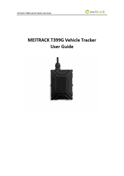
MEITRACK T399G Vehicle TrackerUser GuideChange HistoryContents1 Copyright and Disclaimer........................................................................................................................................... - 5 -2 Product Introduction ................................................................................................................................................. - 5 -2.1 Product Features........................................................................................................................................... - 5 -2.1.1 LoRa communication ........................................................................................................................... - 5 -2.1.2 K211G Status Monitoring..................................................................................................................... - 6 -2.1.3 Harsh Acceleration/Braking Alert......................................................................................................... - 6 -2.1.4 GPS Data Filtering ................................................................................................................................ - 7 -2.1.5 Activating Output by Event .................................................................................................................. - 7 -2.1.6 Idling Detection.................................................................................................................................... - 8 -2.1.7 Changing I/O Port Mode ...................................................................................................................... - 8 -2.1.8 Auto Arming......................................................................................................................................... - 8 -2.1.9 Starting the Engine by RFID/iButton .................................................................................................... - 9 -3 Product Functions and Specifications........................................................................................................................ - 9 -3.1 Product Functions......................................................................................................................................... - 9 -3.1.1 Position Tracking .................................................................................................................................. - 9 -3.1.2 Anti-Theft............................................................................................................................................. - 9 -3.1.3 Other Functions ................................................................................................................................. - 10 -3.1.4 Functions of Optional Accessories ..................................................................................................... - 10 -3.2 Product Specifications ................................................................................................................................ - 10 -4 T399G and Accessories............................................................................................................................................ - 11 -5 Appearance.............................................................................................................................................................. - 12 -6 First Use................................................................................................................................................................... - 12 -6.1 Installing the SIM Card................................................................................................................................ - 12 -6.2 LED Indicator............................................................................................................................................... - 13 -6.3 Device Configuration .................................................................................................................................. - 13 -6.3.1 Installing the USB Driver .................................................................................................................... - 13 -6.3.2 Configuring Device Parameters by Meitrack Manager....................................................................... - 14 -6.3.3 Binding the K211G ............................................................................................................................. - 15 -6.3.4 Unbinding the K211G......................................................................................................................... - 15 -6.4 Tracking by Mobile Phone........................................................................................................................... - 16 -6.5 Common SMS Commands .......................................................................................................................... - 17 -6.5.1 Real-Time Location Query – A00........................................................................................................ - 17 -6.5.2 Setting Authorized Phone Numbers – A71 ........................................................................................ - 17 -6.5.3 Setting the Smart Sleep Mode – A73 ................................................................................................. - 17 -6.5.4 Controlling Output Status – C01 ........................................................................................................ - 18 -6.5.5 Setting I/O Port Status – C08 ............................................................................................................. - 18 -6.5.6 Setting Idling Time – D34 ................................................................................................................... - 19 -7 MS03 Tracking System ............................................................................................................................................. - 20 -8 Installing the T399G................................................................................................................................................. - 20 -8.1 Installing an I/O Cable................................................................................................................................. - 20 -8.1.1 Interface Definition............................................................................................................................ - 20 -8.1.2 Wiring Diagram .................................................................................................................................. - 21 -8.1.3 Setting Code Matching of the RF Remote Control ............................................................................. - 23 -8.2 Mounting the T399G................................................................................................................................... - 24 -1Copyright and DisclaimerCopyright © 2019 MEITRACK. All rights reserved.and are trademarks that belong to Meitrack Group.The user manual may be changed without notice.Without prior written consent of Meitrack Group, this user manual, or any part thereof, may not be reproduced for any purpose whatsoever, or transmitted in any form, either electronically or mechanically, including photocopying and recording.Meitrack Group shall not be liable for direct, indirect, special, incidental, or consequential damages (including but not limited to economic losses, personal injuries, and loss of assets and property) caused by the use, inability, or illegality to use the product or documentation.2Product IntroductionThe T399G is a multi-purpose vehicle tracker. It not only can be used for tracking and positioning, but also used for K211G GPS smart lock management. It has an ability to monitor and record K211G status in real time, and to systematically manage the connection status, battery power and alerts of the K211G. This unit features an IP67 water resistance rating, is equipped with built-in GPS and GSM antennas, and can work in different environments. When it works with the K211G, it can be installed into trailers and box trucks. When it works alone, it can be installed into cars, motorcycles, yachts, boats, etc.2.1Product Features2.1.1LoRa communicationThis function is used for communication between the T399G and the K211G GPS smart lock. After the LoRa connection is successful, the K211G will send information such as lock status information, alert events and battery power to the T399G via LoRa. Then the T399G will upload K211G status information to the server at specific interval via GPRS network and will monitor the K211G status in real time.2.1.2K211G Status Monitoring2.1.3Harsh Acceleration/Braking AlertYou can detect the harsh acceleration/braking alert by setting the limit value. Cautions on device installation:1.The device should be installed into the vehicle according to the following direction.2.The device installation angle cannot exceed 15 degrees.The default harsh acceleration and braking alert values are 230 mG and -300 mG respectively.Note: The alert results vary according to the device installation, vehicle model, vehicle weight, and driving behaviors. After the device has been installed properly, you can use the Meitrack Manager software to adjust the harsh acceleration and braking alert values by every 10 mG. You can also use the D79 command to set the values.2.1.4GPS Data FilteringThe GPS data filtering function can ensure GPS data accuracy and eliminate static drift.You can set the following parameters by Meitrack Manager: GPS speed range, GPS positioning accuracy, and Number of GPS satellites. When the GPS data filtering function is enabled, if all conditions are met, GPS data will be updated.Note: This function can be enabled by Meitrack Manager.2.1.5Activating Output by EventYou can activate output by event.For example:1.When speeding is detected, the device can control buzzer sounds.2.When unauthorized ignition or GPS antenna cut-off is detected, the engine will not be able to start.3.When iButton triggering is detected, the device can control engine startup.4.When input or output status is detected, the output will be active or inactive.2.1.6Idling DetectionThis function is used to detect whether a vehicle's engine is switched off while parking. To enable the function, you must connect input 2 to ACC detection.When the device detects that the driving speed is 0 and the ACC is on for one consecutive minute (default time), an idling alert will be generated.For details, see section 6.5.6 "Setting Idling Time – D34."2.1.7Changing I/O Port ModeThis function is used to change the I/O port mode. For example, change active negative input to analog port or positive input.For details, see section 6.5.5 "Setting I/O Port Status – C08."2.1.8Auto ArmingYou can enable the auto arming function by B27 command, Meitrack Manager software or MS03 tracking platform. This function is disabled by default.When the device is in sleep mode and the function has been enabled, the device will enter auto arming state.You can set disarming by B21 command or remote control.Note:1.To implement the fuel/power cut-off function for a vehicle theft alert, you should select the vehicle theft eventin the Output 1 column on the Meitrack Manager software.2.To implement the alert function of the buzzer, you should set the 1-Wire interface (green cable) to alert output.2.1.9Starting the Engine by RFID/iButtonAfter swiping the authorized RFID card or the authorized iButton key touches the iButton reader, the driver must start the engine within 1 minute. Otherwise, the tracker's output 1 will be triggered (engine cut-off), and thus the driver cannot start the vehicle. At the moment, if you want to start the engine, you must swipe the iButton key/RFID card again.Before starting the engine, ensure that:1.The tracker's input 2 is connected to the engine detection cable.2.An iButton key or RFID card has been authorized.3.The tracker's output 1 is connected to the engine control cable through a relay.4.The RFID ignition function has been enabled by Meitrack Manager or MS03 tracking platform.5.The RFID event has been enabled on Meitrack Manager.3Product Functions and Specifications3.1Product Functions3.1.1Position Tracking●GPS + LBS positioning●Real-time location query●Tracking by time interval●Tracking by distance●Tracking by mobile phone●Speeding alert●Cornering report3.1.2Anti-Theft●Polygonal geo-fence alert●Engine or vehicle door status alert●Remote vehicle fuel/power cut-off●GPS blind spot alert●Towing alert3.1.3Other Functions●SMS/GPRS (TCP/UDP) communication●Built-in 8 MB buffer for recording driving routes ●IP67 water-resistance rating●Mileage report●Roaming parameter settings●Smart sleep mode●Built-in 3-axis accelerometer●Online Parameter Editor●GPS data filtering●Activate output by event●Stop Moving and Start Moving alerts●Vehicle power protection●Idling alert●AGPS3.1.4Functions of Optional Accessories3.2Product Specifications4T399G and AccessoriesT366G and standard accessories:●T366G tracker (with a cable of 50 cm in length) ●400 mAh battery (-20°C to 60°C)●L wrench●Hexagon screw●CD download card5Appearance6First Use6.1Installing the SIM Carde the screwdriver to open the back cover.SIM card slot Firmware upgrade button Power buttonGSM indicator USB portGPS indicator2.Insert the SIM card into the card slot (card chip facing down).3.Close the cover, and tighten the screws.Note:●Power off the device before installing the SIM card.●Ensure that the SIM card has sufficient balance.●Ensure that the phone card PIN lock has been closed properly.●Ensure that the SIM card in the device has subscribed the caller ID service if you want to use your authorizedphone number to call the device.6.2LED IndicatorPress and hold down the power button for 3–5 seconds to start the device.6.3Device Configuration6.3.1Installing the USB Driver1.Decompress the stsw-stm32102.zip file provided by Meitrack, locate the following file, and install the USBdriver on a computer with 64-bit Windows system.2.After the installation is finished, connect the tracker to the computer by USB cable. If STMicroelectronicsVirtual COM Port (COM5) is displayed on the Computer Management page, the driver is installed successfully.Note: Before connecting the device to the computer by USB cable, turn on the device first. Otherwise, it cannot be detected by Meitrack Manager.Note: After you finish the driver installation, if the preceding figure is not displayed, copy the mdmcpq.inf file to the c:/windows/inf/directory and usbser.sys file to the C:/windows/system32/drivers/directory. Then restart the computer.6.3.2Configuring Device Parameters by Meitrack ManagerThis section describes how to use Meitrack Manager to configure the device on a computer.Operation steps:1.Install the USB driver and Meitrack Manager.2.Connect the device to a computer by using the USB cable.3.Run Meitrack Manager (6.0.0.9 version or later), then the following dialog box will appear:4.Turn on the device, then Meitrack Manager will automatically detect the device model and the parameter pagewill appear accordingly.For details about Meitrack Manager, see the MEITRACK Manager User Guide.6.3.3Binding the K211GTo make the T399G and K211G communicate with each other via LoRa, bind the two devices. After the binding is successful, the T399G can communicate with multiple K211G devices, and will upload lock status information and alerts of multiple K211G devices to the server.Perform the following steps to bind the K211G:1.Go to the Peripheral page of Meitrack Manager.2.Enter the IMEI number of the K211G.3.Click Binding.4.Click Set.After the binding is successful, the IMEI number of the K211G will displayed on the Head Tracker Information area.6.3.4Unbinding the K211GThis operation is used to disconnect the communication between the T399G and the K211G. After the unbinding is successful, the T399G will not obtain status information and alerts of the K211G.Perform the following steps to unbind the K211G:1.Go to the Peripheral page of Meitrack Manager.2.Select the IMEI number to be unbounded.3.Click Unbind.4.Click Set.6.4 Tracking by Mobile PhoneCall or send the 0000,A00 command by SMS to the device's SIM card number. The device will reply to an SMS with a map link.Click the SMS link. The device's location will be displayed on Google Maps on your mobile phone.Note: Ensure that the device's SIM card number has subscribed the caller ID service. Otherwise, the tracking function by mobile phone will be unavailable.SMS example:Now,061314 10:36,V,26,0Km/h,96%,/?lat=22.513781&lng=114.057183 The following table describes the SMS format:If your mobile phone does not support HTTP, enter the latitude and longitude on Google Maps to query a location.6.5Common SMS Commands6.5.1Real-Time Location Query – A00SMS sending: 0000,A00SMS reply: Now,Date and time,Positioning status,GSM signal strength,Speed, Remaining battery power,Map link Description: This command is used to query tracker's current location.Example:Sending: 0000,A00Reply: Now,160721 16:40,V,12,56Km/h,97%,/?lat=22.513015&lng=114.0572356.5.2Setting Authorized Phone Numbers – A71SMS sending: 0000,A71,Phone number 1,Phone number 2,Phone number 3SMS reply: IMEI,A71,OKDescription:Phone number: A phone number has a maximum of 16 bytes. If no phone numbers are set, leave them blank. Phone numbers are empty by default.Phone number 1/2/3: Set these phone numbers to authorized phone numbers. When you call the tracker by using these phone numbers, you will receive SMS notification about the location, geo-fence alert and low power alert and SMS notification or a call about the unauthorized door open and unauthorized ignition.If you need to delete all authorized phone numbers, send 0000,A71.Example:Sending:0000,A71,138****1111,138****2222,138****3333Reply: 353358017784062,A71,OK6.5.3Setting the Smart Sleep Mode – A73SMS sending: 0000,A73,Sleep levelSMS reply: IMEI,A73,OKDescription:When the sleep level is 0, the sleep mode is disabled (default).When the sleep level is 1, the tracker enters the normal sleep mode. The 3G module always works, and the GPS module occasionally enters the sleep mode. The tracker works 25% longer in the normal sleep mode than that in the normal working mode. This mode is not recommended for short interval tracking; this will affect the route precision. When the sleep level is 2, the tracker enters the deep sleep mode. If no event (SOS, button changes, incoming calls, SMSs, or vibration) is triggered after five minutes, the GPS module will stop working, and the 3G module will enter sleep mode. Once an event is triggered, the GPS and 3G modules will be woken up.Note: In any condition, you can use an SMS command to disable the sleep mode, and then the tracker exits the sleep mode and returns back to the normal working mode.Example:Sending: 0000,A73,2Reply: 353358017784062,A73,OK6.5.4Controlling Output Status – C01SMS sending: 0000,C01,Speed,ABCDESMS reply: IMEI,C01,OKDescription:When the speed is 0, no speed limit exists. That is, when the tracker receives a command, the output control takes effect immediately.When the speed is a value ranging from 1 to 255 (unit: km/h), set the speed limit for output control. When the driving speed is lower than the speed limit, the output control takes effect.ABCDE: indicates the output 1, output 2, output 3, output 4, and output 5 respectively. When the parameter value is 0, the output is disabled. When the parameter value is 1, data will be generated according to preset output mode. When the parameter value is 2, previous status will be remained.Example:Sending: 0000,C01,10,10000Reply: 353358017784062,C01,OK6.5.5Setting I/O Port Status – C08SMS sending: 0000,C08,IO0:Mn,IO1:Mn,IO2:Mn,IO3:Mn,IO4:MnSMS reply: IMEI,C08,IO0:Mn,IO1:Mn,IO2:Mn,IO3:Mn,IO4:MnDescription:1.IO0, IO1, IO2, IO3, and IO4 indicate I/O ports.IO0: open collector 1 by default (yellow cable)IO1: 1-Wire interface by default (green cable)IO2: negative input 1 by default (grey cable)IO3: positive input 2 by default (white cable)IO4: AD input 1 by default (blue cable)2.Mn indicates the I/O port status. The parameter value is as follows:0: low trigger1: high trigger2: AD input3: Remote control input4: open collector5: low output6: PWM output7: Buzzer alert output8: 1-Wire3.You can set one or multiple input ports at the same time. The command 0000,C08 is used to read I/O portparameters.Note:1.IO0: Mn parameter value is 4, 5, or 6.2.IO1: Mn parameter value is 0, 4, 5, 7, or 8.3.IO2: Mn parameter value is 0, 1, or 2.4.IO3: Mn parameter value is 0, 1, or 2.5.IO4: Mn parameter value is 0, 1, 2, or 3.Example:Sending: 0000,C08,IO0:5Reply: 353358017784062,C08,IO0:5,IO1:0,IO2:2,IO3:2,IO4:16.5.6Setting Idling Time – D34SMS sending: 0000,D34,TimeSMS reply: IMEI,D34,OKDescription:Time: When the device detects that the driving speed is 0 and the ACC is on (input 2 activated) for consecutive several minutes, an idling alert will be generated.Value range: 0–65536; unit: minute; default value: 1 minuteExample:Sending: 0000,D34,1Reply: 353358017784062,D34,OKFor details about SMS commands, see the MEITRACK SMS Protocol.Note:1.The default SMS command password is 0000. You can change the password by using Meitrack Manager andSMS command.2.The device can be configured by SMS command with a correct password. After an authorized phone number isset, only the authorized phone number can receive the preset SMS event report.7MS03 Tracking SystemVisit , enter the user name and password, and log in to the MS03. (Purchase the login account from your provider.)For more information about how to add a tracker, see the MEITRACK GPS Tracking System MS03 User Guide (chapter 4 "Getting Started").The MS03 supports the following functions:●Track by time interval or distance.●Query historical trips.●Set polygonal geo-fences.●Bind driver and vehicle information.●View various reports.●Send commands in batches.●Support OTA updates.For details, see the MEITRACK GPS Tracking System MS03 User Guide.8Installing the T399G8.1Installing an I/O Cable8.1.1Interface DefinitionThe I/O cable is an 8-pin cable, including the power, analog input, and negative/positive input and output interfaces.The I/O cable of T399G RS232 version is an 11-pin cable. Besides the above 8 pins, there are the following 3 pins.8.1.2Wiring DiagramT399G standard version:T399G RS232 version:8.1.3Setting Code Matching of the RF Remote ControlAfter the cover of the remote control receiver is removed, there will be a purple cable, as shown in the following figures.Remove the coverPerform the following steps to set code matching:1.Connect the remote control receiver's yellow cable to 5 V power supply and code matching cable (purple) toGND for more than 2 seconds.2.Press any key of the remote control, and then press any key of the other remote control.3.Release the code matching cable of the remote control receiver.4.Enable the SMS/GPRS events of arming and disarming, and use the remote control to set arming or disarming.If an SMS or GPRS event is received, the code matching is set successfully.Definitions of RF Remote Control Keys:Arm keyNote: The buzzer connects to the 1-Wire interface (green cable), which needs to be set to output 2.8.2Mounting the T399GMount the device in the vehicle by cable tie.Note: Do not install it at a metal covered place.Ifyouhaveanyquestions,*****************************************.。
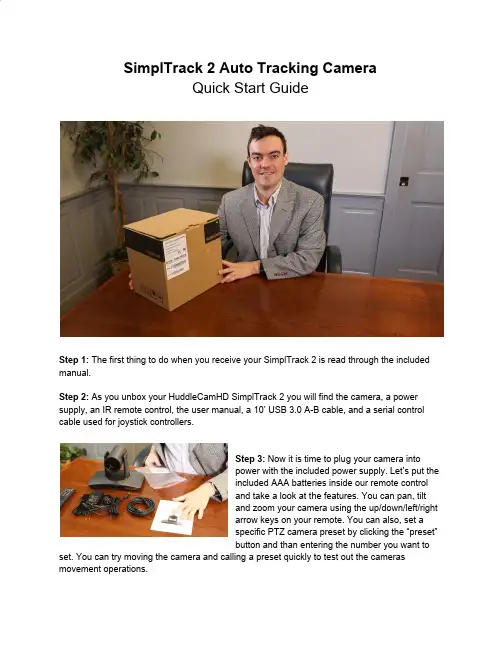
SimplTrack 2 Auto Tracking CameraQuick Start GuideStep 1:The first thing to do when you receive your SimplTrack 2 is read through the included manual.Step 2:As you unbox your HuddleCamHD SimplTrack 2 you will find the camera, a power supply, an IR remote control, the user manual, a 10’ USB 3.0 A-B cable, and a serial control cable used for joystick controllers.Step 3:Now it is time to plug your camera intopower with the included power supply. Let’s put theincluded AAA batteries inside our remote controland take a look at the features. You can pan, tiltand zoom your camera using the up/down/left/rightarrow keys on your remote. You can also, set aspecific PTZ camera preset by clicking the “preset”button and than entering the number you want to set. You can try moving the camera and calling a preset quickly to test out the cameras movement operations.Note: In order to configure the camera, you will need to connect the camera to a live network feed from a network with a DHCP server. Once the camera is turned on and connected to the network we can install the HuddleCamHD SimplTrack control software.Step 4:You can download the HuddleCamHD SimplTrack control software from /ResourcesNote:This software is only available for Windows. Therefore a Windows computer will be required for initial setup of this cameraStep 5:Once the software is installed on your computer, make sure your computer is connected to the same network as the camera. The software should automatically recognize your SimplTrack camera on the network. You can simply double click the camera in your camera list to start configuration.Step 6: You may want to connect your camera to a meeting room computer or in room display. You can connect the camera to a computer using the USB 3.0 output, to any standard televisionusing a DVI to HDMI cable, and to an SDI monitor using a standard SDI cable.Note: The camera features auto resolution & frame rate conversion upon connecting to a video conference software via USB. The camera may auto power cycle in order to reset the camera resolution to match your connected source.Step 7: Let’s review the software interface and configure your SimplTrack. The main interface offers the ability to interact with the basic features of the camera not directly relating toauto-tracking in addition to providing a live preview. Clicking the magnifying glass in the Camera List section will show the available auto tracking cameras on a network. Simply double click on an available camera to connect. Under Lens Control, standard controls are available for Zoom (Tele / Wide), Focus (Near / Far), Iris (Open / Close), and Iris Reset. The Presets section will Set, Call, and Clear Presets 0-255.Note : Preset 1 is used as a reference for framing your tracking subject and Preset 0 is typically used for framing your stage / podium. This is how you tell the camera how much space you want around your subject during the auto-tracking mode.Step 8:The PTZ Controls section serves two functions: first, to provide manual Pan and Tilt controls, the other is to control the OSD using the Menu button. You can start and stop the cameras auto-tracking capabilities at any time using the Start and Stop buttons under Tracking Control. But before we turn on the auto-tracking let’s set some parameters that will ensure seamless operation.Note:Use the “Iris+” button within the OSD to choose options, and “Iris-” to go back a field.Step 9:Let’s click the “Settings” button at the bottom right of this application. When entering the Advanced Parameters settings interface, the live preview will switch to a split-screen showing the images from both the reference camera and the tracking camera. This is where all features relating to auto-tracking can be setup. Under the Basic Settings section, the SDI & DVI Output resolution and frame rate can be set in addition to protocol settings for the RS-232 connection. Clicking Set in the Tracking Zone section will allow you to draw a green rectangle to define a priority tracking area. Within the Tracking Zone you can set Blocking Zones. These are areas that the camera will ignore motion within, such as a doorway with people walking by or an LCD screen with active video content displayed. Note that the Blocking Zones must be used within the Tracking Zone. Tracking Setting will define what actions the camera is allowed to perform. Use Auto-Tilt when your subject will be walking towards and away from the camera. Free track is used to track a ny moving object regardless of being within the defined tracking zone. Use Permanent Track if your presenter walks outside of the defined tracking zone. Enable Auto Zoom to allow the presenter to move freely beyond the Object Lost reference position. AutoZoom is also affected by the Zoom Limit slider.Step 10:Use the Tracking Parameters section to cater the tracking for your room & presenter. Tracking sensitivity defines how much motion is required from the subject to trigger the tracking capabilities. The higher the sensitivity, the less motion is required. Pan & Tilt Speed allows customization over the speed at which the camera tracks. Set the Zoom Limit to define the maximum distance the camera will auto zoom. Set the Lost Timeout to set when the camera will automatically go back to the reference preset after the presenter is lost.Step 11:The Object Lost Action tells the camera to go to Preset 0, Preset 1 or to Stay when the presenter is lost by the camera. For best results, set the Object Lost Action to the full “stage”, which allows the camera to find the presenter and start tracking again.Note:When adjusting the settings of the SimplTrack, be sure to click Save, then OK to save the current settings.Note: W hen working with multiple SimplTrack systems you can ensure you are working on live settings for each camera by clicking the Inquire button to query the connected camera for its current settings. If you have multiple cameras on your network you may want to change the cameras name in the configuration area.Note:To pull the main RTSP stream please use the following URL rtsp://:/main.h264 (example: rtsp://192.168.111.85:5000/main.h264) Note: To pull the sub RTSP stream please use the following URL rtsp://:/sub.h264 (example: rtsp://192.168.111.85:5000/sub.h264)Step 12:You have now set up your SimplTrack and configured the auto-tracking capabilities towork in your environment. Remember if you have any questions during your setup process youcan always call our support team using the phone number listed on our website. You can also submit a support ticket at any time at . Enjoy!。


Thank you for purchasing the Chandler Limited Little Devil Pre Amp. Your Devil is handmade in the USA by real people. What does that mean? We do not use large solder or component machines that pick and solder the parts. We pay a real person to do it like they did in the golden age of gear. We do not have most of our work done in China only to do nal assembly in America and then call it made in USA. We do not use surface mount components or ribbon cables that have been recently developed to shrink the size and build time of cell phones and computers. Instead we use time proven through-hole audio components, discrete transistors, and large transformers just like they did in the golden age of gear.At Chandler we are proud of our American made products and we hope you like them!The Little Devil Pre uses a 100% discrete transistor circuit and specially wound transformers. Included are item descriptions and hints to get you on your way.Please feel free to call our shop anytime for help or questions.Prior to sending in your gear for repair, please contact our shop at the number listed below. We will assist you in troubleshooting the problem and, if needed, we will issue you an RMA# to send in the gear.Send repairs to: Chandler Limited, Inc. Attention: Repairs 222 S. Cherry St.Shell Rock, IA 50670Phone: (319) 885-4200Email:*************************** Connections - All connections on the Devils are transformer balanced with pin 2 hot.Current draw -Here are the current draw speci cations for the Little Devil Preamp when the Devil is loaded 600 ohm and operating at a continuous level of unity gain. Please consult your rack and PSU speci cations to make sure you are not overloading your system.+16 volt power rail = +95ma -16 volt power rail = -70maLittle Devil Pre Amp - Designed by Wade Chandler GoekeChandler Limited, Little Devil and the Little Devil Flame Logo are trademarks of Chandler Limited Inc.All rights reserved.COMPATIBILTY-The Little Devil Pre is tested and proven to have no start up or power errors in these racks-API 500v 10-slot with L200 PSUAPI 500-6B LunchboxAPI 500-6B HC “new version” LunchboxBAE 11-slot with power one supplyBAE 6-slot portable with power one supplyBAE 6-slot with Avedis designed supplyEmperical Labs 2-slot (awesome rack and worth the money!)A-Designs 2-slotPurple Sweet 10As of the release of this product we have not yet tested with the Radial Workhorse.POWER SUPPLY RECOMMENDATIONS-With ANY 500 modules (not just the Devils) we recommend using a rack with external supply. We feel a power supply in such close proximity to the right hand slots of the rack can cause hum and noise oor issues with many modules by many manufacturers. For this reason we mainly recommend the API 500v rack with external L200 supply and the BAE 11-slot with external supply.NOTES on BAE racks-We recommend adding a wire from Earth to power supply common on all BAE racks. In many cases hum can be avoided and Earth to common is standard procedure on most electronic equipment.GAIN - max gain 66.5 MIC/LINE- There are three di erent input types on the Devil 500. Mic/line switchesLOW/HIGH- Selects low or high impedance for BOTH mic and line freq response.FEEDBACK/BIAS-bias of the gain stage AT THE SAME TIME as the feedback. So what does this mean?Well you can modify about any parameter of the sound of the pre with the use of the feedback/bias control. It will change the frequency response in the hi and low areas, harmonic distortion, nature of clipping, and the overall tonal characteristic of the pre amp. For example with the feedback on full the sound gets “gushy” as users have described. The unit will soft clip much earlier, harmonics increase exponentially, hi frequency is slightly increased and the unit takes on a very high voltage “overbiased” Class A personality.With the feedback control low you get a very colored but more “tame” sound. Harmonics are very low (in the range of .007%) and noise is the lowest possible with the unit, in the area of -93db. The sound could be described as an accurate but interestingly colored Class A sound.With the Feedback/Gain near the middle of its operation you will get the most headroom and what could be considered the most typical operation of a mic pre. All parameters tend to come into the norm for a Class A style mic pre, BUT don't let that keep you from using it set there! The pre always has a great colored sound we all look for!Feedback continued on next page. . .IMPEDANCE LINEfeedback& biasNOTES ON FEEDBACK-With the feedback all the way down you will not get much level. This is the nature of feedback. Lots of feedback = very little gain. I wanted it like that because there are very speci c sounds you can get with it. For example, with lots of feedback (control o or counter clockwise)you get very little distortion and the noise oor is very low. It also allows you to use the pre with almost no gain for when you are recording loud sources like drums and guitar.Control o or counter clockwise- Lots of feedback, Little gain.Control full or clockwise- Very little feedback, lots of gain.pres with this feature, headroom of the pre is decreased as you lower the signal butwith the added bene t of a lower noise oor. The Devil pre loves to be driven so try this out! BRIGHT-LOW CUT-Gently sloping low cut at 100hz. We tuned this to work as needed with instruments such as acoustic guitar and voice.much di erent than that on readily available direct boxes. Please note that it is possible to make the DI oscillate with the Gain and Feedback/Bias at or near maximum. We did not compensate for this because it would alter the overall tone of the pre amp. In standard Mic or Line input it is not possible to cause oscillation.PHASE-Reverses the output polarity of the unit at the output transformer.DIRECT INoutputMIC48vCE CertificationChandler Limited declares under its sole responsibility that all products manufactured by them are in compliance with EC directives 2004/108/EC Electromagnetic Compatibility; 2004/108/EG Electromagnetic Compatibility; 2006/95/EC Low Voltage Equipment Safety.。
G P S T R A C K E R追踪王(GPS+AGPS+LBS+GSM+SMS/GPRS)使用指南(版本V1.0)非常感谢你选择使用GPS TRACKER追踪王,使用指南将详细的说明如何操作本产品。
请你在使用之前认真阅读使用指南,以便得到正确使用方法。
如有更改,恕不另行通知,每次更改将统一在最新的一次产品销售中发布,制造商对于使用指南中的过失和疏漏不承担法律责任。
目录1.产品简介2.应用领域3.规格描述4.产品配件5.使用说明5.1 SIM卡的安装和设备启动5.2设备充电5.3主控号码设置5.4单次定位5.5基站定位5.6中文地址查询5.7 SOS紧急求救5.8远程监听5.9震动报警5.10位移报警5.11电子围栏5.12超速报警5.13低电报警5.14睡眠省电模式设置5.15设防/重启和恢复出厂设置5.16 查询设备状态6.监控平台应用7.故障排除8.保修1.产品简介GPS TRACKER追踪王融合了GSM无线通信技术及GPS全球定位系统技术,采用工业级防火材料,6颗18MM×3MM强磁装置,IPX-5防水等级设计,内置8000MAH 大容量电池,超长待机100天,通过短信和全球定位服务平台实现对远程目标进行定位和监控管理。
强磁免安装设计,简单易用。
2.应用领域●汽车租赁/小型车队管理●户外活动●儿童/老人/残疾人士/贵重物品的监护●个人安全●人员管理●跟踪定位●动物保护和放牧3.规格描述4.产品配件●5V 1000MA充电器一个●充电线一条●使用指南和保修卡一本●GPS TRACKER追踪王设备一台5.使用说明5.1 SIM卡的安装和设备启动5.1.1 打开包装盒,检查设备型号是否正确,配件是否齐全,否则请联络你的经销商;5.1.2 SIM卡选择,设备需要插入一张GSM SIM卡,GSM卡联通或移动任选(GSM 网络全球通用)5.1.3 SIM卡的安装,拆开设备防水塞,依据标示,SIM卡芯片朝下插入卡槽,盖上防水塞。

.球形摄像机使用说明书V1.0版本简体中文板.目录目录 (1)第1章产品概述 (3)1. 1产品简介 (3)1. 2性能特点 (3)1. 3 功能说明 (4)1. 4 技术参数 (7)第2章球形摄像机的基本操作 (9)第3章菜单的设置 (11)3. 1 主菜单 (12)3. 2系统信息菜单 (13)3. 3 显示设置菜单 (14)3.3.1显示信息设置菜单 (14)3.3.2标志位置菜单 (15)3. 4 球机设置1菜单 (16)3.4.1球机设置1菜单 (16)3.4.2镜头设置菜单 (17)3.4.2.1自动曝光控制菜单 (18)3.4.2.2其它菜单 (21)3.4.3云台设置菜单 (24)3.4.3.1 设置区域扫描范围的操作 (25)3.4.3.2 清除区域扫描范围的操作 (26)3.4.3.3 设置手动限位操作 (27)3.4.3.4设置水平方位角为0度操作 (28)3.4.3.5清除0度水平方位角操作 (28)3.5上电设置菜单 (29)3.6预置点设置菜单 (30)3.6.1编辑预置点标题 (30)3.6.2编辑预置点位置 (33)13.6.3清除此预置点设置 (33)3.7花样扫描菜单 (34)3.7.1花样扫描设置 (35)3.7.2清除此花样扫描路线 (35)3.8区域设置菜单 (36)3.8.1編輯区域标题 (37)3.8.2编辑区域 (37)3.8.3打开和关闭此区域 (38)3.8.4清除此区域标题 (38)3. 9 清除设置菜单 (39)3. 10 球机设置2菜单 (40)3.10.1 球机设置2菜单 (40)3.10.2报警输入设置菜单 (40)3.10.3 报警设置菜单 (41)3.10.4清除报警设置 (43)3.10.5 报警输出设置 (43)3.10.6 密码设置菜单 (44)3.10.7 密码输入菜单 (45)3.10.7 屏幕遮挡菜单 (46)3.10.8 屏幕遮挡设置菜单 (47)3.10.9 编辑屏幕遮挡区域菜单 (48)3.10.10 编辑屏幕遮挡放大倍数菜单 (49)3.10.11 加热控制菜单 (50)3.10.12 巡航设置菜单 (51)3.10.13跟踪控制菜单 (52)3.10.14跟踪区域控制菜单 (54)3.11 球机标题菜单 (55)3.12 语言选择 (55)附录一型号说明 (56)2第1章产品概述1. 1产品简介VT系列球形摄像机是采用当今最新的科技成果、最精尖的制造工艺;综合多年的宝贵经验研制成功的,配置了自动变焦镜头的高性能数字信号处理(DSP)CCD;集内置云台和数字解码器于一体,代表新一代高技术监控产品的发展潮流。

About the T utorialMantis is a Bug Reporting tool, widely used as an issue tracking tool for all types of testing. This is a brief tutorial that introduces the readers to the basic features and usage of Mantis. The various chapters of this tutorial will guide the readers on how to utilize the tool in reporting and maintain an issue.AudienceThis tutorial has been prepared for beginners to help them understand how to use Mantis for testing and issue tracking.PrerequisitesAs a reader of this tutorial, you should have a basic understanding of a bug and testing lifecycle as well as the contents to provide in a bug.Copyright &DisclaimerCopyright 2018 by Tutorials Point (I) Pvt. Ltd.All the content and graphics published in this e-book are the property of Tutorials Point (I) Pvt. Ltd. The user of this e-book is prohibited to reuse, retain, copy, distribute or republish any contents or a part of contents of this e-book in any manner without written consent of the publisher.We strive to update the contents of our website and tutorials as timely and as precisely as possible, however, the contents may contain inaccuracies or errors. Tutorials Point (I) Pvt. Ltd. provides no guarantee regarding the accuracy, timeliness or completeness of our website or its contents including this tutorial. If you discover any errors on our website or in this tutorial,******************************************T able of ContentsAbout the Tutorial (i)Audience (i)Prerequisites (i)Copyright &Disclaimer (i)Table of Contents (ii)1.MANTIS ─ INTRODUCTIO N (1)2.MANTIS ─ FEATURES (3)3.MANTI S ─ INSTALLATION (5)System Requirements (5)Installation of System Requirements (5)Install and Launch Mantis (11)4.MANTIS ─ TRIAL SETUP (16)Setup for Demo Trial (16)5.MANTIS – LOGIN (18)On Error (19)On Successful Login (20)6.MANTIS ─ MY VIEW (21)7.MANTIS ─ PROJECT MAN AGEMENT (23)Create a Project (23)Select a Project (25)Archive a Project (25)8.MANTIS ─ MANAGE CATEGORIES (27)Create a Category (27)Configure Categories (28)Delete a Category (29)9.MANTIS ─ VERSIONS (31)Update or Add Version (31)10.MA NTIS ─ ISSUE LIFECYC LE (33)11.MANTIS ─ REPORT AN I SSUE (34)12.MANTIS ─ IMPORT ISSU ES (37)Rules for CSV File (37)Import CSV (37)13.MANTIS ─ VIEW ISSUES (42)Filters (42)Print Reports (45)CSV/Excel Export (47)14.MANTIS ─ EDIT ISSUES (49)15.MANTIS – CLONE AN ISSUE (53)16.MANTIS – ADVANCED FEATURES (56)@Mention – Notification (56)Send Reminder (57)Text Formatting (59)Attach Files (59)17.MANTIS – CHANGE STATUS (61)18.MANTIS – ISSUES RELATIONSHIPS (63)Create a Link to Another Issue (63)Delete a Link (64)19.MANTIS – MOVE AN ISSUE (66)One Issue At a Time (66)Multiple Issues at a Time (67)20.MANTIS – ISSUE HISTORY (68)21.MANTIS – MISCELLANEOUS FUNCTIONALITIES (70)Monitor (70)Stick (71)Close an Issue (73)Delete an Issue (75)22.MANTIS – SEARCH ISSUES (77)Search (77)Recently Visited (78)23.MANTIS – CHANGE LOG (79)24.MANTIS – ROADMAP (81)25.MANTIS ─ SUMMARY (83)26.MANTIS – ADD CUSTOM FIELDS (84)Mantis Bug Tracker is an open source web-based application tool. It is used for Bug Tracking throughout Defect Lifecycle. Along with bug tracking, Mantis supports Release Features to manage various releases of a project or a software.Mantis is also known as MantisBT, which stands for Mantis Bug Tracker. The name and logo of Mantis refers to Mantidae family of insects. In software, it is referred to as a bug.Mantis provides Demo, Download (to set up your own Mantis) and Hosting version of the tool. It supports various features for Issue Tracking and life cycle along with Release Management. The development of Mantis started in 2000 by Kenzaburo Ito. Later in 2002, other team members (Jeroen Latour, Victor Boctor and Julian Fitzell) joined. The basic version 1.0.0 of Mantis was released in February 2006.In 2012, GitHub became the official repository for the Mantis project source code.License and Free Trial∙It is an open source software. License is not required to use its basic version.∙It provides Demo and Hosting Version for free trails.∙It supports Download feature to set up your own Mantis software.The user can sign up using email ID.∙Mantis has different price quotes based on added features that can be seen at https:///pricingUsage∙To track all bugs/issue throughout Defect lifecycle.∙To manage at Release level as well.∙Supports Analytic and Reporting features.∙Supports plug-in with other softwares and IDE to make it more strong and effective. SpecificationsMantisMantis supports a wide range of features to attract QAs and other stakeholders for bug tracking. Following are the core features of Mantis.Core FeaturesMantisMantis is a web application, provides a private website to individuals or set of requested users belonging to the same company/project.Mantis can be run at the server side. It is a PHP-based application and supports all OS platforms such as Windows, Linux of different versions, MAC, etc. It supports mobile browsers as well in mobile views.System RequirementsSince Mantis is a web-application, it follows the concept of client/server. This means, Mantis can be installed centrally on the server and users can interact with it through web-browsers using a website from any computer.∙Web Server: Mantis is tested with Microsoft IIS and Apache. However, it can work with any latest web server software. Mantis only uses .php file. Configure the web server with .php extension only.∙PHP:The web server should support PHP. It can be installed as CGI or any other integration technology.∙Mandatory PHP Extensions: Extensions for RDBMS are mysqli, pgsql, oci8, sqlsrv mbstring is required for Unicode– UTF-8 support.∙Optional Extensions: Curl, GD, Fileinfo.∙Database: Mantis requires a database to store its data. MySQL and PostgreSQL are supported RDBMS.∙Client Requirements: Firefox 45 and above, IE 10 and above, Chrome, Safari, and Opera.Users can separately install all the requirements either manually or automatically to use Mantis.Installation of System RequirementsIf a user has adequate knowledge about the installation process, all the requirements can be installed one by one separately before proceeding to Mantis.Alternatively, there are many all-in-one packages available, having all the requirements and can be automatically installed in the system by exe file. Here, we will take the help of XAMPP to install pre-requisites easily.Step 1: Go to https:///index.html and click XAMPP for Windows as shown in the following screenshot.Step 2: A pop-up will display to save the file. Click Save File. It will start downloading the file.Step 3: Run the .exe file to run the installation wizard. After clicking the .exe file, XAMPP Setup wizard displays. Click Next.The following screenshot shows the XAMPP setup wizard.Step 4: The next wizard displays all the component files that will install as shown in the following screenshot. Click Next after making a selection of components.Step 5: Provide a folder name where XAMPP will be installed and click Next.Ready to Install wizard is displayed.Step 6: Click Next to start the installation.MantisEnd of ebook previewIf you liked what you saw…Buy it from our store @ https://。

Shipment Tracking for Magento 2Setup &User GuideAbout this documentThis document offers the basic knowledge for installing and using the ShipTracker extension for Magento 2.This document is copyrighted © 2018 – 2021 Athanasios Terzis / .The document is licensed under the terms of Creative Commons Attribution-NoDerivatives 4.0. license [https:///licenses/by-nd/4.0/] .This license allows for redistribution, commercial and non-commercial, as long as it is passed along unchanged and in whole, with credit to the copyright holder. If you require another use, please email the author in order to acquire such a license and the source to this document.About ShipTrackerThe ShipTracker extension offers automated shipment tracking based on the tracking codes which are saved in the Magento shop (Sales > Shipments). This happens by using 3rd party APIs, for shipment tracking.Also notifies the customer/recipient with an email, every time there is a change in the status of the shipment (Info Received, In Transit, Out for Delivery, Delivered, Failed Attempt, etc.).CompatibilityMagento Open Source 2.2.x, Magento Open Source 2.3.x, Magento Open Source 2.4.xInstallation (alternative to Marketplace installation) You are advised to install the extension following the Marketplace guidelines.The described process, can be used as an alternative in case you are facing issues, with the installation through the Marketplace.After downloading the package, please do the following:1.In your Magento’s installation, create the folder: app/code/Breakdesigns/ShipTracker2.Extract/Unpack the zip file, you downloaded.3.Upload the extracted files/folders to the folder you created(app/code/Breakdesigns/ShipTracker).4.Enable the module and update the database schema.In the terminal use the following commands:Enable the moduleUpdate the databaseDeploy static filesConfigurationGo to Stores > Configuration > Breakdesigns Extensions > ShipTrackerWeb API1. Select the service you are going to use as Web API.An active account with adequate credits is required, for the extension to work.2. Enter your API KeyThe Web Api services, provide an API key, to their users, for accessing their API.To get your API Key, you better address to your service's documentation and support.•Get AfterShip Api Key•How to get TrackingMore Api Key3. Set the period/days that you want a shipment, to be monitored (Shipments Monitoring Period). The maximum limit is 60 days.4. If your shop is already in production and has orders and shipments, you better limit our module tomonitor shipments (POST new shipments) created before some days, instead of monitoring all of them. This will spare credits and resources to your Web API service, for shipments that are possibly already delivered. For that you can use the setting, New Shipments Lookup PeriodEmailsWith these settings you can determine, when and which notification emails will be send to the customer/recipient.All the email templates, can be customized and overwritten as any email template in magento.For more details on that topic, please read Customize email templates using the Magento Admin.If you create your own customized email templates, you have to come back in this section and select your preferred template.UsageCheck the CarriersNow the module should normally perform most of it's tasks.Though there are cases that require some action.Go to ShipTracker > Carriers and click on the Sync Carriers button.*This page shows the carriers installed in the shop and is used as an interface between the shop's carriers and the web API’s carriers.This is the 1st call to the Web Api, hence it's a good chance to check if the configuration isproper and your web api account is functional. If there is any problem, you will get an error message.If you did not get any error, check if the used carrier codes are validated by the web API.What the validation process does, is to check if the carrier codes used in your shop, are the same as those used by the web tracking API service.If a code is not valid, you need to edit the carrier and set a valid carrie code, that will be used for the communication with the API.Before doing that you better visit the website of your selected web api (AfterShip, TrackingMore, etc.), to learn what are the codes they use for your carriers that seem invalid.You can easily determine a carrier code from the urls of the demo tracking pages relatedwith a carrier, provided by your web api service.e.g. https:///elta-courier/PS205923435GR indicates that the code for theHellenic Post is elta-courier.Beyond setting a web api code, you can edit a carrier to fill in information like a website, a telephone and a logo. These information will be used both in the notification emails and in the tracking page, provided to the user.Add Custom Carriers (Optional)In some cases, you may want to use carriers in your trackings without having the respected carrier modules installed in your shop.In such cases, you can create those custom carriers in ShipTracker. This way you can use them inyour trackings (Shipments>Orders).Go to ShipTracker > Carriers and click the Add Custom Carrier button.Then you have to fill in the respected formThe 2 most important fieldshere are:•Code > The carrier codethat used in your shop(as saved in the table sales_shipment_track)•Web Api Code > The carrier code that the web api uses for that carrier (see previous chapter).TrackingsThis is the page that the shop's admin can use to get informed about the status of a shipment.The Update Trackings button, can be used for deliberate/manual update of the trackings. Themodule automatically sends and fetches information about the trackings every 15minutes through cron jobs. Also the sending of notification emails is automated as well.DetailsBy clicking the details link, you can find details such as the Itinerary/History of the Shipment or the notifications sent to the recipient.I need more helpIf you got stuck and you need more help you can use our support services.If you purchased the extension from the Magento Marketplace, you can ask for support at********************************Support is only offered for the time period after the purchase, referred in the product’s page. After that period, the extension needs to be purchased again, to receive support.。
PC Software User ManualTopcon Ag AmericasW5527 Hwy 106Fort Atkinson, WI 53538USATel: 800-225-7695E-mail:*******************D3833-EN Harvest Tracker Rev DAll rights reserved. Reproduction of any part of this manual in any form whatsoever without Digi-Star’s express written permission is forbidden. The contents of this manual are subject to change without notice. All efforts have been made to assure the accuracy of the contents of this manual. However, should any errors be detected, Digi-Star would greatly appreciate being informed of them. The above notwithstanding, Digi-Star can assume no responsibility for errors in this manual or their consequence.© Copyright 2017 Topcon Ag Americas, Fort Atkinson (U.S.A.)D3833 EN Rev D 29 Jul 17Page 2Harvest Tracker Software ManualD3833Table of Contents1.0 INTRODUCTION ................................................................................................................. 3 2.0 USE AND SETUP ................................................................................................................ 3 2.0.1 Minimum PC Requirements .......................................................................................... 3 2.0.2 Setup ............................................................................................................................. 3 3.0 RETRIEVING DATA ............................................................................................................ 4 4.0 REPORTS ........................................................................................................................... 5 4.0.1 Report Screen Information ............................................................................................ 6 5.0 FIELDS ................................................................................................................................ 7 5.0.1 Fields Screen Information ............................................................................................. 8 6.0 ID’S ...................................................................................................................................... 9 6.0.1 ID’s Screen Information ............................................................................................... 10 7.0 CROPS .............................................................................................................................. 11 7.0.1 Crops Screen Information ........................................................................................... 12 8.0 FILE OPTIONS .................................................................................................................. 13 9.0 UTILITIES OPTIONS ......................................................................................................... 14 10.0 REPORTING OPTIONS .................................................................................................. 15 11.0 LANGUAGE OPTIONS .................................................................................................... 15 12.0 HELP OPTIONS .............................................................................................................. 16 13.0 REGISTRATION AND SYNCING WITH HARVEST TRACKER ON LINE ....................... 17 14.0 SOFTWARE LICENSE AGREEMENT . (18)Introduction1.0 INTRODUCTIONHarvest Tracker PC software is designed exclusively for use with Digi-Star GT460, GT465, and GT560 indicators used on Grain Carts, Weigh Wagons, and other harvest transport implements. Harvest Tracker PC software also works in conjunction with Digi-Star’s Harvest Tracker On-Line software.Harvest Tracker PC software is a utility software interface for GT460, GT465 and GT560 indicators. This software provides the following features:•Setup and manage “Fields” in Harvest Tracker and the Scale Indicator•Setup and manage “ID’s” and “Capacities” in Harvest Tracker and the Scale Indicator (GT560 Only)•Setup and manage “Crops” in Harvest Tracker and the Scale Indicator•Display, manage, produce reports, and export harvest data that is collected by the Scale Indicator.A USB drive with Harvest Tracker PC software is provided with each GT460, GT465, andGT560 indicator. Harvest Tracker PC software is also available as a free download from the Digi-Star website at the following location:/products/5/Software_and_Data_Transfer2.0 USE AND SETUP2.0.1 Minimum PC Requirements•Microsoft .NET 2.0 Framework or above•Microsoft Windows Vista SP2 or above•100 MB free disk space•500 MB Ram•Free USB port2.0.2 SetupTo load Harvest Tracker PC software on the computer double-click on the “Setup” file either on the USB drive provided with the indicator or downloaded from the Digi-Star website.D3833 Harvest Tracker Software Page 3Retrieving Data3.0 RETRIEVING DATAData retrieval from Digi-Star Indicator is by a USB drive.1. Once you have the data stored from the Indicator to the USB drive, plug the USB intoyour PC.2. Verify that the selected Drive Letter is the same as the USB drive. You will find this inthe top ribbon of Harvest Tracker:a. If this is not the correct drive, then choose the Utilities/USB Drive for Files andfollow the prompts:3. Click to transfer USB drive records to the PC.Page 4 Harvest Tracker Software Manual D3833Reporting4.0 REPORTINGThere are two ways you can view reports in Harvest Tracker:1. Click to open the report generator. In the screen that opens, chose the daterange and print format (see item 4 in section 4.0.1) then click the open button.2. Clicking Reporting/Report GeneratorThe Report Generator allows for Filtering and Hide/Display columns of data. It alsoallows you to display Google Maps of your GPS identified GT560 data.a. Double click any row that has GPS coordinates to map that single Load/Unload.b. Click to map all Load/Unload events currently displayed.Example Report Generator Screen:D3833 Harvest Tracker Software Page 5Page 6 Harvest Tracker Software Manual D38334.0.1 Report Screen Information1. Summary Table – Shows results of selections in tables 2 and 32. Items to Show – Click on the box to show a check mark next to the items that will display in the summary table. Click on the box again to remove the item.3. Filters – Allows user to filter data in table 1 by date, field and ID.4. Print Format – Click on the down arrow at the right end of the box to see print formatselects then click on same print format as the indicator uses. See indicator direct access number 216 or 2304 depending on model. 5. Reports – Click on the button of the type of file needed to print report: Adobe Acrobat (PDF), Microsoft Excel (Spreadsheet), Web Browser (Print from PC Web Browser) CVS, (move date from one file to another). The report generated contains all the information in the summary table. The appropriate software must already be installed on the PC. 6. Save Report Definition – Saves the setting in the Items to Show and Filters section.Program will ask for a name to save. This gives the ability to have multiple saved settings. 7. Open Report Definition – Opens a saved report definition8. Load Single File – View the information from a single Retrieve Data action9. Click on icon to see map of where loads: originated, field, crop, moisture and amount unloaded.123456789ReportingFields 5.0 FIELDSClick to transfer Field information to/from the indicator via the USB drive.The indicator contains a single “file” of 150 fields. The Harvest Tracker PC program allowscre ation of many “files” of 150 fields. Individual files are transferred via the USB drive. Example Fields Screen:D3833 Harvest Tracker Software Page 7Fields 5.0.1 Fields Screen InformationFiles Area1. Click to add a set of fields. Program will ask for a file name to represent these fields.2. Click to copy an existing file and give it a new name.3. Click to delete a file.4. Click or to reorder the selected file up or downFields Area1. Click in the cell to modify a Field or Accumulator value2. Click to delete a Field/Accumulator3. Click or to reorder FieldImport from USB – click to transfer Field and Accumulator information from indicator tohighlighted file via USB driveTransfer to USB– click to transfer Field and Accumulator information from program to USB drive. Insert USB drive in indicator to transfer information.NOTE: Click or to transfer Fields for printingPage 8 Harvest Tracker Software Manual D38336.0 ID’SClick to transfer ID information to/from the indicator via the USB drive.The indicator contains a single “file” of 150 ID’s. The Harvest Tracker PC program allows creation of many “files” of 150 ID’s. Individual files are transferred via the USB drive.Example ID Screen:D3833 Harvest Tracker Software Page 96.0.1 ID’s Screen InformationFiles Area1. Click to add a set of ID’s. Program will ask for a file name to represent these ID’s.2. Click to copy an existing file and give it a new name.3. Click to delete a file.4. Click or to reorder the selected file up or downID’s Area1. Click in the cell to modify a ID or Total Cap value2. Click to delete a ID/Total Cap3. Click or to reorder IDImport from USB – click to transfer ID and Total Cap information from indicator to highlighted file via USB driveTransfer to USB– click to transfer ID and Total Cap information from program to USB drive.Insert USB drive in indicator to transfer information.Page 10 Harvest Tracker Software Manual D3833Crops 7.0 CROPSClick to transfer Crop information to/from the indicator (GT560 only) via the USB drive. The indicator contains a single “file” of 150 Crops. The Harvest Tracker PC program allowscreation of many “files” of 150 Crops. Individual files are transferred via the USB drive. Example Crops Screen:Crops 7.0.1 Crops Screen InformationFiles Area1. Click to add a set of Crops. Program will ask for a file name to represent these ID’s.2. Click to copy an existing file and give it a new name.3. Click to delete a file.4. Click or to reorder the selected file up or downCrop’s Area1. Click in the cell to modify a Name, Std. %,Dry Bushel Weight, Factor B, and Factor Cvalues2. Click to delete a Crop3. Click or to reorder CropImport from USB – click to transfer Crop information from indicator to highlighted file via USB driveTransfer to USB– click to transfer Crop information from program to USB drive. Insert USB drive in indicator to transfer information.File Options 8.0 FILE OPTIONSRetrieve and Store Data– use to retrieve or store data to a selected PC fileReports– view reports see section 4.0Fields –transfer field information to or from the indicator, see section 5.0Backup Data– use to backup data to a selected PC fileRestore Data from Backup– use to restore previously save data, this will delete current data Recover Data Previously Loaded– recovers USB data by dateExit– exits the Harvest Tracker ProgramUtilities Options 9.0 UTILITIES OPTIONSUSB Drive for Files - browse for USB Drive containing Harvest Tracker filesSettings– use to select:•Report Format•Farm Name•Indicator Print Format•Use Touch Screen•Indicator Model – 460, 510, 520, 560Indicate Date Format– MM/dd (Month/Day) or dd/MM (Day/Month)Delete All Data from PC– use to delete selected data:•Loads•Fields•ID’s•Seed Type (Touch Screen)•Brands (Touch Screen)•Varieties (Touch Screen)Clear Log of Unstorable Data– delete unrecognized program dataView Log of Unstorable Data– click to view unrecognized program dataAdd/Edit records– delete, add, edit:•ID’s•Date•Weight•Weight Tag•Accumulated Weight•Accumulated Tag•Field NameUtilities Options Check for Duplicate Records– enter beginning and end date to check for duplicate recordsRegister with Digi-Star Cloud Services– enter information indicated and click REGISTER Synchronize Records with Digi-Star Cloud Service– schedule number of minutes to synchronize records of Harvest Tracker with Harvest Tracker Online, see section 13.010.0 REPORTING OPTIONSReport Generator– see section 4.011.0 LANGUAGE OPTIONSChoose language: English, Spanish, Portuguese, Dutch, and GermanHelp Options 12.0 HELP OPTIONSPC Operators Manual– view this manual on a PCHelp Topics– click for various Harvest Tracker help topicsAuto Check for Updates– click to show check mark, click again to hide check mark, if acheck mark is showing, program automatically check for updates Check for Updates Now– click to update Harvest Tracker softwareDigi-Star Connect– at direction of Digi-Star technical support, click for remote connection Send Database to Digi-Star- click to store a backup of program data at Dig-StarVisit Digi-Star on the Web– click to connect to Digi-Star home pageClick here for Harvest Tracker HelpRegistration13.0 REGISTRATION AND SYNCING WITH HARVEST TRACKER ON LINE Harvest Tracker PC has the ability to synchronize its data with Harvest Tracker Online. To do this register via Utilities/Register with Digi-Star Cloud Services:After registration is complete, you have the ability to:1. Synchronize your records2. Synchronize your Fields and ID’sLicense 14.0 SOFTWARE LICENSE AGREEMENTDigi - Star LLCSOFTWARE LICENSE AGREEMENTIMPORTANT: The Digi-Star software being installed by you or by our technical staff will be licensed to you, the licensee, on the condition that you agree with DIGI-STAR LLC ("Digi-Star") to the terms and conditions set forth in this legal agreement. PLEASE READ THIS AGREEMENT CAREFULLY, YOU WILL BE BOUND BY THE TERMS OF THIS AGREEMENT IF YOU INSTALL, OR IF YOU HAVE DIGI-STAR'S TECHNICAL STAFF OR AUTHORIZED REPRESENTATIVE INSTALL SOFTWARE FOR YOU. If you do not agree to the terms contained in this agreement, please return the disk package to your dealer for a full refund, or do not have a Digi-Star technician or authorized representative install this software. Once you have allowed the software to be installed you are bound by this agreement.If you agree to these terms and conditions, Digi-Star grants to you a nonexclusive license to use the accompanying software (the "Software") and documentation. The Software and the documentation are referred to in this Agreement as then"Licensed Material".1. OwnershipThe Licensed Materials are the sole and exclusive property of Digi-Star and are protected by U.S. Copy Right Law and international Treaty Provisions. By paying the license fee and by installing, or by allowing a Digi-Star technical or authorized representative to install the software, you do not become the owner of the licensed Material according to the terms of this agreement.2. LicenseThe license granted to you by Digi-Star in this agreement authorizes you to use the Software on any single computer, or any replacement for that computer. The Software may not be used on a Network Server. A separate disk, licensed under an additional software agreement, is required for any other computer on which you wish to load the Software. YOU MAY NOT USE, COPY, OR MODIFY THE LICENSED MATERIAL IN WHOLE OR PART, EXCEPT AS EXPRESSLY PROVIDED IN THIS AGREEMENT.3. TermThis Agreement is effective from the date on which you open the sealed disk package and installed the Software or have the Software installed by Digi-Star. This agreement may be terminated by you at any time by destroying the Licensed Material, together with all copies, modifications and merged portions in any form. It will also terminate automatically if you fail to comply with any term of condition of this agreement.4. Restrictions and TransferYou may not sublicense, assign, share, rent, lease, or otherwise transfer your right to use the Licensed Material, nor any other rights granted to you under this agreement, except stated in this paragraph. You may permanently transfer the software to any other party if the other party is purchasing your business operation, the other party agrees to the terms and conditions of this agreement, you transfer all copiesof the Licensed Material to that party, or destroy those which are not transferred and that new party pays a license transfer fee of 25% of the original license fee. By such transfer, you terminate the license granted to you in this agreement.5. Restrictions against copying or modifying the Licensed MaterialThe Licensed Materials are copyrighted by Digi-Star. Except as expressly permitted in this agreement, you may not copy or otherwise reproduce the Licensed Materials. In no event does the limited copyingor reproduction permitted under this Agreement include the right to decompile, disassemble, or electrically transfer the Software in any form, in whole or in part, or of any modification of the Software, or any updated work containing the Software, or any part thereof. You also agree not to remove any existing copyright notice of the License Materials.6. Protection and SecurityYou agree to use your best efforts and take all reasonable steps to safeguard the License Materials to ensure that no unauthorized person has access to them and that non authorized copying, publication, disclosure, or distribution of any of the Licensed Material is made. You acknowledge that the Licensed Materials contain valuable, confidential, and trade secrets and that unauthorized use and copying are harmful to Digi-Star and its software suppliers, and that you have the confidential obligation on such valuable information and trade secrets.7. Limited WarrantyDigi-Star warrants that the media on which the Software is recorded will be free from defects in workmanship and materials for a period of 90 (ninety) days from the payment of the license fee, and if Digi-Star determines the media to be defective and provided the media was not subject to misuse, abuse, or use in defective equipment, Digi-Star will replace the media. ALL IMPLIED WARRANTIES ON THE MEDIA, INCLUDING IMPUTED WARRANTIES OF MERCHANTABILITY AND FITNESS FOR A PARTICULAR PURPOSE, ARE LIMITED TO THE DURATION OF THE EXPRESS WARRANTY SET FORTH ABOVE.IN NO EVENT WILL DIGI-STAR OR ANY OTHER PARTY WHO HAS BEEN INVOLVED IN THE CREATION, PRODUCTION, OR DELIVERY AND INSTALLATION OF THE LICENSE MATERIALS BE LIABLE FOR SPECIAL, DIRECT, INDIRECT, OR CONSEQUENTIAL DAMAGES, IN NO EVENT SHALL DIGI-STAR'S OR SUCH OTHER PARTY'S LIABILITY FOR ANY DAMAGE, OR LOSS TO YOU OR ANY OTHER PARTY EXCEED DIGI-STAR REPLACING THE MEDIA ON WHICH THE LICENSED MATERIALS HAS SUPPLIED.8. GeneralIf any provision or of portion of a provision of this Agreement is determined to be invalid under any applicable law, it shall be deemed omitted and the remaining provision and partial provisions of this Agreement shall continue in full force and effect.。
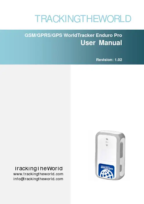
TRACKINGTHEWORLDTrackingTheWorld*************************General NotesTrackingTheWorld offers this information as a service to its customers, to support application and engineering efforts that use the products designed by TrackingTheWorld. The information provided is based upon requirements specifically provided to TrackingTheWorld by the customers. TrackingTheWorld has not undertaken any independent search for additional relevant information, including any information that may be in the customer’s possession. Furthermore, system validation of this product designed by TrackingTheWorld within a larger electronic system remains the responsibility of the customer or the customer’s system integrator. All specifications supplied herein are subject to change.CopyrightThis document contains proprietary technical information which is the property of TrackingTheWorld, copying of this document and giving it to others and the using or communication of the contents thereof, are forbidden without express authority. Offenders are liable to the payment of damages. All rights reserved in the event of grant of a patent or the registration of a utility model or design. All specification supplied herein are subject to change without notice at any time.Copyright © TrackingTheWorld 2010ContentsContents (2)0. Introduction (3)1. Product Overview (4)1.1. Appearance (4)1.2. Buttons/Mini USB Interface Description (4)1.3. LEDs Description (5)1.4. External Power Interface (5)1.4.1.External DC Charger Interface (5)1.4.2.External Battery Interface (6)1.5. External GPS antenna specification (7)1.6. Ignition Detection (7)2. Getting Started (8)2.1. Parts List (8)2.2. Battery Charging (9)2.3. WorldTracker Enduro Pro External Cable Interface (9)2.4. Install SIM Card (10)2.5. Install Device Into The Holder (10)2.6. Turn on/Turn off (10)3. Troubleshooting and Safety info (13)3.1. Troubleshooting (12)3.2. Safety info (13)0.IntroductionWorldTracker Enduro Pro is a powerful GPS locator designed for vehicle, pets and assets tracking. With superior receiving sensitivity, fast TTFF and GSM frequencies 850/900/1800/1900, its location can be real time or schedule tracked by backend server or specified terminals. Based on the embedded @Track protocol, WorldTracker Enduro Pro can communicate with the backend server through GPRS/GSM network, and transfer reports of emergency, Geo-fencing, device status and scheduled GPS position etc… It is easy for Service providers to setup their tracking platform based on the functional @Track protocol.1.Product Overview1.1. Appearance1.2.Buttons/Mini USB Interface Description1.3.LEDs DescriptionThere are three LED in WorldTracker Enduro Pro, the description as following.1.4. External Power Interface1.4.1.External DC Charger InterfaceThe Pin2 on Mini-USB connector are used for charging and named as VCHG pin. It can be connected to a 5V DC power supply to power WorldTracker Enduro Pro and charge the internal battery.1.4.2.External Battery InterfaceThe Pin 8 on Mini-USB connector is for external battery and named as EXTBAT pin. Itcan be connected to 3.7V Li-ion or Li-Polymer battery to power WorldTracker Enduro Pro.1.5. External GPS antenna specificationThere is a MMCX RF connector on WorldTracker Enduro Pro and it is for the external GPS antenna. The specification of the external GPS antenna is listed in the following table.1.6. Ignition DetectionThe Pin 7 on Mini-USB connector is for ignition detection when WorldTracker Enduro Pro is used in vehicle tracking application. It is named as IGN_IND pin.2.Getting Started 2.1.Parts ListWorldTracker Enduro Pro2.2.Battery Charging●Please connect AC-DC power adapter to WorldTracker Enduro Pro.●Insert the AC-DC power adapter into the power socket.●During charging, the PWR LED will flash fast. When the battery is fulyl charged, the PWR LEDwill be Ever-light.●You can also charge the battery by the USB cable, which connects the WorldTracker EnduroPro to a PC.●Charging time is about 5 hours.Note: Before the first time using WorldTracker Enduro Pro, please full charge the battery.2.3.WorldTracker Enduro Pro External Cable Interface●WorldTracker Enduro Pro External Cable is a cable with a Mini USB connector and four wires,which include the external power interface and ignition detect for WorldTracker Enduro Pro.Please find the detail description in following table.2.4.Install SIM Card●First, open the cover of SIM card.●Then insert the SIM card into the slot of SIM card according to the direction shown.●Finally, cover the slot.2.5.Install Device Into The Holder●Please install the WorldTracker Enduro into the Mini mage by:Remove the Door by unscrewing it and lifting it out.Slide the device into the case with the lights facing away from the magnetsReplace the door and screw into place.2.6.Turn on/Turn off●Turn on:◆Method 1: Press the Power key at least 3 seconds and release it to turn on WorldTrackerEnduro Pro. At the same time, PWR LED light will come on.◆Method 2: Connect device to charger or external battery, and it will turn on automatically,PWR LED light will turn on.●Turn off:◆Method 1: Press the power key about 2 seconds; PWR LED will flash fast and then turnoff. No lights lit indicates that the WorldTracker Enduro Pro is turned off. The time ofpower off is dependent on the quality of network. The maximum time of power off is 90seconds. It can only be turned off when using internal battery. Please note the end-usercannot power off the WorldTracker Enduro Pro when the power key is disabled byprotocol.◆Method 2: If using external battery, device will power off when the external battery isdisconnected.3. Troubleshooting and Safety info 3.1.Troubleshooting3.2.Safety info●Please do not disassemble the device by yourself.●Please do not storage the device in overly hot or humid places, avoid exposure to direct sunlight.Too high temperature will damage the device or even cause the battery to explode.●Please do not use WorldTracker Enduro Pro on an airplane or near medical equipment.。
T OMAHAWK ™625OPERATORʼS MANUALIM10020January, 2012Safety Depends on YouLincoln arc welding and cutting equipment is designed and built with safety in mind. However,your overall safety can be increased by proper installation ... and thoughtful operation on your part. DO NO T INSTALL,O PERATE O R REPAIR THIS EQUIPMENT WITHO UT READ-ING THIS MANUAL AND THE SAFETY PRECAUTIO NS CO N-TAINED THRO UGHO UT.And,most importantly, think beforeyou act and be careful.NOTESvfor selecting a QUALITY product by Lincoln Electric. We want you to take pride in operating this Lincoln Electric Company product ••• as much pride as we have in bringing this product to you!Read this Operators Manual completely before attempting to use this equipment. Save this manual and keep it handy for quick reference. Pay particular attention to the safety instructions we have provided for your protection.The level of seriousness to be applied to each is explained below:HIGH FREQUENCY INTERFERENCE PROTECTIONThe TOMAHAWK™ 625 employs a touch start mech-anism for arc initiation which eliminates high frequen-cy emissions from the machine as compared with spark gap and solid state type high frequency genera-tors. Keep in mind, though, that these machines may be used in an environment where other high frequen-cy generating machines are operating. By taking the following steps, high frequency interference into the TOMAHAWK™ 625 can be minimized(1)Make sure the power supply chassis is connectedto a good earth ground. The work terminal ground does NOT ground the machine frame.(2)Keep the work clamp isolated from other workclamps that have high frequency.(3)If the work clamp cannot be isolated, then keepthe clamp as far as possible from other work clamp connections.(4)When the machine is enclosed in a metal building,several good earth driven electrical grounds around the periphery of the building are recom-mended.Failure to observe these recommended installation procedures may cause improper function of the TOM-AHAWK™ 625 or possibly even damage to the control system or power supply components.INPUT ELECTRICAL CONNECTIONS The TOMAHAWK™ 625 is rated for 208VAC and 230VAC input voltage. Before installing the machine, check that input supply voltage, phase, and frequency are the same as the machine's voltage, phase, and frequency as specified on the machine's rating plate.• The TOMAHAWK™ 625 should be connected only by a qualified electrician. Installation should be made in accordance with local codes.For use on engine drives, keep in mind the above input draw restrictions and the following precaution. The TOMAHAWK™ 625 can be operated on engine driven generators as long as the 230 volt auxiliary meets the following conditions:• The AC waveform peak voltage is below 400 volts.• The AC waveform frequency is between 45 and 65 Hz.• The RMS voltage of the AC waveform is always greater than 208VAC.USER RESPONSIBILITYBecause design, fabrication, erection and cutting vari-ables affect the results obtained in applying this type of information, the serviceability of a product or struc-ture is the responsibility of the user. Variation such as plate chemistry, plate surface condition (oil, scale), plate thickness, preheat, quench, gas type, gas flow rate and equipment may produce results different than those expected. Some adjustments to procedures may be necessary to compensate for unique individ-ual conditions. Test all procedures duplicating actual field conditions.DESIGN FEATURES AND ADVANTAGESThe TOMAHAWK™ 625 design makes plasma cutting uncomplicated. This list of design features and advan-tages will help you understand the machine's total capabilities so that you can get maximum use from your machine.- Light weight and portable design for industrial use. - Continuous control, 10 - 40 amps.- Reliable touch start mechanism for plasma arc initi-ation.- Rapid arc restrike for fast cutting of expanded metal. - Input over voltage protection.- Bright 3.0 second timed pilot arc.- Purge section on output dial.- Air regulator and pressure gage included.- Internal water separator included.- Parts-in-Place mechanism to detect proper installa-tion of consumables and torch.- Preflow/Postflow timing. Preflow is eliminated if arc is re-initiated in Postflow.- Thermostatic Protection.- Solid state over-current protection.- Unique electrode and nozzle design for optimum cooling and long life.CUTTING CAPABILITYThe TOMAHAWK™ 625 is rated at 40 amps, at 35% duty cycle on a 10 minute basis. If the duty cycle is exceeded, a thermal protector will shut off the output of the machine until it cools to the normal operating temperature.Figure B.1 shows the cut capacity of the TOMA-HAWK™ 625 when cutting mild steel. (The graph plots cut thickness vs. torch travel speed with a torch standoff of 0.15".) CONSUMABLE LIFEThe expected life for the TOMAHAWK™ 625's elec-trode under normal operating conditions is approxi-mately 1000 starts/cuts. An erosion of .060" is typical for end of electrode life, however, the electrode life may last longer. A green and erratic arc will indicate definite electrode failure and the electrode should be replaced immediately.It is recommended that consumables be replaced in complete sets. (Example: Electrode and Nozzle). This will maximize the performance of the TOMAHAWK™625 system.Figure B.1 TOMAHAWK 625LIMITATIONSDo not exceed output current and duty cycle rating of machine. Do not use the TOMAHAWK™ 625 for pipe thawing.If the arc turns off while cutting using low input volt-age, that is below 208V, lower the air pressure by adjusting the regulator knob.When using with the Outback 180, gouging is not rec-ommended.Turn the machine's ON/OFF POWER SWITCH to the OFF position.• Connect the air supply to the machine.• Turn the main power on and the machine power switch to the ON position.- The fan will start.- The pre-charge circuit will operate for 3 seconds,then the green "Power" LED will illuminate.• Attach the work lead clamp to the workpiece before cutting.• Set the output current control knob to maximum position for higher cutting speed and less dross for-mation. Reduce the current, if desired to reduce the kerf (cut) width, heat affected zone, or travel speed as required.Note:If the circuit breaker trips while cutting at high-er amperages - reduce the cutting amperage on the unit, or provide an input circuit with higher current capacity.• Rotate the output knob into the purge zone to check or set the gas pressure. Pull the pressure regulator cap out and turn it to set the pressure.- Adjust the gas regulator for 75-80 PSI (0.50-0.55MPa).- Turn the output knob out of the purge zone.- The gas will immediately turn off. The pressure gage may show an increase in pressure after the air turns off but this is normal. Do NOT reset the pressure while the air is NOT flowing.PROCEDURE RECOMMENDATIONSWhen properly used, plasma arc cutting is a very eco-nomical process. Improper use will result in a very high operating cost.General - In All Cases• Follow safety precautions as printed throughout thisoperating manual and on the machine.• If piercing is required, slowly lower the torch at anangle of about 30° to blow the dross away from the torch tip and slowly rotate the torch to a ver-tical position as the arc becomes deeper. This process will blow a lot of molten metal and dross. Be careful! Blow the dross away from the torch, the operator and any flammable objects.• The nozzle should not be dragged on the metal surface. A drag spacer is provided to maintain a consistant touch height. Refer to Touch Parts Configurations in this Section.• Where possible, start the cut from the edge of thework piece.• Keep moving! A steady speed is necessary. Donot pause.• Replace the nozzle when the orifice exit is eroded away or oval shaped.• After the problem is found, or if there is nothing apparently wrong, reset the machine by turning the power switch OFF and then ON again. (It is possi-ble for electrical noise to trip the safety circuit on rare occasions. This should not be a regular occur-rence.)• If the machine does not reset or continues to trip,consult the Troubleshooting Section.• Use the proper cutting procedures referred to in Procedure Recommendations.PILOT ARC DISCUSSIONThe TOMAHAWK™ 625 has a smooth, continuous pilot arc. The pilot arc is only a means of transferring the arc to the workpiece for cutting. Repeated pilot arc starts, in rapid succession, is not recommended as these starts will generally reduce consumable life.Occasionally, the pilot arc may sputter or start inter-mittently. This is aggravated when the consumables are worn or the air pressure is too high. Always keep in mind that the pilot arc is designed to transfer the arc to the workpiece and not for numerous starts without cutting.The TOMAHAWK™ 625 does not utilize high frequen-cy starting. When the pilot arc is started, a slight impulse will be felt in the torch handle. This occur-rence is normal and is the mechanism which starts the plasma arc. This impulse can also be used to help troubleshoot a "no start" condition.Suggestions for Extra Utility from the TOMAHAWK™ 625 System:1. Occasionally an oxide layer may form over the tip of the electrode, creating an insulating barrier between the electrode and nozzle. This will result in the tripping of the TOMAHAWK™ 625's safety circuit. When this happens turn the power off,remove the nozzle and electrode and use the elec-trode to rub against the inside bottom surface of the nozzle. This will help remove any oxide buildup. Replace the nozzle, turn on the power and continue cutting. If the safety circuit continues to trip after cleaning the consumables, then replace them with a new set. Do not continue to try and cut with excessively worn consumables as this can cause damage to the torch head and will degrade cut quality. Do not allow torch cable or body to contact hot surface.2. To improve consumable life, here are some sug-gestions that may be useful:• Make sure the air supply to the TOMAHAWK™625 is clean and free of oil. Use several extra in line filters if necessary.• Minimize dross buildup on the nozzle tip by starting the cut from the edge of the plate when possible.• Pierce cutting should be done only when nec-essary. If piercing, angle torch about 30° from the plane perpendicular to the work piece,transfer the arc, then bring the torch perpendic-ular to the work and begin parallel movement.• Reduce the number of pilot arc starts without transferring to the work.• Reduce the pilot arc time before transferring to the work.• Set air pressure to recommended setting. A higher or lower pressure will cause turbulence in the plasma arc, eroding the orifice of the nozzle tip.• Use only Lincoln consumable parts. These parts are patented and using any other replace-ment consumables may cause damage to the torch or reduce cut quality.TORCH PART CONFIGURATIONSThere are different torch configurations depending onthe cutting or gouging application.Standard Cutting Setup:In the Standard Cutting configuration the nozzle isdesigned not to touch the work piece. The advantageof this cutting method is good visibility of the arc.However it requires a steady hand to avoid touchingthe nozzle to the work piece which will cause prema-ture nozzle wear and a jagged cut. An optional dragspacer can be attached to the retaining cap to main-tain a consistent arc height.Contact Cutting Setup:Contact Cutting uses special expendable parts thatallow the torch to touch the work piece. The advan-tage of contact cutting is that the torch can touch thework piece, steadily dragging it across the surface.The disadvantage of contact cutting is the plasma arcis not as visible as with a standard torch set-up. Sincethis machine cuts at 40 amps or less it uses the directcontact torch configuration which allows a special noz-zle to come in contact with the work piece.Gouging Setup:If gouging metal and not cutting completely through the part is required, a special gouging nozzle is used in conjunction with a gouge shield to protect the noz-zle from molten metal blow back.Refer to the torch parts decal located on your machine or the parts pages at the back of this manual for the specific part numbers required for each of these setups.ALWAYS USE GENUINE LINCO LN ELECTRIC ELECTRO DES, NO ZZLES, AND EXPENDABLE PARTS FO R THE BEST CUTTING PERFO R-MANCE.GENERAL OPTIONS /ACCESSORIESThe following options/accessories are available for your Tomahawk Plasma cutter from your local Lincoln Distributor.K2377-1-Small Canvas CoverProtect your machine when not in use. Made from attractive red canvas that is flame retardant, mildew resistant and water repellent. It includes a convenient side pocket to hold the plasma torch.K2886-1- Plasma Circle Cutting KitFor cutting circles from 3” to 33” in diameter (77mm to 838mm).TORCHESThe following replacement torch is available:K2847-1 LC40 Handheld Plasma Torch 20' (6m) EXPENDABLE PARTSRefer to the torch parts decal located on your machine or the parts pages at the back of this manual for the specific part numbers required for each of the avail-able setups.This Troubleshooting Guide is provided to help you locate and repair possible machine malfunctions. Simply follow the three-step procedure listed below.Step 1.LOCATE PROBLEM (SYMPTOM).Look under the column labeled “PROBLEM (SYMPTOMS)”. This column describes possible symptoms that the machine may exhibit. Find the listing that best describes the symptom that the machine is exhibiting. Step 2.POSSIBLE CAUSE.The second column labeled “POSSIBLE CAUSE” lists the obvious external possibili-ties that may contribute to the machine symptom.Step 3.RECOMMENDED COURSE OF ACTIONThis column provides a course of action for the Possible Cause, generally it states to contact you local Lincoln Authorized Field Service Facility.If you do not understand or are unable to perform the Recommended Course of Action safely, contact you local Lincoln Authorized Field Service Facility.STATUS BOARD INDICATORSJapaneseChineseKoreanArabicREAD AND UNDERSTAND THE MANUFACTURER’S INSTRUCTION FOR THIS EQUIPMENT AND THE CONSUMABLES TO BE USED AND FOLLOW YOUR EMPLOYER’S SAFETY PRACTICES.SE RECOMIENDA LEER Y ENTENDER LAS INSTRUCCIONES DEL FABRICANTE PARA EL USO DE ESTE EQUIPO Y LOS CONSUMIBLES QUE VA A UTILIZAR, SIGA LAS MEDIDAS DE SEGURIDAD DE SU SUPERVISOR.LISEZ ET COMPRENEZ LES INSTRUCTIONS DU FABRICANT EN CE QUI REGARDE CET EQUIPMENT ET LES PRODUITS A ETRE EMPLOYES ET SUIVEZ LES PROCEDURES DE SECURITE DE VOTRE EMPLOYEUR.LESEN SIE UND BEFOLGEN SIE DIE BETRIEBSANLEITUNG DER ANLAGE UND DEN ELEKTRO-DENEINSATZ DES HERSTELLERS. DIE UNFALLVERHÜTUNGSVORSCHRIFTEN DES ARBEITGEBERS SIND EBENFALLS ZU BEACHTEN.JapaneseChineseKoreanArabicLEIA E COMPREENDA AS INSTRUÇÕES DO FABRICANTE PARA ESTE EQUIPAMENTO E AS PARTES DE USO, E SIGA AS PRÁTICAS DE SEGURANÇA DO EMPREGADOR.• Sales and Service through Subsidiaries and Distributors Worldwide •Cleveland, Ohio 44117-1199 U.S.A. TEL: 216.481.8100 FAX: 216.486.1751 WEB SITE: 。
Enduro PlusMulti-purpose Tracking DeviceUSER MANUALa c k i n g T h e W o r l d.c o mGeneral NotesTrackingTheWorld offers this information as a service to its customers, to support application and engineering efforts that use the products designed by TrackingTheWorld. The information provided is based upon requirements specifically provided to TrackingTheWorld by the customers. TrackingTheWorld has not undertaken any independent search for additional relevant information, including any information that may be in the customer’s possession. Furthermore, system validation of this product designed by TrackingTheWorld within a larger electronic system remains the responsibility of the customer or the customer’s system integrator. All specifications supplied herein are subject to change.CopyrightThis document contains proprietary technical information which is the property of TrackingTheWorld, copying of this document and giving it to others and the using or communication of the contents thereof, are forbidden without express authority. Offenders are liable to the payment of damages. All rights reserved in the event of grant of a patent or the registration of a utility model or design. All specification supplied herein are subject to change without notice at any time.Copyright © TrackingTheWorld 2016For More Information: Please contact TrackingTheWorld, 1633 Bayshore Highway, Suite 390, Burlingame, CA. 94010, USA Phone: +1.650.692.8100 – Email: *************************– Website: ContentsContents (3)0. Revision history (4)1. Introduction (5)2. Product Overview (6)2.1. Appearance (6)2.2. Buttons/Mini USB Interface Description (6)2.3. LEDs Description (7)2.4. External Power Interface (7)2.4.1. External DC Charger Interface (7)2.4.2. External Battery Interface (8)2.5. Ignition Detection (8)2.6. External Input Interface (9)3. Getting Started (10)3.1. Parts List (10)3.2. Battery Charging (11)3.3. ENDURO PLUS External Cable Interface (11)3.4. Install SIM Card (12)3.5. Turn on/Turn off (12)4. Troubleshooting and Safety info (13)4.1. Troubleshooting (13)4.2. Safety info (14)For More Information: Please contact TrackingTheWorld, 1633 Bayshore Highway, Suite 390, Burlingame, CA. 94010, USA Phone: +1.650.692.8100 – Email: *************************– Website: 0.Revision historyFor More Information: Please contact TrackingTheWorld, 1633 Bayshore Highway, Suite 390, Burlingame, CA. 94010, USA Phone: +1.650.692.8100 – Email: *************************– Website: 1.IntroductionENDURO PLUS is a powerful GPS Tracker designed for asset, vehicle, and pet tracking. With superior receive sensitivity, fast TTFF (Time to First Fix) and Quad band GSM frequencies 850/900/1800/1900, its location can be continuously monitored or periodically reported to a backend server or other device. Based on the embedded @Track protocol, the ENDURO PLUS can communicate with the backend server through the GPRS/GSM network (or SMS) to report emergency alerts, Geo-Fence boundary crossings, low battery and scheduled GPS positions along with several other advanced reporting features. System integrators can easily setup their custom tracking platforms to communicate with the ENDURO PLUS based on the @Track protocol.This device complies with Part 15 of the FCC Rules. Its operation is subject to the following two conditions:(1) This device may not cause harmful interference, and(2) This device must accept any interference received, including interference that may cause undesired operation.Note: This product has been tested and found to comply with the limits for a Class B digital device, pursuant to Part 15 of the FCC Rules. These limits are designed to provide reasonable protection against harmful interference in a residential installation. This product generates, uses, and can radiate radio frequency energy and, if not installed and used in accordance with the instructions, may cause harmful interference to radio communications. However, there is no guarantee that interference will not occur in a particular installation. If this product does cause harmful interference to radio or television reception, which can be determined by turning the equipment off and on, the user is encouraged to try to correct the interference by one or more of the following measures:—Reorient or relocate the receiving antenna.—Increase the separation between the equipment and receiver.—Connect the equipment into an outlet on a circuit different from that to which the receiver is connected.—Consult the dealer or an experienced radio/TV technician for help.For More Information: Please contact TrackingTheWorld, 1633 Bayshore Highway, Suite 390, Burlingame, CA. 94010, USA Phone: +1.650.692.8100 – Email: *************************– Website: Copyright © TrackingTheWorld. All rights reserved. Information in this publication supersedes that in all previously published material. Specification and priceFor More Information: Please contact TrackingTheWorld, 1633 Bayshore Highway, Suite 390, Burlingame, CA. 94010, USAPhone: +1.650.692.8100 – Email: ************************* – Website: Copyright © TrackingTheWorld. All rights reserved. Information in this publication supersedes that in all previously published material. Specification and price 2. Product Overview2.1. Appearance2.2. Buttons/Mini USB Interface DescriptionGPS LEDFunction KeyMiniUSB InterfaceSIM Card SlotPower KeyPWR LEDGSM LED2.3.LEDs DescriptionThere are three LEDs in ENDURO PLUS, the description as following.2.4.External Power Interface2.4.1.External DC Charger InterfaceThe Pin2 on Mini-USB connector are used for charging and named as VCHG pin, It can be connected to a 5V DC power supply to power ENDURO PLUS and charge the internal battery.For More Information: Please contact TrackingTheWorld, 1633 Bayshore Highway, Suite 390, Burlingame, CA. 94010, USA Phone: +1.650.692.8100 – Email: *************************– Website: Copyright © TrackingTheWorld. All rights reserved. Information in this publication supersedes that in all previously published material. Specification and price2.4.2.External Battery InterfaceThe Pin 8 on Mini-USB connector is for external battery and named as EXTBAT pin. It can be connected to 3.7V Li-ion or Li-Polymer battery to power ENDURO PLUS.2.5. Ignition DetectionThe Pin 7 on Mini-USB connector is for ignition detection when ENDURO PLUS is used in vehicle tracking application. It is named as IGN_IND pin.For More Information: Please contact TrackingTheWorld, 1633 Bayshore Highway, Suite 390, Burlingame, CA. 94010, USA Phone: +1.650.692.8100 – Email: *************************– Website: Copyright © TrackingTheWorld. All rights reserved. Information in this publication supersedes that in all previously published material. Specification and priceAnother easy way is to connect PIN7 to a power output in the fuse box of the vehicle which is only enabled after the vehicle is ignition on. For example: the power output for radio FM.2.6. External Input InterfaceThe Pin 5 on Mini-USB connector is a negative trigger input in newer hardware version. It is named as NSW pin.For negative trigger input the electrical conditions are:An input example is shown as following figures:For More Information: Please contact TrackingTheWorld, 1633 Bayshore Highway, Suite 390, Burlingame, CA. 94010, USA Phone: +1.650.692.8100 – Email: *************************– Website: Copyright © TrackingTheWorld. All rights reserved. Information in this publication supersedes that in all previously published material. Specification and priceExample of NSW pin connect to a panic button3.Getting Started3.1.Parts ListThe GSM/GPRS/GPS locator.It is used to charge the internalbattery of ENDURO PLUS.For More Information: Please contact TrackingTheWorld, 1633 Bayshore Highway, Suite 390, Burlingame, CA. 94010, USA Phone: +1.650.692.8100 – Email: *************************– Website: Copyright © TrackingTheWorld. All rights reserved. Information in this publication supersedes that in all previously published material. Specification and priceIt is the USB data cable which canbe used for firmware upgrading andconfiguration.It is the extend cable which includethe charger interface and externalbattery interface on ENDURO PLUS.It also includes the ignitiondetection interface on the ENDUROPLUS.3.2.Battery Charging●Please connect AC-DC power adapter with ENDURO PLUS.●Insert the AC-DC power adapter into the power socket.●During charging, the PWR LED is flashing fast. When the battery is full charged, the PWR LED will be Ever-light.●You can also charge the battery by USB cable which connects ENDURO PLUS with the PC.●Charging time is about 5 hours.Note: Before the first time using ENDURO PLUS, please full charge the battery.3.3.ENDURO PLUS External Cable Interface●ENDURO PLUS External Cable is a cable with a Mini USB connector and six wires which include the externalpower interface, ignition detect and input interface for ENDURO PLUS. Please find the detail description in following table.For More Information: Please contact TrackingTheWorld, 1633 Bayshore Highway, Suite 390, Burlingame, CA. 94010, USA Phone: +1.650.692.8100 – Email: *************************– Website: Copyright © TrackingTheWorld. All rights reserved. Information in this publication supersedes that in all previously published material. Specification and price3.4.Install SIM Card●First, open the cover of SIM card..●Then insert the SIM card into the slot of SIM card according to the direction shown.●Finally, cover the slot.3.5.Turn on/Turn off●Turn on:◆Method 1: Press the Power key at least 3 seconds and release it to turn on ENDURO PLUS. At thesame time, PWR LED will light on.◆Method 2: Connect device to charger or external battery, and it will turn on automatically, PWR LEDwill light on.●Turn off:◆Method 1: Press the power key about 2 seconds; PWR LED will fast flash and then turn off, it indicatesthat ENDURO PLUS is turned off. The time of power off is depended on the quality of network. The maximum time of power off is 90 seconds. It is only valid to turn off when using internal battery.Please note the end-user cannot power off ENDURO PLUS when the power key is disabled by protocol.◆Method 2: If using external battery, device will power turn-off when external battery disconnect. For More Information: Please contact TrackingTheWorld, 1633 Bayshore Highway, Suite 390, Burlingame, CA. 94010, USA Phone: +1.650.692.8100 – Email: *************************– Website: Copyright © TrackingTheWorld. All rights reserved. Information in this publication supersedes that in all previously published material. Specification and price4. Troubleshooting and Safety info4.1.TroubleshootingFor More Information: Please contact TrackingTheWorld, 1633 Bayshore Highway, Suite 390, Burlingame, CA. 94010, USA Phone: +1.650.692.8100 – Email: *************************– Website: Copyright © TrackingTheWorld. All rights reserved. Information in this publication supersedes that in all previously published material. Specification and price4.2.Safety info●Please do not disassemble the device by yourself.●Please do not put the device on the overheating or too humid place, avoid exposure to direct sunlight. Toohigh temperature will damage the device or even cause the battery explosion.●Please do not use ENDURO PLUS on the airplane or near medical equipment.For More Information: Please contact TrackingTheWorld, 1633 Bayshore Highway, Suite 390, Burlingame, CA. 94010, USA Phone: +1.650.692.8100 – Email: *************************– Website: Copyright © TrackingTheWorld. All rights reserved. Information in this publication supersedes that in all previously published material. Specification and price。
智能健身跟踪器使用说明书尊敬的用户:感谢您购买智能健身跟踪器。
本使用说明书将为您提供详细的操作指南,让您轻松了解和使用本产品。
1. 产品概述智能健身跟踪器是一款功能强大的运动记录装备,可以监测您的运动数据,包括步数、卡路里消耗、心率等,通过与智能手机连接,还可以实时同步您的运动记录、睡眠情况等信息。
2. 功能特点2.1 运动跟踪:智能健身跟踪器准确记录您的步数、运动里程以及消耗的卡路里,帮助您全面了解自己的运动情况。
2.2 心率监测:装备有高精度的心率传感器,能够实时监测并记录您的心率数据,助您更有效地管理运动强度。
2.3 睡眠监测:通过智能健身跟踪器的睡眠检测功能,您可以了解自己的睡眠质量,追踪深度睡眠和浅度睡眠时间以及醒来次数。
2.4 来电提醒:当您的手机接听来电时,智能健身跟踪器会振动提醒,方便您不错过重要电话。
2.5 智能提醒:智能健身跟踪器通过与智能手机连接,还可以实时提醒您的短信、社交媒体消息等。
3. 使用步骤3.1 充电:使用随附的充电器连接智能健身跟踪器的充电端口,将其插入电源插座进行充电。
充电指示灯将亮起,当指示灯熄灭时,表示充电完成。
3.2 下载APP:打开智能手机上的应用商店,搜索并下载配套的APP,然后按照APP的提示进行安装。
3.3 配对连接:将智能健身跟踪器与智能手机进行配对连接,打开手机上的蓝牙功能,并在APP中搜索智能健身跟踪器,选择连接。
3.4 个人设置:在APP中设置个人信息,包括身高、体重等基本信息,以确保智能健身跟踪器能准确记录运动情况。
3.5 开始运动:佩戴智能健身跟踪器,点击开始按钮,即可开始记录运动数据。
您可以自由选择运动模式,如跑步、骑行、健身等。
3.6 数据同步:在运动结束后,打开APP,智能健身跟踪器将自动同步记录的数据至手机。
您可以在APP中查看完整的运动报告和趋势图表。
4. 注意事项4.1 请确保智能健身跟踪器充电充足,以免影响其正常使用。
MODEL 06206MARINE WIND TRACKERNOVEMBER 2001MANUAL PN 06206-90R. M. YOUNG COMPANY西安威瑞贸易有限公司主营全球知名:无损检测设备气象科学仪器设备TEL:029-********FAX*************-8848EMAIL:*****************INTRODUCTIONThe YOUNG Model 06206 Marine Wind Tracker is a compact wind speed and wind direction display. This model has features such as relative wind angle and NMEA compatibility that make it suitable for shipboard use.FEATURES• 3 digit wind speed display• 3 digit maximum wind speed or wind direction display•Multi-color wind direction display with variability display•Wind speed and direction alarms with delay•RS-485/NMEA serial connections•Calibrated 0-5 VDC outputs•Display brightness control•4-20 mA Sensor Inputs•Luminous front panel markingsPRECAUTIONS•INDOOR USE ONLY unless placed in approved enclosure.•Operating temperature range 0-50°C (32-122°F), 0-95% RH.•Use only recommended power sources; 12-30VDC, 4.5 W.•Disconnect power when making connections or servicing sensors.•MAXIMUM 24 VAC/30 VDC on alarm relay contacts.FRONT PANEL1.Wind Speed Display2.Wind Speed Units Indicator3.Alarm Status Indicators4.Maximum Wind Speed or Relative Wind Direction Display5.Relative Wind Direction and Variability Display6.Brightness (operate mode), ENTER (setup mode)7.MAX RESET (operate mode), SELECT (setup mode) BACK PANEL1.Power input (12-30 VDC) AC adapter supplied2.Sensor or 4-20 mA inputs3.Earth ground connection4.RS-485/NMEA serial connections5.0-5 VDC calibrated outputs6.Alarm relay connections (normally open)7.Input selector switchMOUNTING AND START-UP1.Select location for display. A location out of direct sunlight providesbest visibility.The Wind Tracker may be mounted from a bulkhead or installed ina flush panel by removing the mounting bracket. Panel cutoutdimensions are given in the specifications. An optional rack mounting panel (Model 06280) and protective enclosure (Model 06260) are available from your YOUNG supplier.2.Connect cables to terminals. Refer to diagrams on page 5.Selector switch (item 7 on back panel illustration) should be DOWN for normal sensor inputs, UP for 4-20 mA or Wind Monitor-SE signals.3.Connect GND terminal to suitable earth ground.4.Insert power supply plug into power jack, plug into standard ACwall outlet.The Wind Tracker may also be powered from ships batteries. A coaxial power plug (2.1mm) must be used. Center is positive.5.The Wind Tracker will display a software version number forapproximately 4 seconds. It then begins to display wind informa-tion. The following information is displayed:•Wind Speed•Wind Speed Units•Maximum Wind Speed or Direction degrees•Relative Wind Direction (single orange indicator)•Direction Variability (green indicators)•WS, WD Alarm Status Indicators (if selected)6.Observe the unit for a few minutes to verify that it is operatingproperly. If you wish to change settings (ie: wind speed units). See the following section.CHANGING SETTINGSThe Wind Tracker has a setup mode that allows you to easily change sensor type, wind speed units, alarm settings, and other functions.Press and hold ENTER and SELECT keys (about 5 seconds). The display will briefly flash “SET UP”, then begin the SETUP sequence. Change settings with the SELECT key. Press the ENTER key to save a setting and move to the next step. Abbreviations in the left and right display windows identify each function and the available selections.DISPLAY SETUP FUNCTIONLEFT RIGHTInput/Sensor TypeInP LDi Line Driver 4-20 mA input03Wind Sentry04Wind Monitor-Jr05Wind Monitor, Wind Monitor-MASEr Serial input from Wind Monitor-SE or main displayIf SEr is selected, wind speed units and NMEAoutput rate selections do not appear.Wind Speed UnitsSPd unt Press SELECT to change units, ENTER toproceed.NMEA Output RateOUT FST16 sentences sent per secondSLO 1 sentence sent per secondDisplaydSP SPd Displays MAXIMUM wind speed in right display.dir Displays WIND DIRECTION degrees(1° resolution) in right display.Wind Direction AlarmALr no WD alarm not used.YES WD alarm activated.If no is selected, the following 2 steps do notappear.ALr dir Press SELECT to position alarm sector.Press ENTER.ALr SPn Press SELECT to set size (span) of alarmsector.Wind Speed AlarmALr no WS alarm not used.YES WS alarm activated.If no is selected, the following step does notappear.ALr000WS alarm set point. Press SELECT tochange digits. ENTER to save.If no alarm is selected, the following 2 steps do notappear.Alarm Delay TimedLY030Set alarm delay time in seconds (0-999).SoundSnd no No sound with alarm.YES Audible beeper will sound with alarm.Test FunctionstSt no Skip test functions.YES For troubleshooting only. YES will initiate thefollowing tests.If no is selected, the unit will return to normaloperation.tSt Snd Press SELECT to sound beeper.tSt dSP Press SELECT to illuminate all display seg-ments.tSt ALr Press SELECT to close alarm relays.CAL0.00Press SELECT to alternate between 0.00 Vout and5.00 Vout at terminals. Use to calibrate externaldevices (recorders, etc..)ADDITIONAL INFORMATIONALARMSWind speed and wind direction alarm functions are accessed in the SETUP sequence. Either or both alarms may be used. When activated, alarms are indicated on the front panel. When an alarm condition exists, the indicator will blink and the associated relay contact will close and the beeper will sound if selected in SETUP. When a delay time is set, the indicator will not report an alarm condition until it has existed for one complete delay period. Alarm activity will cease when conditions are outside the alarm range for one complete delay period. For a "latching" alarm effect, use the Wind Tracker alarm contacts to activate an external latching-type relay.BRIGHTNESSAdjust display brightness by holding the BRIGHT key.MAXIMUM / WIND DIRECTION DIGITAL DISPLAYThe right display window can show either MAXIMUM WIND SPEED or Numerical WIND DIRECTION. This selection is made in the setup mode under Display (dSP).NMEA OUTPUTThe Wind Tracker features NMEA serial output from the RS-485 terminals. These terminals can be used to operate remote displays or connect to other NMEA compatible devices. The NMEA output sen-tence is sent 16 times per second (Fast) or once per second (Slow) depending on the NMEA Output (OUT) setting in SETUP. For best remote display, use the Fast setting.REMOTE DISPLAYSThe Wind Tracker can be used as a remote display by selecting "InP SEr" during SETUP. Remote displays are connected to the main display using the RS-485 terminals. NMEA Serial Protocol is used to operate remote displays. Up to 16 remote displays can be connected to one main display. Use the serial input when connecting to a Model 09101 Wind Monitor-SE sensor. See wiring diagram.VOLTAGE OUTPUTSThe Wind Tracker offers calibrated voltage outputs for both wind speed and wind direction. This feature allows the use of recorders and other devices. Full scale voltage for each channel is 5.00 VDC.4-20mA INPUTSThe Wind Tracker accepts 4-20 mA (Line Driver) inputs. Line Driver circuit must provide 0-50 M/S Wind Speed scaling ("M" suffix). Connect cable as indicated on page 4. Slide switch on back must be UP at power up for correct 4-20 mA operation. Select LDI as input in SETUP.24 VDC power is required for line driver applications.ERROR MESSAGESThe Wind Tracker detects and indicates two errors. Once corrected, the error indication disappears.DISPLAYLDi Err4-20 mA (line driver) signal. Signal is missing oroutside of acceptable range. Verify properswitch position or signal.SEr Err Unit is set to receive RS-485 NMEA serialsignal, but no serial data is coming in. Verify thatNMEA source is operating. Check cables forproper connection.WARRANTYThe Wind Tracker is warranted to be free of defects in materials and construction for a period of 12 months from date of purchase. Coverage is limited to repair or replacement of defective unit. SPECIFICATIONSSize:144 mm (5.65 in) x 144 mm (5.65 in) x 36 mm (1.4 in)Panel Cutout: 138 mm (5.43 in) x 138 mm (5.43 in)Compatible Sensors:Wind Monitor-SEWind MonitorWind Monitor-MAWind Monitor-JRWind SentryOther Inputs:4-20 mANMEA Serial Input/Output$WIMWV,ddd,R,sss,u,A[CR][LF]where:ddd wind direction in degreessss wind speed (ss.s for m/s)u units (N = knots, K = kilometers/hour,M = meters/second, S = miles/hour) Accuracy:±0.6% F.S.Display Resolution:Wind Direction:10° circular pattern (36 points)1° w/ dSP dIr selectedWind Speed &Maximum: 1 Knot, 1 MPH, 1 KM/H, 0.1 M/S Voltage Outputs:Wind Direction Range:0-5 VDC 0-360°Wind Speed Range: (dependent on units selected)0-5 VDC0-100 Knots0-100 MPH0-200 KM/H0-50 M/SAlarm Relays:Non-latchingNormally Open contacts for WS and WD.Contact rating 5A resistive,2A inductive @ 24 VAC, 30 VDC.Input Power:12-30 VDC, 4.5 WWeight: 1.0 lb (.45 kg) without AC adapterCE COMPLIANCEThis product has been tested and shown to comply with European CErequirements for the EMC Directive. Please note that shielded cablemust be used.Declaration of ConformityApplication of Council Directives:89/336/EECStandards to which Conformity is Declared:EN 50081-1EN 55022 (CISPR 22 class A)EN 50082-1 (IEC 801-2, 3, 4)Manufacturer's Name and Address:R. M. Young CompanyTraverse City, MI, 49686, USAImporter's Name and Address:See Shipper or InvoiceType of Equipment:Meteorological InstrumentsModel Number/Year of Manufacture:06206/1996I, the undersigned, hereby declare that the equipmentspecified conforms to the above Directives and Standards.Date / Place:Traverse City, Michigan, USA February 19, 1996David PoinsettR & D Manager, R. M. Young Company西安威瑞贸易有限公司主营全球知名丗无损检测设备气象科学仪器设备TEL:029-********FAX*************-8848EMAIL:*****************。
Trail CameraV1.4USER MANUALBEFORE USE.Precautions• Do not clean the camera with chemicals or solvents such as cleaning solutions or detergents.• Do not expose the camera to magnetic fields, such as electrical motors or magnets.• Do not expose the camera to high or low temperatures. The normal operating temperature of the camera is 0ºC to 60ºC(32F to 104F). High temperatures can shorten the lifespan of electronic devices and extremely high/low temperatures willshorten the battery life and/or degrade the plastic components.• Before you start recording with the camera, format the memory card in the settings menu or on a computer to avoidpotential camera or card malfunctions. Memory cards should be formatted regularly to avoid potential camera or cardmalfunctions.• If dust or dirt is on the camera or on its lens, use a soft, clean and dry cloth to wipe away debris gently.• Take care and prevent water or sand particles from entering the housing. Water, sand particles and dust containing saltmay cause damage.• Do not use a cloth to wipe sand particles. Gently blow them away then wipe the camera with a soft cloth.• Weather resistant case is not submersibleOverviewFront BaseBackInstalling and Removing The Micro SD Card1. Make sure the camera is off when inserting or removing the micro SD card.2. Insert the memory card in the correct direction.Damaged or lost data may occur if installed incorrectly.3. To remove the micro SD card, using your fingernail, press down on the card until itclicks. It will now pop up out of the camera.Turning The Camera ON / SET / OFFCAMERA STANDBY MODESlide the power switch to the ‘ON’ position. Camera will then enter the stand-by mode and will automatically take videos/pictures based on theinterval setting and video length setting.TURNING OFF THE CAMERASlide the power switch to the ‘OFF’ position.SET MODESlide the power switch to the ‘SET’ position. You can now take pictures & videos or re play photos and videos. As well as changing the camera's settings.Capture ModesVIDEO | PHOTOTo switch between modes, press the up or down button whilst in ‘SET’ mode.Once desired capture mode is selected, slide the power button to ‘ON’. A 15s timer will start to indicate when the camera will start recording.VIDEO CAPTURE MODE:Press UP on the keypad to use this mode to capture video. Under the SET mode, press the RIGHT button to start recording, press the RIGHT button a gain to end recording.PHOTO CAPTURE MODE:Press DOWN on the keypad to use this mode to take photos. Press theRIGHT button to take a photo.REPLAY MODE:Use this mode to view and manage photos and videos.Press the OK button to view the recorded video, use the Up and Downbuttons to scroll through the recorded video/photo files. Press the RIGHTbutton on the keypad to play, press the MENU for set-up options.Camera Settings• Press the Menu button once to access the settings menu.• Once in the settings menu, use the Up and Down buttons to scroll through the various options.• Press the OK button to confirm any settings options selected.Press the Menu button to exit.•Specifications:Transferring Files to A Computer1. Turn the camera ON and connect to a PC or MAC’s USB2.0 port via the supplied micro USB cable. The camera screen will display a connecting screen.2. Your captured videos and images will be accessible from your computer. Note: Alternatively, you can remove the Micro SD Card from the camera and insert the card into a card reader.Screen 2.36 Inch TFT LCD Sensor3 Mega Pixel Colour CMOS PIR Sensing Angle 60°PIR Sensing Distance 20M Photo Format .JPG Video Format .MOV Video Code H.264Video Resolution1920x1080 1280x720720x480640x480Photo Resolution 16M / 12M / 8M / 5M / 3M / 1M Micro SD Card Supports SD (Class 10)USB Port Mini 5 Pin USB 2.0DC Power 6V / 1.5A Battery4 ~ 8 AA BatteriesWARRANTY PERIOD:Full 12 month warranty from date of purchase against all manufacturing defects.WHAT DOES THE WARRANTY COVER?Under normal usage conditions, this warranty covers:a. Any defect in design or manufacture which results in the product failing to perform substantially as described in authorised advertising or literature.b. We will either repair or replace the product at our discretion providing that the fault is found to have been caused by a design or manufacturing defect and not misuse or tampering.Our goods come with guarantees that cannot be excluded under the Australian Consumer Law. You are entitled to a replacement or refund for a major failure and for compensation for any other reasonablyforeseeable loss or damage. You are also entitled to have the goods repaired or replaced if the goods fail to be of acceptable quality and the failure does not amount to a major failure. The bene ts provided to you as the consumer by this warranty are in addition to other rights and remedies available to you under the law.THE WARRANTY DOES NOT COVER:a. Any damage resulting from improper useb.c. The cost of removing and reinstalling the productd. Travel and /or other expenses due to customer’s remote locatione. Transport charges and damage in transit. It is your responsibility to deliver and pick up your product,including any costs associated with the postage of your repair or replacement product. If you do freight your product we recommend that you insure against loss or damage.f. Any loss directly or indirectly associated with the product failing to operate.g. Damage caused by mould, insects, animals, misuse, incorrect operation, adverse weather, accidents and fair wear and tearTO MAKE A CLAIM, PLEASE ENSURE YOU RETAIN YOUR SALES RECEIPT OF PURCHASE1800 88 39 6412 MONTH LIMITEDWARRANTYOUTDOOR SUPACENTRE PTY LTD 2 Stanley St Silverwater NSW, 2128PHONE: 1800 88 39 64.au。
G P S T R A C K E R追踪王(GPS+AGPS+LBS+GSM+SMS/GPRS)使用指南(版本V1.0)非常感谢你选择使用GPS TRACKER追踪王,使用指南将详细的说明如何操作本产品。
请你在使用之前认真阅读使用指南,以便得到正确使用方法。
如有更改,恕不另行通知,每次更改将统一在最新的一次产品销售中发布,制造商对于使用指南中的过失和疏漏不承担法律责任。
目录1.产品简介2.应用领域3.规格描述4.产品配件5.使用说明5.1 SIM卡的安装和设备启动5.2设备充电5.3主控号码设置5.4单次定位5.5基站定位5.6中文地址查询5.7 SOS紧急求救5.8远程监听5.9震动报警5.10位移报警5.11电子围栏5.12超速报警5.13低电报警5.14睡眠省电模式设置5.15设防/重启和恢复出厂设置5.16 查询设备状态6.监控平台应用7.故障排除8.保修1.产品简介GPS TRACKER追踪王融合了GSM无线通信技术及GPS全球定位系统技术,采用工业级防火材料,6颗18MM×3MM强磁装置,IPX-5防水等级设计,内置8000MAH大容量电池,超长待机100天,通过短信和全球定位服务平台实现对远程目标进行定位和监控管理。
强磁免安装设计,简单易用。
2.应用领域●汽车租赁/小型车队管理●户外活动●儿童/老人/残疾人士/贵重物品的监护●个人安全●人员管理●跟踪定位●动物保护和放牧3.规格描述4.产品配件●5V 1000MA充电器一个●充电线一条●使用指南和保修卡一本●GPS TRACKER追踪王设备一台5.使用说明5.1 SIM卡的安装和设备启动5.1.1 打开包装盒,检查设备型号是否正确,配件是否齐全,否则请联络你的经销商;5.1.2 SIM卡选择,设备需要插入一张GSM SIM卡,GSM卡联通或移动任选(GSM网络全球通用)5.1.3 SIM卡的安装,拆开设备防水塞,依据标示,SIM卡芯片朝下插入卡槽,盖上防水塞。
G P S T R A C K E R追踪王
(GPS+AGPS+LBS+GSM+SMS/GPRS)
使用指南
(版本)
非常感谢你选择使用GPS TRACKER追踪王,使用指南将详细的说明如何操作本产品。
请你在使用之前认真阅读使用指南,以便得到正确使用方法。
如有更改,恕不另行通知,每次更改将统一在最新的一次产品销售中发布,制造商对于使用指南中的过失和疏漏不承担法律责任。
目录
1.产品简介
2.应用领域
3.规格描述
4.产品配件
5.使用说明
SIM卡的安装和设备启动
设备充电
主控号码设置
单次定位
基站定位
中文地址查询
SOS紧急求救
远程监听
震动报警
位移报警
电子围栏
超速报警
低电报警
睡眠省电模式设置
设防/重启和恢复出厂设置
查询设备状态
6.监控平台应用
7.故障排除
8.保修
1.产品简介
GPS TRACKER追踪王融合了GSM无线通信技术及GPS全球定位系统技术,采用工业级防火材料,6颗18MM×3MM强磁装置,IPX-5防水等级设计,内置8000MAH大容量电池,超长待机100天,通过短信和全球定位服务平台实现对远程目标进行定位和监控管理。
强磁免安装设计,简单易用。
2.应用领域
●汽车租赁/小型车队管理
●户外活动
●儿童/老人/残疾人士/贵重物品的监护
●个人安全
●人员管理
●跟踪定位
●动物保护和放牧
● 5V 1000MA充电器一个
●充电线一条
●使用指南和保修卡一本
●GPS TRACKER追踪王设备一台
5.使用说明
SIM卡的安装和设备启动
打开包装盒,检查设备型号是否正确,配件是否齐全,否则请联络你的经销商;
SIM卡选择,设备需要插入一张GSM SIM卡,GSM卡联通或移动任选(GSM网络全球通用)
SIM卡的安装,拆开设备防水塞,依据标示,SIM卡芯片朝下插入卡槽,盖上防水塞。
注意:(1)插卡自动开机;
(2)设备SIM卡需要开通GPRS功能;
(3)设备SIM卡需要开通来电显示功能(依据客户需要的功能选择开通或者不开通);
(4)若您的SIM卡已开启要求输入SIM PIN,请参考您的手机用户手册将输入SIM PIN功能关闭;
(5)请确保设备SIM卡有资费。
(6)为避免窃贼破坏,设备选位应尽量隐蔽;
(7)避免和发射源放在一起,如倒车雷达,防盗器及其他车载通讯设备;
(8)设备内置GSM天线及GPS天线,安装时应确保正面向上(朝天空),且上方
设备充电
设备在第一次充电时请充电12小时以上,请使用原厂充电器和电池。
注意:(1)本产品电池含有化学成分,请不要用力摔,刺它和投入火中。
(2)请及时充电保证设备正常工作。
主控号码设置
默认主控号码密码为:123456;
(主控号码)回复:admin ok;
修改主控号码密码指令:password123456 666888 (666888为新密码)回复:password ok。
注意:GPS TRACKER追踪王通过短信设置参数,主控号码发送短信代码给设备SIM 卡号,隔开符号为逗号,以下各功能参数设置指令格式中的逗号为英文输入状态格式。
单次定位
短信查询经纬度信息,任意号码发送指令到设备,将回复经纬度到该手机号码上,指令格式:g1234
注意:位置查询,当GPS信号不好时,收到的经纬度信息是最后收到经纬度有GPS 信号的地方,如果与所在位置产生偏差,要注意查看经纬度信息中所包含的时间信息。
基站定位(主控号码发送有效)
打开基站定位指令:jz=1回复:OK
关闭基站定位指令:jz=0 (默认)回复:OK
中文地址查询
当需要查询设备的中文位置信息时,可编写位置查询短信发送至设备SIM卡上,设备回复最后一次的位置信息。
短信指令:123
注意:中文地址回复需要监控平台支持。
SOS紧急求救
特定号码为报警号码,可发送增加特定号码指令短信至设备来添加号码,可以添加两个SOS特定号码,101为默认主控号码,102为第一个SOS特定号码,103为第二个SOS特定号码;
指令格式:102#号码#
例:
回复: OK
指令格式:
D101#
D102#
D103#
例:D101#表示删除第一个号码。
回复: OK
指令格式:C10#
例:C10#
当遇到紧急情况需要求助时,可按下SOS按键,将触发SOS紧急求助报警。
设备将向设定的SOS特定号码发送一条SOS报警短信,并拨打SOS特定号码,直至拨通为止,设备也会向监控平台上传SOS报警信息。
注意:SOS报警需设置SOS特定号码。
回复:sossms ok
回复:no sossms ok
回复:soscall ok
回复:no soscall ok
远程监听
短信指令格式:88
主控号码或者特定号码发送此指令到设备SIM卡号时,设备回拨电话实现监听功能。
注意:实现此功能需先设置好主控号码和SOS特定号码。
震动报警
开启振动短信报警:125#(默认)
回复:OK
回复:OK
回复:OK
回复:OK
设置震动报警持续时间短信指令,1-15秒。
指令:vibtime123456,n 回复:vibtime set ok
n(0~15),0取消振动报警,默认3秒,即振动持续3秒报警
位移报警
位移报警设置指令:move123456 300(默认)单位:米回复:move ok
取消位移报警指令:nomove123456 回复:nomove ok
电子围栏
此功能在手机APP上或者监控平台上进行设置。
超速报警
超速短信报警速度上限:speed123456空格080 设置速度上限80公里/小时
回复:speed ok
低电报警
当设备电量低时,会发送短信:“你的设备电量低,请及时充电”到主控号码。
休眠省电模式设置
单次工作模式(休眠状态下,可设定单次工作时长,单位为分钟)
指令格式:DW05回复:OK
工作5分钟进入后进入默认工作模式回复的Gps Time Set OK
设备在没有设置任何报警的情况下,5分钟后没有任何操作,设备进入休眠状态:GPS关,GPRS关。
有电话和短信或者震动即时会唤醒设备。
现在默认是10分钟自动工作模式指令格式:auto123456回复: OK
连续工作模式(关闭休眠)
连续工作模式指令格式: nslp123456 回复:OK
上传间隔设置(默认120秒)
上传间隔设置指令格式: upmove123456 120 回复:OK
设置时间间隔范围1-300秒
设防/重启和恢复出厂设置
短信设防:SF 回复:SF OK 短信撤防:CF 回复:CF OK
重启设备短信指令:CQ
恢复出厂设置短信指令:FORMA设备回复短信应该加上去
查询设备状态
短信指令:CXZT回复:设备软件版本,ID,IP,电量,工作模式:M为单次,A 为自动,C为连续,还有上传间隔把这个信息的意思表示出了
6.监控平台应用(各经销商的平台都不同,平台网址请咨询经销商)
实时监控,网络/手机查车
GPS+LBS双模定位,GPS定位精度2米,有GPS信号时用GPS定位,在没有GPS信号的地方用LBS基站定位,双模自动切换,让你的设备永远在线,确保你的监控365天×24小时时时在线。
轨迹回放
登陆平台,点击历史轨迹回放功能
报表统计
物流企业可通过该软件来设置被监控货物的出发时间、途径点通知、线路告警、区域告警、重撞告警、侧翻告警、行驶速度等,我们将综合分析货物在途状况,出具报表。
登陆平台,点报表统计。
Windows,Android,Ipad,Iphone,Wechat客服端请到经销商服务平台下载,各客户端应用请咨询客服。
7.故障排除
设备首次安装后一直无法连接至后台服务器,后台显示未上线,请检设备安装:设备是否充满电;
SIM卡是否正确安装,请参考使用指南;
设备在后台显示离线状态
首先观察设备三个指示灯是否正常,在没有条件观察的情况下,可以先检查SIM 卡的状态,步骤如下:
SIM卡是否欠费;
GPRS业务是否被取消(月底最后一天离线的);
若设备GPS功能已被激活,但又长时间不定位,请检查设备的安装位置是否符合要求,请参考使用指南。
当GPS信号接收环境较差时(周边有高大建筑物遮挡GPS信号),请开车到天空较开阔的地方来定位,一般首次定位时间需要1-2分钟。
8.保修
特别申明:
1.若本产品日后有任何技术变更,恕不另行通知。
2.产品外观、颜色如有改动,以实物为准。
3.保修卡只适用于下述所列IMEI/ID号机子的三包服务。
4.请妥善保管此维修卡,保修时请出示此卡及原购买单据。
5.具体保修范围请参见下表说明。