burster8661 转矩传感器 技术手册
- 格式:pdf
- 大小:392.05 KB
- 文档页数:4
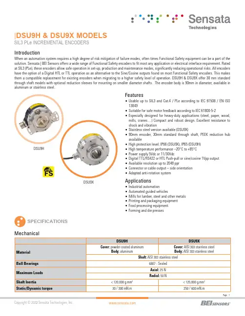
|DSU9H & DSU9X MODELSSIL3 PLe INCREMENTAL ENCODERS SPECIFICATIONSFeatures•Usable up to SIL3 and Cat.4 / PLe according to IEC 61508 / EN ISO 13849•Suitable for safe motor feedback according to IEC 61800-5-2•E specially designed for heavy-duty applications (steel, paper, wood,mills, cranes…) Compact and robust design. Excellent resistance to shock and vibration•Stainless steel version available (DSU9X)•90mm encoder, 30mm standard through shaft, PE E K reduction hub available•High protection level: IP66 (DSU9X), IP65 (DSU9H)•High temperature performance –20°C to +85°C •Power supply 5Vdc or 11/30Vdc•Digital TTL/RS422 or HTL Push-pull or sine/cosine 1Vpp output •Available resolution up to 2048 ppr•Connector or cable output – side orientation •Adapted anti-rotation systemIntroductionApplications•Industrial automation•Automated guided vehicles•Mills for lumber, steel and other metals •Printing and packaging equipment •Food processing equipment •Forming and die pressesDSU9XWhen an automation system requires a high degree of risk mitigation of failure modes, often times Functional Safety equipment can be a part of the solution. Sensata | BEI Sensors offers a wide range of Functional Safety encoders to fit most any application or electrical interface requirement. Rated at SIL3 (PLe), these encoders allow safe operation in set-up, production and maintenance modes, significantly reducing operational risks. All encoders have the option of a Digital HTL or TTL operation as an alternative to the Sine/Cosine outputs found on most Functional Safety encoders. This makes them a compatible replacement for existing encoders when migrating to a higher safety level of operation. DSU9H & DSU9X offer 30 mm standard through shaft models with optional reduction sleeves for mounting on smaller diameter shafts. The encoder body is 90mm in diameter, available in aluminum or stainless steel.(A)Continuous max. speed – ½ max. load – according to ISO 281: 1990, L10(B)Device must be supplied by a Class 2, LPS or SELV limited energy source.(C) UL listed:Electrical ConnectionsNote: All connections are UL certified, except G3 and GP RESOLUTIONS1024 2048DSU9H – radial cable and 20mm reduction hubDSU9X- radial M23 connector - IP66 optionCOUPLING INTERFACE Stator coupling kit M9445/045Tether arm kit M9445/046For a safe installation according to the required safety level needed in the application, refer to the user safety User Manual.The safety User Manual provides the technical information (drawings, electrical data, etc...) for a safe integration.A quick installation guide is provided with each encoder for use by the technician who installs the device on the equipment.GENERAL NOTESORDERING OPTIONSContact the factory for special versions, ex: resolution, connection, flange...* Parts mounted on encoder and fasteners included in the encoder box.AGENCY APPROVALS & CERTIFICATIONSBEI Sensors SASSensata TechnologiesEspace Européen de l’Entreprise9, rue de CopenhagueB.P. 70044 SchiltigheimF 67013 Strasbourg CedexTélFaxMailWeb: +33 (0)3 88 20 80 80: +33 (0)3 88 20 87 87:****************************: Americas+1 (800) 350 2727*******************Europe, Middle East & Africa +33 (3) 88 20 8080****************************Asia Pacific*************************.com China +86 (21) 2306 1500Japan +81 (45) 277 7117Korea +82 (31) 601 2004India +91 (80) 67920890Rest of Asia +886 (2) 27602006 ext 2808Page 7CONTACT USSensata Technologies, Inc. (“Sensata”) data sheets are solely intended to assist designers (“Buyers”) who are developing systems that incorporate Sensata products (also referred to herein as “components”). Buyer understands and agrees that Buyer remains responsible for using its independent analysis, evaluation and judgment in designing Buyer’s systems and products. Sensata data sheets have been created using standard laboratory conditions and engineering practices. Sensata has not conducted any testing other than that specifically described in the published documentation for a particular data sheet. Sensata may make corrections, enhancements, improvements and other changes to its data sheets or components without notice.Buyers are authorized to use Sensata data sheets with the Sensata component(s) identified in each particular data sheet. HOWEVER, NO OTHER LICENSE, EXPRESS OR IMPLIED, BY ESTOPPEL OR OTHERWISE TO ANY OTHER SENSATA INTELLECTUAL PROPERTY RIGHT, AND NO LICENSE TO ANY THIRD PARTY TECHNOLOGY OR INTELLECTUAL PROPERTY RIGHT, IS GRANTED HEREIN. SENSATA DATA SHEETS ARE PROVIDED “AS IS”. SENSATA MAKES NO WARRANTIES OR REPRESENTATIONS WITH REGARD TO THE DATA SHEETS OR USE OF THE DATA SHEETS, EXPRESS, IMPLIED OR STATUTORY, INCLUDING ACCURACY OR COMPLETENESS. SENSATA DISCLAIMS ANY WARRANTY OF TITLE AND ANY IMPLIED WARRANTIES OF MERCHANTABILITY, FITNESS FOR A PARTICULAR PURPOSE, QUIET ENJOYMENT, QUIET POSSESSION, AND NON-INFRINGEMENT OF ANY THIRD PARTY INTELLECTUAL PROPERTY RIGHTS WITH REGARD TO SENSATA DATA SHEETS OR USE THEREOF.All products are sold subject to Sensata’s terms and conditions of sale supplied at SENSATA ASSUMES NO LIABILITY FOR APPLICATIONS ASSISTANCE OR THE DESIGN OF BUYERS’ PRODUCTS. BUYER ACKNOWLEDGES AND AGREES THAT IT IS SOLELY RESPONSIBLE FOR COMPLIANCE WITH ALL LEGAL, REGULATORY AND SAFETY-RELATED REQUIREMENTS CONCERNING ITS PRODUCTS, AND ANY USE OF SENSATA COMPONENTS IN ITS APPLICATIONS, NOTWITHSTANDING ANY APPLICATIONS-RELATED INFORMATION Made in FranceACCESORIES。
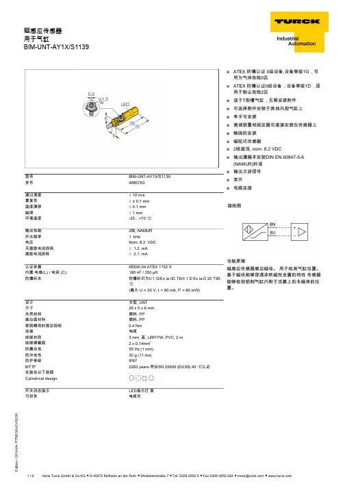
T 08:30:42+02:00型号BIM-UNT-AY1X/S1139货号4685763通过速度ð 10 m/s 重复性ï ± 0.1 mm 温度漂移ð 0.1 mm 磁滞ð 1 mm环境温度-25…+70 °C 输出性能2线, NAMUR 开关频率 1 kHz电压Nom. 8.2 VDC 无激励电流损耗ð 1.2 mA 激励电流损耗ï 2.1 mA认证依据KEMA 04 ATEX 1152 X 内置 电感(L ) / 电容 (C )180 nF / 350 µH防爆标志防爆标识为II 1 G/Ex ia IIC T6/II 1 D Ex ia D 20 T95°C(最大 U = 20 V, I = 60 mA, P = 80 mW)设计方型, UNT 尺寸28 x 5 x 6 mm 外壳材料塑料, PP 感应面材料塑料, PP 紧固螺母的固定扭矩0.4 Nm 连接电缆线缆材质3 mm, 蓝, Lif9YYW, PVC, 2 m线缆横截面2 x 0.14mm 防震动性55 Hz (1 mm)防冲击性30 g (11 ms)防护等级IP67MTTF2283 years 符合SN 29500 (Ed.99) 40 °C认证安装在以下剖面.Cylindrical design E N K F 开关状态指示LED指示灯 黄可供货电缆夹sATEX 防爆认证 II组设备,设备等级1G,可用为气体危险0区sATEX 防爆认证II组设备,设备等级1D,适用于粉尘危险2区s 适于T型槽气缸,无需安装附件s 可选择附件安装于其他外型气缸上s 单手可安装s 微调装置和固定器可直接安装在传感器上s 稳固的安装s 磁阻式传感器s 2线直流, nom. 8.2 VDCs输出遵循本安型DIN EN 60947-5-6(NAMUR)标准s输出方波信号s 常开s电缆连接接线图功能原理磁感应传感器感应磁场。

e-mail:**************For latest product manuals: TXDIN1600SSmart Powered Strain Bridge/Load Cell ConditionerShop online at User’s G ui d e***********************Servicing North America:U.S.A. Omega Engineering, Inc.Headquarters: Toll-Free: 1-800-826-6342 (USA & Canada only)Customer Service: 1-800-622-2378 (USA & Canada only)Engineering Service: 1-800-872-9436 (USA & Canada only)Tel: (203) 359-1660 Fax: (203) 359-7700e-mail:**************For Other Locations Visit /worldwideThe information contained in this document is believed to be correct, but OMEGA accepts no liability for any errors it contains, and reserves the right to alter specifications without notice.Important -follow the instructions can cause severe injuries and damage.This product is suitable for environment Installation category II pollution degree. The product is classed as "PERMANENTLY CONNECTED EQUIPMENT", and must be DIN rail mounted, inside a suitable enclosure providing environmental protection to IP65 or greater.DC supply must be derived from a local supply and not a distribution system.To maintain CE EMC requirements , input and DC supply wires must be less than 30 met must be made to repair this product. Faulty units must be returned to supplier for repair. This product must be installed by a qualified person. All electrical wiring must be carried out in accordance with the appropriate regulations for the place of installation. Before attempting any electrical connection work, please ensure all supplies are Every effort has been taken to ensure the accuracy of this document, however we do not accept responsibility for damage, injury, loss or expense resulting from errors and omissions, and we reserve the right of amendment OPERATIONRECEIVE AND UNPACKINGPlease inspect the packaging and instrument thoroughly for any signs of transit damage. If the instrument has been damaged, please notify your supplier immediately.CLICK USB_SPEEDLINK HELP BUTTON FOR FULL GUIDE TO CONFIGURATIONCONFIGURATIONThis product is configured using the USB port of a PC running USB_Speed_Link software, available from your suppliers. During configuration the product is powered direct from the usb port, removing the need for additional power. If the user wishes to monitor live process data during configuration, then power must be applied. Note the input and USB port of the device share the same ground, therefore care must be taken to ensure isolation between PC and input circuit. This is best achieved by using a portable laptop or notebook PC. USB_Speed_Link software is provided with detailed help menu to guide the user through the simple configuration procedure. Unless specified at the time of order this product is supplied with the default configuration listed below.Factory default:Model (sensor)= “ “Calibration Factor = 2 mV/V Balance = 0.0Sample Rate = 10 SPS Filter = 0 (off)Scale = 2 points Process Range = (0 to100)Units = “PV”Process Output = (0 to 100)Output range = (4 to 20) mA Tare Setpoint = 0.0Tare Offset = 0.0Tag = “ “Button Tare Lock off Trim Buttons Lock off1.0 TURN OFF SUPPLY BEFORE WORKING ON ANY ELECTRICAL CONNECTION.2.0 SUPPLY IS OVER VOLTAGE PROTECTED AND FUSED WITH INTERNAL RESSETTBLE FUSE.ELECTRICAL INSTALLATIONCONNECTIONFor cable length < 3 Met ers no screen or twist pair required.Use recommended types for cable length (3 to 30) met ers .Screw DriverScreened CableMECHANICAL INSTALLATIONStyle Material Terminals Cable ColorDIN 43880 (1 module width)Polyamide 6.6 self extinguishing Screw terminal 2.5 mm Max Gr ayMOUNTINGScrew driverEN50022 DIN RAIL70°CTOP17.5 mm 1211121098790mmPUSH BUTTON CONFIGURATIONTwo trim buttons are provided on the front panel –blue = low trim, red = high trim. The trim buttons allow the operator to trim the device against a live input signal (similar to the “Active Range” range buttons available in the configuration software). The trim buttons operate as follows, please note both trim points operate independently, if desired only one trim point may be set, for example the low (blue) to correct a zero offset :-With the input settled at the required high or low trim point, press and keep button pressed -the range light will go off for a few seconds then flash at a fast rate before returning to a steady state. Release button. Trim operation complete. Output trims to levels preset in the software configuration.The tare may be set remotely by using contacts 9 and 12 connected to a volt free contact. The actual tare setpoint can be pre-programmed into the device during configuration.On tare contact closure corrections within the device in the form of a offset to set the present input signal to represent the preset tare setpoint value.OMEGA’s policy is to make running changes, not model changes, whenever an improvement is possible. T his affords ourcustomers the latest in technology and engineering.OMEGA is a trademark of OMEGA ENGINEERING, INC.© Copyright 2018 OMEGA ENGINEERING, INC. All rights reserved. T his document may not be copied, photocopied, reproduced, translated, or reduced to any electronic medium or machine-readable form, in whole or in part, without the prior written consent of OMEGA ENGINEERING, INC.FOR WARRANTY RETURNS, please have thefollowing information available BEFORE contactingOMEGA:1. P urchase Order number under which the productwas PURCHASED,2. M odel and serial number of the product underwarranty, and3.Repair instructions and/or specific problemsrelative to the product.FOR NON-WARRANTY REPAIRS, consult OMEGA for current repair charges. Have the following information available BEFORE contacting OMEGA:1.Purchase Order number to cover the COST of the repair,2.Model and serial number of the product, and 3.Repair instructions and/or specific problems relative to the product.RETURN REQUESTS/INQUIRIESDirect all warranty and repair requests/inquiries to the OMEGA Customer Service Department. BEFORE RET URNING ANY PRODUCT (S) T O OMEGA, PURCHASER MUST OBT AIN AN AUT HORIZED RET URN (AR) NUMBER FROM OMEGA’S CUST OMER SERVICE DEPART MENT (IN ORDER T O AVOID PROCESSING DELAYS). The assigned AR number should then be marked on the outside of the return package and on any correspondence.T he purchaser is responsible for shipping charges, freight, insurance and proper packaging to preventbreakage in transit.WARRANTY/DISCLAIMEROMEGA ENGINEERING, INC. warrants this unit to be free of defects in materials and workmanship for a period of 61 months from date of purchase. OMEGA’s WARRANTY adds an additional one (1) month grace period to the normal five (5) year product warranty to cover handling and shipping time. This ensures that OMEGA’s customers receive maximum coverage on each product.If the unit malfunctions, it must be returned to the factory for evaluation. OMEGA’s Customer Service Department will issue an Authorized Return (AR) number immediately upon phone or written request. Upon examination by OMEGA, if the unit is found to be defective, it will be repaired or replaced at no charge. OMEGA’s WARRANT Y does not apply to defects resulting from any action of the purchaser, including but not limited to mishandling, improper interfacing, operation outside of design limits, improper repair, or unauthorized modification. T his WARRANT Y is VOID if the unit shows evidence of having been tampered with or shows evidence of having been damaged as a result of excessive corrosion; or current, heat, moisture or vibration; improper specification; misapplication; misuse or other operating conditions outside of OMEGA’s control. Components in which wear is not warranted, include but are not limited to contact points, fuses, and triacs.OMEGA is pleased to offer suggestions on the use of its various products. However, OMEGA neither assumes responsibility for any omissions or errors nor assumes liability for any damages that result from the use of its products in accordance with information provided by OMEGA, either verbal or written. OMEGA warrants only that the parts manufactured by the company will be as specified and free of defects. OMEGA MAKES NO OTHER WARRANTIES OR REPRESENTATIONS OF ANY KIND WHATSOEVER, EXPRESSED OR IMPLIED, EXCEPT THAT OF TITLE, AND ALL IMPLIED WARRANTIES INCLU DING ANY WARRANTY OF MERCHANTABILITY AND FITNESS FOR A PARTICU LAR PU RPOSE ARE HEREBY DISCLAIMED. LIMITATION OF LIABILITY: The remedies of purchaser set forth herein are exclusive, and the total liability of OMEGA with respect to this order, whether based on contract, warranty, negligence, indemnification, strict liability or otherwise, shall not exceed the purchase price of the component upon which liability is based. In no event shall OMEGA be liable for consequential, incidental or special damages.CONDITIONS: Equipment sold by OMEGA is not intended to be used, nor shall it be used: (1) as a “Basic Component” under 10 CFR 21 (NRC), used in or with any nuclear installation or activity; or (2) in medical applications or used on humans. Should any Product(s) be used in or with any nuclear installation or activity, medical application, used on humans, or misused in any way, OMEGA assumes no responsibility as set forth in our basic WARRANT Y /DISCLAIMER language, and, additionally, purchaser will indemnify OMEGA and hold OMEGA harmless from any liability or damage whatsoever arising out of the use of theProduct(s) in such a manner.Where Do I Find Everything I Need forProcess Measurement and Control?OMEGA…Of Course!Shop online at TEMPERATUREM U Thermocouple, RTD & Thermistor Probes, Connectors,Panels & AssembliesM U Wire: Thermocouple, RTD & ThermistorM U Calibrators & Ice Point ReferencesM U Recorders, Controllers & Process MonitorsM U Infrared PyrometersPRESSURE, STRAIN AND FORCEM U Transducers & Strain GagesM U Load Cells & Pressure GagesM U Displacement TransducersM U Instrumentation & AccessoriesFLOW/LEVELM U Rotameters, Gas Mass Flowmeters & Flow ComputersM U Air Velocity IndicatorsM U Turbine/Paddlewheel SystemsM U Totalizers & Batch ControllerspH/CONDUCTIVITYM U pH Electrodes, Testers & AccessoriesM U Benchtop/Laboratory MetersM U Controllers, Calibrators, Simulators & PumpsM U Industrial pH & Conductivity EquipmentDATA ACQUISITIONM U Communications-Based Acquisition SystemsM U Data Logging SystemsM U Wireless Sensors, Transmitters, & ReceiversM U Signal ConditionersM U Data Acquisition SoftwareHEATERSM U Heating CableM U Cartridge & Strip HeatersM U Immersion & Band HeatersM U Flexible HeatersM U Laboratory HeatersENVIRONMENTALMONITORING AND CONTROLM U Metering & Control InstrumentationM U RefractometersM U Pumps & TubingM U Air, Soil & Water MonitorsM U Industrial Water & Wastewater TreatmentM U pH, Conductivity & Dissolved Oxygen InstrumentsM5674/0218。
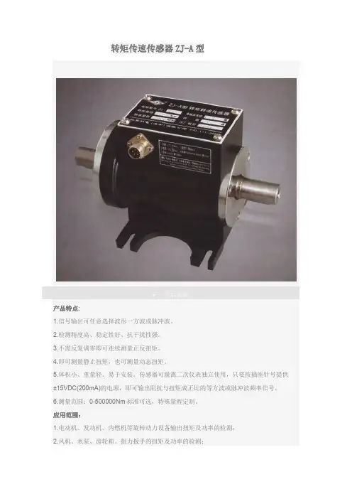
转矩传速传感器ZJ-A型产品参数产品特点:1.信号输出可任意选择波形一方波或脉冲波。
2.检测精度高、稳定性好、抗干扰性强。
3.不需反复调零即可连续测量正反扭矩。
4.即可测量静止扭矩,也可测量动态扭矩。
5.体积小、重量轻、易于安装。
传感器可脱离二次仪表独立使用,只要按插座针号提供±15VDC(200mA)的电源,即可输出阻抗与扭矩成正比的等方波或脉冲波频率信号。
6.测量范围:0-500000Nm标准可选,特殊量程定制。
应用范围:1.电动机、发动机、内燃机等旋转动力设备输出扭矩及功率的检测;2.风机、水泵、齿轮箱、扭力扳手的扭矩及功率的检测;3.铁路机车、汽车、拖拉机、飞机、船泊、矿山机械中的扭矩及功率的检测;4.可用于污水处理系统中的扭矩及功率的检测;5.可用于制造粘度计;6.可用于过程工业和流程工业中;基本原理:转矩的测量:采用应变片电测技术,在弹性轴上组成应变桥,向应变桥提供电源即可测得该弹性轴受扭的电信号。
将该应变信号放大后,经过压/频转换,变成与扭应变成正比的频率信号。
工作过程:将专用的扭矩应变片用应变胶粘帖在被测弹性轴上并组成应变桥,向应变桥提供电源即可测得该弹性轴受扭的电信号。
将扭矩传感器应变信号放大后,经过压/频转换,变成与扭应变成正比的频率信号。
本系统的能源输入及信号输出是由两组带间隙的特殊环形变压器承担的,因此实现了无接触的能源及信号传递功能。
向传感器提供±15VDC电源,激磁电路中的晶体振荡器产生400Hz的方波,经过功率放大器即产生交流激磁功率电源,通过能源环形变压器T1从静止的初级线圈传递至旋转的次级线圈,得到的交流电源通过轴上的整流滤波电路得到±5V的直流电源,该电源做运算放大器的工作电源;由基准电源与双运放组成的高精度稳压电源产生±4.5V的精密直流电源,该电源及作为电桥电源,有座位放大器即V/F转换器的工作电源。
当弹性轴受扭时应变桥检测得到的mV级的应变信号通过仪表放大器放大成1.5v±1v的强信号,再通过V/F转换器变换成频率信号,通过信号环形变压器T2从旋转的初级线圈传递至静止次级线圈,在经过传感器外壳上的信号处理电路滤波、整形即可得到与弹性轴承受的扭矩成正比的频率信号,该信号为TTL电平,即可提供给专用二次仪表或频率计显示,也可直接送计算机处理。
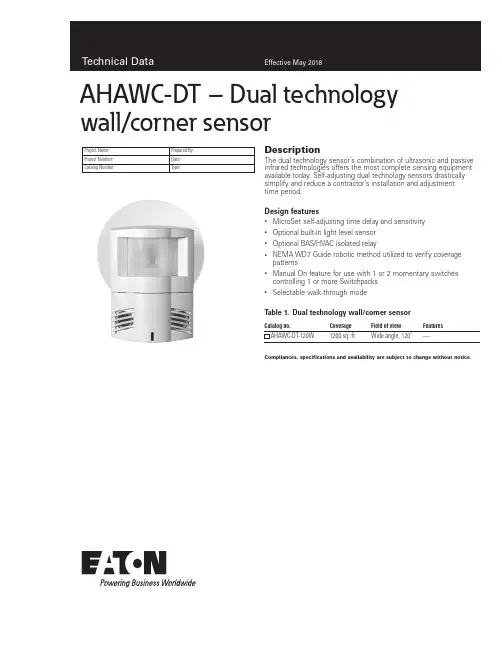
DescriptionThe dual technology sensor’s combination of ultrasonic and passive infrared technologies offers the most complete sensing equipment available today. Self-adjusting dual technology sensors drastically simplify and reduce a contractor’s installation and adjustment time period.Design features• MicroSet self-adjusting time delay and sensitivity • Optional built-in light level sensor • Optional BAS/HVAC isolated relay•NEMA WD7 Guide robotic method utilized to verify coverage patterns•Manual On feature for use with 1 or 2 momentary switches controlling 1 or more Switchpacks •Selectable walk-through modeT able 1. Dual technology wall/corner sensorProject Name:Prepared By:Project Number:Date:Catalog Number:Type:AHAWC-DT – Dual technology wall/corner sensorCompliances, specifications and availability are subject to change without notice.Catalog no.CoverageField of viewFeaturesAHAWC-DT-120W 1200 sq. ft Wide angle, 120˚—2EATON /wiringdevices T able 2. SpecificationsProject Name:Prepared By:Project Number:Date:Catalog Number:Type:Compliances, specifications and availability are subject to change without notice.W (White)Technical DataEffective May 2018AHAWC-DT – Dual technology wall/corner sensor The AHAWC-DT combines Ultrasonic (US) and Passive Infrared (PIR) sensor technologies to monitor a room for occupancy to delivermaximum energy savings and ensure the greatest sensitivity and coverage for tough application without the threat of false triggers. PIR is used to turn the lights ON and then either or both technologies are used to keep the lights ON. The sensor includes MicroSet self-adaptive technology that continuously self-adjusts sensitivity and time delay in real-time, maximizing the potential energy savings that are available in particular application. In automatic on mode, the lights turn ON when a person enters the room. In manual-on mode, the lights are turned ON by activating a momentary switch (model # GMDS-*) that is connected to the sensor.ApplicationsCatalog no.AHAWC-DT seriesTechnologyPassive Infrared (PIR) and Ultrasonic (US)Power RequirementsInput0-30 VDC from Greengate Switchpack or Greengate System Maximum current needed is 25 mA per sensor OutputOpen collector output to switch up to ten Greengate Switchpacks Isolated Form C Relay Ratings: 1A 30 VDC/V/AC Time DelaysSelf-Adjusting, 15 seconds/test, 5, 10, 15, 30 minutesLight Level Sensing 0 to 300 foot-candlesOperating EnvironmentTemperature: 32°F - 104°F (0°C - 40°C)Relative humidity: 20% to 90%, non-condensing (For indoor use only)Housing Durable, injection molded housing. Polycarbonate resin complies with UL 94V-0Size4.4”H x 3.4”W x 2”D (112mm x 86.4mm x 50.8mm)Mounting Mounts directly to ceiling tile, to a 4” square box and round mud ring or to 4” octagon boxLED Indicators Red LED for PIR detection; Green LED for Ultrasonic detection StandardsFCC Compliant cULus ListedT able 3. Color informationProject Name:Prepared By:Project Number:Date:Catalog Number:Type:Wiring diagramsFigure 1. AHAWC-DT -120W ModelAHAWC-DT – Dual technology wall/corner sensorTechnical DataEffective May 2018Coverage3EATON /wiringdevices Compliances, specifications and availability are subject to change without notice.Technical DataEffective May 2018Certifications & compliancesCompliances, specifications and availability are subject to change without notice.KEY:cULusRoHSElectrical Sector203 Cooper CirclePeachtree City, GA 30269United States /wiringdevicesElectrical Sector Canada Operations 5925 McLaughlin RoadMississauga, Ontario, L5R 1B8CanadaEatonCanada.ca/wiringdevicesElectrical Sector Mexico Operations Carr. Tlalnepantla -Cuautitlan Km 17.8 s/n Col. Villa Jardin esq.Cerrada 8 de MayoCuautitlan, Mexico CP 54800Mexico Eaton.mx/wiringdevicesEaton is a registered trademark. All other trademarks are property of their respective owners.Eaton1000 Eaton Boulevard Cleveland, OH 44122United States © 2018 EatonAll Rights Reserved Printed in USAPublication No. TD620044EN May 2018Project Name:Prepared By:Project Number:Date:Catalog Number:Type:AHAWC-DT – Dual technology wall/corner sensor Controls。
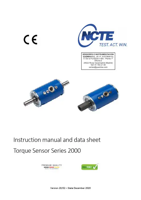
Instruction manual and data sheet Torque Sensor Series 2000SENSORES E INSTRUMENTACION GUEMISA S.L.()N.I.F.: B-87969416C\ De la Fundición 4 Bis - Planta 1ºOficina-228522 Rivas Vaciamadrid (Madrid)Telf. 91 764 21 00******************Copyright ©NCTE AG® Torque Sensor Series 2000 Instruction Manual and Data Sheet. This instruction manual is property of NCTE AG®,D-82041 OberhachingUnauthorized duplication, even in part, is not permitted.State: December 2020Instruction manual1 General (5)1.1 Customer service address (5)1.2 Warranty (5)1.3 Scope of delivery (5)1.4 Declaration of conformity (6)2 Safety (7)2.1 Intended use (7)2.2 Recalibration and duration of use (7)2.3 Structural change (7)2.4 Training of the operating personnel (7)2.5 Transport and handling (7)3 Torque Sensor Series 2000 (8)3.1 Short description (8)3.2 Assembly and disassembly (8)3.3 Interface description (8)3.4 Starting up (8)3.5 Operation during regular mode (9)3.6 Irregular operation, actions in case of failures (9)3.7 Safety instructions (9)3.8 Shaft preservation (9)3.9 Service, maintenance and repair (9)3.10 Disposal (9)Data sheet1 Key Facts (10)2 Torque ranges (10)3 Load characteristics (11)4 Technical characteristics (11)5 EMV Emission data (12)6 Dimensions (13)7 Wiring diagram (14)8 Sensor wiring (14)9 Order options (14)10 Accessories (15)Instruction manual.1GeneralDear customers,Thank you for your decision to buy our sensor products. You have chosen a high quality and extremely precise torque measuring system.This manual contains all the information necessary for you and the installation, operating and maintenance personnel to use your measuring system under the intended conditions of use. It contains important information to ensure proper and safe installation and operation.For these reasons, the Instruction manual must always be available at the place of use of the torque measuring system and always ready to hand.We reserve the right to make changes in the course of product improvements. We try to maintain compatibility with previous versions. All information without guarantee subject to technical changes.For further questions, we are of course also available after the purchase at any time.Please use our contact address1.1Customer service addressNCTE AGRaiffeisenalle 3D-82041 OberhachingPhone: +49 (0)89 665 619 0Email: *************Web: https:///1.2WarrantyThe warranty period is 12 months from the date of delivery from the factory, provided that the product is used in accordance with its intended purpose, in compliance with the maintenance and calibration regulations and the General Terms and Conditions of Business.You can find these, current instruction manuals and data sheets on:https:///en/standard-products/#1.3Scope of deliveryThe torque sensor system consists of a calibrated sensor, signal acquisition / -processing integrated in the housing, a 5 m long connection cable with plug (Binder plug no. 99-0426-10-08) and keystone (round shaft) or square sleeve (square shaft).Enclosed you will find the corresponding calibration certificate and the warning notes.1.4Declaration of conformityThe manufacturerNCTE AGRaiffeisenalle 3D-82041 Oberhachinghereby declares that the following productProduct designation: Torque sensor series 2000Trade designation: Series 2000Model names: 2100-2.5 2200-2.52100-5 2200-52100-7.5 2200-7.52100-15 2200-17.52100-60 2200-752100-140 2200-1752200-2502100-400 2200-500conforms to the requirements of the EMC Directive 2014/30/EU – including its amendments in force at the time of this declaration.The following harmonized standards were applied:EN 61000-6-2:2019-11EN 61000-6-4:2020-09EN 61326-1:2013-07EN 61326-1:2018-09 (Draft)The following national laws, standards and specifications were applied:Electromagnetic compatibility law – EMVGPlace: OberhachingDate: December 15th 2020______________________________ ______________________________Dr. Jürgen Uebbing, CEO Ms. Verena Graf, COO______________________________Mr. Bernhard Mayr, Technical Director2SafetyPlease note the enclosed sheet on the warning notes.2.1Intended useThe sensors of the series 2000 are designed exclusively for measuring torque and/or speed. The respective load range can be taken from the data sheet and must not be exceeded.Proper use also includes compliance with the commissioning, assembly, operating, ambient and maintenance conditions specified by the manufacturer.Any use beyond these is considered improper. The manufacturer is not liable for any damage resulting from such use.2.2Recalibration and duration of useA factory recalibration should be executed annually. See the corresponding label on the sensor.This recalibration can be carried out quickly and easily by NCTE AG.Please contact us.If the sensor is used within the limits of its intended use and regularly calibrated, the sensor's operating life is unlimited.2.3Structural changeUnauthorized conversions or changes to the torque measuring system are prohibited for safety reasons and lead to the immediate expiration of the warranty claims.2.4Training of the operating personnelAssembly, commissioning and maintenance personnel must have read and understood the complete operating instructions, especially Chapter “2 Safety". The operator is recommended to have this confirmed in writing.2.5Transport and handlingDuring handling, storage and transport, make sure that the sensor is not exposed to strong magnetic or electromagnetic fields (e.g. degaussing coils).3Torque Sensor Series 2000The Series 2000 provides the easiest and most cost-effective entry into torque measurement technology.3.1Short descriptionThe series is mainly used in test stands, automation processes, production lines e.g. end-of-line tests and teaching.Torque measurement is possible both statically and dynamically. The mechanical connection is made via a square shaft (series 2100) or round shaft (series 2200).The Series 2000 provides an analogue output signal with 0-5V.The sensor is delivered as a ready-to-connect unit including 5m cable, keystones (round shaft) and calibration certificate.3.2Assembly and disassemblyWhen mounting the sensor, make sure that the measuring shaft is exactly aligned with the connecting shafts (corresponding couplings can be found in the accessories). It must then be possible to push the key adapters / square ends of the connection shafts onto the key adapter connections / square connections of the sensor without any effort. No force must be exerted on the housing in the axial direction during fastening. The sensor can be secured against rotation by means of the flat surface (optional sensor holder). The cable length must not exceed 5m. Using a cable other than the one supplied by NCTE or an identical cable with a different cable length may impair the function of the sensor system.The disassembly may only be done without applying torque to the measuring shaft.3.3Interface descriptionMechanical interfaces:For power transmission, adapter connections are provided at both ends of the keystone round shafts. In respect to square sensors, the shaft has square ends.Electrical interface:A socket for power supply and signal output is attached to the upper side of the housing.(Pin assignment see Chapter “7 Wiring diagram")3.4Starting upAfter mounting the sensor, the following must be observed:∙Switch on power supply and check voltage value.(Voltage peaks at the sensor must be avoided, devices must be checked accordingly beforeconnection to the sensor)∙Connect the sensor to the power supply. (using the cable supplied).∙Record the output signal of the sensor with high resistance.(e.g. A/D converter, oscilloscope, PC measuring card)∙Record output signal in mechanically unloaded state of the sensor.3.5Operation during regular modeOptimal measuring values are achieved when the sensor is used while maintaining the specific nominal torque. If the permissible operating conditions are observed, the sensor operates trouble-free and maintenance-free.3.6Irregular operation, actions in case of failuresIf the sensor is mechanically overloaded (e.g. if the maximum permissible longitudinal force or torque limit is exceeded or if there are strong vibrations), the sensor may be damaged and the signal output may be distorted. In this case do not open the device. Contact NCTE AG directly.3.7Safety instructionsThe following safety instructions should be followed for smooth operation:∙Opening the sensor or even single screws is not allowed.∙The shaft retaining rings on the shaft ends must not be loosened.∙The fastening nut of the plug must not be loosened or tightened.∙Only use power supplies safely disconnected from the mains voltage.∙Regarding the electrical and mechanical load of the sensor, the specifications according to the sensor-specific nameplate and the table in Chapter “4 Technical characteristics” must be observed.∙The sensor is not to be used as support bearing. The existing fastening options serve exclusively to secure the housing against twisting.∙To protect your system, we recommend increasing the torque over several stages.3.8Shaft preservationThe shafts are protected on both sides with a film of anti-corrosion wax. We recommend to leave the protection permanently. If technically necessary, remove the protective film with spirit/ethanol.3.9Service, maintenance and repairAs part of your test and measurement equipment management, we recommend regular inspection of your test and measurement equipment. Please also observe the relevant standards and guidelines. Maintenance plan by NCTE AGCalibration: Every 12 monthsCheck the wiring, connectors and shaft: Every 12 monthsRepairs and recalibrations can only be carried out by NCTE AG personnel.3.10DisposalThe device must be returned to NCTE AG, Raiffeisenallee 3, D-82041 Oberhaching for disposal.Data sheet. 1Key Facts2Torque rangesNote: Series 2100 sensor versions are calibrated to nominal torque. However, the absolute operating limits are as shown in the table above. Do not exceed the specified magnitude of the limit torques for unidirectional and bidirectional loading.Note: In case of overload, the sensor leads to a measurement offset. In this case the sensor must be recalibrated at NCTE AG. The sensor may only be operated within the specified nominal torque range.3Load characteristicsAny irregular stress (bending moment, transverse or axial force, exceeding the nominal torque) up to the specified static load limit is only permissible as long as none of the other stresses can occur. Otherwise the limit values must be reduced. If 30 % of the limit bending moment and 30 % of the limit transverse force are present in each case, only 40 % of the axial force is permissible, whereby the nominal torque must not be exceeded.4Technical characteristics1 Specified values only apply to direct axial force on the shaft. If the axial force acts on the circlip, only 50 % of the force is permissible.2 Specified values only apply to direct axial force on the shaft. If the axial force acts on the circlip, only 50 % of the force is permissible.3The accuracy class means that the linearity deviation as well as the circulation modulation, individually, are each less than or equal to the value specified as the accuracy class. The accuracy class must not be confused with a classification according to DIN 51309 or EA-10/14.4 %ME: Related to the measuring range.5 The exact sensor-specific values can be found in the calibration certificate supplied.EMV immunity and emitted interference (DIN EN IEC 61000-6-2 / DIN EN IEC 61000-6-4 / DIN EN 61326-1)6 Wiring connected.6 DimensionsSeries 2200For high alternating loads, torque transmission by positive and frictional locking via a suitable fit or couplingis recommended.2200 (TM-HR-Rd)Round drive2100 (TM-HR-Sq)Square drivePotentiometer for offset adjustmentKeystone7 Wiring diagramConnectorPower supply and outputs8 Sensor wiringThe grey and blue wires are not required.The blue wire is not required.9 Order optionsWe would be pleased to provide you with further information about serial products in a personal contact underPhone: +49 (0)89 66 56 19 30 or by e-mail: *************.10AccessoriesBracket1 2.5 – 17.5 Nm (Art. No.: 400006081)2 75 – 250 Nm (Art. No.: 400006082)Readout unit1 Order number 400010-ATS001 The NCTE readout unit is a multifunctional readout unit fora USB interface.Couplingscoupling types Used for D2 max.You can obtain further or additional accessories and special requests in a personal discussion with your contact person for series products by calling +49 (0)89 66 56 19 30 or by e-mail: *************.Your experts for magnetostrictive sensorsSENSORES E INSTRUMENTACION GUEMISA S.L.C\ La Fundición 4 Bis - P 1Oficina-2l ª28522 Rivas Vaciamadrid (Madrid)Telf. 91 764 21 00 email:******************。
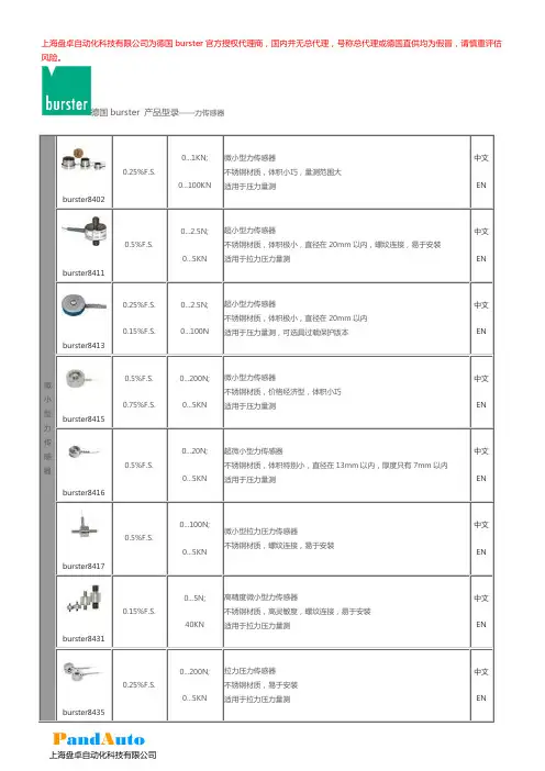
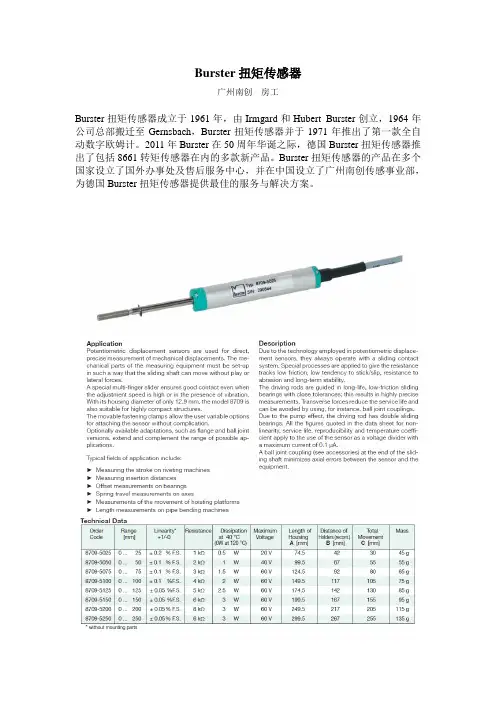
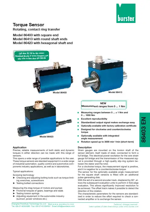
Burster扭矩传感器广州南创房工Burster扭矩传感器成立于1961年,由Irmgard和Hubert Burster创立,1964年公司总部搬迁至Gernsbach,Burster扭矩传感器并于1971年推出了第一款全自动数字欧姆计。
2011年Burster在50周年华诞之际,德国Burster扭矩传感器推出了包括8661转矩传感器在内的多款新产品。
Burster扭矩传感器的产品在多个国家设立了国外办事处及售后服务中心,并在中国设立了广州南创传感事业部,为德国Burster扭矩传感器提供最佳的服务与解决方案。
Burster扭矩传感器技术参数以《OIML60号国际建议》92年版为基础,最新具体变化可查看《JJG669—12 Burster广州南创传感事业部检定规程》Burster扭矩传感器Model 8431: 8431-5:0-5N 0.5kHz(谐振频率) 8431-10:0-10N 1.8kHz(谐振频率)8431-20:0-20N 2.0kHz(谐振频率)8431-50:0-50N 5.7kHz(谐振频率)8431-100:0-100N 6.5kHz(谐振频率)8431-200:0-200N 13.8kHz(谐振频率)8431-500:0-500N 20.5kHz(谐振频率)8431-1000:0-1kN 21.0kHz(谐振频率)8431-2000:0-2kN 23.9kHz(谐振频率)8431-5000:0-5kN 50.0kHz(谐振频率)8431-10000:0-10kN8431-20000:0-20kN8431-40000:0-40kNBurster扭矩传感器Model 8432: 8432-2.5:0-2.5N 0.1kHz(谐振频率) (过载保护) 8432-5: 0-5N 0.5kHz(谐振频率)8432-10: 0-10N 1.8kHz(谐振频率)8432-20: 0-20N 2.0kHz(谐振频率)8432-50: 0-50N 5.7kHz(谐振频率)8432-100:0-100N 6.5kHz(谐振频率)8432-200:0-200N 13.8kHz(谐振频率)8432-500:0-500N 20.5kHz(谐振频率)8432-1000:0-1kN 21.0kHz(谐振频率)8432-2000:0-2kN 23.9kHz(谐振频率)Burster扭矩传感器Model 8435: 8435-5200:0-200N 5,0kHz(频率) 8435-5500:0-500N 9,0kHz(频率)8435-6001:0-1000N 14,0kHz(频率)8435-6002:0-2000N 18,0kHz(频率)8435-6005:0-5000N 22,0kHz(频率)Burster扭矩传感器Model 8438: 8438-5005:0-5N8438-5010:0-10N8438-5020:0-10N8438-5050:0-50N8438-5100:0-100N8438-5200:0-200N8438-5500:0-500N8438-6001:0-1kN8438-6002:0-2kN8438-6005:0-5kN8438-6010:0-10kN8438-6020:0-20kN8438-6050:0-50kN8438-6100:0-100kN8438-6200:0-200kNBurster扭矩传感器Model 8451: 8451-5500:0-0.5kN8451-6001:0-1kN8451-6002:0-2kN8451-6005:0-5kN8451-6010:0-10kN8451-6020:0-20kNBurster扭矩传感器3.Load Cells in various designsModel 8510: 8510-5001:0-1N 5N(Overload protection)8510-5002:0-2N 10N(Overload protection)8510-5005:0-5N 15N(Overload protection)8510-5010:0-10N 20N(Overload protection)8510-5020:0-20N 40N(Overload protection)Burster扭矩传感器Model 8511: 8511-5005:0-±5N8511-5010:0-±10N8511-5020:0-±20N8511-5050:0-±50N8511-5100:0-±100N8511-5200:0-±200N8511-5500:0-±500N8511-6001:0-±1000N8511-6002:0-±2000N德国Burster扭矩传感器Model 8523: 8523-20:0-20N 8523-50:0-50N8523-100:0-100N8523-200:0-200N8523-500:0-500N德国Burster扭矩传感器Model 8531: 8531-1000:0-1000N 8531-2000:0-2000N8531-5000:0-5000N德国Burster扭矩传感器Model 8524: 8524-5500:0-±0.5kN 8524-6001:0-±1kN8524-6002:0-±2kN8524-6005:0-±5kN8524-6010:0-±10kN8524-6020:0-±20kN8524-6050:0-±50kN8524-6100:0-±100kN8524-6200:0-±200kN德国Burster扭矩传感器Model 8526: 8526-5100:0-100N 8526-5200:0-200N8526-5500:0-500N8526-6001:0-1kN8526-6002:0-2kN8526-6005:0-5kN8526-6010:0-10kN8526-6020:0-20kN8526-6050:0-50kN8526-6100:0-100kN8526-6200:0-200kN德国Burster扭矩传感器Model 8527: 8527-5500:0-500N 8527-6001:0-1kN8527-6002:0-2kN8527-6005:0-5kN8527-6010:0-10kN8527-6020:0-20kN8527-6050:0-50kN8527-6100:0-100kN德国Burster扭矩传感器Model 86402: 86402-5006:0-±6Nm 86402-5012:0-±12Nm86402-5025:0-±25Nm86402-5063:0-±63Nm86402-5160:0-±160Nm86402-5500:0-±500Nm86402-6001:0-±1000Nm德国Burster扭矩传感器速度传感器:Velocity Sensor德国Burster扭矩传感器加速度传感器Model 89100 :13 ... 610 mm德国Burster扭矩传感器转动角传感器:Potentiometric Angle of Rotation Sensor Model 8820: up to 350°Rotary Speed Sensor Model 8821 :60 ... 360 imp./turnPrecision Angle of Rotation Sensor Model 88600 :up to 160。
Instruction ManualSelf-Contained, AC-Operated Sensors•Featuring EZ-BEAM ® technology for reliable sensing without the need for adjustments•Rectangular 25 mm plastic housing with 18 mm threaded mounting base in opposed, retroreflective, or fixed-field modes•Completely epoxy-encapsulated to provide superior durability, even in harsh sensing environments rated to IEC IP69K•Innovative dual-indicator system takes the guesswork out of sensor performance monitoring•20 V to 250 V ac (3-wire hookup); SPST solid-state switch output,maximum load 300 mAWARNING: Not To Be Used for Personnel ProtectionNever use this device as a sensing device for personnel protection. Doing so could lead to serious injury or death. This device does not include the self-checking redundant circuitry necessary to allow its use in personnel safety applications. A sensor failure or malfunction can cause either an energized or de-energized sensor output condition.ModelsFixed-Field Mode OverviewQ25 self-contained fixed-field sensors are small, powerful, infrared diffuse mode sensors with far-limit cutoff (a type of background suppression). Their high excess gain and fixed-field technology allow detection of objects of low reflectivity,while ignoring background surfaces.The cutoff distance is fixed. Backgrounds and background objects must always be placed beyond the cutoff distance.•9 m (30 ft) cable: add suffix "W/30" (for example, Q253E W/30).•4-pin Micro-style QD models: add suffix "Q1" (for example, Q253EQ1). A model with a QD connector requires a mating cable.Q25 AC SensorsOriginal Document121517 Rev. A28 January 2016121517Fixed-Field Sensing – Theory of OperationThe Q25FF compares the reflections of its emitted light beam (E) from an object back to the sensor's two differently aimed detectors, R1 and R2. See Figure 1 on page 2. If the near detector's (R1) light signal is stronger than the far detector's (R2) light signal (see object A in the Figure below, closer than the cutoff distance), the sensor responds to the object. If the far detector's (R2) light signal is stronger than the near detector's (R1) light signal (see object B in the Figure below, beyond the cutoff distance), the sensor ignores the object.The cutoff distance for model Q25FF sensors is fixed at 25, 50 or 100 millimeters (0.9 in, 1.9 in, or 3.9 in). Objects lying beyond the cutoff distance are usually ignored, even if they are highly reflective. However, under certain conditions, it is possible to falsely detect a background object (see Background Reflectivity and Placement on page 2).orCutoffNearDetectorFarDetectorEmitterObject is sensed if amount of light at R1is greater than the amount of light at R2Figure 1. Fixed-Field ConceptAxis Figure 2. Fixed-Field Sensing AxisIn the drawings and information provided in this document, the letters E, R1, and R2 identify how the sensor's three optical elements (Emitter "E", Near Detector "R1", and Far Detector "R2") line up across the face of the sensor. The location of these elements defines the sensing axis, see Figure 2 on page 2. The sensing axis becomes important in certain situations, such as those illustrated in Figure 5 on page 3 and Figure 6 on page 3.Device SetupSensing ReliabilityFor highest sensitivity, position the target for sensing at or near the point of maximum excess gain. See the Performance Curves section for excess gain curves. Sensing at or near this distance makes the maximum use of each sensor’s available sensing power. The background must be placed beyond the cutoff distance. Note that the reflectivity of the background surface also may affect the cutoff distance. Following these guidelines improves sensing reliability.Background Reflectivity and PlacementAvoid mirror-like backgrounds that produce specular reflections. A false sensor response occurs if a background surface reflects the sensor's light more to the near detector (R1) than to the far detector (R2). The result is a false ON condition (Figure 3 on page 3). Correct this problem by using a diffusely reflective (matte) background, or angling either the sensor or the background (in any plane) so the background does not reflect light back to the sensor (Figure 4 on page 3). Position the background as far beyond the cutoff distance as possible.An object beyond the cutoff distance, either stationary (and when positioned as shown in Figure 5 on page 3), ormoving past the face of the sensor in a direction perpendicular to the sensing axis, may cause unwanted triggering of the sensor if more light is reflected to the near detector than to the far detector. Correct the problem by rotating the sensor 90° (Figure 6 on page 3). The object then reflects the R1 and R2 fields equally, resulting in no false triggering. A better solution, if possible, may be to reposition the object or the sensor. - Tel: +1-763-544-3164P/N 121517 Rev. ACutoff Reflective BackgroundFigure 3. Reflective Background - Problem E = EmitterR1 = Near Detector R2 = Far Detector Cutoff DistanceFigure 4. Reflective Background - SolutionR1 = Near Detector R2 = Far Detector E = EmitterorMoving ObjectA reflective background object in this position or moving across the sensor face in this axis and direction may cause a false sensorresponse.Figure 5. Object Beyond Cutoff - ProblemCutoff Reflective BackgroundorMoving ObjectA reflective background object in this position or moving across thesensor face in this axis is ignored.Figure 6. Object Beyond Cutoff - SolutionColor SensitivityThe effects of object reflectivity on cutoff distance, though small, may be important for some applications. It is expected that at any given cutoff setting, the actual cutoff distance for lower reflectance targets is slightly shorter than for higher reflectance targets. This behavior is known as color sensitivity.For example, an excess gain of 1 for an object that reflects 1/10 as much light as the 90% white card is represented by the horizontal graph line at excess gain = 10. An object of this reflectivity results in a far limit cutoff of approximately 20mm (0.8 in) for the 25 mm (1 in) cutoff model, for example; and 20 mm represents the cutoff for this sensor and target.These excess gain curves were generated using a white test card of 90% reflectance. Objects with reflectivity of less than 90% reflect less light back to the sensor, and thus require proportionately more excess gain in order to be sensed with the same reliability as more reflective objects. When sensing an object of very low reflectivity, it may be especially important to sense it at or near the distance of maximum excess gain.P/N 121517 Rev. A - Tel: +1-763-544-31643SpecificationsSupply Voltage and Current20 V to 250 V ac (50 Hz/60 Hz)Average current: 20 mA Peak current:200 mA at 20 V ac 500 mA at 120 V ac 750 mA at 250 V acSupply Protection CircuitryProtected against transient voltagesOutput ConfigurationSPST solid-state ac switch; three-wire hookup; light operate or dark operate, depending on modelLight Operate: Output conducts when sensor sees its own (or the emitter’s) modulated lightDark Operate: Output conducts when the sensor sees darkRequired Overcurrent ProtectionWARNING: Electrical connections must be made by qualified personnel in accordance with local and national electrical codes and regulations.Overcurrent protection is required to be provided by end product application per the supplied table.Overcurrent protection may be provided with external fusing or via Current Limiting, Class 2 Power Supply.Supply wiring leads < 24 AWG shall not be spliced.For additional product support, go to .Output Rating300 mA maximum (continuous)Fixed-Field models: derate 5 mA/°C above +50° C (+122° F)Inrush capability: 1 amp for 20 ms, non-repetitive OFF-state leakage current: < 100 µAON-state saturation voltage: 3 V at 300 mA ac; 2 V at 15 mA ac Output Protection CircuitryProtected against false pulse on power-up Output ResponseTime Opposed mode: 16 ms ON, 8 ms OFF Other models: 16 ms ON and OFFNOTE: 100 ms delay on power-up; outputs do not conduct during this timeRepeatabilityOpposed mode: 2 ms Other models: 4 msRepeatability and response are independent of signal strength IndicatorsTwo LEDs (Green and Amber)Green ON steady: power to sensor is ON Amber ON steady: sensor sees lightAmber flashing: excess gain marginal (1 to 1.5 times) in light condition ConstructionPBT polyester housing; polycarbonate (opposed-mode) or acrylic lens Environmental RatingLeakproof design rated NEMA 6P, DIN 40050 (IEC IP69K)Connections2 m (6.5 ft) attached cable, or 4-pin Micro-style quick-disconnect fitting Operating ConditionsTemperature: −40 °C to +70 °C (−40 °F to +158 °F)Humidity: 90% at +50 °C maximum relative humidity (non-condensing)Vibration and Mechanical ShockAll models meet Mil. Std. 202F requirements. Method 201A (Vibration;frequency 10 Hz to 60 Hz, max., double amplitude 0.06 inchacceleration 10G). Method 213B conditions H&I. (Shock: 75G with unit operating; 100G for non-operation)CertificationsPerformance CurvesTable 1: Opposed Mode Sensors - Tel: +1-763-544-3164P/N 121517 Rev. ATable 2: Polarized Retroreflective Mode Sensors2Table 3: Fixed-Field Mode Sensors Excess Gain33Performance based on use of a 90% reflectance white test card. Focus and spot sizes are typical.P/N 121517 Rev. A - Tel: +1-763-544-31645DimensionsCabled ModelsQD ModelsWiring DiagramsCabled Emittersbnbu20-250V acQD Emitters (4-pin Micro-Style)All Other Cabled Models All Other QD Models (4-pin Micro-Style)CordsetsAll measurements are listed in millimeters (inches), unless noted otherwise. - Tel: +1-763-544-3164P/N 121517 Rev. ABanner Engineering Corp. Limited WarrantyBanner Engineering Corp. warrants its products to be free from defects in material and workmanship for one year following the date of shipment. Banner Engineering Corp. will repair or replace, free of charge, any product of its manufacture which, at the time it is returned to the factory, is found to have been defective during the warranty period. This warranty does not cover damage or liability for misuse, abuse, or the improper application or installation of the Banner product.THIS LIMITED WARRANTY IS EXCLUSIVE AND IN LIEU OF ALL OTHER WARRANTIES WHETHER EXPRESS OR IMPLIED (INCLUDING, WITHOUT LIMITATION, ANY WARRANTY OF MERCHANTABILITY OR FITNESS FOR A PARTICULAR PURPOSE), AND WHETHER ARISING UNDER COURSE OF PERFORMANCE, COURSE OF DEALING OR TRADE USAGE.This Warranty is exclusive and limited to repair or, at the discretion of Banner Engineering Corp., replacement. IN NO EVENT SHALL BANNER ENGINEERING CORP. BE LIABLE TO BUYER OR ANY OTHER PERSON OR ENTITY FOR ANY EXTRA COSTS, EXPENSES, LOSSES, LOSS OF PROFITS, OR ANY INCIDENTAL, CONSEQUENTIAL OR SPECIAL DAMAGES RESULTING FROM ANY PRODUCT DEFECT OR FROM THE USE OR INABILITY TO USE THE PRODUCT, WHETHER ARISING IN CONTRACT OR WARRANTY, STATUTE, TORT, STRICT LIABILITY, NEGLIGENCE, OR OTHERWISE.Banner Engineering Corp. reserves the right to change, modify or improve the design of the product without assuming any obligations or liabilities relating to any product previously manufactured by Banner Engineering Corp. - Tel: +1-763-544-3164。