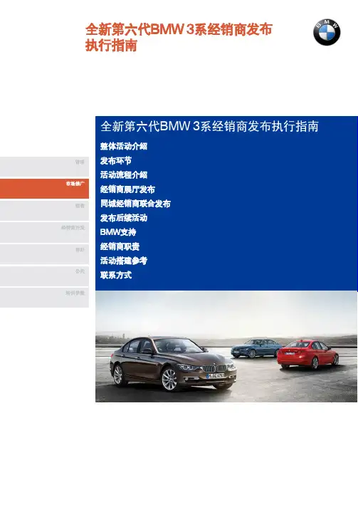
310W上市发布会经销商执行手册
- 格式:pptx
- 大小:3.39 MB
- 文档页数:32





新商盟(升级版)新商盟( 升级版) 系统零售户使用手册山东浪潮齐鲁软件产业股份有限公司2013年06月新商盟(升级版) 零售户使用手册目录1 综述...........................................................................................................................2....2 硬件配置说明............................................................................................................2...3 功能介绍....................................................................................................................3...3.1 系统主页......................................................................................................................3....3.1.1 登录系统.........................................................................................................3...3.1.2 系统主页.........................................................................................................3...3.2 卷烟订货......................................................................................................................4....3.2.1简述........................................................................................................................4....3.2.2流程图....................................................................................................................4....3.2.3下单订货操作.........................................................................................................5...3.2.3.1卷烟订货第一步...........................................................................................6..3.2.3.2卷烟订货第二步...........................................................................................7..3.2.3.3卷烟订货第三步...........................................................................................8..3.2.4辅助订货功能说明.................................................................................................8...3.2.4.1 我的收藏功能项说明................................................................................8..3.2.4.2 当前订单功能项说明................................................................................9..3.2.4.3 订单查询功能项说明..............................................................................1..03.3 我的社区....................................................................................................................1..0..3.4 留言板........................................................................................................................1..1..3.5 品牌展示区.................................................................................................................1..2.3.6 系统公告....................................................................................................................1..2..3.7 消息、帐号、退出系统.............................................................................................1..3.1 综述新商盟系统,是以零售户网上订购卷烟为主的电子商务平台,其中包括卷烟订货、我的社区、留言板、品牌展示、系统公告等功能,二期拓展品牌培育、智能推荐、事件营销、网上结算相应功能。
用户指导手册目录1 规则 / 规范 / 认可 (1)2 装置的描述 (3)2.1 物理原理 (4)2.2 装置概述 (8)2.3 对比:3RW3软起器与SIKOSTART 3RW22和SIKOSTART3RE34软起动器 (11)2.4 对比:3RW3软起动器与3RA星-三角组合起动器 (13)2.5 配置注解 (13)3 应用与使用 (15)3.1 应用领域和选用准则 (15)3.2 组装规范 (15)3.3 综述表:补偿系数 (18)3.3.1 独立式3RW30/31软起动器 (18)3.3.2 与3RV1断路器组合的3RW30/31软起动器 (19)3.3.3 3RT接触器与3RU1热过载继电器以及3RW3软起动器的组合 (21)3.3.4 3RT接触器与3RB10电子式过载继电器和3RW3软起动器的组合 (23)3.4 举例电路 (26)3.5 调试 (27)3.6 动作信息及故障诊断 (29)3.7 时间图 (30)4 附件 (31)5 组装和连接 (33)5.1 组装 (33)5.2 连接 (33)5.3 接线图 (34)6 外形尺寸图 (37)7 技术参数 (38)7.1 控制部分电子元器件的参数 (38)7.2 电源部分电子元器件参数 (39)7.3 安装海拔高度 (40)7.4 IEC参数 (41)7.5 NEMA参数 (42)7.6 短路保护和熔断器协调配合 (43)3RW3电子式软起动器1规则 / 规范 / 认可3RW3电子式软起动器已通过UL和CSA认可。
UL / CSA UL 508外壳防护等级DIN EN标准外形导轨DIN EN 50 022电子式软起动器IEC 60947 - 4 - 2冲击危险保护IEC 60947 - 1和DIN 40050EMC IEC 60801 - 4 - 2 (草案)一般分辨率DIN EN 602 69 - 1A1控制器和开关元件DIN EN 602 69 - 1A1Gost (苏联)按Gost标准通过认可CTic澳大利亚EMC合格标志(相当于CE标志)表1:标准与认证,3RW3“在使用中开断”3RW3软起动器可用作于“在使用中开断”的开关。
锐腾AS21 1.5T&2.0T 用户手册上汽集团目录1 前言 (1)1.1 用户手册介绍 (1)1.1.1 用户手册 (1)1.1.2 特别声明 (1)1.1.3 提示信息 (1)1.2 车辆识别信息 (2)1.2.1 车辆识别标识 (2)1.2.2 车辆标牌 (3)2 仪表和控制 (3)2.1 仪表和控制装置 (3)2.2 组合仪表 (4)2.2.1 转速表 (4)2.2.2 发动机冷却液温度表 (4)2.2.3 燃油表 (4)2.2.4 车速表 (4)2.3 信息中心 (5)2.3.1 数字时钟 (5)2.3.2 警告符号 (5)2.3.3 累计(Trip)1 (6)2.3.4 挡位显示 (6)2.3.5 总里程 (6)2.3.6 行车电脑A (6)2.3.6.1 有报警灯的警告信息 (6)2.3.6.2 无报警灯的警告信息 (8)2.3.6.3 行车电脑信息 (11)2.4 警告灯和指示灯 (13)2.5 灯光及开关 (17)2.5.1 主灯光开关 (17)2.5.2 组合仪表背光照明调节 (18)2.5.3 前照灯照明高度手动调节 (18)2.5.4 雾灯开关 (18)2.5.5 灯光拨杆开关 (19)2.5.6 危险警告灯 (20)2.6 刮水器和洗涤器 (20)2.6.1 前风窗刮水器操作 (20)2.6.2 智能雨刮 (21)2.6.3 后风窗刮水器操作 (21)2.7 转向系统 (22)2.7.1 转向管柱调整 (22)2.7.2 电动助力转向 (22)2.8 喇叭 (23)2.9 后视镜 (23)2.9.1.1 外后视镜镜面电动调整: (23)2.9.1.2 外后视镜加热 (24)2.9.1.3 外后视镜折叠 (24)2.9.2 内后视镜 (24)2.10 遮阳板 (25)2.11 车窗 (25)2.11.1 电动车窗控制开关 (25)2.11.2 车窗操纵 (26)2.12 天窗 (26)2.12.1 使用须知 (26)2.12.2 天窗操作 (26)2.13 内部照明 (28)2.13.1 前室内照明灯和阅读灯 (28)2.13.2 后室内照明灯 (28)2.14 电源插座 (28)2.14.1 前排电源插座 (29)2.14.2 行李箱电源插座 (29)2.15 储物装置 (30)2.15.1 使用须知 (30)2.15.2 手套箱 (30)2.15.3 储物盒 (30)2.15.4 驾驶员侧储物盒 (30)2.15.5 小杂物箱 (31)2.15.6 行李箱储物盒 (31)2.15.7 眼镜盒 (32)2.16 杯托 (32)2.16.1 中控台杯托 (32)2.16.2 后扶手和后杯托 (32)2.17 车顶行李架 (33)2.17.1 车顶最大允许载荷 (33)2.17.2 定期检查 (33)3 空调和娱乐系统 (33)3.1 通风 (33)3.1.1 空调滤清器 (34)3.1.2 出风口 (34)3.2 自动控制空调 (35)3.2.1 控制面板 (35)3.2.2 空调系统显示屏 (35)3.2.3 空气分配模式 (35)3.2.4 温度调节 (36)3.2.5 自动控制空调模式 (36)3.2.6 A/C开关 (36)3.2.7 风量调节 (36)3.2.8 除霜/雾 (36)3.2.10 循环模式 (37)3.2.11 系统开关 (37)3.3 娱乐播放机 (37)3.3.1 重要安全信息: (37)3.3.2 屏幕使用注意事项 (38)3.3.3 娱乐系统可播放文件格式 (38)3.3.3.1 音频支持 (38)3.3.3.2 视频支持 (38)3.3.3.3 文本/图片支持 (38)3.3.3.4 IPod/iPhone兼容性 (39)3.3.4 基本操作 (39)3.3.4.1 娱乐播放机控制面板 (39)3.3.4.2 系统主界面 (40)3.3.4.3 功能块移动 (40)3.3.4.4 开机和关机 (40)3.3.4.5 方向盘控制键 (41)3.3.4.6 AV盒 (42)3.3.4.7 泊车模式音频策略 (42)3.3.4.8 音量调节 (42)3.3.4.9 插入和拔出USB存储设备 (42)3.3.4.10 连接和断开iPod (43)3.3.5 蓝牙电话 (43)3.3.5.1 使用须知 (43)3.3.5.2 蓝牙匹配及连接 (43)3.3.5.3 与手机配对 (44)3.3.5.4 从手机端配对 (44)3.3.5.5 电话菜单 (44)3.3.5.6 拨号键盘 (45)3.3.5.7 最近通话 (46)3.3.5.8 通讯录 (46)3.3.5.9 拨打电话 (47)3.3.5.10 同步电话簿 (48)3.3.5.11 快速检索 (48)3.3.5.12 列表拨打 (48)3.3.5.13 手机拨号 (49)3.3.5.14 其它功能 (49)3.3.5.14 来电 (49)3.3.6 娱乐 (50)3.3.6.1 使用须知 (50)3.3.6.2 收音机 (51)3.3.6.3 搜索电台 (52)3.3.6.4 播放音频文件 (53)3.3.6.4.1 最爱歌曲列表 (53)3.3.6.4.2 U盘文件夹列表 (55)3.3.6.5.1 AUX播放 (56)3.3.6.5.1 浏览图片 (57)3.3.7 空调 (57)3.3.8 车机互联(MirrorLink) (57)3.3.9 车辆设置 (58)3.3.9.1 车锁控制 (58)3.3.9.2 灯光控制 (58)3.3.10 设置 (59)3.3.10.1 蓝牙设置 (59)3.3.10.2 显示设置 (59)3.3.10.3 音效设置 (60)3.3.10.4 时间日期设置 (61)3.3.10.5 系统设置 (62)4 座椅和保护装置 (62)4.1 座椅 (62)4.1.1 概述 (62)4.1.2 头枕 (62)4.1.3 手动座椅调节 (63)4.1.4 电动座椅调节 (64)4.1.5 前座椅加热功能 (64)4.1.5 后座椅 (65)4.1.5.1 后座椅靠背调节 (65)4.1.5.2 后座椅折叠 (65)4.1.5.3 后座椅靠背展开并锁止 (65)4.2 安全带 (65)4.2.1 安全带的保护作用 (66)4.2.2 如何正确佩戴安全带 (66)4.2.2.1 胯-肩式安全带 (67)4.2.2.2 安全带正确走向 (68)4.2.2.3 安全带上固定点高度调节 (68)4.2.2.4 怀孕期间使用安全带 (69)4.2.2.5 伤残人士使用安全带 (69)4.2.3 儿童如何使用安全带 (69)4.2.3.1 婴幼儿 (69)4.2.3.2 较大的儿童 (70)4.2.4 安全带预张紧器 (70)4.2.5 安全带的检查、保养和更换 (71)4.2.5.1 检查安全带 (71)4.2.5.2 保养安全带 (71)4.2.5.3 更换安全带 (72)4.3 安全气囊 (72)4.3.1 概述 (72)4.3.3 安全气囊不展开的条件 (75)4.3.3.1 正面安全气囊 (75)4.3.3.2 侧面安全气囊 (76)4.3.4 车辆安全气囊的维修和更换 (77)4.3.4.1 维修安全气囊 (77)4.3.4.2 发生碰撞事故后更换安全气囊系统零部件 (77)4.3.5 车辆安全气囊的处置 (78)4.4 儿童保护装置 (78)4.4.1 重要安全说明 (78)4.4.1.1 关于使用儿童座椅的重要安全说明 (78)4.4.1.2 关于儿童乘车安全和侧面安全气囊的重要说明 (78)4.4.2 儿童座椅组别 (79)4.4.2.1 儿童座椅组别 (79)4.4.2.2 组0/0+儿童座椅 (80)4.4.2.3 组1儿童座椅 (81)4.4.2.4 组2儿童座椅 (81)4.4.2.5 组3儿童座椅 (81)4.4.3 儿童座椅固定方式 (82)4.4.3.1 用车辆的胯-肩式安全带固定 (82)4.4.3.2 用车辆的ISOFIX装置固定 (82)5 起动和驾驶 (83)5.1 钥匙 (83)5.1.1 概述 (83)5.1.2 更换遥控钥匙电池 (84)5.2 儿童保护锁 (84)5.3 防盗系统 (85)5.3.1 发动机防盗系统 (85)5.3.2 电子防盗报警系统 (85)5.3.2.1 锁止和解锁 (85)5.3.2.2 遥控门锁系统的操作(无钥匙起动) (85)5.3.2.3 无钥匙锁止 (85)5.3.2.4 无钥匙解锁 (86)5.3.2.6 误锁 (86)5.3.2.7 防盗报警指示灯 (86)5.3.2.8 防盗报警声音 (86)5.3.2.9 内部锁开关 (87)5.3.2.10 车门内拉手 (87)5.3.2.11 行车落锁 (87)5.3.2.12 自动解锁 (87)5.3.3 尾门 (87)5.4 起动和关闭发动机 (88)5.4.1 点火开关(无钥匙起动) (88)5.4.3 起动发动机(无钥匙起动) (89)5.4.3.1 起动程序 (89)5.4.3.2 车辆备用起动程序 (90)5.4.4 关闭发动机 (90)5.5 经济环保的驾驶方式 (90)5.5.1 磨合 (90)5.5.2 环境保护 (91)5.5.3 经济性驾驶 (91)5.5.4 特殊环境中的驾驶 (91)5.5.4.1 雨雪天气中驾驶 (91)5.5.4.2 积水路面上驾驶 (91)5.5.5 检查和保养 (92)5.6 催化转换器 (92)5.7 燃油系统 (93)5.7.1 燃油要求 (93)5.7.2 加油口 (93)5.7.2.1 燃油加油口小门 (93)5.7.2.1 油箱加油口盖 (93)5.7.3 燃油加注 (93)5.7.4 燃油系统积碳清洗剂 (93)5.8 双离合自动变速器(TST)* (94)5.8.1 使用须知 (94)5.8.2 换挡 (94)5.8.2.1 换挡杆操作 (94)5.8.2.2 换挡杆位置 (95)5.8.2.3 换挡速度 (95)5.8.2.4 强制降挡(Kick-down) (95)5.8.3 车辆起步 (95)5.8.4 坡道行驶 (95)5.8.4.1 上坡起步 (95)5.8.4.2 下坡行驶 (96)5.8.5 控制模式 (96)5.8.5.1 经济模式 (96)5.8.5.2 运动模式 (96)5.8.5.3 雪地模式 (96)5.8.5.4 巡航控制模式 (96)5.8.5.5 Tiptronic模式 (97)5.8.6保护模式 (97)5.8.6.1 双离合自动变速器过热保护 (97)5.8.6.2 跛行模式 (97)5.8.6.3 严重功能性故障 (98)5.9 制动系统 (98)5.9.1 行车制动器 (98)5.9.1.1 真空助力系统 (98)5.9.1.3 电子制动力分配系统(EBD) (98)5.9.1.4 电子制动辅助系统(EBA) (98)5.9.1.5 坡道起步辅助系统(HHC) (99)5.9.1.6 自动驻车(Auto Hold) (99)5.9.2 防抱死制动系统(ABS) (100)5.9.2.1 紧急状态下的制动 (101)5.9.2.2 ABS故障警告灯 (101)5.9.3 一键式电子驻车系统(EPB) (101)5.9.3.1 启用电子驻车系统 (101)5.9.3.2 关闭电子驻车系统 (102)5.9.3.3 辅助起步功能 (102)5.9.3.4 紧急制动功能 (102)5.10 动态稳定控制系统和牵引力控制系统 * (102)5.10.1 动态稳定控制系统(SCS) (102)5.10.2 牵引力控制系统(TCS) (102)5.10.3 开启与关闭 (103)5.10.4 动态稳定控制/牵引力控制警告灯 (103)5.11 Start-Stop智能启停节油系统 (103)5.11.1 发动机自动停机 (104)5.11.2 发动机自动起动 (104)5.11.3 蓄电池 (105)5.11.4 Start-Stop智能启停节油系统故障 (105)5.11.5 蓄电池严重亏电,起动机不工作 (105)5.12 巡航控制系统 (105)5.12.1 巡航控制系统激活 (106)5.12.2 巡航目标车速调节 (106)5.12.3 暂停 (106)5.12.4 恢复 (107)5.13 泊车辅助系统 (107)5.13.1 超声波传感器泊车辅助系统 (107)5.13.1.1 后部泊车辅助系统 (107)5.13.1.2 泊车辅助系统工作状态 (107)5.13.1.3 泊车辅助系统的报警周期 (108)5.13.2 泊车摄像头系统 (108)5.13.3 泊车辅助信息 (108)5.14 装载 (109)5.14.1 行李箱装载 (109)5.14.2 车内装载 (109)6 行驶途中故障 (110)6.1 危险警告装置 (110)6.1.1 危险警告灯 (110)6.1.2 三角警示牌 (110)6.2 跨接起动 (110)6.2.1 跨接电缆 (111)6.3.1.1 牵引钩 (112)6.3.1.2 牵引 (112)6.3.2 托运车辆 (113)6.4 轮胎修补与车轮更换 (114)6.4.1 备胎和工具箱 (114)6.4.2 更换备胎工具 (114)6.4.3 更换车轮 (114)6.4.4 放置千斤顶 (114)6.4.5 换上备胎 (115)6.4.6 紧凑型备胎 (116)6.5 更换保险丝 (116)6.5.1 保险丝 (116)6.5.1.1 保险丝熔断前后对比 (116)6.5.1.2 保险丝盒 (117)6.5.2 蓄电池保险丝盒 (117)6.5.3 乘客舱保险丝盒 (118)6.5.4 发动机舱保险丝盒 (119)6.6 更换灯泡 (121)6.6.1 灯泡规格 (121)6.6.2 更换操作 (122)6.6.2.1 前室内照明灯和阅读灯 (122)6.6.2.2 后室内照明灯 (122)6.6.2.3 手套箱灯和行李箱灯 (123)7 维修和保养 (123)7.1 维护保养 (123)7.1.1 保养 (123)7.1.2 保养记录 (123)7.1.3 更换制动液 (123)7.1.4 更换冷却液 (123)7.1.5 废气排放控制 (124)7.1.6 车主的维护保养 (124)7.1.7 特殊状态 (124)7.1.8 车库中的安全 (124)7.1.9 有毒液体 (125)7.2 发动机盖 (125)7.2.1 打开发动机盖 (125)7.2.2 关闭发动机盖 (125)7.2.3 发动机盖未关报警 (125)7.3 发动机舱 (126)7.4 发动机 (126)7.4.1 发动机机油的ACEA分类 (126)7.4.2 检查和添加机油 (127)7.5.2 维护和保养 (128)7.6 冷却系统 (129)7.6.1 检查和添加冷却液 (129)7.6.2 冷却液规格 (130)7.6.3 防冻液 (130)7.7 制动 (130)7.7.1 制动衬块 (130)7.7.2 检查和添加制动液 (131)7.7.3 制动液规格 (131)7.8 蓄电池 (131)7.8.1 蓄电池维护 (131)7.8.2 蓄电池更换 (132)7.9 洗涤器 (132)7.9.1 检查和加注洗涤液 (132)7.9.2 洗涤器喷嘴 (133)7.9.3 洗涤液规格 (133)7.10 刮水器 (133)7.10.1 刮水片 (133)7.10.2 更换风窗玻璃刮水片 (134)7.11 轮胎 (134)7.11.1 概述 (134)7.11.1.1 新轮胎 (134)7.11.1.2 标有方向性胎面花纹的轮胎 (134)7.11.1.3 轮胎的使用寿命 (135)7.11.2 轮胎的检查 (135)7.11.2.1 轮胎气压 (135)7.11.2.2 气门 (135)7.11.2.3 刺破的轮胎 (135)7.11.3 轮胎磨损标记 (135)7.11.4 更换轮胎 (136)7.11.5 车轮换位 (136)7.12 清洁和车辆保养 (137)7.12.1 汽车外部养护 (137)7.12.1.1 洗车 (137)7.12.1.2 上蜡 (138)7.12.1.3 抛光油漆 (138)7.12.1.4 刮水片 (139)7.12.1.5 车窗和镜子 (139)7.12.1.6 塑料部件 (139)7.12.1.7 油漆损伤 (139)7.12.1.8 密封条 (139)7.12.1.9 车轮 (139)7.12.2 汽车内部养护 (140)7.12.2.1 塑料部件、人造革和织物 (140)7.12.2.2 安全气囊的罩盖 (140)7.12.2.3 座椅安全带 (140)7.12.2.4 地毯和织物 (140)7.12.2.5 皮革 (140)7.12.2.6 组合仪表、娱乐显示器 (140)8 技术数据 (141)8.1 车辆主要尺寸参数 (141)8.2 整车质量参数 (141)8.3 发动机主要参数 (142)8.4 动力性能参数 (143)8.5 推荐的油液和容量 (143)8.6 四轮定位参数表(空载) (144)8.7 车轮和轮胎 (144)8.8 备胎 * (144)8.9 轮胎气压(冷态) (144)1 前言1.1 用户手册介绍1.1.1 用户手册感谢您购买上汽集团的产品。
ContentsDescription Page Section 1: General Information . . . . . . . . . . . . . .2Section 2 . Trip Unit Installation . . . . . . . . . . . . . . .2Section 3 . Trip Unit Controls and Functions . . . . .5Section 4 . Neutral Current Sensor Information . . .7Section 5 . 100% Rated LD and MDL FrameCircuit Breakers . . . . . . . . . . . . . . . . . .7Instruction Leaflet for theLES/MES 310+ Electronic Trip Unit2Instruction Leaflet IL012043ENEffective January 2016Instruction Leaflet for theLES/MES 310+ Electronic T rip UnitEATON WARNINGDO NOT ATTEMPT TO INSTALL OR PERFORM MAINTENANCE ON EQUIP-MENT WHILE IT IS ENERGIZED. DEATH OR SEVERE PERSONAL INJURY CAN RESULT FROM CONTACT WITH ENERGIZED EQUIPMENT. ALWAYS VERIFY THAT NO VOLTAGE IS PRESENT BEFORE PROCEEDING.Section 1: General InformationT able 1. Parts ListL OR M 310+ ELECTRONIC TRIP UNIT IL FOR 310+ ELECTRONIC TRIP UNITSNEUTRAL CURRENT SENSOR (GROUND FAULT ONLY)NEUTRAL & ALARM LEADS (GROUND FAULT ONLY)4TH POLE CT ASSEMBLY (4 POLE ONLY)Section 2. Trip Unit InstallationStep 1Remove the 8 screws (10 for MDL -frame) holding the base and cover together (Figure 1) .Figure 1. LES Base-cover Screws.Step 2Remove the 2 retaining screws (3 for 4-pole breaker) from the shunt plate inserts in the base of the circuit breaker frame .Step 3 (4-pole Only)Plug the current sensor secondary winding connector into the recep-tacle in the side of the trip unit . Either polarity is acceptable since the secondary winding connector is not polarized .Figure 2. 4th Pole Installation.Step 4Position the retaining screws in the trip unit and current sensor con-ductor holes (Figure 3) .Figure 3. Retaining Screws Location in Trip Unit.Trip UnitSecondary Winding ConnectorCurrentSensor3Instruction Leaflet IL012043ENEffective January 2016Instruction Leaflet for theLES/MES 310+ Electronic T rip Unit EATON Figure 5. Wire Routing Cable Tie Placement.Cable TiesBreaker Frame Wiring HarnessesFigure 7. LES 4-pole T rip Unit Mounting Screw Locations.Load EndTest Port4Instruction Leaflet IL012043ENEffective January 2016Instruction Leaflet for theLES/MES 310+ Electronic T rip UnitEATON Step 7 (MES Trip Units)Starting with the center pole (mech pole), torque line side screws to 10-12 lb .-ft . (14-16 N·m) and load side screws to 6 – 8 lb .-ft . (8 – 10 N·m) (Figure 8) .Figure 8. MES T rip Unit Mounting Screw Locations.Step 8.Install any accessories, if required, using the appropriate instruction leaflet .The following types of internal accessories, which mount on the trip unit, are available for use . The number of the IL covering the installa-tion of each accessory is shown .• Alarm (Signal)/Lockout (ASL) Switch . . . . . . . . . . . . . . . . . . . . . . . . . . . . . .I .L . 29C183• Auxiliary Switch . . . . . . . . . . . . . . . . . . . . . . . . . . . . . . . . . . . . . . . . . . . . . . . . . . . . . . . . . . . . . .I .L . 29C123• Shunt Trip . . . . . . . . . . . . . . . . . . . . . . . . . . . . . . . . . . . . . . . . . . . . . . . . . . . . . . . . . . . . . . . . . . . . . . . .I .L . 29C146• Low Energy Shunt Trip . . . . . . . . . . . . . . . . . . . . . . . . . . . . . . . . . . . . . . . . . . . . . . . . . . .I .L . 29C147•Undervoltage Release Mechanism (Handle Reset) . . . . . . .I .L . 29C170Trip Unit Wire Routings with Accessories:•Alarm (Signal)/Lockout (ASL) Switch and Auxiliary Switch:From trip unit, route wiring harnesses through the recessed cen-ter portion of the accessory bracket and through the slots in the breaker frame .•Shunt Trip:From trip unit, route wiring harnesses through the recessed cen-ter portion of the accessory bracket overlapping the white and yellow accessory wires, over the shunt trip, and through the slots in the breaker frame .•Low Energy Shunt Trip and Undervoltage Release Mechanism (Handle Reset):From trip unit, route wiring harnesses under accessory bracket and through the slots in the breaker frame .Step 9Finish the installation by installing the cover on the base, as shown in Figure 10 .Figure 9. Re-attach Cover and Base of the Breaker.5Instruction Leaflet IL012043ENEffective January 2016Instruction Leaflet for theLES/MES 310+ Electronic T rip Unit EATON Figure 11. LSIG Short Delay and Ground Fault Time Settings.1 . Test Port - A test port is built into each trip unit to allow use of afunctional test kit . The test kit performs a test of the Long Delay, Short Delay and Ground Fault functions (Plug-In Test Kit Catalog #MTST230V) . Remove the test port cover prior to connecting to the test port .2 . Test/Alarm LED - A dual function, bi-color (red-amber) LED . It isused as an amber no trip indicator when using the test port . In normal modes, the red LED indicates a high load alarm . For a high load alarm, it will blink ON-OFF if the continuous current is 105% of the I r setting and is present for a duration over 38 sec-onds .3 . I r - Continuous current setting . In accordance with standardsrequirements, the trip unit initiates a trip of the circuit breaker within 2 hours for an overload of 135% and will trip as a function of l²t for higher currents . Continuous current values for each let-tered setting are indicated by the chart displayed on the left side of the trip unit label .4 . t r - The number of seconds required to trip @ 6x I r . For example,if I r = 250A, t r = 2 sec, and load current = 1500A, or 6x I r , then the breaker will trip in 2 seconds .5 . l sd - Setting in multiples of l r for short circuit conditions thatexceed the short delay pick-up setting, the trip unit initiates a trip after a predetermined delay .otee:N In addition to the short delay trip function, there is a fixed instan-taneous override for the 600A and 800A trip units . The override for the 600A is fixed at 5620A, the override for the 800A is fixed at 6800A . If a fault current exceeds these override values, the breaker will trip instanta-neously (in 20 milliseconds or less) .6 . I g - Ground fault pick-up setting . It is used on the LSIG and LSGstyles to set the ground fault pick-up as a percentage of I n (frame current) . For example, a 600A frame with an I g setting of 0 .4 will provide a ground fault pick-up at 240A .7 . t sd - for the LSI style, the short delay time is a flat responsedetermined by the tsd switch settings of INST 120ms, or 300ms . For the LS styles, the short delay time is an I²t function, with a delay of 67ms at a Isd setting of 6x .8 . t sd / t g - For the LSIG style, the short delay is a flat responsedetermined by the tsd/tg switch settings of INST 120ms or 300ms . This switch is a dual switch that also determines the ground fault time settings of INST , 120ms or 300ms . For exam-ple, if the t sd /t g switch is set at position J, then both short delay time and ground fault time are at INST flat . As another example, set the t sd /t g switch at position L; the short delay time is INST and the ground fault time is 300ms . The LSIG label (Figure 11) should be used in conjunction with the t sd /t g switch to set any one of nine possible combinations of short delay and ground fault times .9 . t g - For the LSG style, the short delay time is an I²t functionwhile the ground fault flat time is set by the t g switch .10 . Status LED - A green status light indicates the operational statusof the trip unit . If the load current exceeds approximately 20% of the maximum current rating (I n ) of the breaker, the status lightSection 3. Trip Unit Controls and FunctionsA . Trip unit controls and settings (refer to Figures 10 and 11) .Figure 10. LES / MES T rip Units Settings.I r Settings LESMESA = 250AA = 320AB = 300A B = 400AC = 315A C = 450AD = 350A D = 500AE = 400A E = 600AF = 450AF = 630AG = 500A G = 700AH = 600A = InH = 800A = In*Settings t g (ms)Inst.120300t sd(ms)Inst.J K L 120M n O 300PQR6Instruction Leaflet IL012043ENEffective January 2016Instruction Leaflet for theLES/MES 310+ Electronic T rip UnitEATON will blink on for one second and off for one second .B . Other features and options of the LES/MES 310+ trip units .1 . The High Load Alarm Relay option will provide a SPST contactclosure when the trip unit current equals or is greater than 105% of In for a period of 38 seconds . If the current drops below the 105% value, the contact will open . The yellow and green wires that exit the right side of the breaker are the common (C) and normally open (NO) of this relay (See Figure 12) .2 . The Ground Fault Alarm Only option operates in a similar fash-ion as the High Load Alarm . The SPST contact will close if the ground fault pick-up setting is exceeded and will open when below the ground fault pick-up setting . The yellow and green wires that exit the right side of the breaker are the common (C) and normally open (NO) of this relay (See Figure 12) .3 . The Ground Fault Relay option will provide a SPST contact clo-sure immediately before the breaker will trip on a ground fault over current detect . This closure is momentary (50ms) and the customer must provide the necessary external circuitry in order to latch this signal . The yellow and green wires that exit the right side of the breaker are the common (C) and normally open (NO) of this relay (See Figure 12) .otee:N The High Load Alarm Relay can be selected with LS, LSI LSG, and LSIG trip units . For the LSG and LSIG trip units, the High Load Alarm will function normally . However, if the breaker trips due to a ground fault con-dition, the relay will respond with a ground fault alarm as indicated above .The Ground Fault Alarm Only can be selected for LSG and LSIG trip units only . This selection has precedence over all other relay functions . When the Ground Fault Alarm Only is selected, the High Load Alarm Relay feature is not available .otee:N The contact ratings of the relay are: 2A at 30 VDC and 0 .5 A at 125 VAC .4 . The Zone Selective Interlock (ZSI) option provides a wired meth-od of coordinating Upstream and Downstream breakers . The coordinating signals are provided by the White\Red stripe (Z in ), White\Black stripe (Z out ), and Black (common ground) wires that exit the right side of the breaker . ZSI may be ordered on LSI and LSIG trip units .Zone Selective Interlocking is active for the short delay and the ground fault delay tripping functions . The LES/MES 310+ Trip Unit Zone Selective Interlocking feature is compatible with OPTIM and Digitrip Trip Units, including all other 310+ models on Series G: (RG, NG LG, JG) and Series C (FD and KD) breakers .Three wires exit the breaker with the following color code and function: White/Black Stripe=Zone Out, White/Red Stripe=Zone In, and Black=Common (See Figure 12) .A typical connection for a two breaker system is accomplished by connecting the Z out wire of the downstream breaker to the Z in of the upstream breaker . The common black wires of both break-ers must also be connected .If a high current fault is sensed from the load on the down-stream breaker, both breakers will sense the fault . However, the downstream breaker will send the interlock signal to the upstream breaker informing it not to trip . This delay allows the downstream breaker to clear the fault without the upstream breaker tripping .However, if for some reason the downstream breaker does not clear the fault in the set delay time, the upstream breaker will then clear the fault at or before its defined t sd or t g .Multiple breakers may be connected in a system to create a zone of protection . For faults outside the zone of protection, the trip unit of the circuit breaker nearest the fault sends an inter-locking signal (Z out ) to the trip unit of the up-stream circuit break-er . (Z in ) This interlocking signal restrains immediate tripping of the upstream circuit breaker until its programmed coordination time is reached . Thus zone selective interlocking applied correctly can reduce damage due to circuit or ground fault conditions . A table of the settings of the two breakers with the respective outcomes (Both Trip or Downstream (Dn) Trips) of the breakers is indicated below for the conditions mentioned in the table head-ing .UpstreamINST120ms 300ms D o w n s t r e a mINST Both Dn 43ms Dn 43ms 120ms Both Dn 52ms Dn 52ms 300msBothDn 43msDn 43msotee:N A single breaker with the Zone Selective Interlocking feature enabled will not trip at the programmed time settings, unless Self Interlocked . That is, the Z out wire should be connected to the Z in wire .5 . Remote Maintenance Mode (RMM) is an option that allows auser to remotely lower the instantaneous pickup of the breaker to 2 .5x the frame rating (I n ), and to bypass any programmed delays (t sd or t g ) . The purpose of the function is to to reduce inci-dent energy during a fault condition . For example, a 600A (I n ) LD breaker with the switch set to 2 .5x would trip instantaneously when the current exceeded 1500 A .The RMM is enabled by applying 24VDC to the two wire cable that exits the left side of the breaker . The wires are color coded Y ellow (+24V) and Black (common ground) - see Figure 14 . A blue colored LED on the trip unit lights when the breaker is in RMM (Figure 13) .The lighted blue LED indicates that RMM is enabled . This setting corresponds to 2 .5x of I n . Turning the I sd switch on the trip unit has no effect on either the Maintenance Mode or the t sd \t g set-tings while the blue LED is lit .Also, a relay contact closure indicates that the RMM has been enabled . The blue and red wires are the C and NO contacts of this relay . The relay has a dual function: 1) enable RMM and 2) provide a contact closure indication that RMM is enabled .Both the yellow and black set of wires and the red and blue set of wires exit on the left side of the breaker .otee:N The RMM contacts are rated at 2A at 30 VDC and 0 .5A at 125 VAC .7Instruction Leaflet IL012043ENEffective January 2016Instruction Leaflet for theLES/MES 310+ Electronic T rip Unit EATON Figure 12. Alarm, ZSI, and Neutral Wiring Diagram.GRN YELBLKWHI/BLK STRIPEN.C.WHI/RED STRIPEGRYWHIALARM ZSIRELAYCABLENEUTRAL12D7NRD40041+10-3W12NC14NO18W29NC27NO2K2CONT 2A 24VDC TQ2SA-24VJ7-38-POS "PHD" RAJ7-1J7-5J7-7J7-8J7-2J7-6J7-4ZOUTZINSection 4. Neutral Current Sensor Informa-tion.Ground fault trip units are supplied from the factory with pigtail lead connections for a neutral current sensor (white and grey wires) . A neutral current sensor shown in Figure 14 is available . 310+ Ground Fault Trip Units detect ground fault currents through Residual Sensing . They are not designed to use source ground or zero sequence ground fault sensing methods . If the system neutral is grounded, but no phase to neutral loads are used, the neutral cur-rent sensor is not necessary . In that case, the white and grey leads on the trip should be cut off before installation . If the system neutral is grounded and phase to neutral loads are used, then the neutral current sensor must be used . It should be connected to the breaker according to Figure 15 It has the same turns ratio as the phase cur-rent sensors in the trip unit .NOTICETHE POLARITY OF THE SENSOR CONNECTIONS IS CRITICAL. ALWAYS OBSERVE THE POLARITY MARKINGS ON THE INSTALLATION DRAW-INGS. THE POLARITY MARKINGS ARE IDENTIFIED AS WHITE DOTS ON THE TRANSFORMERS. TO INSURE CORRECT GROUND FAULT EQUIPMENT PERFORMANCE, CONDUCT FIELD TESTS TO COMPLY WITH NATIONAL ELECTRIC CODE REQUIREMENTS UNDER ARTICLE 230-95-C.otee:N See wiring instructions below for special restrictions on accessory wir-ing for ground fault breakers . Then install the ground fault alarm and neutral current sensor connector printed circuit board as described previously .CAUTIONLEADS COULD BE DAMAGED IF IN CONTACT WITH MOVING PARTS. ACCESSORY WIRES SHOULD BE FORMED AND ROUTED TO CLEAR ALL MOVING PARTS.Leads to be routed:1 .2 leads (white and grey) for the neutral current sensor .2 . 2 leads (yellow and green) for the ground fault alarm relay It is not possible to have leads exiting the breaker on the opposite side . For rear exiting leads, thread the leads through the wiring troughs/tunnels in the side of the circuit breaker case . For side exiting leads, use the slots in the side of the case . Use the center trough or slot for the neutral current sensor leads (white and grey) and the trough or slot closest to the trip unit for the alarm leads (yel-low and green) .Any other leads to be brought out should then be threaded through the wiring trough closest to the trip unit .Section 5. 100% Rated LD and MDL Frame Circuit BreakersCLD, CHLD, CLDC, CMDL, and CHMDL circuit breakers are suitable for continuous operation at 100% of the frame rating if used with CU only 90° C insulated wire and AL9CU terminals in an enclosure which measures at least 24” high x 15” wide x 6” deep for the LD and 42" high x 18" wide x 7 .5" deep for the MDL . Ventilation is not required in an enclosure having these minimum dimensions .EatonElectrical Sector1000 Eaton Boulevard Cleveland, OH 44122United States877-ETN-CARE (877-386-2273) © 2016 EatonAll Rights ReservedPrinted in USAPublication No. IL012043EN / TBG001166 Part Number: IL012043ENH03 January 2016Eaton is a registered trademark.All other trademarks are property of their respective owners.Instruction Leaflet IL012043EN Effective January 2016Instruction Leaflet for the LES/MES 310+ Electronic T rip UnitFigure 15. Neutral and Alarm Wiring Diagram.The information, recommendations, descriptions, and safety nota-tions in this document are based on Eaton’s experience and judg-ment with respect to Retrofitting of Power Breakers . This instruction-al literature is published solely for information purposes and should not be considered all-inclusive . If further information is required, you should consult an authorized Eaton sales representative .The sale of the product shown in this literature is subject to the terms and conditions outlined in appropriate Eaton selling policies or other contractual agreement between the parties . This literature is not intended to and does not enlarge or add to any such contract . The sole source governing the rights and remedies of any purchaser of this equipment is the contract between the purchaser and Eaton . NO WARRANTIES, EXPRESSED OR IMPLIED, INCLUDING WARRANTIES OF FITNESS FOR A PARTICULAR PURPOSE OR MERCHANTABILITY, OR WARRANTIES ARISING FROM COURSE OF DEALING OR USAGE OF TRADE, ARE MADE REGARDING THE INFORMATION, RECOMMENDATIONS, AND DESCRIPTIONS CONTAINED HEREIN. In no event will Eaton be responsible to the purchaser or user in contract, in tort (including negligence), strict liability or otherwise for any special, indirect, incidental or conse-quential damage or loss whatsoever, including but not limited to damage or loss of use of equipment, plant or power system, costof capital, loss of power, additional expenses in the use of existing power facilities, or claims against the purchaser or user by its cus-tomers resulting from the use of the information, recommendations and description contained herein .。


WE310F5-I/P Evaluation Board Quick Start Guide1VV0301671 Rev.13Page 1 of 22023-05-07.. Copyright © 2023 Telit Cinterion. All rights reserved.UART0UART1WE310F5-I/P Evaluation BoardQuick Start GuideThis Quick Start Guide will walk you through the basic setup required to run the Serial-to-Wireless application.The WE310F5 module evaluation board is available in two variants: • WE310F5-I includes an antenna• WE310F5-P includes only the RF PAD and requires an external antenna.Figure 1: WE310F5-I EVBThe external antenna variant WE310F5-P EVB has the RF connector as shown in the figure below:Figure 2: WE310F5-P EVBKit Contents• WE310F5 EVB Quick Start Guide (this document) • WE310F5 Evaluation Board • 1 Micro-USB Cable•Antenna in case the “WE310F5-P” modulePrerequisites• Install Tera TermNote: The ports required for Program and Run mode: • UART0 Port: Run Mode• UART1 Port: Programming Mode1Program the WE310F5 Module1. Connect a Micro USB cable, one end to your PC/Laptop and the other to the WE310F5 EVB's UART1 Port (Evaluation board).2. Toggle the PROGRAM/RUN switch to PROGRAM .3. Download and unzip the latest firmware package from the Telit Download Zone (WE310>WE310F5>Firmware Release & Release Note ).4. Navigate to the\Downloads\Telit_WE310_M_39.00.00x\documents\Telit_Wifi_Image_Tool.zip file and launch the T elit_Wifi_Image_Tool.exeapplication.5. Select the appropriate COM Port and click Browse to navigate to the s2w.bin file in the downloaded package.6. To initiate flash, select Load default file system and then click Program .7. Once the flash process is complete, click OK . The WE310F5 EVB is now ready to configure.ON/OFFPROGRAM/RUN UART1UART0ON/OFFPROGRAM/RUNWE310F5-I/P Evaluation Board Quick Start Guide1VV0301671 Rev.13Page 2 of 22023-05-07.. Copyright © 2023 Telit Cinterion. All rights reserved.2 R un the WE310F5 Module1. Disconnect and reconnect the micro-USB cable from UART1 to the UART0 port.2. Change the toggle switch position to RUN .3. To power the board, toggle the ON/OFF switch to the ON position .4. Now, launch the Tera term application that you have installed on your laptop.5. Go to File->New Connection .6. Select the Appropriate COM Port and click OK .7. Go to Settings->Serial Port , s et the Baud Rate as 115200, and click OK . The WE310F5 EVB is now ready for use.3 W iFi OperationsThe following use cases describe the WiFi operations of theWE310F5 module. The WE310F5 module supports two modes of operations:• Station Mode • Limited AP ModeStation ModeTo configure the module in Station Mode, configure an Access Point with an Open/Secured Network. In this case, the configuration is a secure network. 1. To start the WLAN Interface AT+WNI=02. To connect to a networkAT+WNCN=1,"test","demo@123"Limited AP ModeTo configure the WE310F5 In LAP Mode: 1. To set the module in AP Mode AT+WNI=12. To set the Static IPAT+WNIPC=0,1,192.168.230.3,255.255.255.0,192.168.230.1 3. To set the DHCP server IPAT+WNAPIPC=0,192.168.230.2,192.168.230.10,864000004. To create a NetworkAT+WNCR=0,"TELIT",6,"WPA2-PSK","AES","1234567890"4Bluetooth®OperationsWE310F5 module supports the Bluetooth ® Low Energy 5.0 version.TIO CommunicationTo initiate the Bluetooth ® Low Energy interface via TIO communication, use the following AT commands: AT+BI=1 AT+BIOCAP=0 AT+BTIO=1 AT+BADVE=0 AT+BOADGATT CommunicationTo initiate the Bluetooth ® Low Energy interface via GATT Communication, use the following AT commands: AT+BI=1AT+BATTRIB="pserv","uuid=12AA"AT+BATTRIB="char","prop=0x1A","uuid=12A1"AT+BATTRIB="charval","perm=0011","len=1","val=0x59"AT+BATTRIB="COMPLETE" AT+BADVE=1 AT+BOADResource LinksFor the latest Firmware Packages and product documentationdownloads:https:///we310f5-download-zoneContact Information, SupportFor technical support and general questions please e-mail: • ****************Alternatively, use:https:///contact-us。