美国伊顿MN03902008E-英文
- 格式:pdf
- 大小:1.45 MB
- 文档页数:92

23% more energy efficient than the next leading brandBussmann series Fusetron fuses provide advanced protection time-delay fuse. Product description: Eaton’s Bussmann™ series Fusetron™fuses are, on average, 23% more energy efficient than the next leading brand, savingusers money*. The energy efficient RK5 fuses utilize a separate overload element to provide the best time-delay performance for sizing as close as 125% of motor Full Load Amps (FLA). Fusetron, 225-600 amp fuses enhance safety with insulated end caps to reduce exposure to live parts and extend air gap distance between blades of adjacent mounted fuse or to housing.Features and benefits:• Dual-element featureprovides the besttime-delay performance,allowing closer sizingand superior protectionof motors andtransformers.• Closer sizing allows forsmaller fuses and lesscostly switches.• 200kA interrupting ratingallows use in a broadrange of applications.• Most common fusesare in stock and readyto ship within 24 hourswith QuikShip EverydayService.Time-delay Fusetron fuses are ideallysuited for protecting motor andtransformer loads.* T est results are based on weightedsales volume of Fusetron andFerraz Shawmut (Mersen) fuses byselected amp and volt ratingcombination. Next leading brandrefers to Ferraz Shawmut basedon third-party fuse market sharedata for a twenty-seven monthperiod (July 2008 throughSeptember 2010).SERIESFusetron™ advanced protection time-delay fusesEaton, Bussmann, Fuses Made Simple, Fusetron, Limitron and Low-Peak are valuable trademarks of Eaton in the US and other countries. You are not permitted to use the Eaton trademarks without prior written consent of Eaton.CSA is a registered trademark of the Canadian Standards Group.UL is a registered trademark of the Underwriters Laboratories, Inc.Eaton1000 Eaton Boulevard Cleveland, OH 44122United States Bussmann Division 114 Old State Road Ellisville, MO 63021United States/bussmannseries © 2017 EatonAll Rights Reserved Printed in USAPublication No. 10117May 2017For Eaton’s Bussmann series product information,call 1-855-287-7626 or visit: /bussmannseries250V FRN-R Class RK5 dual-element, time-delay fuses Ratings•Volts• 250 Vac• 125 Vdc (1⁄10-60 A, 110-200 A)• 250 Vdc (225-600 A) •Amps• 1⁄10 to 600 A•IR• 200kA AC •20kA DC•Agency information•UL ® Listed, Std. 248-12, Class RK5, Guide JDDZ, File E4273, CSA ® Certified, Class 1422-01, File 53787, CE•Data sheet• No. 1019 (Up to 60 A) •No. 1020 (70-600 A)600V FRS-R Class RK5 dual-element, time-delay fuses Ratings•Volts• 600 Vac• 300 Vdc (1/10-30 A, 65-600 A)• 250 Vdc (35-60 A) •Amps• 1⁄10 to 600 A •IR• 200 kA AC, 20 kA DC•Agency information•UL Listed, Std. 248-12, Class RK5, Guide JDDZ,File E4273, CSA Certified, Class 1422-02s, File 53787, CE•Data sheet• No. 1017 (Up to 60 A)•No. 1018 (65-600 A)FRS-R-2FRS-R-10FRS-R-110FRS-R-1/8FRS-R-15/100FRS-R-2/10FRS-R-1/4FRS-R-3/10FRS-R-4/10FRS-R-1/2FRS-R-6/10FRS-R-8/10FRS-R-1FRS-R-1-1/8FRS-R-1-1/4FRS-R-1-4/10FRS-R-1-6/10FRS-R-1-8/10FRS-R-2-1/4FRS-R-2-1/2FRS-R-2-8/10FRS-R-3FRS-R-3-2/10FRS-R-3-1/2FRS-R-4FRS-R-4-1/2FRS-R-5FRS-R-5-6/10FRS-R-6-1/4FRS-R-7FRS-R-7-1/2FRS-R-8FRS-R-9FRS-R-12FRS-R-15FRS-R-17-1/2FRS-R-20FRS-R-25FRS-R-30FRS-R-35FRS-R-45FRS-R-50FRS-R-60FRS-R-70FRS-R-75FRS-R-80FRS-R-90FRS-R-100FRS-R-125FRS-R-150FRS-R-175FRS-R-225FRS-R-250FRS-R-300FRS-R-350FRS-R-400FRS-R-450FRS-R-500FRS-R-600—————FRS-R-2FRS-R-10FRS-R-100FRN-R-1/8FRN-R-15/100FRN-R-2/10FRN-R-1/4FRN-R-3/10FRN-R-4/10FRN-R-1/2FRN-R-6/10FRN-R-8/10FRN-R-1FRN-R-1-1/8FRN-R-1-1/4FRN-R-1-4/10FRN-R-1-6/10FRN-R-1-8/10FRN-R-2-1/4FRN-R-2-1/2FRN-R-2-8/10FRN-R-3FRN-R-3-2/10FRN-R-3-1/2FRN-R-4FRN-R-4-1/2FRN-R-5FRN-R-5-6/10FRN-R-6-1/4FRN-R-7FRN-R-7-1/2FRN-R-8FRN-R-9FRN-R-12FRN-R-15FRN-R-17-1/2FRN-R-20FRN-R-25FRN-R-30FRN-R-35FRN-R-45FRN-R-50FRN-R-60FRN-R-70FRN-R-75FRN-R-80FRN-R-85FRN-R-90FRN-R-110FRN-R-125FRN-R-150FRN-R-175FRN-R-225FRN-R-250FRN-R-300FRN-R-350FRN-R-400FRN-R-450FRN-R-500FRN-R-600—————Fuses Made Simple ™ is the easiest and fastest way to select and specify fusesUltimate protectionThe best worry-free protection in virtually any application. Low-Peak™ (yellow) fuses 50%*higher interrupting rating than any other similar fuse. Unique dual-element construction delivers a powerful combination of all performance options in one fuse - fast short-circuit protection, current limitation, and time-delay performance with up to 300kA interrupting ratings.Advanced protectionApplication specific protection for sensitive devices and critical components or motors and transformers.Limitron™ (black) fuses offer 10X better current limitation than basic circuit breakers or fuses**.Fusetron™ (green) fuses are 23% more energy efficient*** and the best time-delay performance.Based on the application, you can choose between fast short-circuit, current limiting performance of Limitron fuses or energy efficient, current limiting, time-delay performance of Fustron fuses and still get a 200kA interrupting rating.Basic protectionGeneral purpose (grey) delivers basic single-element fuse protection for service, feeder andbranch circuit applications. Featuring up to 50kA interrupting ratings.*50% higher IR (300 kA) than any other UL and CSA Class J, L and R fuses.**Does not include current limiting circuit breakers or current limiting fuses. Protection determined by comparing published let–through values for Class CC, J, R, and T fuses versus a RMS symmetrical waveform at 200kA.*** T est results are based on weighted sales volume of Fusetron and Ferraz Shawmut (Mersen) fuses by selected amp and volt rating combination. Next leading brand refers to Ferraz Shawmut based on third-party fuse market share data for a twenty-seven month period (July 2008 through September 2010).Four fuse familes in three tiers of protection offer distinct levels of performance benefits to help speed specification and selection:FRS-R-65Follow us on social media to get thelatest product and support information.。


Eaton PDF33M0600TFANPower Defense Globally Rated 100% UL, Frame 3, Three Pole, 600A, 65kA/480V, T-M (Fxd-Adj) TU, No TerminalsEaton Power Defense molded case circuit breakerPDF33M0600TFAN 786679262696109.1 mm 257.1 mm 138.9 mm 5.61 kg Eaton Selling Policy 25-000, one (1) year from the date of installation of theProduct or eighteen (18) months from thedate of shipment of the Product,whichever occurs first.RoHS Compliant IEC 60947-2CCC MarkedProduct NameCatalog Number UPCProduct Length/Depth Product Height Product Width Product Weight WarrantyCompliancesCertifications65 kAIC at 480 Vac3690600 AThree-pole600 VPD3 Global (100% UL)22 kAIC Icu @250 Vdc 100 kAIC @240V (UL)Thermomagnetic Class AComplete breakerNo Terminals600 VacT-M (Fxd-Adj) TU Eaton Power Defense MCCB PDF33M0600TFAN 3D drawing Consulting application guide - molded case circuit breakersStrandAble terminals product aidPower Defense technical selling bookletPower Defense brochurePower Defense molded case circuit breaker selection posterMolded case circuit breakers catalogPDG3 UL authorization 250-600a TMTUPower Defense Declaration concerning California’s Proposition 65PDG3 UL authorization 100-400aPower Defense Frame 3 Breaker Instructions (IL012107EN).pdfPower Defense Frame 3 Variable Depth Rotary Handle Mechanism Installation How-To VideoPower Defense Frame 2 Variable Depth Rotary Handle Mechanism Installation How-To VideoPower Defense molded case circuit breakersEaton Power Defense for superior arc flash safetyPower Defense Frame 6 Trip Unit How-To VideoPower Defense BreakersPower Defense Frame 5 Trip Unit How-To VideoEaton Specification Sheet - PDF33M0600TFANPower Defense time current curve Frame 3 - PD3Intelligent circuit protection yields space savingsMaking a better machineImplementation of arc flash mitigating solutions at industrial manufacturing facilitiesInterrupt ratingFrameRated operation voltage (Ue) at AC - max Amperage RatingNumber of polesVoltage rating - maxCircuit breaker typeInterrupt rating rangeSwitch off techniqueClassCircuit breaker frame typeTerminalsVoltage ratingTrip Type 3D CAD drawing package Application notesBrochuresCatalogsCertification reportsInstallation instructions MultimediaSpecifications and datasheets Time/current curvesWhite papersEaton Corporation plc Eaton House30 Pembroke Road Dublin 4, Ireland © 2023 Eaton. All Rights Reserved. Eaton is a registered trademark.All other trademarks areproperty of their respectiveowners./socialmediaIntelligent power starts with accurate, actionable data Molded case and low-voltage power circuit breaker health Molded case and low-voltage breaker healthSafer by design: arc energy reduction techniques。

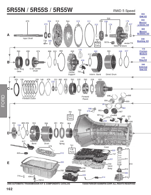
1622008 AUTOMATIC TRANSMISSION KIT & COMPONENTS CATALOG ©2008 PARKER HANNIFIN CORP. ALL RIGHTS RESERVED3790103008397797405R55N / 5R55S / 5R55WRWD 5 SpeedA544510034070670Input ShaftO.Dr. Ring GearO.Dr. CenterShaft783Center SupportInterm. BandDirect DrumForward ClutchForward PlanetReverse BandReverse DrumLow Sprag310037179520036178530311914363912911913910896904896437490996V.B.Parts741E414494765-6370Case313321320Valve Body917747765746322420002OHK Kit004Master L/Steels Kit 006Master 030External Seal Kit1632008 AUTOMATIC TRANSMISSION KIT & COMPONENTS CATALOG ©2008 PARKER HANNIFIN CORP . ALL RIGHTS RESERVEDRWD 5 Speed5R55N / 5R55S / 5R55W862981971961560961971985879565126106146861*229964974877564285872962972104124552894Intermediate Sprag690074266Park Gear264847Park Pawl Assy995-1995-2995-3995916-2916-3919922915916-2916-3919922916263EDA181554770Ext. Hsg.781493305678Output ShaftO.Dr. Band StrutInterm. Band Strut268841Internal Linkage991-2991-3994799991-4761P-4991072410992Yoke1642008 AUTOMATIC TRANSMISSION KIT & COMPONENTS CATALOG©2008 PARKER HANNIFIN CORP. ALL RIGHTS RESERVED*Prefix Letter ‘T’ denotes Toledo-Trans Kit (TTK) Brand Transmission Kits *Prefix Letter ‘B’ denotes Bryco Brand Transmission Kits002.............T16002AP......Overhaul Kit, 5R55N (With Bonded Pistons) 1999-Up ..............................................................1..........002.............T16002GP......Overhaul Kit, 5R55S/5R55W (With Bonded Pistons) 2002-Up..................................................1..........004.............T16004AP......Master L/Steels Kit, 5R55N (With Bonded Pistons) 1999-Up ....................................................1..........004.............T16004GP......Master L/Steels Kit, 5R55S/5R55W (With Bonded Pistons) 2002-Up .......................................1..........006.............T16006AP......Master W/Steels Kit, 5R55N (With Bonded Pistons) 1999-Up...................................................1..........006.............T16006GP......Master W/Steels Kit, 5R55S/5R55W (With Bonded Pistons) 2002-Up ......................................1..........E300...........45019............Gasket, 5R55N Bottom Pan (Plastic With Silicon Bead) OE Style (With Large Holes) 1999-Up 1..........XW4Z-7A191CA D305...........45097668......Gasket, 5R55N/5R55S/5R55W Extension Housing To Case 1999-Up......................................1..........XW4Z-7086-AA A309..........41217............Gasket, 5R55N/5R55S/5R55W Pump Bolt Washer...................................................................AR ........A310..........45097667......Gasket, 5R55N/5R55S/5R55W Pump 1999-Up..........................................................................1..........XW4Z-7A136AB A311...........1988096........O-Ring, 5R55N/5R55S/5R55W Pump Cover 1999-Up ...............................................................1..........XW4Z-7A248AA A313..........1994747........O-Ring, 5R55N Inner Pump Gear 1999-Up.................................................................................1..........F77Z-7L323AA E320...........45097692......Gasket, 5R55N Valve Body Separator Plate To Case 1999-Up ................................................1..........XW4Z-7D100-BF E320...........45097738......Gasket, 5R55S/5R55W Valve Body Separator Plate To Case (Upper) 2002-Up......................1..........1L2Z-7Z490AB-1A070..........70243V..........Seal, 5R55N/5R55S/5R55W Front (No Flange) (Rubber Coated) 1999-Up ..............................1..........F77Z-7A248AA D072...........70083............Seal, 5R55N Linkage 1999-Up ..................................................................................................1..........D5AZ-7B498A D074...........70283............Seal, 5R55N Rear 2WD 2000-Up ...............................................................................................1..........XW4Z-7052AA D074...........70205............Seal, 5R55S/5R55W Rear (W/Long Boot) 2WD 2002-Up .........................................................1..........F6UZ-7052A D074...........70282............Seal, 5R55S/5R55W Extension Housing 4X4 2002-Up .............................................................1..........1L2Z-7052BA175.............6358..............Ring Kit, 5R55N/5R55S/5R55W (2 Metal 4PTFE 2 Torlon Rings) 1999-Up ...............................1..........A178..........45060279......Ring, 5R55N, 5R55W, 5R55S Pump Support (Lock-Up) 1999-Up .............................................1..........B181...........TAW- 2212....Ring, 5R55N, 5R55W, 5R55S Forward Clutch Cylinder 1999-Up .............................................2..........D184...........45060265......Ring, 5R55N, 5R55W, 5R55S Output Shaft 1999-Up.................................................................1..........A179..........30308............Ring, 5R55N, 5R55W, 5R55S Overdrive Brake Drum 1999-Up.................................................2..........B179...........30308P ..........Ring, 5R55N, 5R55W, 5R55S Direct Clutch (Center Support) 1999-Up Torlon .........................2..........119.............45082NR........Friction Module, 5R55N 1999-Up................................................................................................1..........119.............45082LR........Friction Module, 5R55S/5R55W 2002-Up...................................................................................1..........E010...........45040N ..........Filter, 5R55N (3/8” Tall Pick-up Tube) 1999-Up ..........................................................................1..........XW4Z-7A098BB E010...........F-340.............Filter, 5R55S/5R55W (2 1/4” Tall Pick-Up Tube) 2002-Up..........................................................1..........1L2Z-7A098AC5R55N / 5R55S / 5R55WRWD 5 Speed1652008 AUTOMATIC TRANSMISSION KIT & COMPONENTS CATALOG ©2008 PARKER HANNIFIN CORP. ALL RIGHTS RESERVEDB022...........45090............Band, 5R55N Overdrive/Intermediate (Hi-Energy) 1999-Up......................................................2..........XW4Z-7D034BA 030.............45030G..........Bushing Kit, 5R55N/5R55S/5R55W 1999-Up.............................................................................1..........A034..........31530............Bushing, 5R55N/5R55S/5R55W Pump Cover 1999-Up .............................................................1..........A036..........31531............Bushing, 5R55N/5R55S/5R55W Overdrive Sun Gear 1999-Up................................................1..........A036..........45039............Bushing, 5R55N/5R55S/5R55W Stator (Front) 1999-Up ...........................................................1..........A037..........31532............Bushing, 5R55N/5R55S/5R55W Stator (Rear) 1999-Up............................................................1..........A046..........31533............Bushing, 5R55N/5R55S/5R55W Coast Clutch Drum e 56036A................................................................................................................................1..........B211...........45176A..........Washer, 5R55N/5R55S/5R55W Pump To Coast Clutch Drum .063" (Plastic) 1999-Up.............1..........F7TZ-7D014TA B211...........45176B ..........Washer, 5R55N/5R55S/5R55W Pump To Coast Clutch Drum .071" (Plastic) 1999-Up.............1..........F7TZ-7D014MA B211...........45176C ..........Washer, 5R55N/5R55S/5R55W Pump To Coast Clutch Drum .075" (Plastic) 1999-Up.............1..........F7TZ-7D014NA B211...........45176D ..........Washer, 5R55N/5R55S/5R55W Pump To Coast Clutch Drum .079" (Plastic) 1999-Up.............1..........F7TZ-7D014PA B211...........45176E ..........Washer, 5R55N/5R55S/5R55W Pump To Coast Clutch Drum .083" (Plastic) 1999-Up.............1..........F7TZ-7D014RA B211...........45176F ..........Washer, 5R55N/5R55S/5R55W Pump To Coast Clutch Drum .087" (Plastic) 1999-Up.............1..........F7TZ-7D014SA C232...........45145............Washer, 5R55N/5R55S/5R55W Bearing to Forward Hub (Solid Bronze) 1999-Up .................1..........FOTZ-7D090A D263...........45077............Washer, 5R55N/5R55S/5R55W Parking Gear To Case 1999-Up ..............................................1..........D4ZZ-7B368-AD410...........D56955J ........Switch, 5R55N Neutral Safety (12 Prong Connector) 1999-Up ...............................................1..........XW4Z-7F293AA E922...........33991............Nut, 5R55N/S/W Band 1999-Up .................................................................................................2..........380850-SRWD 5 Speed5R55N / 5R55S / 5R55W。


Easy Start364 (3 ton) Soft Starter368 (6 ton) Soft StarterInstallation ManualMicro Air Corporation Phone (609) 259-2636 124 Route 526. Allentown NJ 08501 Fax (609) 259-6601Retrofit Instructions1.Read and understand these instructions completely before proceeding.2.Improper wiring can result in damage to EasyStart or connected components including but not limited towiring, compressors, and capacitors. Micro Air Corp is not responsible for damages to any of theaforementioned equipment caused by improper wiring.3.Turn off the breaker for the compressor’s electrical system.4.Consult the manufacture’s installation manual and wiring diagram for the identification of the following:a.Start capacitor (typically in a plastic can), start relay, or compressor start device. Note that thesedevices may NOT be installed on some systems.b.Run capacitor (typically in a metal can). Most have 2, multi-point terminal connections (orclusters). Some have 3 terminal connections.c.Control board switched-L1 output or main contactor compressor L1 output connecting to thecompressor common terminal (C) wire. Note some systems utilize a contactor to switch power tothe compressor, other use a power relay integrated into the main control board.5.If the system utilizes a start capacitor with a start relay, or a start assist device, disconnect all the wiringconnected to the start capacitor or the start assist and remove them from the electric box. Be aware thatsome connections to the compressor (e.g. compressor common L1 and compressor Run L2) may havejunction connections at terminals of the start relay. Therefore, it is best to NOT remove the start relayunless you are able to trace out these wiring junctions and splice them. Disconnecting and removing only the start capacitor from a system with a start cap and start relay will effectively disable the start relay, thus eliminating the need for it being removed.6.Locate the compressor run capacitor. Locate the wire connected from the run capacitor to the compressorrun winding terminal (R), and disconnect it from the run capacitor. Connect (splice) the brown wire from EasyStart to the disconnected wire.7.Connect the white wire from EasyStart to the same terminal of the run capacitor from which youdisconnected the (white) run winding (R) wire in step 6 above.8.Connect the orange wire from EasyStart to the terminal on the run capacitor that connects to thecompressor start winding terminal (S). If the run capacitor is a dual, compressor/fan type, make sure tochoose the correct capacitor terminal, typically labeled “COMP”, “C”, Herm, or “H”.9.Connect the black wire from EasyStart to the switched-L1 connection emanating from the main controlboard or main contactor that typically has a black or purple wire that connects to the compressor common(C) terminal wire.10.Wiring is now complete. Remove any remaining unused or disconnected wires and close all open electricalboxes and panels.11.Securely mount the EasyStart using the four holes provided on the mounting flange, locating it close to theoriginal system electric box (limited by wire harness length).12.Turn on the system circuit breaker using shore power. Start a heating or cooling cycle with the thermostat.13.EasyStart will now learn the characteristics of the compressor for the next five starts. This operation will bedone during normal operation and does not require any intervention or special actions. Once the learning process is completed, the EasyStart can be operated on either shore or generator power. During the learning starts, be sure to allow enough off time between starts for pressures to equalize. Equalization occurs in most systems within five minutes so we advise waiting at least five minutes between starts.IMPORTANT INSTALLATION NOTE FOR CRUISAIR® MARINE CUSTOMERS ONLY: When installing EasyStart into 230V SMX control applications that use the triac to switch power to the compressor, it is necessary to replace the triac with a relay. If the triac is not replaced, the pump relay triggers may suffer damage and ultimately fail. Please notr that this is not required for 115V SMX applications and the triac is still safe to use. See the Microair Webstore or contact Microair for details on the appropriate relay.Example EasyStart Installation Wiring Diagram:Jumper Usage:A six pin diagnostic header is located inside the EasyStart box. Most installations will not need to access this header.Jumpers may be placed on JP1 for certain special functions. Place jumpers only asshown below.Normal:Most operation should be done without a jumper installed on JP1 or with the jumperinstalled across pins 3 and 4 as shown.Default:A compressor may be operated with a factory defined start characteristic. This maynot be the optimal start for the connected compressor and is generally used for factorydiagnostics. No optimization is done with this setting.Relearn:If a compressor, start capacitor, or run capacitor is replaced, place a jumper onpins 4 and 6 as shown. Cycle power on then off again and replace the jumper in the “Normal”position. Follow step 13 of the retrofit instructions to complete the relearn process.Disable:This setting disables the microprocessor on the board so no operation can occur. Anti-Short Cycle Timer:EasyStart models incorporate a timer that prevents immediate restarts.This feature was added to prevent overheating of the start capacitor and reducefaults due to un-equalized pressures in the system. Restart will take up to 5minutes if power is removed then reapplied.Later models include a wire jumper JP2 (see picture on right) that canbe cut to eliminate this feature. System controls must be sufficient to prevent short cycling if this jumper is cut. Warning: Starts must be limited to 1 start every 5 minutes with pressures equalized if JP2 is cut.EasyStart Troubleshooting:Wiring Evaluation:A ll start components from the original installation are removed including PTC’s and startcapacitors.The Brown wire from EasyStart connects directly to the compressor run winding.The Black wire from EasyStart is spliced to the thermostat relay feeding the compressor overloadprotector on the compressor common terminal.The Orange wire from EasyStart is connected to the compressor run capacitor on the same side asthe compressor start winding.The White wire from EasyStart is connected to the AC-L2 or AC-N side of the compressor runcapacitor.Trouble Lights:Three diagnostic lights are provided inside the EasyStart box on the printed circuit board. These lights are labeled in white silkscreened letters next to the light. When a fault is detected, EasyStart willilluminate one or more lights to indicate which fault occurred. All faults except over current will reset after3 minutes. Over current is reset by removing power from EasyStart and reapplying power. Users will notnormally need to view these lights. The chard below defines the lights that are turned on for each fault.Fuses:Protection fuses are installed in the start circuit to prevent damage due to miswiring or start capacitorfailure. If this fuse fails in normal operation, there is most likely a problem with the start capacitor which should be replaced along with the fuse.364 (3 ton)1.Revision H and earlier boards: These boards incorporate a non-replaceable fuse inthe start circuit. These units must be returned to Microair for repair.2.Revision I and above boards: These boards incorporate a replaceable 15A 250Vrated, slow blow, 5mm x 20mm glass fuse.368 (6 ton)1.Revision E and earlier boards: These boards incorporate a non-replaceable fuse inthe start circuit. These units must be returned to Microair for repair.2.Revision F and above boards: These boards incorporate a replaceable 30A 250VACrated 3AB, 3AG, ¼” x 1 ¼” (6.35mm x 31.75mm) slow blow ceramic fuse.FAQ:What is re-learning?The re-learning process simply clears the EasyStart memory and returns it to as shipped condition. EasyStart should be re-learned whenever a compressor is changed or if pressures were not allowed to equalize during the learning process.To re-learn EasyStart, remove power and open the EasyStart box. Locate the 6 pin header shown in the jumper usage section of this manual and place the shorting jumper over pins 4 and 6 as shown. Start a cycle with your thermostat with the compressor powered from AC mains and allow EasyStart to start the compressor. Remove power once the compressor starts and replace the jumper to the stored position over pins 3 and 4. Replace the cover on EasyStart and complete at least 4 additional starts. Be sure to allow time for pressures to equalize between starts, usually 3 to 5 minutes.Be sure to remove the jumper from pins 4 and 6 and replace it to pins 3 and 4 immediately after the FIRST start and after power is removed.I connected everything and it just won’t start. What do I do now?First, do the wiring evaluation in this section. Wiring should be exactly as shown in the sample diagram with no left over start components. If there are any questions about wiring your unit, you can send a wiring diagram for your compressor to **************** along with your question.Be sure you are only using regular AC line power and not a generator or inverter for the first five starts. The first starts on EasyStart are usually higher than the final start and can overload marginal supplies and prevent EasyStart from learning the best start for your compressor.Check for any trouble lights. If any are illuminated, identify the reason EasyStart is not starting your compressor. Most times trouble lights point to a problem with the wiring.What does a “S talled” indication from EasyStart mean?Stalled means EasyStart is not seeing the condition where it can declare that the compressor is running and connect the compressor directly. The first thing to do is the wiring evaluation above.Stalled can also be caused by an improperly sized or bad start capacitor. 3T systems with 220 volt 12K BTU and smaller compressors may require smaller value start capacitors. Contact Microair prior to purchase to determine requirements for these systems.What d oes “Power Interruption” mean?Power was lost for several AC cycles of power and EasyStart shut down. Compressors will stall after only a few lost cycles creating a huge load when power is restored. EasyStart prevents this excessive load by preventing operation for 3 minutes. EasyStart will restart the compressor following this delay.We have found that some power conditioning equipment uses relays to switch taps on a transformer may switch too slowly to properly run a compressor.What does “Start winding not detected-EasyStart is miswired” mean?One of the following:The orange wire is not connected to the start winding.The Compressor Start winding is open.Line L2 is connected to the compressor start winding.COPYRIGHT© 2017 Micro Air Corporation, All Rights ReservedNo part of this publication may be reproduced, translated, stored in a retrieval system, or transmitted in any form or by any means electronic, mechanical, photocopying, recording or otherwise without prior written consent by Micro Air Corporation.Every precaution has been taken in the preparation of this manual to insure its accuracy. However, Micro Air Corporation assumes no responsibility for errors and omissions. Neither is any liability assumed nor implied for damages resulting from the use or misuse of this product and information contained herein.。

March 2009Product Family OverviewProduct DescriptionFreedom Series starters and contactors feature a compact, space-saving design, using state-of-the-art technology and the latest in high strength, impact and temperature resistant insulating materials.FeaturesFreedom NEMA■Adjustable Bimetallic AmbientCompensated Overload relays with interchangeable heater packs — available in three basic sizes,covering applications up to 900 hp — reducing the number of different contactor/overload relay combina-tions that have to be stocked. Fixed heater overloads are optional.■Electronic Solid-State Overload Relay (C396) available as a stand-alone unit and assembled with Freedom Contactor.■ A full line of snap-on accessories common to both IEC and NEMA devices — top and side mounted auxiliary contacts, solid-state and pneumatic timers, etc.■Straight-through wiring — line lugs at top, load lugs at bottom.■Horizontal or vertical mounting on upright panel for application freedom.■Screw type power terminals have captive, backed-out self-lifting pres-sure plates with ± screws — reduced wiring time.■Accessible terminals for easy wir-ing. Optional fingerproof shields available to prevent electrical shock.■Top located coil terminals conve-nient and readily accessible. 45 mm contactor magnet coils have three terminals, permitting either top or diagonal wiring — easy to replace European or U.S. style starters or contactors without changing wiring layout.■Encapsulated dual voltage/frequency magnet coils —permanently marked with voltage, frequency and part number. NEMA Sizes 00 – 0 have non-encapsulated coils as standard.■Designed to meet or exceed NEMA, UL, CSA, VDE, BS and other interna-tional standards and listings.■American engineering — built by Eaton, using the latest in statistical process control methods to produce high quality, reliable products.■Sized based on standard NEMA classifications.■Easy coil change and inspectable/replaceable contacts.■Available in Open and NEMA Type 1, 3R, 4/4X and 12 enclosures.Standards and Certifications■Standard: Designed to meet or exceed UL, NEMA, IEC, CSA, VDE and BS.■UL listed: UL File #E1491, Guide #NLDX — Open and NEMA 1, 4, 12 Enclosed■CSA Certified: CSA File #LR353, Class #321104 Open and NEMA 1 EnclosedISO 9000 CertificationWhen you turn to Eaton’s Cutler-Hammer Products, you turn to quality. The International Standards Organiza-tion (ISO) has established a series of standards acknowledged by 91 indus-trialized nations to bring harmony to the international quest for quality. The ISO certification process covers 20 quality system elements in design, production and installation that must conform to achieve registration. This commitment to quality will result in increased product reliability and total customer satisfaction.Short Circuit ProtectionFuses and Inverse-Time Circuit Breakers may be selected per Article 430, Part D of the National Electrical Code to pro-tect motor branch circuits from fault conditions. If higher ratings or settings are required to start the motor, do not exceed the maximum as listed in Exception No. 2, Article 430-52.NEMA AN16DN0AB NEMA Size 1 StarterNEMA Size 1 ContactorSeries B1 32A OverloadC396 Electronic OverloadMarch 2009Starters — 3-Phase Non-reversing and Reversing, Full VoltageContentsDescriptionPageProduct Family OverviewProduct Description. . . . . . 33-68Features . . . . . . . . . . . . . . . 33-68Standards andCertifications . . . . . . . . . . 33-68Catalog NumberSelection . . . . . . . . . . . . . 33-69Starters — 3-Phase Non-reversing and Reversing, Full Voltage, Bi-Metallic OverloadProduct Description. . . . . . 33-73Features . . . . . . . . . . . . . . . 33-73Technical Data . . . . . . . . . . 33-74Wiring Diagrams . . . . . . . . 33-74Product Selection. . . . . . . . 33-75Starters — 3-Phase Multispeed, Bi-Metallic OverloadProduct Selection. . . . . . . . 33-76Starters — Single-PhaseNon-reversing, Full Voltage, Bi-Metallic OverloadProduct Description. . . . . . 33-77Wiring Diagrams . . . . . . . . 33-77Product Selection. . . . . . . . 33-77Starters — 3-Phase Non-reversing and Reversing, Full Voltage,C386 Electronic Overload . . 33-78Technical Data . . . . . . . . . . . . . 33-79Accessories . . . . . . . . . . . . . . . 33-82Auxiliary Contacts . . . . . . . 33-86DC Magnet Coils . . . . . . . . 33-88Mounting Plates. . . . . . . . . 33-89Special Modifications . . . . . . . 33-90Renewal Parts . . . . . . . . . . . . 33-91Dimensions . . . . . . . . . . . . . . . 33-94Product DescriptionNon-reversingThree-phase, full voltage magnetic starters are most commonly used to switch AC motor loads. Starters con-sist of a magnetically actuated switch (contactor) and an overload relay assembled together.ReversingThree-phase, full voltage magnetic starters are used primarily for revers-ing of 3-phase squirrel cage motors. They consist of two contactors and a single overload relay assembledtogether. The contactors are mechani-cally and electrically interlocked to prevent line shorts and energization of both contactors simultaneously.Features■Bimetallic Ambient Compensated Overload relays — available in three basic sizes covering applications up to 900 hp — reducing number of different contactor/overload relay combinations that have to be stocked.These overload relays feature:❑Selectable Manual or Automatic Reset operation.❑Interchangeable heater packs adjustable ±24% to match motor FLA and calibrated for 1.0 and 1.15 service factors. Heater packs for smaller overload relay will mount in larger overload relay — useful in derating applications such as jogging.❑Load lugs built into relay base.❑Single-phase protection, Class 20 or Class 10 trip time.❑Overload trip indication.❑Electrically isolated NO-NC con-tacts (pull RESET button to test).■The C396 is a self-powered, robust electronic overload designed for integrate use with Freedom NEMA contactors.❑Tiered feature set to provide cov-erage specific to your application.❑Broad 5:1 FLA range for maxi-mum flexibility.❑Coverage from 0.05 – 1500 Amps to meet all your needs.■Long life twin break, silver cadmium oxide contacts — provide excellent conductivity and superior resistance to welding and arc erosion. Gener-ously sized for low resistance and cool operation.■Designed to 3,000,000 electrical operations at maximum hp ratings up through 25 hp at 600V.■Steel mounting plate standard on all open type starters.■Wired for separate or common control.Non-reversing■Holding circuit contact(s) supplied as standard:❑Sizes 00 – 3 have a NO auxiliary contact block mounted on right-hand side (on Size 00, contact occupies 4th power pole position — no increase in width).❑Sizes 4 – 5 have a NO contact block mounted on left side.❑Sizes 6 – 7 have a 2NO/2NC contact block on top left.❑Size 8 has a NO/NC contact block on top left back and a NO on top right back.Reversing■Each contactor (Size 00 – 8) supplied with one NO-NC sidemounted contact block as standard. NC contacts are wired as electrical interlocks.NEMA Size 1 — Cat. No. AN16DN0ABNEMA Size 1 — Cat. No. AN56DN0ABMarch 2009Starters — 3-Phase Non-reversing and Reversing, Full VoltageTechnical DataTable 33-96. Wire (75°C) Sizes — AWG or kcmil — NEMA Sizes 00 – 2 — Open and EnclosedᕃTwo compartment box lug.ᕄMinimum per NEC. Maximum wire size: Sizes 00 and 0 to 8 AWG and Sizes 1 – 2 to 2 AWG.Table 33-97. Wire (75°C) Sizes — AWG or kcmil — NEMA Sizes 3 – 8 — Open and EnclosedᕅMinimum per NEC. Maximum wire size: Sizes 00 and 0 to 8 AWG and Sizes 1 – 2 to 2 AWG.Wiring DiagramsFigure 33-24. Typical Wiring Diagrams — Three-Phase and Single-Phase ApplicationsNEMA SizeWire Size ᕄ Cu OnlyPower Terminals — Line0001212 – 16 AWG stranded, 12 – 14 AWG solid 8 – 16 AWG stranded, 10 – 14 AWG solid 8 – 14 AWG stranded or solid3 – 14 AWG (upper) and/or 6 – 14 AWG (lower) stranded or solid ᕃPower Terminals — Load — Cu Only (stranded or solid)00 – 01 – 214 – 6 AWG stranded or solid 14 – 2 AWG stranded or solidControl Terminals — Cu Only12 – 16 AWG stranded, 12 – 14 AWG solidNEMA SizeWire Size ᕅPower Terminals — Line and Load31/0 – 14 AWG Cu/Al4Open — 3/0 – 8 AWG Cu; Enclosed — 250 kcmil — 6 AWG Cu/Al 5678750 kcmil — 2 AWG; or (2) 250 kcmil — 3/0 AWG Cu/Al (2) 750 kcmil — 3/0 AWG Cu/Al (3) 750 kcmil — 3/0 AWG Cu/Al (4) 750 kcmil — 1/0 AWG Cu/AlControl Terminals — Cu Only12 – 16 AWG stranded, 12 – 14 AWG solidTable 33-98. Plugging and Jogging Service Horsepower Ratings ᕆᕆMaximum horsepower where operation is interrupted more than 5 times per minute, or more than 10 times in a 10 minute period. NEMA Standard ICS2-1993 table 2-4-3.Kits and Accessories■Auxiliary Contacts, contactor mounted — Pages 33-86 – 33-87. ■Transient Suppressor, for magnet coil — Pages 33-84.■Timers — Solid-State andPneumatic, mount on contactor — Page 33-83.Renewal Parts Publication Numbers■See Page 33-91.NEMA Size 200V 230V 460V 575V 000123—1-1/237-1/2151/21-1/2310201/22515301/2251530456256012530751506015030060150300March 2009Starters — 3-Phase Non-reversing and Reversing, Full Voltage, Bi-Metallic OverloadProduct SelectionWhen Ordering Supply■Catalog Number■Heater pack number (see selectiontable, Pages 33-107 – 33-108) or full load current.Table 33-99. Type AN16/AN56 NEMA — Manual or Automatic Reset Overload Relay — Non-reversing and ReversingNote: Starter Catalog Numbers do not include heater packs. Select one carton of three heater packs. Heater pack selection, Pages 33-107 – 33-108.ᕃUnderscore (_) indicates coil suffix required, see Table 33-100.ᕄMaximum horsepower rating of starters for 380V 50 Hz applications: ᕅThe service-limit current ratings represent the maximum rms current, in amperes, which the controller shall be permitted to carry for protracted periods in normal service. At service-limit current ratings, temperature rises shall be permitted to exceed those obtained by testing the controller at itscontinuous current rating. The current rating of overload relays or trip current of other motor protective devices used shall not exceed the service-limit current rating of the controller.ᕆCommon control. For separate 120V control, insert letter D in 7th position of listed Catalog Number. EXAMPLE: AN56VN D 0CB.Magnet Coils — AC or DCStarter coils listed in this section also have a 50 Hz rating as shown in the adjacent table. Select required starter by Catalog Number and replace the magnet coil alpha designation in the Catalog Number (_) with the proper Code Suffix from the adjacent table.For Sizes 00 – 2 and 5 – 8, the magnet coil alpha designation will be the next to last digit of the listed Catalog Num-ber. EXAMPLE: For a 380V, 50 Hz coil, change AN16BN0_C to AN16BN0L C. For all other sizes, the magnet coil alpha designation will be the last digit of the listed Catalog Number.For DC Magnet Coils , see Accessories, Pages 33-88 – 33-89.Table 33-100. AC Suffix CodeᕇNEMA Sizes 00 and 0 only.ᕈNEMA Sizes 00 and 0 only. Sizes 1 – 8 are 24/60 only.NEMA Size Continuous Ampere Rating Service-Limit CurrentRating ᕅ(Amperes)Maximum UL Horsepower ᕄ3-PoleNon-reversing ᕃ3-PoleReversing ᕃVerticalReversing ᕃPrice U.S. $1-Phase3-Phase115V 230V 208V 240V 480V 600V CatalogNumber Price U.S. $Catalog Number Catalog Number 009111/311-1/21-1/222AN16AN0_C AN56AN0_C —01821123355AN16BN0_C AN56BN0_C AN56BNV0_12732237-1/27-1/21010AN16DN0_B AN56DN0_B AN56DNV0_2455237-1/210152525AN16GN0_B AN56GN0_B AN56GNV0_390104——25305050AN16KN0_AN56KN0_AN56KNV0_4135156——4050100100AN16NN0_AN56NN0_AN56NNV0_5270311——75100200200AN16SN0_B AN56SN0_B —6540621——150200400400AN16TN0_C AN56TN0_C —7810932——200300600600AN16UN0_B AN56UN0_B —8 ᕆ12151400——400450900900AN16VN0_BAN56VN0_B—NEMA Size 00012345678Horsepower1-1/2510255075150300600900Size 0Non-reversing StarterSize 1Reversing StarterSize 3 Vertical Reversing StarterNEMA Size 0Cat. No. AN56BN0ACCoil Volts and Hertz Code Suffix 120/60 or 110/50240/60 or 220/50480/60 or 440/50600/60 or 550/50A B C D 208/60277/60208 – 240/60 ᕇ240/50E H J K 380 – 415/50550/5024/60, 24/50 ᕈ24/50L N T U 32/5048/6048/50V W YTechnical Data. . . . . . . . . . Pages 33-79 – 33-81Overload Relay . . . . . . . . . Page 33-103Dimensions . . . . . . . . . . . . Pages 33-96 – 33-98Special Modifications . . . Page 33-90Accessories. . . . . . . . . . . . Pages 33-82 – 33-90March 2009Starters — Single-Phase Non-reversing, Full Voltage, Bi-Metallic OverloadProduct DescriptionSingle-phase, full voltage magnetic starters connect the motor directly across the line, allowing it to draw full inrush current during start-up. These starters are most commonly used for control of self-starting single-phase motors up to 15 horsepower at 230V. They consist of a 2-pole electromag-netic contactor to make and break the motor power circuit and an overload relay to provide running overload protec-tion. Starters listed in the table include:■Two-pole Freedom Series contactor with long life twin break, silver cadmium oxide contacts. Generously sized for low resistance and cool operation. Designed to 3 mil-lion electrical operations at maximum hp and 30 million mechanical operations to Size 0, 10 million operations to Size 2 and 6 million operations to Size 3.■Three-pole Freedom Series overload with poles 2 and 3 wired in series for motor overload protection. This over-load is ambient compensated, selectable Manual or Auto-matic reset, interchangeable Class 10 or 20 heater packs, 1.0 or 1.15 service factor selectability, overload trip indica-tion and electrically isolated NO-NC contacts (pull RESET button to test).■Holding circuit NO auxiliary contact supplied as standard. On Size 00, the contact occupies the 4th power pole position. Sizes 0 – 3 have the NO auxiliary mounted on the right side of the contactor.■Steel mounting plate as standard on all open type starters. Wired for separate or common control.Wiring DiagramsFigure 33-25. Typical Wiring Diagrams — Single-Phase Applications (Factory Wired)Product SelectionWhen Ordering Specify■Catalog Number■Heater Pack Number (see selection table, Pages 33-107 – 33-108) or full load current.Table 33-104. Type BN16 NEMA — Manual or Automatic Reset Overload RelayNote: Starter Catalog Numbers do not include heater packs. Select 1 carton of 3 heater packs. Heater pack selection, Pages 33-107 – 33-108.ᕃFor separate 120V control circuit. For maximum hp at listed motor voltages, use the rating of other starters of same size.NEMA Size 1 — Cat. No. BN16DN0ABNEMA SizeMaximum Horsepower MagnetCoil Voltage (60 Hz)Open Type 2-Pole Motor Voltage 1-Phase Catalog Number Price U.S. $001152301/31120 ᕃ240BN16AN0AC BN16AN0BC 011523012120 ᕃ240BN16BN0AC BN16BN0BC 111523023120 ᕃ240BN16DN0AB BN16DN0BB 1P 11523035120 ᕃ240BN16PN0AB BN16PN0BB 211523037-1/2120 ᕃ240BN16GN0AB BN16GN0BB 31152307-1/215120 ᕃ240BN16KN0A BN16KN0BContentsDescriptionPage Thermal Overload RelaysProduct Description. . . . . . 33-103Features . . . . . . . . . . . . . . . 33-103Operation . . . . . . . . . . . . . . 33-103Technical Information . . . . 33-103Technical Data . . . . . . . . . . 33-104Factory Modifications . . . . 33-105Accessories. . . . . . . . . . . . . 33-105Replacement Parts. . . . . . . 33-105Dimensions. . . . . . . . . . . . . 33-106Product Selection. . . . . . . . 33-107Heater Pack Selection . . . .33-107Product DescriptionC306 Overload Relays are designed for use with CE or CN non-reversing and reversing contactors. Four sizes are available for overload protection up to 144A.Features■Selectable Manual or Automatic Reset operation.■Interchangeable Heater Packs adjustable ±24% to match motor FLA and calibrated for use with 1.0 and 1.15 service factor motors.Heater packs for 32A overload relay will mount in 75A overload relay — useful in derating applications such as jogging.■Class 10 or 20 heater packs.■Load lugs built into relay base.■Bimetallic, ambient compensated operated. Trip free mechanism.■Electrically isolated NO-NC contacts (pull RESET button to test).(Electrical Ratings see Table 33-158 on Page 33-104).■Shrouded or fingerproof terminals to reduce possibility of electrical shock.■Meets UL 508 single-phasing requirements.■UL listed, CSA certified, NEMA compliance and CE mark.OperationC306 Overload Relay SettingFigure 33-43. FLA Dial AdjustmentFor motors having a 1.15 service fac-tor, rotate the FLA adjustment dial to correspond to the motor’s FLA rating. Estimate the dial position when the motor FLA falls between two letter values as shown in the example.For motors having a 1.0 service factor, rotate the FLA dial one-half position counterclockwise (CCW).Figure 33-44. Manual/Automatic Reset The overload relay is factory set at M for manual reset operation. For auto-matic reset operation, turn the reset adjustment dial to the A position as shown in the illustration.Automatic reset is not intended for two-wire control devices.Test for Trip IndicationTo test overload relay for trip indica-tion when in manual reset, pull out the blue reset button. An orange flag will appear indicating that the device has tripped. Push reset button in to reset.Warning — To provide continued pro-tection against fire or shock hazard, the complete overload relay must be replaced if burnout of the heater element occurs.Technical InformationGeneral“Overload relays are provided to pro-tect motors, motor control apparatus and motor-branch circuit conductors against excessive heating due to motor overloads and failure to start. This definition does not include:1) motor circuits over 600V,2) short circuits,3) ground faults and 4) fire pump control.” (NEC Art. 430-31)Time Current CharacteristicsThe time-current characteristics of an overload relay is an expression of per-formance which defines its operating time at various multiples of its current setting. Tests are run at Underwriters Laboratories (UL) in accordance with NEMA Standards and the NEC. UL requires:■When tested at 100 percent of its current rating, the overload relay shall trip ultimately.■When tested at 200 percent of its current rating, the overload relay shall trip in not more than 8 minutes.■When tested at 600 percent of the current rating, the overload relay shall trip in not more than 10 or 20 seconds, depending on the Class of the relay.“Current Rating” is defined as the minimum current at which the relay will trip. Per NEC, an overload must ultimately trip at 125% of FLA current (heater) setting for a 1.15 service factor motor and 115% FLA for a 1.0 service factor motor.“Current Setting” is defined as the FLA (Full Load Amperes) of the motor and thus the overload heater pack setting.Example: 600% of current rating is defined as 750% (600 x 1.25) of FLA current (heater) setting for a 1.15 ser-vice factor motor. A 10A heater setting must trip in 20 seconds or less at 75A 32A OverloadCat. No. C306DN3BProduct SelectionTable 33-166. C306 Thermal Overload RelaysᕃNEMA Sizes 5 – 8 use the 32A overload in conjunction with CTs.ᕄSeries B overload relays have load lugs built into relay base and will only accept Series B heater packs. These relays can be directly attached to contactor or they can be DIN rail or panel mounted using adapter on Page 33-105.ᕅThese relays can be panel mounted only.Table 33-167. C306 Thermal Overload RelaysᕆOverload relay assembled with mounting adapter for DIN rail or panel mount.ᕇPanel mount only.ᕈNEMA Sizes 5 – 8 use the 32A overload in conjunction with CTs.Heater Pack SelectionHeater packs H2001B to H2017B and H2101B to H2117B are to be used only with Series B overload relays Catalog Numbers C306DN3B (Part No. 10-7016) and C306GN3B (Part No. 10-7020). The load lugs are built into the overload relay base to allow load wiring prior to heater pack installa-tion. The previous heater design had integral load lugs. The Series B heater packs are electrically equivalent to the previous heater design. Heaters H2018-3 to H2024-3 have not changed.Table 33-168. Starters with Series B Overload RelaysNote: The series of a starter is the last digit of the listed Catalog Number. EXAMPLE: AN16DN0A B .For Use with Freedom Series Contactors Maximum Ampere RatingNumber of PolesOpen Type NEMA 1 Enclosed NEMA Size Catalog NumberPrice U.S. $Catalog Number Price U.S. $00, 01, 2345 – 8 ᕃ32 ᕄ75 ᕄ105 ᕅ144 ᕅ—3333—C306DN3B C306GN3B C306KN3C306NN3—C306DG3B C306GG3B —75A OverloadCat. No. C306GN3B 75A OverloadCat. No. C306GT3B 32A OverloadCat. No. C306DT3B 32A OverloadCat. No. C306DN3BFor Stand-Alone Applications Maximum Ampere RatingNumber of PolesOpen Type NEMA Size Catalog NumberPrice U.S. $00, 0, 1 ᕆ1 ᕆ3 ᕇ4 ᕇ5 – 8 ᕈ3275105144—3333—C306DT3B C306GT3B C306KN3C306NN3—Heater PackH2001B – H2017BHeater PackH2101B – H2117BHeater Pack H2018 – H2024NEMA — AN Type IEC — AE Type Size Series Size Series 00 – 01 – 2567 – 8C B B C BA – F G – KC BTechnical Data . . . . . . . . Page 33-104Dimensions. . . . . . . . . . . . Page 33-106。


2Geroler MotorsTools required for disassembly and reassembly.l Torque wrench (34Nm [300 Ib-in] capacity)l300-400mm [12-16 inch] breaker barl5/16-12 point socket no. 5422 (Heavy Duty-56Nm [500 Ib-in]capacity)l5/16 12 point socket no. 5422 (Heavy Duty-56Nm [500 Ib-in]capacity)l Small screwdriver (150-200 x 6mm [6-8 x .25 inch] flat blade), seepage 6 for tooling information.l3/16 inch [5mm] hex keyl Shaft pressure seal installation tool for -008 motor P/N 600470l Shaft pressure seal installation tool for -009 and -010 motors P/N600523l Seal sleeve or bullet P/N 600304 (1 inch dia. shaft), P/N 600466The following tools are not necessary for disassembly andreassembly but are extremely helpful.l Small propane torch*T ools available-by special order-through our service department.3Cleanliness is extremely important when repairing these motors.Work in a clean area. Before disconnecting the lines, clean port area of motor. Remove key when used. Check shaft and key slot, remove burrs nicks or sharp edges and polish around the key slot. Before starting disassembly, drain oil from motor, then plug ports and thoroughly clean exterior of motor.Although not all drawings show the motor in a vise, we recommend that you keep the motor in the vise during disassembly. Follow the clamping procedures explained throughout the manual.Disassembly3 Remove cap screws and seal washers from end cap (seal washers used on 59, 69 and 95 cm 3/r [3.6, 4.2 and 5.8 in 3/r] displacement motors only).4 Remove end cap.5 Remove seal from Geroler.6 Remove Geroler-retain rollers in the outer Geroler ring, see Fig. 3.7 Remove seal from Geroler, see Fig. 3.8 Remove drive spacer (not used on 95 and 159 cm 3/r [5.8 and 9.7in 3/r ] displacement motors for the -008 and -009 motors and not used on -010 motors).1 Place motor in vise, clamp across edge of flange with output shaft down. When clamping, use protective device on vise, such as special soft jaws, pieces of hard rubber or board, see Fig. 1.2 Some motors may have a case drain plug in the end cap. If external case drain is not used, it is not necessary to replace the seal unless leakage occurs.Figure 14Figure 3Figure 25Disassembly9 Remove spacer plate 10 Remove drive, see Fig. 4.11 Remove seal from housing.14 Remove motor from vise. Place on clean flat surface. Carefully lift flange from housing with a twisting motion.The screws will require approximately 34-45Nm [300-400 Ib-in] of torque to break loose and approximately 11 Nm [100 Ib-in] torque to remove after they are broken loose. Do not use an impact wrench on Loctited screws, this may result in rounded heads or broken sockets.NOTE: If higher torque than given above is required to break the screws loose, apply heat according to the following instruction. When heated the Loctite partially melts and the torque required to remove the screw is greatly reduced. Follow the instructions carefully , and be careful not to overheat and cause damage to the motor. Use a small flame propane torch to heat a small area of the housing, where the screw enters, see Fig. 6. Apply torque to the screw with a socket wrench gradually as heat is applied for 8 to 10 seconds. As soon as the screw breaks loose, remove heat from the housing and continue turning the screw until it is completely removed.Figure 6Figure 5Clamp across portsnot across housing. Excessive clamping pressure causes distorsion.12 Reposition motor in vise. Clamp across ports as shown in Fig. 5,not on side of housing. Do not over tighten jaws. Excessive clamping force may distort housing.13 Remove the 4 cap screws from the mounting flange. These motors are assembled using Loctite on the screws to hold them in place.Figure 4Disassembly15 The dust seal, pressure seal and oil seal will come off with the flange. Use a seal remover tool, like the one shown in Fig. 7, to remove the dust seal and pressure seal, as shown in Fig. 8 and 9. Work nose of tool between pressure seal and flange. Pry seal partway. Remove tool and repeat at a point 180° away. Push seal completely out of cavity, see Fig. 8.Figure 7Figure 8Figure 10Figure 916 Remove output shaft from housing.17 Remove bearing race and needle thrust bearing from shaft.18 Some older housings have plugs. T o remove the plug, use a 5mm [3/16 inch] hex key, inserted through port opening, to push them out.6Reassembly19 If you removed check valves, or plug(s), replace seal(s). Lubricate new seal(s). Install on check valves, or plug(s). Carefully push check valves, or plug(s), in housing until flush with housing face. Do not damage seal(s).20 Lubricate output shaft with clean hydraulic oil, then install shaft in housing.Important: Do not permit oil to get into the 4 tapped holes.Note: To help with timing procedures, a timing dot is machined on output shaft, see figures 18 and 19.21 Install needle thrust bearing then bearing race on shaft. Pull shaft partially out of housing, push all three parts in housing together. The bearing race must rotate freely when in position.Figure 11A. Wash the housing with non-petroleum base solvent to remove oil,grease and debris. Petroleum base solvents may leave residue detrimental to successful Loctiting. Pay particular attention to 4tapped holes on the flange end.Check all mating surfaces. Replace any parts that have scratches or burrs that could cause leakage or damage. Clean all metal parts in clean solvent. Blow dry with air. Do not wipe parts with cloth or paper towel, lint or other matter can get into the hydraulic system and cause damage. Check around the key slot and chamfered area of the shaft for burrs, nicks or sharp edges that can damage the seals when reassembling. Remove nicks or burrs with a hard smooth stone (such as an Arkansas stone). Do not try to file or grind motor parts.Note: Lubricate all seals with petroleum jelly such as Vaseline. Use new seals when reassembling the motor. Refer to parts list (No. 6-125) for proper seal kit number.Important: Do not stretch seals before installing. Cleanliness isextremely important in the successful application of Loctite. Use the following procedures to properly clean all parts.Note: Fully cured Loctite resists most solvents, oils, gasoline,kerosene, and is not affected by cleaning operations.B. Blow dry with compressed air. Clean and dry the tapped holes.Note: It is not necessary to remove the cured Loctite that is securely bonded in the tapped holes; however any loose particles of cured Loctite should be removed.C. Wire brush the screw threads to remove cured Loctite and other debris. Discard any screws that have damaged threads or a corroded,damaged, or rounded head.D. Wash the screws with non-petroleum base solvent. Blow dry with compressed air jet.7Important: Prior to installing high pressure shaft seal it is necessary to break the sharp corner of the flange seal seat, see Fig. 12. Use 400 grit paper to break corner.23 Lubricate I.D. of seal tube and O.D. of shaft pressure seal with a light film of clean petroleum jelly . Align small I.D. end of seal tube with seal seat in mounting flange. Install back-up ring and pressure seal in tube-lips of seal face up-see above. Then insert seal driver in tube to firmly push (by hand with rotating action) seal in seal seat.Important: After installing seal in flange, examine seal condition. If cut, damaged, or improperly installed, you must replace it before continuing reassembly.24 Install dust seal in flange, see Fig. 15. Press the dust seal into place carefully . T o eliminate damage to rubber portion or distortion of metal container use a tool (flat-round face 35-41 mm[1.37 to 1.62 inch]diameter) which provides proper guiding and positioning.25 Install 1.94 inch [50mm] I.D. seal in flange.Mounting Flange Cross-section22 Clean mounting flange of all loose metallic chips, particles, dirt or other contamination, including oil. During cleaning, visually check seal seat in mounting flange for scratches or other marks that mightdamage the pressure seal. Check for cracks in flange that might cause leakage, see Fig. 12.Important: If a pressure seal installation tool is not available,temporarily install flange without seals. Then install 2 cap screws to secure flange to housing. Install seals in flange, and applyloctite, after you reassemble Gerotor end of motor (see step 41 thru 45 page 11).Note: If you have a pressure seal installation tool, continue reassembly, starting with step 23.Figure 12Reassembly26 Apply 3 or 4 drops of Loctite adhesive (Loctite no. 601 sealant) at top of threads in each of 4 holes in housing, see Fig. 14. Do not allow parts with Loctite applied to surface to contact any metal parts other than their proper assembly . Wipe off excess Loctite from housing face,using a non-petroleum base solvent. Do not apply Loctite to threads more than 15 minutes before installing screws. If housing stands for more than 15 minutes, repeat application. No additional cleaning or removal of previous Loctite is necessary.Caution: Do not use excessive amount of Loctite.Figure 148Figure 1331 Install 90mm [3.59 in.] I.D. seal in housing seal groove. Avoid twisting seal.32 Install drive, observe proper timing procedure (Fig. 18).33 Place spacer plate carefully on the housing, align bolt holes.34 Install 90mm [3.59 in.] I.D. seal in Gerotor seal groove, see Fig. 17.Avoid twisting seal.35 Carefully place Gerotor on the spacer plate, see Fig. 17. Observe proper timing procedure, see Fig. 18.Figure 17ReassemblyFigure 1527 Before installing the flange and seal assembly over the shaft, place a protective sleeve or bullet over the shaft. Lubricate space between dust seal and pressure seal, as well as lips of both seals, see Fig. 15.install flange. Rotate flange slowly while pushing down over shaft.Be careful not to invert or damage the seals.28 Clamp motor in vise as shown in Fig. 5, install dry screws and alternately torque immediately to 28Nm [250 lb-in]. If you useprimer, allow to cure for 10-15 minutes, without primer allow 6 hours before subjecting motor to high torque reversals. On all otherapplications you can run the motor immediately . If you use new bolts,make sure they are the correct length, 22mm [.875 inch] under head length, see parts list for correct part number. Longer screws will not permit proper seal between the flange and housing. Install key in key slot of shaft.Geroler End29 Clamp housing in a vise, Gerotor end up. See Step 1 for correct clamping procedure.Important: T o aid installation of seals, apply light coating of clean petroleum jelly, such as Vaseline, to seals before installing.Important: Do not stretch seals before installing.30 Pour approximately 35 cc of clean hydraulic oil in output shaft cavity.Figure 16910ReassemblyTiming ProcedureA. Align shaft timing dot with any bolt hole.B. Install drive. For the 59 and 74 cm ©/r [3.6 and 4.5 in 3/r] displace-ments on the -010 motors, install the wide end of the drive in the output shaft. Install either end of the drive in the output shaft for the -010 motor displacements ranging from 97 to 370 cm 3/r [5.9 to 22.6in 3/r]C. Install spacer plate. Remember which bolt hole was aligned with the shaft timing dot.D. Place gerotor on wear plate, positioning any star point over the bolt hole aligned with the timing dot.E. Rotate gerotor to fine up bolt hole. Se careful not to disengage star from drive or disturb gerotor seal.36 Install drive spacer (not used on 97 and 159 cm 3/r [5.9 and 9.7 in 3/r]displacements on the -008 and -009 motors and not used at all on -010motors). See figure 17.37 Install 90mm [3.59 inch] I.D. seal in Geroler seal groove. Avoid twisting seal.38 Install end cap, see Figures 20 and 21.Standard RotationFigure 18Reverse rotation is obtained by positioning any star valley , rather than any star point, over the aligned bolt hole.Reverse RotationFigure 1939 Install cap screws (and seal washers when required, see informa-tion below) in end cap.On 97 cm 3/r [5.9 in 3/r] displacement motors or less, use seal washers.Pre-tighten all screws to 2-5 Nm[15-40 lb-in]. Make sure Gerolersection seals are properly seated before torquing screws. Then torque screws to 23 Nm[200 lb-in] in sequence, as shown in Fig. 21.On 120 cm 3/r [7.3 in 3/r] displacement motors or larger, omit seal washers. Pre-tighten all screws to 2-5 Nm [15-40 lb-in]. Make sureGeroler section seals are properly seated before torquing screws. Then torque screws to 34Nm [300 lb-in] in sequence, as shown in Fig. 21.43 Install pressure seal flush against bearing race, see Fig 22. Lightly lubricate pressure seal O.D.ReassemblyBolt Torquing SequenceFigure 21Figure 20Note: Steps 41 through 45 cover mounting flange seal installation without using a seal installation tool.40 Clamp motor in vise with output shaft up, see Fig. 23. Remove cap screws and flange.41 Prepare seal seat of flange, see step 22.42 Lubricate dust seal O.D. Install dust seal in flange. Make sure dust seal is flush with flange, see step 24.44 Place a seal sleeve or bullet over shaft. Twist flange down shaft until flush against pressure seal. The pressure seal must enter into seat evenly and gradually . Install 4 cap screws. Gradually and evenly finger tighten cap screws (crisscross pattern). Then use a hand socket wrench to lightly snug tighten screws until flange is flush against housing Do not tighen screws more than one full rotation at a time (crisscross pattern).Pressure Seal Lips Toward RaceFigure 2245 Use a hand torque wrench to gradually and evenly tighten cap screws (crisscross pattern) until they reach 28Nm[250 lb-in]. See important information below.Important: Do not use air socket wrench on cap screws for this type of seal installation.Important: Proper pressure seal installation is important. Y ou must remove cap screws and flange to examine seal condition. If you have cut or damaged the pressure seal, you must replace it with a new one. If seal is in good condition continue flange reassembly—starting with procedure step 24, page 8.Figure 2311For Additional Literature Contact Eaton Corp. HydraulicsDivision 15151 Highway 5 Eden Prairie, MN 55344.l Specifications and performance Data, Catalog No. 11-885l Replacement Part Numbers and Kit Information:S Series Motors — Parts Information No. 6-125.1. Product Number2. Date Code3. Part Name How to Order Replacement Parts Each Order Must Include the Following:103-1000-XXX Numbers 1001 through 1999 Standard Models103-2000-XXX Numbers 2001 through 2999 Motors with Case Drain Port 4. Part Number 5. Quantity of PartsQuality System Certified Product in this catalog are manufactured in an ISO-9001-certified site.Eaton CorporationHydraulics Division15151 Hwy. 5Eden Prairie, MN 55344Telephone 612/937-9800Fax 612/937-7130Eaton Ltd.Hydraulics Division Glenrothes, Fife Scotland, KY7 4NW Telephone 01-592-771-771Fax 01 -592-773-184Eaton GmbH Hydraulics Products Am Schimmersfeld 740880 Ratingen, Germany Telephone 02102-406-830Fax 02102-406-800Copyright Eaton Corporation, 1987, 1993, 1994, 1995, and 1996All Rights ReservedPrinted in USAForm No. 7-116。

Molded Case Circuit Breaker Selection GuideMolded Case Circuit BreakerSelection Guide“Product Range” in Stock and Ready to GoEaton Molded Case Breakers in AssembliesBreaker RangeBreaker TypeKAIC @ 240VacKAIC @ 277VacKAIC @ 347VacKAIC @ 600VacTerminals15A to 225A ED 2-P 200A Therm/Mag Non-Interchangeable Trip65Load side ED 3-P 100A to 225A 65Load side EHD 1-P 15A to 60A 14Load side EHD 2-P 15A to 100A 18Load side EHD 3-P 15A to 100A 18Load side FD 1-P 15A to 40A 35Load side FD 2-P 15A to 100A 6518Load side FD 3-P 15A to 225A 6518Load side FDB 1-P 15A to 40A 14Load side FDB 2-P 15A to 100A 1814Load side FDB 3-P 15A to 225A 1814Load side HFD 1-P 15A and 20A 6525Load side HFD 2-P 15A to 30A 10025Load side HFD 3-P 15A to 225A10025Load side 70A to 250A JD 2-P 250A Therm/Mag Interchangeable Trip6518Load side JD 3-P 200A to 250A 6518Load side HJD 3-P 250A10025Terminals extra 300A to 600A KD 3-P 200A to 400A 6525Load side HKD 3-P 300A and 400A 10035Terminals extra KDC 3-P 400A 20065Terminals extra LD 3-P 500A and 600A 6525Load side HLD 3-P 600A 10035Load side LGE 3-P 400A and 600A 6518Both Line/Load LGH 3-P 400A and 600A 10025Both Line/Load LGU 3-P 400A and 600A20035Both Line/LoadFrameAmperage RangePanelboards Switchboards Motor Control Centres Enclosed ControlBus PlugsEnclosed Breaker1A2A3A3E45PPRL-CIFSFreedomFlashGardFD/ED 15-225•••••••••••••JD 70-250•••••••••••••KD 70-400•••••••••••••LD 400-600•••••••••LG100-600•••CircuitBreaker Type Number of Poles Interrupting Capacity(kA Symmetrical Amperes) Volts AC (50/60 Hz)240380415600JD 2, 3, 4653535—HJD 2, 3, 41006565—JDC2, 3, 4200100100—Circuit Breaker Type Numberof Poles Interrupting Capacity(kA Symmetrical Amperes) Volts AC (50/60 Hz)240227480600KDB 2, 3, 4 65 — 35 25 KD 2, 3, 4 65— 35 25 HKD 2, 3, 4 100 — 65 35 KGC2, 3, 4200—10065Circuit Breaker Type Numberof Poles Interrupting Capacity(kA Symmetrical Amperes) Volts AC (50/60 Hz)240227480600LDB 2, 3, 4 65 — 35 25 LD 2, 3, 4 65 — 35 25 CLD 2, 3, 4 65— 35 25 HLD 2, 3, 4 100 — 65 35 CHLD 2, 3, 4 100 — 65 35 LDC 2, 3, 4 200 — 100 50 CLDC2, 3, 4200—10050What You Need T o Know1. How many poles do you require?2. What amperage do you need?3. What is the interrupting rating of your panelboard?4. W hat series is your panelboard?Purchase from an Authorized Eaton DistributorPanelboard Connector Kits (1990 to Present)Application NoteCAUTION:Only use a breaker for which a connector exists for that panelboard. Any applications that cannot be satisfied by the listed connector kits should be referred to Eaton.USE OF A BREAKER IN A PANELBOARD FOR WHICH THEY ARE NOT INTENDED COULD RESULT IN SERIOUS DAMAGE AND/OR PERSONAL INJURY.POW-R-LINE 3 / Commander CHB2 (1991 to July 1994)/NFB/NFDCatalogue No,.DescriptionCK3A ALUMINUM - Superceded-Use CK3C for Al or CuCK3C COPPER F-FRAME 3 POLE 150 A MAX.POW-R-LINE 3a (July 1994 to Present )Catalogue No. DescriptionKPRL3ABA06 For 6 circuits of BAB / QBHW / GFCBB BREAKERS (3X)KPRL3ABA12 For 12 circuits of BAB / QBHW / GFCBB BREAKERS (5X)KPRL3ABA18 For 18 circuits of BAB / QBHW / GFCBB BREAKERS (8X)KPRL3ABA24 For 24 circuits of BAB / QBHW / GFCBB BREAKERS (10X).KPRL3AGB06 For 6 circuits of GB / GBH BREAKERS (3X)KPRL3AGB12 For 12 circuits of GB/ GBH BREAKERS (5X)KPRL3AGB18 For 18 circuits of GB/ GBH BREAKERS (8X)KPRL3AGB24 For 24 circuits of GB / GBH BREAKERS (10X)KPRL3AFD3 FOR 2 SERIES C F-FRAME 1, 2, 3 POLE (3X) MAX SUM BREAKER400AKPRL3AFDS F FRAME 3 POLE SINGLE MOUNT - OVER 150 A POW-R-LINE 4 / Commander CDP2- Copper or Aluminum (Late 1990 to Present)Catalogue No.DescriptionKPRL4CA FOR 2 CA/CAH Breakers - OBSOLETEKPRL4FD2 SERIES C F-FR. 4 x 1 POLE OR 2 x 2 POLE-450A max. total (2X) KPRL4FD3 FOR 2 SERIES C F-FRAME 3 POLE - 450A max. total (3X) KPRL4LFD3 FD+LFD BREAKER 3 POLE 150A max.KPRL4FD3W FOR SERIES C-F-FRAME 3 POLE, WIDER CUTOUT (3X)KPRL4FBP FB TRIPAC BREAKER 3 POLE 100A max.KPRL4JDS JD SINGLE - 250A max. - (3X)KPRL4JDT JD TWIN - 250A max. - (3X)KPRL4KDS KD / HKD / KDC SINGLE - 400A max. - (4X)KPRL4KDCT HKD/KDC TWIN - 400A max. - (4X) (Use with NEW KDC 65kA@ 600V - Replaced KPRL4KDTKPRL4CKDS CKD SINGLE - 400A max. - (4X)KPRL4LCL LCL BREAKER 3 POLE 400A max.KPRL4LAP LA TRIPAC BREAKER 3 POLE 400A max.KPRL4LD LA/HLA/LC/HLC/LD/HLD/LDC/CLD BREAKER 3 POLE 600A max. KPRL4LG FOR SERIES G-L-FRAME 3 POLEKPRL4MA MA/HMA/MC/HMC BREAKER 3 POLE 800A max.KPRL4MDL MDL/HMDL BREAKER 3 POLE 800A max.KPRL4NBP NB TRIPAC BREAKER 3 POLE 800A max.KPRL4ND NB/HNB/ND/HND/NDC/NG BREAKER 3 POLE 1200A max. KPRL4CND CND/NG BREAKER 3 POLE 1200A max.Application Notes for Powerline 3, 3a and 4 1990 to present:1) JD and KD single connector kits fit in 24” and 30” wide panels.2) JD and KD twin connector kits fit in 38”, 44” and 48” wide panels.Note: Twin mounted KDC’s for use at 65kA @ 600V must useKPRL4KDCT twin connector kits. Do not use KPRL4KDT.CDP Panaflex Aluminum (Up to Late 1990)Catalogue No. Description1A00759G05* 1,2,3 POLE SERIES C F-FRAME BREAKER 150 A MAX.* 8985A09G06* 2,3 POLE SERIES C K-FRAME*CDP Copper Panel (1976 to Late 1990)Catalogue No. Description1916B93G04 FOR 2 EB / FB / HFB BREAKERS - 150A max breaker.5106A10G98 Line insulation kit REQUIRED for 2 pole HFD / FDC at 600V 5106A10G99 Line insulation kit REQUIRED for 3 pole HFD / FDC at 600V 8985A09G02 FOR 2 SERIES C K-FRAME BREAKERS* CAUTION: Use these kits ONLY on retrofitted panels identified by a light blue label next to the panel rating label. IF NO BLUE LABEL, DO NOT USE! Application Notes:1) CDP Panaflex Aluminum panelboards that have not been retrofitted are not built to handle the means of interrupting of Series C breakers. Failure to follow the above application table could result in serious damage and personal injury.2) Connector kits for Series C 600A LD and higher do not exist for CDP Panaflex.Select the appropriate breaker:1) C onfirm your breaker frame is listed in the “assemblies” chart on page two. If it is not consult Eaton.2) Find your circuit breaker type from the selection pages.3) M atch the interrupting capacity, breaker type, number of poles and amperage required.4) S elect connector kit from this page, only required if you are adding additional circuits.Example: Require 3-Pole, 15A replacement “FD” feeder for 14kA Eaton “PRL3A” panelboard.Part# FD3015 3-P, 15A, 18kA 600V, thermal/magnetic non-inter-changeable trip circuit breakerPart# KPRL3AFD3 Connector kit for 2 series C F-frame 1,2,3 poleI didn’t knowIdentifying counterfeit products is extremely difficult.Counterfeiting costs global companies $500 billion annually.Counterfeit products look exactly like the real products but are made with inferior materials, inaccurate manufacturing processes and without functional or safety testing. Counterfeit electrical components create adangerous environment for your customers or employees. Don’t depend on your ability to spot a fake. Eaton is the only manufacturer of authentic replacements for Challenger, Powerware, MoellerCutler -Hammer and Westinghouse electrical distribution and control products.Eliminate your risk of buying counterfeit products bypurchasing through an Eaton authorized distributor.Always buy authentic; buy Eaton.o find an authorized distributor visit us at /counterfeit,under How to Buy.For additional product supportcontact 1-877-BRK-SRVC .T distributor visit us athttp://www.eatoncanada.ca/EatonCA/ProductsSolutions/Electrical/HowtoBuy Follow us on social media to get the latest product and support information.Eaton is a registered trademark. All other trademarks are property of their respective owners.Eaton1000 Eaton Boulevard Cleveland, OH 44122United States Electrical SectorCanadian Operations 5050 MainwayBurlington, ON L7L 5Z1CanadaEatonCanada.ca© 2015 EatonAll Rights Reserved Printed in USAPublication No. SA012010EN April 2015。


October 1, 2021/backuppower Customer Service: 1.800.356.5794 WARRANTYLoad Protection Guarantee (US and Canada)UPS MODELS: 3S, 5S, 5SC, 5P, 5P Lithium-ion, 5PX, 5PX G2, 9130, 9PX, 9PX Lithium-ion, 9155, 9170+, FERRUPS and Ferrups FX GUARANTOR: The Guarantor for the load protection guaranty set forth herein is Eaton ("Company").LIMITED GUARANTY: This load protection guaranty (this "Guaranty") applies only to the original End-user (the "End-user") of any 3S, 5S, 5SC, 5P, 5P Lithium-ion, 5PX, 5PX G2, 9130, 9PX, 9PX Lithium-ion, 9155, 9170+, FERRUPS and Ferrups FX Products (individually and collectively, the "Product") and cannot be transferred. This Guaranty applies even in the event that the Product is initially sold by Company for resale to an End-User.WHAT THIS GUARANTY COVERS: For the lifetime of the Product, Guarantor promises to repair or replace, at Guarantor's option, the equipment (valued up to the limits shown below*) that is damaged by an AC power line surge, spike or other transient when properly connected to Guarantor's uninterruptible power system ("UPS"). Reimbursement for or restoration of data loss excluded. This Guaranty applies only if all of the following circumstances arise:1. The UPS is plugged into properly grounded and wired outlets, using no extension cords, adapters, other ground wires or other electrical connectors2. The installation of the UPS complies with all applicable electrical and safety codes described by the National Electric Code (NEC);3. The UPS was used under normal operating conditions and in accordance with all labels and instructions; and4. The UPS was not damaged by accident (other than AC power line transient), misuse or abuse.*Cumulative Limits to be paid by Guarantor under this Load Protection Guaranty: $25,000 for UPS Model 3S $150,000 for UPS Models 5S, 5SC, 5P, 5P Lithium-ion, 5PX and 5PX G2 $250,000 for UPS Models 9130, 9PX, 9PX Lithium-ion, 9155, 9170+, FERRUPS and Ferrups FX productsWHAT THIS GUARANTY DOES NOT COVER: Any reimbursement or repair to End-user's equipment does not include reimbursement for or restoration of any data loss. This Guaranty does not cover any defects or damages caused by: (a) failure to properly store the Product before installation, including the charge of batteries no later than the d ate indicated on the packaging; (b) shipping and delivery of the Product if shipping is FOB Factory; (c) neglect, accident, abuse, misuse, misapplication, or incorrect installation of Product; (d) repair or alteration of Product not authorized in writing by Company personnel or performed by an authorized Company Customer Service Engineer or Agent; (e) improper testing, operation, maintenance, adjustment, or modification of any kind to the Product not authorized in writing by Company personnel or performed by an authorized Company Customer Service Engineer or Agent; or (f) use of the Product under other than normal operating conditions or in a manner inconsistent with the Product's labels or instructions.This Guaranty is not valid: (a) unless the End-user returns to Company the Warranty Registration Card or completes the registration form on /productregistration within thirty (30) days of purchase; or (b) if the Product's serial numbers have been removed or are illegible. Company shall not be responsible for any charges for testing, checking, removal or installation of any items.LIMITATION OF LIABILITY: THE REMEDIES OF THE END-USER SET FORTH HEREIN ARE EXCLUSIVE AND ARE THE SOLE REMEDIES FOR ANY FAILURE OF COMPANY TO COMPLY WITH ITS OBLIGATIONS HEREUNDER. EXCEPT AS OTHERWISE PROVIDED FOR IN THIS GUARANTY, IN NO EVENT SHALL COMPANY BE LIABLE IN CONTRACT, IN TORT (INCLUDING NEGLIGENCE OR STRICT LIABILITY) OR OTHERWISE FOR DAMAGE TO PROPERTY OR EQUIPMENT OTHER THAN THE PRODUCTS, INCLUDING LOSS OF PROFITS OR REVENUE, LOSS OF USE OF PRODUCTS, LOSS OF DATA, COST OF CAPITAL, CLAIMS OF CUSTOMERS OF THE END-USER OR ANY SPECIAL, INDIRECT, INCIDENTAL OR CONSEQUENTIAL DAMAGES WHATSOEVER. THE TOTAL CUMULATIVE LIABILITY OF THE COMPANY HEREUNDER WHETHER THE CLAIMS ARE BASED IN CONTRACT (INCLUDING INDEMNITY), IN TORT (INCLUDING NEGLIGENCE OR STRICT LIABILITY) OR OTHERWISE, SHALL NOT EXCEED THOSE SET FORTH ABOVE. Company shall not be responsible for failure to provide repair or replacement under this Guaranty due to causes beyond Company's reasonable control.END-USER'S OBLIGATIONS: I n order to receive the benefits of this Guaranty, the End-user must use the Product in a normal way; follow the Product's operation and maintenance manual; and protect against further damage to the Product if there is a covered defect.OTHER LIMITATIONS: Company's obligations under this Guaranty are expressly conditioned upon receipt by Company of all payments due to it (including interest charges, if any). During such time as Company has not received payment of any amount due to it for the Product, in accordance with the contract terms under which the Product is sold, Company shall have no obligation under this Guaranty. COSTS NOT RELATED TO GUARANTY: The End-user shall be invoiced for, and shall pay for, all services not expressly provided for by the terms of this Guaranty, including without limitation, site calls involving an inspection that determines no corrective maintenance is required. Any costs for replacement equipment, installation, materials, freight charges, travel expenses or labor of Company representatives outside the terms of this Guaranty will be borne by the End-user.TO MAKE A CLAIM: I n the USA, call the Customer Reliability Center 7x24 at 800.356.5737. Outside of the USA, contact your local Eaton product sales or service representative, or call the Customer Reliability Center in the USA at 919.870.3149. For comments or questions about this Load Protection Guaranty, write to the Customer Quality Representative, 8609 Six Forks Road, Raleigh, North Carolina 27616 USA.。


Eaton 167107Eaton Moeller series xEffect - FRCmM-NA RCCB. Residual currentcircuit breaker (RCCB), 25A, 4p, 30mA, type G/A, ULGeneral specificationsEaton Moeller series xEffect - FRCmM-NA RCCB167107FRCMM-25/4/003-G/A-NA401508163607580 mm71 mm70 mm0.32 kg RoHS conformUL 1053 IEC 61008 EN 61008 ÖVE E 8601 EN45545-2 IEC 61373Additionally protects against special forms of residual pulsating DC which have not been smoothed.Product Name Catalog NumberModel CodeEAN Product Length/Depth Product Height Product Width Product Weight Compliances Certifications Catalog Notes25 AIs the panel builder's responsibility. The specifications for the switchgear must be observed.7035-35 °CMeets the product standard's requirements.Is the panel builder's responsibility. The specifications for the switchgear must be observed.Quick attachment with 2 latch positions for DIN-rail IEC/EN 60715DIN rail25 ADoes not apply, since the entire switchgear needs to be evaluated.0.03 A184 V AC - 440 V AC, 196 V AC - 305 V AC (UL)Meets the product standard's requirements.10 ms delay at 50 HzShort time-delayed8 ms delay at 60 HzInterlocking device500 A eaton-rcd-application-guide-br019003en-en-us.pdfUL 1053 DIN Rail RCCBEaton's Volume 4—Circuit Protectioneaton-xeffect-industrial-switchgear-range-catalog-ca003002en-en-us.pdf eaton-xeffect-frcmm-na-rccb-catalog-ca003019en-en-us.pdf03_FRCm.-NA_181019DA-DC-03_FRCmeaton-circuit-breaker-xeffect-frcmm-na-rccb-dimensions.epsETN.FRCMM-25_4_003-G_A-NAMA180503312DA-CD-f9_ul1053_4pDA-CS-f9_ul1053_4pEaton Specification Sheet - 167107eaton-xeffect-frcmm-rccb-wiring-diagram-002.jpgeaton-circuit-breaker-xeffect-frcmm-rccb-wiring-diagram-002.epsRated operational current for specified heat dissipation (In) 10.11 Short-circuit ratingRAL-numberPermitted storage and transport temperature - min10.4 Clearances and creepage distances10.12 Electromagnetic compatibilityMounting MethodAmperage Rating10.2.5 LiftingRated fault current - maxTest circuit range10.2.3.1 Verification of thermal stability of enclosures Tripping timeFitted with:Rated residual making and breaking capacity Application notesBrochuresCatalogsCertification reports DrawingseCAD modelInstallation instructions mCAD model Specifications and datasheets Wiring diagramsFrequency rating50 Hz / 60 Hz10.8 Connections for external conductorsIs the panel builder's responsibility.Fault current rating30 mATerminal protectionFinger and hand touch safe, DGUV VS3, EN 50274Special featuresFRCmM-NAResidual current circuitbreakersType G/A (ÖVE E 8601)Sensitivity typePulse-current sensitiveAmbient operating temperature - max40 °CHeat dissipation per pole, current-dependent0.775 WClimatic proofing25-55 °C / 90-95% relative humidity according to IEC 60068-2Built-in depth70.5 mmShort-circuit ratingMax. admissible back-up fuse: 63 A gG/gL, 70 A class J fuse (UL)FeaturesAdditional equipment possibleResidual current circuit breakerLifespan, electrical4000 operationsTerminal capacity (cable)M5 (with cross-recessed screw as defined in EN ISO 4757-Z2, PZ2)Connectable conductor cross section (solid-core) - min1.5 mm²Contact position indicator colorRed / green10.9.3 Impulse withstand voltageIs the panel builder's responsibility.Number of polesFour-poleTerminal capacity (solid wire)1.5 mm² - 35 mm²Ambient operating temperature - min-25 °C10.6 Incorporation of switching devices and componentsDoes not apply, since the entire switchgear needs to be evaluated.Rated short-circuit strength10 kA with back-up fuse5 kA (UL, as per CSA)10.5 Protection against electric shockDoes not apply, since the entire switchgear needs to be evaluated.Used withResidual current circuit breakersType G/A (�VE E 8601)FRCmM-NAMounting positionAs requiredEquipment heat dissipation, current-dependent3.1 W10.13 Mechanical functionThe device meets the requirements, provided the information in the instruction leaflet (IL) is observed.10.2.6 Mechanical impactDoes not apply, since the entire switchgear needs to be evaluated.10.9.4 Testing of enclosures made of insulating materialIs the panel builder's responsibility.ApplicationSwitchgear for export to North America (UL-listed)10.3 Degree of protection of assembliesDoes not apply, since the entire switchgear needs to be evaluated.Voltage rating (IEC/EN 60947-2)240 V AC / 415 V ACVoltage typeACTerminal capacity (stranded cable)16 mm² (2x)Leakage current typeAFrame45 mmBuilt-in width (number of units)70 mm (4 SU)Terminals (top and bottom)Lift terminalsAmbient humdity range5 - 95 %Impulse withstand current3 kA (8/20 μs) surge-proofWidth in number of modular spacings410.2.3.2 Verification of resistance of insulating materials to normal heatMeets the product standard's requirements.10.2.3.3 Resist. of insul. mat. to abnormal heat/fire by internal elect. effectsMeets the product standard's requirements.Lifespan, mechanical10000 operationsStatus indicationWhite / blue10.9.2 Power-frequency electric strengthIs the panel builder's responsibility.Connectable conductor cross section (solid-core) - max35 mm²Degree of protectionIP20IP20, IP40 with suitable enclosureRated short-time withstand current (Icw)10 kAOvervoltage tested - max530 VPollution degree210.7 Internal electrical circuits and connectionsIs the panel builder's responsibility.Connectable conductor cross section (multi-wired) - min 1.5 mm²Rated impulse withstand voltage (Uimp)4 kV10.10 Temperature riseThe panel builder is responsible for the temperature rise calculation. Eaton will provide heat dissipation data for the devices.FunctionsShort-time delayed trippingVoltage rating (UL)480Y/277 V, 60 HzConnectable conductor cross section (multi-wired) - max 16 mm²TypeCurrent test marks as perinscriptionMaximum operatingtemperature is 55 °C:Starting at 40 °C, the max.permissible continuouscurrent decreases by 3% forevery 1 °CThe maximum operatingcurrent of back-up fuse mustnot exceed the residualcurrent circuit breaker'srated operational current10.2.2 Corrosion resistanceMeets the product standard's requirements.10.2.4 Resistance to ultra-violet (UV) radiationMeets the product standard's requirements.10.2.7 InscriptionsMeets the product standard's requirements.Eaton Corporation plc Eaton House30 Pembroke Road Dublin 4, Ireland © 2023 Eaton. All Rights Reserved. Eaton is a registered trademark.All other trademarks areproperty of their respectiveowners./socialmedia3 kA60 °C25 A gG/gL0.03 A 22 mA480 V440 VSurge current capacity Permitted storage and transport temperature - max Admissible back-up fuse overload - max Rated fault current - min Pick-up current Rated operational voltage (Ue) - max Rated insulation voltage (Ui)。