3FL24-100中文资料
- 格式:pdf
- 大小:206.57 KB
- 文档页数:2
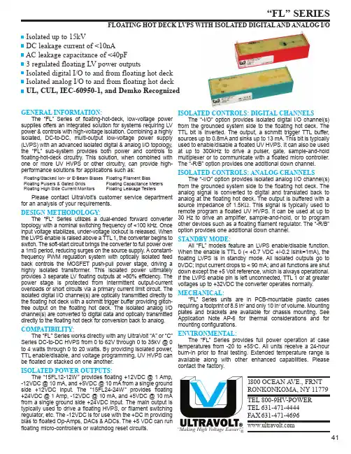
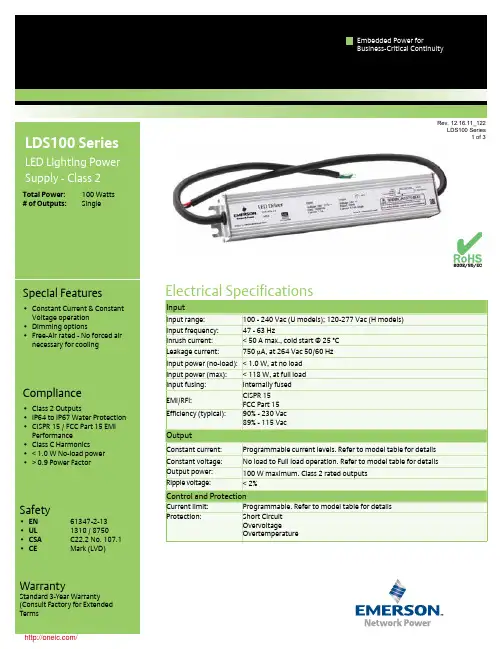
1800 OCEAN A VE., FRNTRONKONKOMA, NY 11779TEL 800-9HV-POWER TEL 631-471-4444FAX 631-471-4696“Making High Voltage Easier!”®Isolated up to 15kVDC leakage current of <10nA AC leakage capacitance of <40pF 3 regulated floating LV power outputsIsolated digital I/O to and from floating hot deck Isolated analog I/O to and from floating hot deck UL, CUL, IEC-60950-1, and Demko RecognizedGENERAL INFORMATION:The “FL” Series of floating-hot-deck, low-voltage power supplies offers an integrated solution for systems requiring LV power & controls with high-voltage isolation. Combining a highly isolated, DC-to-DC, multi-output low-voltage power supply (LVPS) with an advanced isolated digital & analog I/O topology,the “FL” sub-system provides both power and controls to floating-hot-deck circuitry. This solution, when combined with one or more UV HVPS or other circuitry, can provide high-performance solutions for applications such as:Floating/Stacked Ion- or E-Beam Biases Floating Filament Bias Floating Pulsers & Gated Grids Floating Capacitance Meters Floating High Side Current Monitors Floating Leakage TestersPlease contact UltraVolt's customer service department for an analysis of your requirements.DESIGN METHODOLOGY:The “FL” Series utilizes a dual-ended forward converter topology with a nominal switching frequency of <100 kHz. Once input voltage stabilizes, under-voltage lockout is released. When the LVPS enable is raised above a TTL 1, the converter begins to switch. The soft-start circuit brings the converter to full power over a 1mS period, reducing surges on the source supply. A constant-frequency PWM regulation system with optically isolated feed back controls the MOSFET push-pull power stage, driving a highly isolated transformer. This isolated power ultimately provides 3 separate LV floating outputs at >80% efficiency. The power stage is protected from intermittent output-current overloads or short circuits via a primary current limit circuit. The isolated digital I/O channel(s) are optically transmitted directly to the floating hot deck with a schmitt trigger buffer providing glitch-free output on the floating hot deck. The isolated analog I/O channel(s) are converted to digital data and optically transmitted directly to the floating hot deck for conversion back to analog.COMPATIBILITY:The “FL” Series works directly with any UltraVolt “A” or “C”Series DC-to-DC HVPS from 0 to 62V through 0 to 35kV @ 0to 4 watts through 0 to 20 watts. By providing isolated power,TTL enable/disable, and voltage programming, UV HVPS can be floated or stacked on one another.ISOLATED POWER OUTPUTS:The “15FL12-12W” provides floating +12VDC @ 1 Amp, -12VDC @ 10 mA, and +5VDC @ 10 mA from a single ground side +12VDC input. The “15FL24-24W” provides floating +24VDC @ 1 Amp, -12VDC @ 10 mA, and +5VDC @ 10 mA from a single ground side +24VDC input. The main output is typically used to drive a floating HVPS, or filament switching regulator, etc. The -12VDC is for use with the +DC in providing bias to floated Op-Amps, DACs & ADCs. The +5 VDC can run floating micro-controllers or watchdog reset circuits.ISOLATED CONTROLS: DIGITAL CHANNELSThe “-I/O” option provides isolated digital I/O channel(s)from the grounded system side to the floating hot deck. The TTL bit is inverted. The output, a schmitt trigger TTL buffer,sources up to 0.8mA and sinks up to 13 mA. This bit is typically used to enable/disable a floated UV HVPS. It can also be used at up to 300kHz to drive a pulser, gate, sample-and-hold multiplexer or to communicate with a floated micro controller.The “-R/B” option provides one additional down channel.ISOLATED CONTROLS: ANALOG CHANNELSThe “-I/O” option provides isolated analog I/O channel(s)from the grounded system side to the floating hot deck. The analog signal is converted to digital and translated back to analog at the floating hot deck. The output is buffered with a source impedance of 1.5K Ω. This signal is typically used to remote program a floated UV HVPS. It can be used at up to 30 Hz to drive an amplifier, sample-and-hold, or to program other devices such as a floating filament regulator. The “-R/B”option provides one additional down channel.STANDBY MODE:All “FL” models feature an LVPS enable/disable function.When the enable is TTL 0 (< +0.7 VDC +/-0.2 Isink=1mA), the floating LVPS is in standby mode. All isolated outputs go to 0VDC; input current drops to < 90 mA; and all functions are shut down except the +5 Volt reference, which is always operational.If the LVPS enable pin is left unconnected, TTL 1 or at greater voltages up to +32VDC the converter operates normally.MECHANICAL:“FL” Series units are in PCB-mountable plastic cases requiring a footprint of 8.5 in 2and only 10 in 3of volume. Mounting plates and brackets are available for chassis mounting. See Application Note AP-6 for thermal considerations and for mounting configurations.ENVIRONMENTAL:The “FL” Series provides full power operation at case temperatures from -20 to +55o C. All units receive a 24-hour burn-in prior to final testing. Extended temperature range is available along with other enhanced capabilities. Please contact the factory.FLOATING HOT DECK LVPS WITH ISOLATED DIGITAL AND ANALOG I/O41Specifications subject to change without noticeFLOATING HOT DECK LVPS WITH ISOLATED DIGITAL AND ANALOG I/OTEL 800-9HV-POWER or 800-948-7693 or 631-471-4444 FAX 631-471-46961800 Ocean Ave., Frnt, Ronkonkoma, NY 11779“Making High Voltage Easier!”®42TEL 800-9HV-POWER or 800-948-7693 or 631-471-4444 FAX 631-471-46961800 Ocean Ave., Frnt, Ronkonkoma, NY 11779“Making High Voltage Easier!”®FLOATING HOT DECK LVPS WITH ISOLATED DIGITAL AND ANALOG I/O43Ordering Information1 - Input Power Ground Return2 - Positive Power Input3 - LVPS Enable/Disable Input4 - TTL Up/HVPS Enable/Disable (-I/O Only)5 - Signal Ground Return6 - Analog Up/ HVPS Remote Programming Input (-I/O Only)7 - +5V Reference Output1 - Floating +Iout monitor input (Analog Down Channel 1)2 - Floating -Iout monitor input (Analog Down Channel 1)3 - Floating +Eout monitor input (Analog Down Channel 2)4 - Floating -Eout monitor input (Analog Down Channel 2)Local ConnectionsTypeOption Power5 - N/C (reserved for future use)7 - Floating TTL input (Digital Down Channel 1)6 - N/C (reserved for future use)Additional Isolated Connections (-R/B only)Example:15FL12-12W-I/OIsolation Model Input8 - +Iout monitor output (Analog Down Channel 1)9 - -Iout monitor output (Analog Down Channel 1)10- +Eout monitor output (Analog Down Channel 2)11- -Eout monitor output (Analog Down Channel 2)12 - N/C (reserved for future use)13 - N/C (reserved for future use)14 - TTL output (Digital Down Channel 1)Additional Local Connections (-R/B option)8 - Floating PWR Ground Return 9 - Floating +12VDC or +24VDC Output 10 - Floating -12VDC Output11 - Floating TTL Up/HVPS Enable/Disable (-I/O Only)12 - Floating Signal Ground Return13 - Floating Analog Up/ HVPS Remote Programming Input (-I/O Only)14 - Floating +5.6V Reference OutputIsolated/Floating ConnectionsCopyright 1991-2006, UltraVolt, Inc.Rev. G 10/061800 Ocean Ave., Frnt, Ronkonkoma, NY 11779“Making High Voltage Easier!”®44IEC-60950-1All units are RoHS-5 compliant.Models with -RB option are not yet certified withUL, CUL, IEC-60950-1, or Demko.。
nRF24L01+单片机2.4 GHz收发器产品说明书v1.0主要功能:全球通用的2.4 GHz ISM波段操作250kbps, 1Mbps and 2Mbps空中数据传输速率超低功率运行发射功率为0dBm(1.0mW)时,发射电流为11.3mA2Mbps空中数据传输速率,接收电流为13.5mA掉电电流为900nA待机-I电流26μA片内电压调整器1.9至3.6V电源供电范围增强型ShockBurst TM自动数据包处理自动包数据包事务处理6数据通道的MultiCeiver TM与nRF24L01嵌入式兼容空中数据速率250kbps 和1Mbps,与nRF2401A,nRF2402, nRF24E1和nRF24E2兼容低BOM成本±60ppm 16MHz晶振容许5V输入紧凑的20引脚4x4mm QFN封装应用无线 PC外围设备鼠标,键盘和遥控器三和一桌面捆绑先进的媒体中心遥控器网络电话耳机游戏控制器蓝牙模块运动手表和传感器消费电子产品射频遥控器家庭和商业自动化超低功率无线传感器网络RFID 射频识别资产跟踪系统玩具免责条款北欧半导体ASA有权做出随时更改,提高产品可靠性、功能或设计,不另行通知。
北欧半导体ASA不承担由于应用程序或使用任何所述产品或电路引起的责任。
所有应用程序的信息咨询,不构成说明书的组成部分。
极限值超过一个或多个限制的应力可能会造成设备永久性损坏。
这些应力等级只有在这样或那样的操作环境中提出,在规范中没有给出。
长时间暴露在限制值附近可能会影响设备的可靠性。
生命支持应用这些产品并非为因故障会引起人身伤害的维生装备,设备或系统设计的。
北欧半导体ASA客户使用或出售这些产品,他们将自担风险并同意完全赔偿北欧半导体ASA因使用不当或销售行为造成任何损害。
详细联系方式访问www.nordicsemi.no进入北欧半导体销售办事处和全世界的分销商网站总办公室:Otto Nielsens vei 127004 Trondheim电话: +47 72 89 89 00传真: +47 72 89 89 89www.nordicsemi.no写作惯例本产品规范遵循一套排版规则,文档一致,容易阅读。
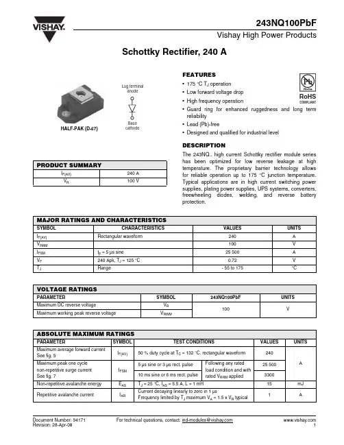
Document Number: 94171For technical questions, contact: ind-modules@Schottky Rectifier, 240 A243NQ100PbFVishay High Power ProductsFEATURES•175 °C T J operation •Low forward voltage drop •High frequency operation•Guard ring for enhanced ruggedness and long term reliability•Lead (Pb)-free•Designed and qualified for industrial levelDESCRIPTIONThe 243NQ.. high current Schottky rectifier module series has been optimized for low reverse leakage at high temperature. The proprietary barrier technology allows for reliable operation up to 175 °C junction temperature.Typical applications are in high current switching power supplies, plating power supplies, UPS systems, converters,freewheeling diodes, welding, and reverse battery protection.PRODUCT SUMMARYI F(AV)240 A V R100 VMAJOR RATINGS AND CHARACTERISTICSSYMBOL CHARACTERISTICSVALUES UNITS I F(AV)Rectangular waveform240A V RRM 100V I FSM t p = 5 µs sine 25 500A V F 240 Apk, T J = 125 °C 0.72V T JRange- 55 to 175°CVOLTAGE RATINGSPARAMETERSYMBOL243NQ100PbFUNITS Maximum DC reverse voltageV R 100VMaximum working peak reverse voltageV RWMABSOLUTE MAXIMUM RATINGSPARAMETER SYMBOL TEST CONDITIONSVALUES UNITSMaximum average forward current See fig. 5I F(AV)50 % duty cycle at T C = 132 °C, rectangular waveform 240A Maximum peak one cycle non-repetitive surge current See fig. 7I FSM 5 µs sine or 3 µs rect. pulseFollowing any rated load condition and with rated V RRM applied25 50010 ms sine or 6 ms rect. pulse 3300Non-repetitive avalanche energy E AS T J = 25 °C, I AS = 5.5 A, L = 1 mH15mJ Repetitive avalanche currentI ARCurrent decaying linearly to zero in 1 µsFrequency limited by T J maximum V A = 1.5 x V R typical1A 元器件交易网 For technical questions, contact: ind-modules@Document Number: 94171243NQ100PbFVishay High Power Products Schottky Rectifier, 240 ANote(1)Pulse width = 500 µsELECTRICAL SPECIFICATIONSPARAMETER SYMBOLTEST CONDITIONSV ALUES UNITSMaximum forward voltage drop See fig. 1V FM (1)240 AT J = 25 °C 0.95V 480 A 1.26240 A T J = 125 °C 0.72480 A0.85Maximum reverse leakage current See fig. 2I RM T J = 25 °C V R = Rated V R6mA T J = 125 °C80Maximum junction capacitance C T V R = 5 V DC (test signal range 100 kHz to 1 MHz) 25 °C 5500pF Typical series inductance L S From top of terminal hole to mounting plane 5.0nH Maximum voltage rate of change dV/dtRated V R10 000V/µs THERMAL - MECHANICAL SPECIFICATIONSPARAMETERSYMBOL TEST CONDITIONSVALUES UNITS Maximum junction and storage temperature range T J , T Stg - 55 to 175°CMaximum thermal resistance,junction to caseR thJC DC operation See fig. 40.19°C/WTypical thermal resistance, case to heatsink R thCSMounting surface, smooth and greased0.05Approximate weight 30g 1.06oz.Mounting torque minimum Non-lubricated threads3 (26.5)N ⋅ m (lbf ⋅ in)maximum 4 (35.4)Terminal torque minimum 3.4 (30)maximum5 (44.2)Case styleHALF-PAK module元器件交易网Document Number: 94171For technical questions, contact: ind-modules@243NQ100PbFSchottky Rectifier, 240 AVishay High Power ProductsFig. 1 - Maximum Forward Voltage Drop CharacteristicsFig. 2 - Typical Values of Reverse Current vs.Reverse VoltageFig. 3 - Typical Junction Capacitance vs. Reverse VoltageFig. 4 - Maximum Thermal Impedance Z thJC Characteristics元器件交易网 For technical questions, contact: ind-modules@Document Number: 94171243NQ100PbFVishay High Power Products Schottky Rectifier, 240 AFig. 5 - Maximum Allowable Case Temperature vs.Average Forward CurrentFig. 7 - Maximum Non-Repetitive Surge CurrentFig. 8 - Unclamped Inductive Test CircuitNote(1)Formula used: T C = T J - (Pd + Pd REV ) x R thJC ;Pd = Forward power loss = I F(AV) x V FM at (I F(AV)/D) (see fig. 6);Pd REV = Inverse power loss = V R1 x I R (1 - D); I R at V R1 = Rated V R元器件交易网元器件交易网Schottky Rectifier, 240 A Vishay High Power ProductsORDERING INFORMATION TABLELINKS TO RELATED DOCUMENTSDimensions /doc?95020Document Number: 94171For technical questions, contact: ind-modules@ Disclaimer Legal Disclaimer NoticeVishayAll product specifications and data are subject to change without notice.Vishay Intertechnology, Inc., its affiliates, agents, and employees, and all persons acting on its or their behalf (collectively, “Vishay”), disclaim any and all liability for any errors, inaccuracies or incompleteness contained herein or in any other disclosure relating to any product.Vishay disclaims any and all liability arising out of the use or application of any product described herein or of any information provided herein to the maximum extent permitted by law. The product specifications do not expand or otherwise modify Vishay’s terms and conditions of purchase, including but not limited to the warranty expressed therein, which apply to these products.No license, express or implied, by estoppel or otherwise, to any intellectual property rights is granted by this document or by any conduct of Vishay.The products shown herein are not designed for use in medical, life-saving, or life-sustaining applications unless otherwise expressly indicated. Customers using or selling Vishay products not expressly indicated for use in such applications do so entirely at their own risk and agree to fully indemnify Vishay for any damages arising or resulting from such use or sale. Please contact authorized Vishay personnel to obtain written terms and conditions regarding products designed for such applications.Product names and markings noted herein may be trademarks of their respective owners.元器件交易网Document Number: 。
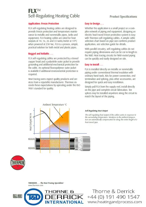
FLX TMSelf-Regulating Heating CableProduct SpecificationsApplication: Freeze ProtectionFLX self-regulating heating cables are designed to provide freeze protection and temperature mainte-nance to metallic and nonmetallic pipes, tanks and equipment. FLX heating cables are rated for heat outputs of 10, 16, 26 and 33 watts/meter at 10°C when powered at 230 Vac. FLX is a proven, simple, practical solution for both metal and plastic pipes.Rugged and Reliable . . .FLX self-regulating cables are protected by a tinned copper braid and a polyolefin outer jacket to provide grounding and additional mechanical protection for the cable. An optional fluoropolymer outer jacket is available if additional environmental protection is required.Heat tracing users expect quality products and ser-vices from a reputable manufacturer. Thermon ex-ceeds these expectations by operating under the ISO 9001 standard for quality.THERMON . . . The Heat Tracing Specialists ®Easy to Design . . .Whether the application is a small project or a com-plex network of piping and equipment, designing an electric heat traced freeze protection system is easy with Thermon self-regulating cables. A simple cable selection chart based on pipe size confirms product application; see selection guide for details.With parallel circuitry, self-regulating cables do not require piping dimensions and can be cut to length in the field. Heat tracing circuits for field-routed piping can be quickly and easily designed on site.Easy to Install . . .FLX is installed directly on metallic or nonmetallic piping under conventional thermal insulation with ordinary hand tools. Kits for power connection, end termination and splicing, plus other accessories, are designed for quick and easy installation.Simply pull FLX from the supply reel, install directly on the pipe and complete circuit fabrication. Teesplices may be installed anywhere along the circuit to match the layout of the piping.Corporate Headquarters100 Thermon Dr. •PO Box 609San Marcos, TX 78667-0609 •USA Phone: +1 512-396-5801European HeadquartersBoezemweg 25 •PO Box 2052640 AE Pijnacker •The Netherlands Phone: +31 (0) 15-36 15 370For the Thermon office nearest youvisit us at . . FLX TMSelf-Regulating Heating CableProduct SpecificationsCircuit Breaker Sizing and Type . . .Power Output Curves . . .Pipe Temperature °CW a t t s p e r M e t e r2530020405003020351015105FLX at 230 Vac60Form CPD1007U-0307 © Thermon Manufacturing Co. Specifications are subject to change without notice.40Characteristics . . . Nominal Outside Dimension . . .No. 2043400Certifications/Approvals . . .Bus wire ................................................................................................................................................1,3 mm nickel-plated copper Metallic braid ................................................................................................................................................................tinned copper Outer jacket ...............................................................................................................................-OJ, polyolefin; -FOJ, fluoropolymer Minimum bend radius @ -15°C ..........................................................................................................................................................................10 mm @ -60°C ..........................................................................................................................................................................32 mm Supply voltage .......................................................................................................................................................................230 Vac Circuit protection .................................................................................................................30 mA ground-fault protection required Maximum continuous exposure temperature ...............................................................................power-on: 65°C; power-off: 85°C。
水体示踪荧光仪fl24 原理下载温馨提示:该文档是我店铺精心编制而成,希望大家下载以后,能够帮助大家解决实际的问题。
文档下载后可定制随意修改,请根据实际需要进行相应的调整和使用,谢谢!并且,本店铺为大家提供各种各样类型的实用资料,如教育随笔、日记赏析、句子摘抄、古诗大全、经典美文、话题作文、工作总结、词语解析、文案摘录、其他资料等等,如想了解不同资料格式和写法,敬请关注!Download tips: This document is carefully compiled by the editor. I hope that after you download them, they can help yousolve practical problems. The document can be customized and modified after downloading, please adjust and use it according to actual needs, thank you!In addition, our shop provides you with various types of practical materials, such as educational essays, diary appreciation, sentence excerpts, ancient poems, classic articles, topic composition, work summary, word parsing, copy excerpts,other materials and so on, want to know different data formats and writing methods, please pay attention!水体示踪荧光仪fl24是一种用于检测水体中微量有机物质的仪器,其原理主要基于有机物质在紫外光的作用下产生荧光信号的特性。
Designation:F2413–05Standard Specification forPerformance Requirements for Foot Protection1This standard is issued under thefixed designation F2413;the number immediately following the designation indicates the year of original adoption or,in the case of revision,the year of last revision.A number in parentheses indicates the year of last reapproval.A superscript epsilon(e)indicates an editorial change since the last revision or reapproval.INTRODUCTIONFor more than sixty years,the predecessor to this specification,ANSI Z41,established the performance criteria for a wide range of footwear to protect from hazards that affect the personal safety of workers.The value of these standards was recognized early in the history of Occupational Safety and Health Administration(OSHA)and incorporated as a reference standard in the Code of Federal Regulations (CFR)1910.The specification contains performance requirements for footwear to protect workers’feet from the following hazards by providing:(1)impact resistance for the toe area of footwear;(2)compression resistance for the toe area of the footwear;(3)metatarsal impact protection that reduces the chance of injury to the metatarsal bones at the top of the foot;(4)conductive properties which reduce hazards that may result from static electricity buildup;and reduce the possibility of ignition of explosives and volatile chemicals;(5)electric shock resistance,to protect the wearer when accidental contact is made with live electric wires;(6)static dissipative(SD)properties to reduce hazards due to excessively low footwear resistance that may exist where SD footwear is required;(7)puncture resistance of footwear bottoms;(8)chain saw cut resistance;and(9)dielectric insulation.1.Scope1.1This specification covers minimum requirements for the design,performance,testing,and classification of footwear designed to provide protection against a variety of workplace hazards that can potentially result in injury.1.2The objective of this specification is to prescribefit, function,and performance criteria for footwear that is intended to be worn to reduce injuries.1.3This specification is not intended to serve as a detailed manufacturing or purchasing specification,but can be refer-enced in purchase contracts to ensure that minimum perfor-mance requirements are met.1.4Controlled laboratory tests used to determine compli-ance with the performance requirements of this specification shall not be deemed as establishing performance levels for all situations to which individuals may be exposed.1.5The values stated in SI units are to be regarded as the standard.The values given in parentheses are for information only.1.6This standard does not purport to address all of the safety concerns,if any,associated with its use.It is the responsibility of the user of this standard to establish appro-priate safety and health practices and determine the applica-bility of regulatory limitations prior to use.2.Referenced Documents2.1ASTM Standards:2B117Practice for Operating Salt Spray(Fog)Apparatus F1116Test Method for Determining Dielectric Strength of Dielectric FootwearF1117Specification for Dielectric FootwearF1818Specification for Foot Protection for Chainsaw Us-ersF2412Test Methods for Foot Protection2.2Federal Standards:3CFR1910.132Personal Protective Equipment–General Re-quirementsCFR1910.136Personal Protective Equipment–Occupa-tional Foot Protection1This specification is under the jurisdiction of ASTM Committee F13on Pedestrian/Walkway Safety and Footwear and is the direct responsibility of Subcommittee F13.30on Footwear.Current edition approved March1,2005.Published March2005.2For referenced ASTM standards,visit the ASTM website,,or contact ASTM Customer Service at service@.For Annual Book of ASTM Standards volume information,refer to the standard’s Document Summary page on the ASTM website.3Available from ernment Printing Office Superintendent of Documents, 732N.Capitol St.,NW,Mail Stop:SDE,Washington,DC20401.Copyright©ASTM International,100Barr Harbor Drive,PO Box C700,West Conshohocken,PA19428-2959,United States.2.3Canadian Standards Association Standard:4CAN/CSA Z195Protective Footwear3.Terminology 3.1Definitions:3.1.1footwear ,n —wearing apparel for the feet (such as shoes,boots,slippers,or overshoes)excluding hosiery.3.1.1.1Discussion —This term can refer to either left foot or right foot units or pairs.3.1.2insert ,n —footbed normally made of a foam product with leather or fabric cover shaped to cover the entire insole which can be inserted between the foot and insole board.3.1.3insole ,n —foundation of the shoe;the inner sole of the shoe which is next to the foot,under the sock liner or the insert,onto which the upper is lasted.3.1.4last ,n —solid hinged form,in the general shape of a foot,around which footwear is constructed.3.1.5lasting ,v —building of footwear around a specific foot form.3.1.6lining ,n —term used to describe all components that can be used to construct the interior of the upper part of the footwear.3.1.7outsole and heel ,n —exterior bottom platform of the footwear;the bottom surface.3.1.8product category ,n —description for a type of foot-wear designed and manufactured for a specific hazard or hazards.3.1.9product classification ,n —footwear manufactured to meet a minimum performance requirement for a specific hazard or hazards.3.1.10protective footwear ,n —footwear that is designed,constructed,and classified to protect the wearer from a potential hazard or hazards.3.1.11protective toe cap ,n —component designed to pro-vide toe protection that is an integral and permanent part of the footwear.3.1.12quarter ,n —entire back portion of the footwear upper.3.1.13shall ,v —mandatory action.3.1.14should ,v —advisory comment.3.1.15size ,n —length and breadth measurements of foot-wear determined by using a specific grading;the American system of footwear grading.3.1.16socklining ,n —material placed over the insole which is imprinted with a brand name or other designation.3.1.17upper ,n —parts of a shoe or boot that are above the sole.4.Significance and Use4.1This specification contains requirements to evaluate the performance of footwear for the following:4.1.1Impact resistance for the toe area of footwear,4.1.2Compression resistance for the toe area of footwear,4.1.3Metatarsal protection that reduces the chance of injury to the metatarsal bones at the top of the foot,4.1.4Conductive properties which reduce hazards that may result from static electricity buildup,and reduce the possibility of ignition of explosives and volatile chemicals,4.1.5Electric shock resistance,4.1.6Static dissipative (SD)properties to reduce hazards due to excessively low footwear resistance that may exist where SD footwear is required,4.1.7Puncture resistance of footwear bottoms,4.1.8Chain saw cut resistance,and 4.1.9Dielectric insulation.5.Performance Requirements and Workmanship 5.1Impact Resistant Footwear :5.1.1Impact resistant footwear shall also meet the require-ments of 5.2for compression resistant footwear.5.1.2Footwear shall be designed,constructed,and manu-factured so that a protective toe cap is an integral and permanent part of the footwear.5.1.3The workmanship in the production and assembly of the footwear shall ensure that the footwear provides function-ality to the wearer.5.1.4Classification shall be determined by evaluating three specimens in accordance with Test Methods F 2412.The product classification for impact resistance represents the minimum force required for each classification that results in the toe area of the footwear having a minimum interior height clearance of 12.7mm (0.50in.)in men’s footwear and 11.9mm (0.468in.)in women’s footwear.5.1.4.1Impact resistance of footwear shall be classified as follows:(1)Class 75product classification men’s footwear shall demonstrate a minimum interior height clearance of 12.7mm (0.50in.)during exposure to impact energy of 101.7J (75ft-lbf).(2)Class 75product classification women’s footwear shall demonstrate a minimum interior height clearance of 11.9mm (0.468in.)during exposure to impact energy of 101.7J (75ft-lbf).(3)Class 50product classification men’s footwear shall demonstrate a minimum interior height clearance of 12.7mm (0.50in.)during exposure to impact energy of 67.8J (50ft-lbf).(4)Class 50product classification women’s footwear shall demonstrate a minimum interior height clearance of 11.9mm (0.468in.)during exposure to impact energy of 67.8J (50ft-lbf).5.1.4.2Any specimen that does not meet the minimum impact performance requirements for the product classification constitutes failure for the product category.5.1.4.3Protective toe footwear specimens or samples shall be retested for classification for any of the following changes:(1)Change in material used to make protective toe cap,change in protective cap manufacturer,or changes in the design of the toe cap.(2)Change in construction method used to make footwear.(3)Change in the upper or insole material thickness greater than 25%,change to the soling system,or a change in the hardness of the outsole.(4)Shape of last used in the manufacturing of footwear.4Available from Canadian Standards Association (CSA),178Rexdale Blvd.,Toronto,ON CanadaM9W1R3.5.2Compression Resistant Footwear:5.2.1Compression resistant footwear shall also meet the requirements of5.1for impact resistant footwear.5.2.2Footwear shall be designed,constructed,and manu-factured so that a protective toe cap is an integral and permanent part of the footwear.5.2.3The workmanship in the production and assembly of the footwear shall ensure that the footwear provides function-ality to the wearer.5.2.4Classification shall be determined by evaluating three specimens in accordance with Test Methods F2412.The product classification for compression resistance represents the minimum force required that results in the toe area of the footwear having a minimum interior height clearance of12.7 mm(0.50in.)in men’s footwear and11.9mm(0.468in.)in women’s footwear.5.2.4.1Compression resistance of footwear shall be classi-fied as follows:(1)Class75product classification men’s footwear shall demonstrate a minimum interior height clearance of12.7mm (0.50in.)during exposure to a compressive force of11121N (2500lbf).(2)Class75product classification women’s footwear shall demonstrate a minimum interior height clearance of11.9mm (0.468in.)during exposure to a compressive force of11121N (2500lbf).(3)Class50product classification men’s footwear shall demonstrate a minimum interior height clearance of12.7mm (0.50in.)during exposure to a compressive force of7784N (1750lbf).(4)Class50product classification women’s footwear shall demonstrate a minimum interior height clearance of11.9mm (0.468in.)during exposure to a compressive force of7784N (1750lbf).5.2.4.2Any specimen that does not meet the minimum compression resistance requirements for the product classifi-cation constitutes a failure for the product category.5.2.4.3Compression resistant footwear shall be retested for classification for any of the following changes:(1)Change in material to make protective toe cap,change in protective toe cap manufacturer,or changes in the design of the toe cap.(2)Change in construction method used to make footwear.(3)Change in the upper or insole material thickness greater than25%,change to the soling system,or a change in the hardness of the outsole.(4)Shape of last used in manufacturing of footwear.5.2.4.4Classifications—Protective footwear shall be classi-fied in accordance with the tables below for its ability to meet compression resistance and impact resistance.The proper classification shall be determined by the test results of three specimens for each requirement.5.2.4.5The lowest recorded compression or impact resis-tance of the three test specimens will determine the footwear classification.If the product fails to meet the class for which it is intended,you must retest.For example,if a product test results meet Class50for compression resistance and Class75 for impact resistance,the rating of the footwear will be I50/C50.Classification Table ImpactI/75=75ft-lbs(101.7J)I/50=50ft-lbs(67.8J)Classification Table CompressionC/75=2500lb(11121N)C/=1750lb(7784N)Minimum Clearance(all classifications)Men=0.500in.(12.7mm)Women=0.468in.(11.9mm)5.3Metatarsal Protective Footwear:5.3.1Metatarsal protective footwear shallfirst meet the requirements of5.1for impact resistant footwear and5.2for compression resistant footwear.5.3.2Footwear shall be designed,constructed,and manu-factured so that a metatarsal impact guard is positioned partially over the protective toe cap and extended to cover the metatarsal bone area.The metatarsal protection shall be an integral and permanent part of the footwear.5.3.3The workmanship in the production and assembly of the footwear shall ensure that the footwear provides function-ality to the wearer.5.3.4Classification shall be determined by evaluating three specimens in accordance with Test Methods F2412.The product classification for metatarsal protection shall be made after the footwear has been classified for impact resistance and compression resistance.5.3.4.1Class75product classification metatarsal protective footwear for men shallfirst meet the performance requirements for Class75Impact Resistant and Class75Compression Resistant footwear.Subsequent to meeting these performance requirements,the height of the wax form used to measure metatarsal protection shall be a minimum of25.4mm(1.0in.) after exposure of impact energy of101.7J(75ft-lbf).5.3.4.2Class75product classification metatarsal protective footwear for women shallfirst meet the performance require-ments for Class75Impact Resistant and Class75Compression Resistant footwear.Subsequent to meeting these performance requirements,the height of the wax form used to measure metatarsal protection shall be a minimum of23.8mm(0.937 in.)after exposure of impact energy of101.7J(75ft-lbf). 5.3.4.3Class50product classification metatarsal protective footwear for men shallfirst meet the performance requirements for Class50Impact Resistant and Class50Compression Resistant footwear.Subsequent to meeting these performance requirements,the height of the wax form used to measure metatarsal protection shall be a minimum of25.4mm(1.0in.) after exposure of impact energy of67.8J(50ft-lbf).5.3.4.4Class50product classification metatarsal protective footwear for women shallfirst meet the performance require-ments for Class50Impact Resistant and Class50Compression Resistant footwear.Subsequent to meeting these performance requirements,the height of the wax form used to measure metatarsal protection shall be a minimum of23.8mm(0.937 in.)after exposure of impact energy of67.8J(50ft-lbf).5.3.4.5Any specimen that does not meet the metatarsal impact resistance performance requirement constitutes a failure for the product category.5.3.4.6Metatarsal impact resistance protection shall be retested for classification for any of the following changes:(1)Change in material used to produce the metatarsal impact resistant protection device,change in manufacturer,or design of the product,or a combination thereof.(2)Change in construction method used to make footwear.(3)Change in the upper or insole material thickness greater than25%,a change to the soling system,or a change in the hardness of the outsole.(4)Shape of last used in manufacturing of footwear.5.4Conductive Protective Footwear:5.4.1Conductive footwear shall also meet the requirements of5.1for impact resistant footwear and5.2for compression resistant footwear.5.4.2Footwear shall be designed,constructed,and manu-factured to provide protection for the wearer against hazards that may result from static electricity buildup and to reduce the possibility of ignition of explosives or volatile chemicals. 5.4.2.1Footwear shall dissipate static electricity from the body to reduce the possibility of ignition of volatile com-pounds.5.4.2.2Footwear shall be of a construction that facilitates a stable electrically conductive path.All external components shall be made of nonferrous materials.5.4.2.3Conductive footwear is not designed to be worn by personnel working near open electrical circuits.5.4.3The workmanship in the production and assembly of the footwear shall ensure that the footwear provides function-ality to the wearer.5.4.3.1The uppers shall be made of materials that facilitate the dissipation of static electricity.5.4.3.2The insoles,linings,outsoles,and heels of the footwear shall be made of any combination of materials and compounds which will facilitate electrical conductivity and the transfer of static electricity build up from the body to the ground.5.4.3.3The recommended design of the outsole and heel isa single unit.Where the outsole and heel are separate compo-nents,the following practices shall be used.(1)Heel shall be attached to outsole to ensure no disruption in electrical conductivity.(2)Non-ferrous heel nails shall be used to attach the heels when heel nails are used.These nails shall be recessed within the tread surface and then covered with conductive material. These nails shall not be either exposed or visible.5.4.4Electrical resistance shall be determined by evaluating the minimum number of specimens per lot size in accordance with Test Methods F2412.5.4.4.1The specimens shall demonstrate resistance between 0to500000ohms.5.4.4.2Any specimen or sample of conductive footwear that does not meet the performance requirement constitutes a failure for the lot.5.5Electric Shock Resistant Footwear:5.5.1Electric shock resistant footwear shall also meet the requirements of5.1for impact resistant footwear and5.2for compression resistant footwear.5.5.2Electric shock resistant footwear shall be designed, constructed,and manufactured with non-conductive electric shock resistant soles and heels so that the footwear outsole can provide a secondary source of electric shock resistance protec-tion to the wearer against the hazards from an incidental contact with live electrical circuits,electrically energized conductors,parts,or apparatus.5.5.3Footwear shall have an electrical shock resistant outsole and heel with an outer surface which is not penetrated by electrically conductive components,parts,or conductive materials.5.5.4Footwear outsole shall provide a secondary source of protection against incidental contact with live electrical cir-cuits,electrically energized conductors,parts,or apparatus under dry conditions.5.5.5Electrical hazard protection is severely deteriorated in the following conditions:excessive wear on the outsole and heel or exposure to wet and humid environments,or both. 5.5.6The workmanship in the production and assembly of the footwear shall ensure that the footwear provides function-ality to the wearer.5.5.7The outsoles and heels shall be made of materials designed to offer electrical insulative properties to provide electric shock resistance.5.5.8Electric shock resistance of the footwear shall be determined by evaluating the minimum number of specimens per lot size in accordance with Test Methods F2412.5.5.8.1Protective footwear constructed or manufactured to be electrically shock resistant shall be capable of withstanding the application of14000V(root mean square(rms))at60Hz for1min with no currentflow or leakage current in excess of 3.0mA under dry conditions.5.5.9Any specimen that does not meet the performance requirement constitutes a failure for the lot.5.6Static Dissipative(SD)Footwear:5.6.1Static dissipative footwear shall also meet the require-ments of5.1for impact resistant footwear and5.2for com-pression resistant footwear.5.6.2Static dissipative footwear shall be designed,con-structed,and manufactured to provide protection to the wearer against hazards which may exist due to excessively low footwear resistance in a work environment,as well as maintain a sufficiently high level of resistance to reduce the possibility of electrical shock in work areas where SD footwear is worn.5.6.2.1Footwear shall reduce the excess static electricity by conducting the charge(from body)to ground while simulta-neously maintaining a sufficiently high level of resistance(106 ohms)(1megohm)to protect the wearer when exposed to hazards from incidental contact with live electric circuits.5.6.2.2Using human subjects,a pair of footwear shall havea lower limit of electrical resistance of106ohms(1megohm) and have an upper limit electrical resistance of108ohms(100megohms).5.6.3The workmanship in the production and assembly of the footwear shall ensure that the footwear provides function-ality to the wearer.5.6.3.1The footwear shall use any combination of materials that facilitate static dissipation by a consistent path of resis-tance.5.6.3.2The inconsistency of certain hygroscopic materials can result in footwear not being able to consistently meet the performance requirements of static dissipative footwear.5.6.3.3Heels shall be attached using non-ferrous heel nails. These nails shall be recessed within the tread surface and then covered with conductive material.These nails shall be neither exposed nor visible.5.6.4Static dissipation shall be determined by evaluating the minimum number of specimens per lot size in accordance with Test Methods F2412.5.6.4.1Any specimen that does not meet the performance requirement constitutes a failure for the lot.5.7Puncture Resistant Footwear:5.7.1Puncture resistant footwear shall also meet the re-quirements of5.1for impact resistant footwear and5.2for compression resistant footwear.5.7.2Footwear shall be designed,constructed,and manu-factured so that a puncture resistant plate is positioned between the insole and outsole and is made an integral and permanent part of the footwear.5.7.2.1The puncture resistant components shall reduce the possibility of injury caused by sharp objects that can penetrate the bottom assembly of the footwear.5.7.3The workmanship in the production and assembly of the footwear shall ensure that the footwear provides function-ality to the wearer.5.7.3.1The puncture resistant device shall cover the maxi-mum area of the insole to include as much of the heel area that is allowed by the construction of the footwear and be an integral part of the footwear.5.7.3.2The preferred design of the puncture resistant device is a single unit.5.7.4Puncture resistance shall be determined by evaluating the minimum number of specimens per lot size in accordance with Test Methods F2412.5.7.4.1The specimens shall demonstrate a minimum punc-ture resistance on each device of1200N(270lbf).5.7.5Measureflex resistance to cracking using CAN/CSA Z195.5.7.5.1Puncture resistant devices shall show no signs of cracking after1.5millionflexes.5.7.6Puncture resistant devices shall show no sign of corrosion after being exposed to a5%salt solution for24h,in accordance with B117.5.7.7Each pair of puncture resistant protective devices shall bear the manufacturer’s name,trademark or logo,or both,and month and year of manufacture.This information shall be permanently stamped or marked in a conspicuous location.5.7.8Any specimen that does not meet the performance requirements constitutes a failure for the lot.5.8Chain Saw Cut Resistant Footwear:5.8.1Footwear shall be designed,constructed,and manu-factured so that it can provide protection to the wearer’s feet against the hazards which may result when operating a chain saw.5.8.1.1Chain saw cut resistant footwear is intended to protect the foot area between the toe and lower leg when operating a chain saw.5.8.2The workmanship in the production and assembly of the footwear shall ensure that the footwear provides function-ality to the wearer.These practices shall also meet the requirements of the section on Materials and Workmanship of Specification F1818.5.8.2.1The area of protection shall meet the requirements as stipulated in the section on Areas of Protection of Specification F1818.5.8.3Chain saw cut resistant footwear shall meet the performance requirements of the section on Inspection and Performance Testing of Specification F1818.5.8.3.1Any specimen that does not meet the performance requirements constitutes a failure for the product category. 5.9Dielectric Insulation:5.9.1Footwear shall be designed,constructed,and manu-factured so that it can provide additional insulation if acciden-tal contact is made with energized electrical conductors, apparatus,or circuits.5.9.2Dielectric insulation shall meet the minimum insula-tion performance requirements of the section on Electrical Requirements of Specification F1117as tested in accordance with Test Method F1116.5.9.3Any specimen that does not meet the performance requirements constitutes a failure for the product category.6.Hazard Assessment6.1In conjunction with the advisory in CFR1910.132and CFR1910.136,the user of this specification should conduct a hazard assessment to determine the specific requirements that are needed for the protective footwear to be worn for each specific work place hazard.6.2The classification system and minimum performance requirements for each hazard provide for a zero negative tolerance.Consequently,the assessment and determination of the specific hazards allows for choosing the specific combina-tion of features that the footwear must demonstrate.For example:6.2.1One group of workers in a facility would need footwear that is:Class75Impact ResistantClass75Compression ResistantElectric Shock Resistant6.2.2Another group of workers in the same facility would need footwear that is:Class50Impact ResistantClass50Compression ResistantClass50Metatarsal Impact ResistantElectric Shock Resistantbeling and Identification7.1Labeling and identification of protective footwear is essential to ensure the wearer that footwear meets the required minimum performance(see Table1).7.1.1The label uses a specific four line format that identifies the type of footwear and the hazards for which it is designed to provide protection.7.1.2Print size on labels shall be clearly visual to the eye and shall measure 3.75mm (0.125in.)or larger.7.1.3Line 1—Identifies that the footwear is protective footwear that complies to an ASTM standard with a specific year of issuance.For example:ASTM F 241305(ASTM Standard No.)(Year of issuance)7.1.4Line 2—Identifies the gender of user and the classifi-cations for impact resistance,compression resistance,and metatarsal impact resistance.For example:M/I/75/C/75M I 75C 75MaleImpact Resistant Footwear Impact Classification Compression ResistantFootwear Compression ClassificationF/I/75/C/75F I 75C 75FemaleImpact Resistant FootwearImpact Classification Compression ResistantFootwearCompression ClassificationM/I/50/C/50/Mt/50M I 50C 50MT 50Male Impact Resistant Footwear Impact Classifi-cation Compres-sion Resistant Footwear Compres-sion Classifi-cationMetatarsal Resistant FootwearMetatarsalClassification 7.1.5Lines 3and 4—Identifies footwear made to offer protection from specific types of hazards.Section reference shall be in numerical order.7.1.5.1CD —Identifies protection against conductive haz-ards as discussed in 5.4.7.1.5.2EH —Identifies footwear with outsole and heel made of electrical insulation properties;shock resistant as discussed in 5.5.7.1.5.3SD —Identifies footwear designed to reduce the accumulation of excess static electricity as discussed in 5.6.7.1.5.4PR —Identifies footwear designed to be puncture resistant as discussed in 5.7.7.1.5.5Mt —Identifies footwear designed to be impact re-sistant to the top of the foot as discussed in 5.3.7.1.5.6CS —Identifies footwear which provides chain saw cut resistance as noted in 5.8.7.1.5.7DI —Identifies footwear which provides dielectric insulation as noted in 5.9.7.1.6Line 4—Shall only be used when more than three sections of this specification apply to any one pair of protective footwear.8.Marking and Compliance Requirements8.1The marking as defined in this specification indicates that the protective footwear bearing this label meets the minimum requirements for the product category as defined within this specification.8.2Responsibility of the Manufacturer or Supplier —The manufacturer or supplier,or both,of the protective footwear bearing the marking shall maintain documentation to identify the product category sampled for testing,a report of tests performed,test results date of testing and identify of the independent testing facility used.8.3Compliance Requirements —The manufacturer or sup-plier,or both,of protective footwear bearing the marking label that is found to be in non-compliance with the requirements of this specification is liable for immediate disqualification from using the ASTM label for that product category.8.4The identification of all protective footwear as meeting the requirements of this specification shall follow a consistent pattern.One-half pair shall be clearly and legibly identified in letters and numbers not less than 0.125in.(3.175mm)high.The identification shall be either a stitched in,stamped,or pressure-sensitive label,or a combination thereof.The identi-fication shall be enclosed in a border and be placed on either the surface of the tongue,gusset,shaft,or quarter lining.9.Keywords9.1chain saw protection;conductive footwear;dielectric;electric shock resistance (EH);foot protection;impact resis-tance;metatarsal protection;protective footwear;puncture resistance;safety footwear electrical hazard;static dissipative (ESD)TABLE 1Examples of Marking and IdentificationIdentificationDescriptionExample ALine 1ASTMF 2413–05Protective footwear which complies to the performance requirement of F 2413issued in 2005.Line 2F/I/75/C/75/Mt75Footwear worn by female worker which has Class 75impact resistance;Class 75compression resistance,and Class 75metatarsal impact resistance.Line 3EHThe outsole and heel of this footwear is made with non-conductive materials,shock resistant.Example BLine 1ASTMF 2413–05Protective footwear which complies to the performance requirement of F 2413issued in 2005.Line 2M/I/50/C/50Footwear worn by male worker which has Class 50impact resistance and Class 50compression resistance.Line 3PR Puncture resistant footwearLine 4CSFootwear which is chain saw cut resistant.Example CLine 1ASTMF 2413–05Protective footwear which complies to the performance requirement of F 2413issued in 2005.Line 2M/I/75/C/75Footwear worn by male worker which has a Class 75impact resistance and a Class 75compression resistance.Line 3CDFootwear isconductive.。
专业从事单轴及多轴直线模组滑台、运动控制器的研发、生产、销售服务。
specializing in the development, production, and sales of single-axisand multi-axis linear module, motion controllers industrial equipment.LINEAR MOTION SYSTEM INTELLIGENTPRODUCTS MANUFACTURER3.0LTD 关于我们/ABOUT US P01-08公司简介研发技术生产工艺品质检验客户与案例公司资质产品概述产品详情/PRODUCT DESCRIPTION P09-89 FSK模组FSL系列模组FBL系列模组FPB系列模组FTH系列模组FTB系列模组二轴直角坐标机器人三轴直角坐标机器人定制工作台控制器配件选型我们的服务/OUR SERVICE P90-92售前技术售后服务FUYU TECHNOLOGY CO.,成都福誉科技有限公司成立于2011年11月,专注于直线运动系统的研发、生产、销售和服务。
“福誉科技”不断吸引高端人才,完善产业链集群,同时高度重视与高校、科研院所的产学研结合模式及国内外有实力企业的合作。
“福誉科技”已获国家相关部门认证:“国家高新技术企业”,“双软企业”,ISO9001-2015,知识产权管理体系,知识产权已授权82项,涉及发明专利6项,实用新型、外观专利及软件著作权76项;已获国际相关认证:德国莱茵机构“TUV”认证,及CE, ROHS FCC Ip等级认证。
福誉产品已辐射全球90余个国家,福誉人秉持“真实、担当、持续精进”的价值观,不断迭代优化产品和服务获取与更多合作伙伴的共赢。
Chengdu Fuyu Technology Co., Ltd. was established in November 2011, focusing on the research and development, production, sales and service of linear motion systems. We continue to introduce high-end talents and improve the industrial chain cluster. At the same time, we attach great importance to the mode of production-university- research cooperation with universities and research institutes, and sincerely cooperate with domestic and foreign powerful brand enterprises.FUYU Technology has been certified by relevant national departments: "National High-tech Enterprise", "Double Soft Enterprise", ISO9001-2015, Intellectual Property Management System, 82 intellectual property rights have been authorized, involving 6 invention patents, utility model, appearance patents and 76 software copyrights; The products also have obtained international certifications, such as German Rheinland organization "TUV" and CE, ROHS, FCC, IP66, etc.Fuyu's products have been sold to more than 90 countries around the world, we uphold the values of "Authentic, Responsible and Keep Improving", constantly iteratively optimize products and services to get win-win opportunities with more partners.国家高新技术企业双软企业National High-Tech Enterprise D o u b l e S o f t E n t e r p r i s e专利认证patent certificates一带一路重点推荐企业One Belt One Road Highly Recommeded Enterprise智造商industry qualification certificationsaccumulated coverage companies知识产权82项资质认证19项产品辐射国家地区96个累计客户资源12K个intellectual property rights年均增长幅度146cover 96 countries and regionsSales growth位于成都的福誉科技研发中心,从设备的结构有限元分析,材料分析到加工工艺、装配技术、检测方式、智能软件、底层算法等。