ppt4040
- 格式:ppt
- 大小:571.00 KB
- 文档页数:4


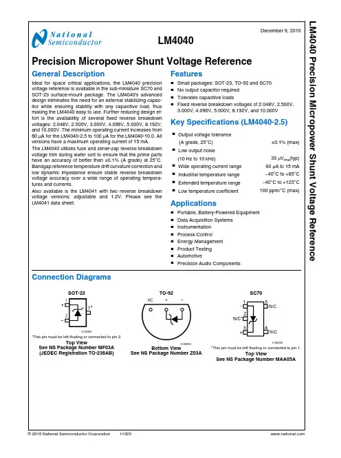
LM4040December 9, 2010 Precision Micropower Shunt Voltage ReferenceGeneral DescriptionIdeal for space critical applications, the LM4040 precision voltage reference is available in the sub-miniature SC70 and SOT-23 surface-mount package. The LM4040's advanced design eliminates the need for an external stabilizing capac-itor while ensuring stability with any capacitive load, thus making the LM4040 easy to use. Further reducing design ef-fort is the availability of several fixed reverse breakdown voltages: 2.048V, 2.500V, 3.000V, 4.096V, 5.000V, 8.192V, and 10.000V. The minimum operating current increases from 60 μA for the LM4040-2.5 to 100 μA for the LM4040-10.0. All versions have a maximum operating current of 15 mA.The LM4040 utilizes fuse and zener-zap reverse breakdown voltage trim during wafer sort to ensure that the prime parts have an accuracy of better than ±0.1% (A grade) at 25°C. Bandgap reference temperature drift curvature correction and low dynamic impedance ensure stable reverse breakdown voltage accuracy over a wide range of operating tempera-tures and currents.Also available is the LM4041 with two reverse breakdown voltage versions: adjustable and 1.2V. Please see the LM4041 data sheet.Features■Small packages: SOT-23, TO-92 and SC70■No output capacitor required■Tolerates capacitive loads■Fixed reverse breakdown voltages of 2.048V, 2.500V,3.000V,4.096V,5.000V, 8.192V, and 10.000VKey Specifications (LM4040-2.5)■ Output voltage tolerance (A grade, 25°C)±0.1% (max)■ Low output noise (10 Hz to 10 kHz)35 μV rms(typ)■ Wide operating current range60 μA to 15 mA ■ Industrial temperature range−40°C to +85°C ■ Extended temperature range−40°C to +125°C ■ Low temperature coefficient100 ppm/°C (max) Applications■Portable, Battery-Powered Equipment■Data Acquisition Systems■Instrumentation■Process Control■Energy Management■Product Testing■Automotive■Precision Audio ComponentsConnection DiagramsSOT-231132301*This pin must be left floating or connected to pin 2.Top ViewSee NS Package Number MF03A(JEDEC Registration TO-236AB)TO-921132303Bottom ViewSee NS Package Number Z03ASC701132330*This pin must be left floating or connected to pin 1.Top ViewSee NS Package Number MAA05A© 2010 National Semiconductor LM4040 Precision Micropower Shunt Voltage ReferenceOrdering InformationIndustrial Temperature Range (−40°C to +85°C)Reverse Breakdown VoltageTolerance at 25°C and AverageReverseBreakdownVoltageTemperature Coefficient PackageNS Package NumberM3 (SOT-23)M7 (SC70)Z (TO-92)Supplied as 1000Units Tape and Reel Supplied as 3000Units tape and Reel Supplied as 1000Units Tape andReel Supplied as 3000Units Tape andReel±0.1%, 100 ppm/°C max (A grade)LM4040AIM3-2.0LM4040AIM3-2.5LM4040AIM3-3.0LM4040AIM3-4.1LM4040AIM3-5.0LM4040AIM3-8.2LM4040AIM3-10.0LM4040AIM3X-2.0LM4040AIM3X-2.5LM4040AIM3X-3.0LM4040AIM3X-4.1LM4040AIM3X-5.0LM4040AIM3X-8.2LM4040AIM3X-10.0LM4040AIZ-2.0LM4040AIZ-2.5LM4040AIZ-3.0LM4040AIZ-4.1LM4040AIZ-5.0LM4040AIZ-8.2LM4040AIZ-10.0MF03A,Z03A±0.2%, 100 ppm/°C max (B grade)LM4040BIM3-2.0LM4040BIM3-2.5LM4040BIM3-3.0LM4040BIM3-4.1LM4040BIM3-5.0LM4040BIM3-8.2LM4040BIM3-10.0LM4040BIM3X-2.0LM4040BIM3X-2.5LM4040BIM3X-3.0LM4040BIM3X-4.1LM4040BIM3X-5.0LM4040BIM3X-8.2LM4040BIM3X-10.0LM4040BIM7-2.0LM4040BIM7-2.5LM4040BIM7-3.0LM4040BIM7-4.1LM4040BIM7-5.0LM4040BIM7X-2.0LM4040BIM7X-2.5LM4040BIM7X-3.0LM4040BIM7X-4.1LM4040BIM7X-5.0LM4040BIZ-2.0LM4040BIZ-2.5LM4040BIZ-3.0LM4040BIZ-4.1LM4040BIZ-5.0LM4040BIZ-8.2LM4040BIZ-10.0MF03A,Z03A,MAA05A ±0.5%, 100 ppm/°C max (C grade)LM4040CIM3-2.0LM4040CIM3-2.5LM4040CIM3-3.0LM4040CIM3-4.1LM4040CIM3-5.0LM4040CIM3-8.2LM4040CIM3-10.0LM4040CIM3X-2.0LM4040CIM3X-2.5LM4040CIM3X-3.0LM4040CIM3X-4.1LM4040CIM3X-5.0LM4040CIM3X-8.2LM4040CIM3X-10.0LM4040CIM7-2.0LM4040CIM7-2.5LM4040CIM7-3.0LM4040CIM7-4.1LM4040CIM7-5.0LM4040CIM7X-2.0LM4040CIM7X-2.5LM4040CIM7X-3.0LM4040CIM7X-4.1LM4040CIM7X-5.0LM4040CIZ-2.0LM4040CIZ-2.5LM4040CIZ-3.0LM4040CIZ-4.1LM4040CIZ-5.0LM4040CIZ-8.2LM4040CIZ-10.0MF03A,Z03A,MAA05A ±1.0%, 150 ppm/°C max (D grade)LM4040DIM3-2.0LM4040DIM3-2.5LM4040DIM3-3.0LM4040DIM3-4.1LM4040DIM3-5.0LM4040DIM3-8.2LM4040DIM3-10.0LM4040DIM3X-2.0LM4040DIM3X-2.5LM4040DIM3X-3.0LM4040DIM3X-4.1LM4040DIM3X-5.0LM4040DIM3X-8.2LM4040DIM3X-10.0LM4040DIM7-2.0LM4040DIM7-2.5LM4040DIM7-3.0LM4040DIM7-4.1LM4040DIM7-5.0LM4040DIM7X-2.0LM4040DIM7X-2.5LM4040DIM7X-3.0LM4040DIM7X-4.1LM4040DIM7X-5.0LM4040DIZ-2.0LM4040DIZ-2.5LM4040DIZ-3.0LM4040DIZ-4.1LM4040DIZ-5.0LM4040DIZ-8.2LM4040DIZ-10.0MF03A,Z03A,MAA05A ±2.0%, 150 ppm/°C max (E grade)LM4040EIM3-2.0LM4040EIM3-2.5LM4040EIM3-3.0LM4040EIM3X-2.0LM4040EIM3X-2.5LM4040EIM3X-3.0LM4040EIM7-2.0LM4040EIM7-2.5LM4040EIM7-3.0LM4040EIM7X-2.0LM4040EIM7X-2.5LM4040EIM7X-3.0LM4040EIZ-2.0LM4040EIZ-2.5LM4040EIZ-3.0MF03A,Z03A,MAA05A 2L M 4040Extended Temperature Range (−40 °C to +125°C)Reverse BreakdownVoltage Tolerance at 25 °C and Average Reverse Breakdown Voltage Temperature CoefficientPackageM3 (SOT-23) See NS Package Number MF03A±0.5%, 100 ppm/°C max (C grade)LM4040CEM3-2.0, LM4040CEM3-2.5,LM4040CEM3-3.0, LM4040CEM3-5.0±1.0%, 150 ppm/°C max (D grade)LM4040DEM3-2.0, LM4040DEM3-2.5,LM4040DEM3-3.0, LM4040DEM3-5.0±2.0%, 150 ppm/°C max (E grade)LM4040EEM3-2.0, LM4040EEM3-2.5,LM4040EEM3-3.0LM4040SOT-23 AND SC70 Package Marking InformationOnly three fields of marking are possible on the SOT-23's and SC70's small surface. This table gives the meaning of the three fields.Part Marking Field DefinitionRJA SOT-23 only First Field:R2A SOT-23 only RKA SOT-23 onlyR4A SOT-23 only R = Reference R5A SOT-23 onlySecond Field:J = 2.048V Voltage Option2 = 2.500V Voltage Option R8A SOT-23 only K = 3.000V Voltage Option R0A SOT-23 only4 = 4.096V Voltage Option RJBR2B 5 = 5.000V Voltage Option RKBR4B 8= 8.192V Voltage Option R5B0 = 10.000V Voltage Option R8B SOT-23 onlyR0B SOT-23 onlyThird Field:RJCR2C A–E = Initial Reverse Breakdown Voltage or Reference Voltage Tolerance RKCR4C A = ±0.1%, B = ±0.2%, C = +0.5%, D = ±1.0%, E = ±2.0%R5CR8C SOT-23 only R0C SOT-23 only RJDR2DRKDR4D R5DR8D SOT-23 only R0D SOT-23 onlyRJER2ERKE 4L M 4040Absolute Maximum Ratings (Note 1)If Military/Aerospace specified devices are required, please contact the National Semiconductor Sales Office/ Distributors for availability and specifications.Reverse Current20 mA Forward Current10 mA Power Dissipation (TA= 25°C) (Note 2)M3 Package306 mW Z Package550 mW M7 Package241 mW Storage Temperature−65°C to +150°C Lead TemperatureM3 PackageVapor phase (60 seconds)+215°C Infrared (15 seconds)+220°C Z PackageSoldering (10 seconds)+260°C ESD SusceptibilityHuman Body Model (Note 3) 2 kVMachine Model (Note 3)200V See AN-450 “Surface Mounting Methods and Their Effect on Product Reliability” for other methods of soldering surface mount devices.Operating Ratings(Note 1, Note 2) Temperature Range(Tmin≤ TA≤ Tmax)Industrial Temperature Range−40°C ≤ TA≤ +85°CExtended Temperature Range−40°C ≤ TA≤ +125°C Reverse CurrentLM4040-2.060 μA to 15 mA LM4040-2.560 μA to 15 mA LM4040-3.062 μA to 15 mA LM4040-4.168 μA to 15 mA LM4040-5.074 μA to 15 mA LM4040-8.291 μA to 15 mA LM4040-10.0100 μA to 15 mALM4040-2.0Electrical Characteristics (Industrial Temperature Range)Boldface limits apply for TA = TJ= TMINto TMAX; all other limits TA= TJ= 25°C. The grades A and B designate initial ReverseBreakdown Voltage tolerances of ±0.1% and ±0.2%, respectively.Symbol Parameter Conditions Typical(Note 4)LM4040AIM3LM4040AIZ(Limit)(Note 5)LM4040BIM3LM4040BIZLM4040BIM7(Limit)(Note 5)Units(Limit)V R Reverse Breakdown Voltage IR= 100 μA 2.048V Reverse Breakdown VoltageTolerance(Note 6)IR= 100 μA±2.0±4.1mV (max)±15±17mV (max)IRMINMinimum Operating Current45μA6060μA (max)6565μA (max)ΔV R/ΔT Average Reverse BreakdownVoltage TemperatureCoefficient(Note 6)IR= 10 mA±20ppm/°CIR= 1 mA±15±100±100ppm/°C (max)IR= 100 μA±15ppm/°CΔV R/ΔI R Reverse Breakdown VoltageChange with OperatingCurrent Change (Note )IRMIN≤ IR≤ 1 mA0.3mV0.80.8mV (max)1.0 1.0mV (max) 1 mA ≤ I R≤ 15 mA2.5mV6.0 6.0mV (max)8.08.0mV (max)Z R Reverse Dynamic Impedance IR= 1 mA, f = 120 Hz, IAC=0.1 IR0.3Ω0.80.8Ω (max)e N Wideband Noise IR= 100 μA35μV rms10 Hz ≤ f ≤ 10 kHzLM4040Symbol Parameter ConditionsTypical (Note 4)LM4040AIM3LM4040AIZ (Limit)(Note 5)LM4040BIM3LM4040BIZ LM4040BIM7(Limit)(Note 5)Units (Limit)ΔV RReverse Breakdown Voltage Long Term Stability t = 1000 hrsT = 25°C ±0.1°C I R = 100 μA120ppmV HYSTThermal Hysteresis (Note 8)ΔT = −40°C to +125°C0.08%LM4040-2.0Electrical Characteristics (Industrial Temperature Range)Boldface limits apply for T A = T J = T MIN to T MAX ; all other limits T A = T J = 25°C. The grades C, D and E designate initial Reverse Breakdown Voltage tolerances of ±0.5%, ±1.0% and ±2.0%, respectively.Symbol Parameter ConditionsTypical(Note 4)LM4040CIM3LM4040CIZ LM4040CIM7(Limit)(Note 5)LM4040DIM3LM4040DIZLM4040DIM7(Limit)(Note 5)LM4040EIM7LM4040EIZ(Limit)(Note 5)Units (Limit)V RReverse Breakdown VoltageI R = 100 μA 2.048 V Reverse Breakdown Voltage Tolerance (Note 6)I R = 100 μA±10±20±41mV (max)±23±40±60mV (max)I RMIN Minimum Operating Current45 μA 606565μA (max)657070μA (max)ΔV R /ΔTAverage Reverse Breakdown Voltage Temperature Coefficient (Note 6)I R = 10 mA ±20 ppm/°C I R = 1 mA ±15±100±150±150ppm/°C (max)I R = 100 μA±15ppm/°CΔV R /ΔI R Reverse Breakdown Voltage Change with Operating Current Change (Note )I RMIN ≤ I R ≤ 1 mA 0.3 mV 0.8 1.0 1.0mV (max)1.01.2 1.2mV (max)1 mA ≤ I R ≤ 15 mA2.5mV 6.08.08.0mV (max)8.010.010.0mV (max)Z R Reverse Dynamic Impedance I R = 1 mA, f = 120 Hz 0.3 ΩI AC = 0.1 I R0.9 1.1 1.1Ω(max)e NWideband NoiseI R = 100 μA 35 μV rms10 Hz ≤ f ≤ 10 kHzΔV RReverse Breakdown Voltage Long Term Stability t = 1000 hrsT = 25°C ±0.1°C 120 ppmI R = 100 μAV HYSTThermal Hysteresis (Note 8)ΔT = −40°C to +125°C0.08% 6L M 4040LM4040-2.0Electrical Characteristics (Extended Temperature Range)Boldface limits apply for TA = TJ= TMINto TMAX; all other limits TA= TJ= 25°C. The grades C, D and E designate initial ReverseBreakdown Voltage tolerances of ±0.5%, ±1.0% and ±2.0%, respectively.Symbol Parameter Conditions Typical(Note 4)LM4040CEM3(Limit)(Note 5)LM4040DEM3(Limit)(Note 5)LM4040EEM3(Limit)(Note 5)Units(Limit)VRReverse BreakdownVoltage IR= 100 μA 2.048VReverse Breakdown Voltage Tolerance (Note 6)IR= 100 μA±10±20±41mV (max)±30±50±70mV (max)IRMINMinimum OperatingCurrent 45μA606565μA (max)687373μA (max)ΔV R/ΔT Average ReverseBreakdown VoltageTemperatureCoefficient(Note 6)IR= 10 mA±20ppm/°CIR= 1 mA±15±100±150±150ppm/°C (max)IR= 100 μA±15ppm/°CΔV R/ΔI R Reverse BreakdownVoltage Change withOperating CurrentChange(Note 7)IRMIN≤ IR≤ 1 mA0.3mV0.8 1.0 1.0mV (max)1.0 1.2 1.2mV (max)1 mA ≤ I R≤ 15 mA 2.5mV6.08.08.0mV (max)8.010.010.0mV (max)ZRReverse DynamicImpedance IR= 1 mA, f = 120 Hz,IAC= 0.1 IR0.3Ω0.9 1.1 1.1Ω (max)e N Wideband Noise IR= 100 μA35μV rms10 Hz ≤ f ≤ 10 kHzΔV R Reverse BreakdownVoltage Long TermStability t = 1000 hrsT = 25°C ±0.1°CIR= 100 μA120ppmVHYSTThermal Hysteresis(Note 8)ΔT = −40°C to +125°C0.08%LM4040LM4040-2.5Electrical Characteristics (Industrial Temperature Range)Boldface limits apply for T A = T J = T MIN to T MAX ; all other limits T A = T J = 25°C. The grades A and B designate initial Reverse Breakdown Voltage tolerances of ±0.1% and ±0.2%, respectively.Symbol Parameter ConditionsTypical (Note 4)LM4040AIM3LM4040AIZ (Limit)(Note 5)LM4040BIM3LM4040BIZ LM4040BIM7Limits (Note 5)Units (Limit)V RReverse Breakdown Voltage I R = 100 μA 2.500 V Reverse Breakdown Voltage Tolerance (Note 6)I R = 100 μA±2.5±5.0mV (max)±19±21mV (max)I RMIN Minimum Operating Current45 μA 6060μA (max)6565μA (max)ΔV R /ΔT Average Reverse Breakdown Voltage Temperature Coefficient (Note 6)I R = 10 mA ±20 ppm/°C I R = 1 mA ±15±100±100ppm/°C (max)I R = 100 μA±15ppm/°C ΔV R /ΔI R Reverse Breakdown VoltageChange with Operating Current Change (Note 7)I RMIN ≤ I R ≤ 1 mA 0.3 mV0.80.8mV (max)1.0 1.0mV (max) 1 mA ≤ I R ≤ 15 mA2.5 mV 6.0 6.0mV (max)8.08.0mV (max)Z R Reverse Dynamic Impedance I R = 1 mA, f = 120 Hz, I AC =0.1 I R 0.3 Ω 0.80.8Ω (max)e NWideband NoiseI R = 100 μA 35 μV rms10 Hz ≤ f ≤ 10 kHz ΔV RReverse Breakdown VoltageLong Term Stability t = 1000 hrsT = 25°C ±0.1°C I R = 100 μA120ppmV HYSTThermal Hysteresis (Note 8)ΔT = −40°C to +125°C0.08% 8L M 4040LM4040-2.5Electrical Characteristics (Industrial Temperature Range)Boldface limits apply for TA = TJ= TMINto TMAX; all other limits TA= TJ= 25°C. The grades C, D and E designate initial ReverseBreakdown Voltage tolerances of ±0.5%, ±1.0% and ±2.0%, respectively.Symbol Parameter Conditions Typical(Note 4)LM4040CIM3LM4040CIZLM4040CIM7Limits(Note 5)LM4040DIM3LM4040DIZLM4040DIM7Limits(Note 5)LM4040EIM7LM4040EIZLimits(Note 5)Units(Limit)VRReverse BreakdownVoltage IR= 100 μA 2.500VReverse Breakdown Voltage Tolerance (Note 6)IR= 100 μA±12±25±50mV (max)±29±49±74mV (max)IRMINMinimum OperatingCurrent 45μA606565μA (max)657070μA (max)ΔV R/ΔT Average ReverseBreakdown VoltageTemperatureCoefficient(Note 6)IR= 10 mA±20ppm/°CIR= 1 mA±15±100±150±150ppm/°C (max)IR= 100 μA±15ppm/°CΔV R/ΔI R Reverse BreakdownVoltage Change withOperating CurrentChange(Note 7)IRMIN≤ IR≤ 1 mA0.3mV0.8 1.0 1.0mV (max)1.0 1.2 1.2mV (max) 1 mA ≤ I R≤ 15 mA2.5mV6.08.08.0mV (max)8.010.010.0mV (max)ZRReverse DynamicImpedance IR= 1 mA, f = 120 Hz0.3ΩIAC= 0.1 IR0.9 1.1 1.1Ω(max)e N Wideband Noise IR= 100 μA35μV rms10 Hz ≤ f ≤ 10 kHzΔV R Reverse BreakdownVoltage Long TermStability t = 1000 hrsT = 25°C ±0.1°C120ppm IR= 100 μAVHYSTThermal Hysteresis(Note 8)ΔT = −40°C to +125°C0.08%LM4040LM4040-2.5Electrical Characteristics (Extended Temperature Range)Boldface limits apply for T A = T J = T MIN to T MAX ; all other limits T A = T J = 25°C. The grades C, D and E designate initial Reverse Breakdown Voltage tolerances of ±0.5%, ±1.0% and ±2.0%, respectively.Symbol Parameter ConditionsTypical (Note 4)LM4040CEM3Limits (Note 5)LM4040DEM3Limits(Note 5)LM4040EEM3Limits(Note 5)Units (Limit)V RReverse Breakdown VoltageI R = 100 μA 2.500 V Reverse Breakdown Voltage Tolerance (Note 6)I R = 100 μA ±12±25±50mV (max)±38±63±88mV (max)I RMIN Minimum Operating Current45μA 606565μA (max)687373μA (max)ΔV R /ΔT Average Reverse Breakdown Voltage TemperatureCoefficient (Note 6)I R = 10 mA ±20 ppm/°C I R = 1 mA ±15±100±150±150ppm/°C (max)I R = 100 μA ±15ppm/°C ΔV R /ΔI R Reverse BreakdownVoltage Change with Operating CurrentChange (Note 7)I RMIN ≤ I R ≤ 1 mA 0.3mV0.8 1.0 1.0mV (max)1.01.21.2mV (max)1 mA ≤ I R ≤ 15 mA2.5 mV 6.08.08.0mV (max)8.010.010.0mV (max)Z R Reverse Dynamic Impedance I R = 1 mA, f = 120 Hz,I AC = 0.1 I R 0.3 Ω0.9 1.1 1.1Ω (max)e NWideband NoiseI R = 100 μA 35 μV rms10 Hz ≤ f ≤ 10 kHzΔV RReverse Breakdown Voltage Long Term Stability t = 1000 hrsT = 25°C ±0.1°C I R = 100 μA 120ppmV HYSTThermal Hysteresis (Note 8)ΔT = −40°C to +125°C0.08% 10L M 4040Boldface limits apply for TA = TJ= TMINto TMAX; all other limits TA= TJ= 25°C. The grades A and B designate initial ReverseBreakdown Voltage tolerances of ±0.1% and ±0.2%, respectively.Symbol Parameter Conditions Typical(Note 4)LM4040AIM3LM4040AIZ(Limit)(Note 5)LM4040BIM3LM4040BIZLM4040BIM7Limits(Note 5)Units(Limit)V R Reverse Breakdown Voltage IR= 100 μA 3.000V Reverse Breakdown VoltageTolerance (Note 6)IR= 100 μA±3.0±6.0mV (max)±22±26mV (max)IRMINMinimum Operating Current47μA6262μA (max)6767μA (max)ΔV R/ΔT Average Reverse BreakdownVoltage TemperatureCoefficient (Note 6)IR= 10 mA±20ppm/°CIR= 1 mA±15±100±100ppm/°C (max)IR= 100 μA±15ppm/°CΔV R/ΔI R Reverse Breakdown VoltageChange with OperatingCurrent Change (Note 7)IRMIN≤ IR≤ 1 mA0.6mV0.80.8mV (max)1.1 1.1mV (max) 1 mA ≤ I R≤ 15 mA2.7mV6.0 6.0mV (max)9.09.0mV (max)Z R Reverse Dynamic Impedance IR= 1 mA, f = 120 Hz, IAC=0.1 IR0.4Ω0.90.9Ω (max)e N Wideband Noise IR= 100 μA35μV rms10 Hz ≤ f ≤ 10 kHzΔV R Reverse Breakdown VoltageLong Term Stability t = 1000 hrsT = 25°C ±0.1°CIR= 100 μA120ppmVHYSTThermal Hysteresis(Note 8)ΔT = −40°C to +125°C0.08%Boldface limits apply for TA = TJ= TMINto TMAX; all other limits TA= TJ= 25°C. The grades C, D and E designate initial ReverseBreakdown Voltage tolerances of ±0.5%, ±1.0% and ±2.0%, respectively.Symbol Parameter Conditions Typical(Note 4)LM4040CIM3LM4040CIZLM4040CIM7Limits(Note 5)LM4040DIM3LM4040DIZLM4040DIM7Limits(Note 5)LM4040EIM7LM4040EIZLimits(Note 5)Units(Limit)VRReverse BreakdownVoltage IR= 100 μA 3.000VReverse Breakdown Voltage Tolerance (Note 6)IR= 100 μA±15±30±60mV (max)±34±59±89mV (max)IRMINMinimum OperatingCurrent 45μA606565μA (max)657070μA (max)ΔV R/ΔT Average ReverseBreakdown VoltageTemperatureCoefficient(Note 6)IR= 10 mA±20ppm/°CIR= 1 mA±15±100±150±150ppm/°C (max)IR= 100 μA±15ppm/°CΔV R/ΔI R Reverse BreakdownVoltage Change withOperating CurrentChange(Note 7)IRMIN≤ IR≤ 1 mA0.4mV0.8 1.1 1.1mV (max)1.1 1.3 1.3mV (max) 1 mA ≤ I R≤ 15 mA2.7mV6.08.08.0mV (max)9.011.011.0mV (max)ZRReverse DynamicImpedance IR= 1 mA, f = 120 Hz0.4ΩIAC= 0.1 IR0.9 1.2 1.2Ω(max)e N Wideband Noise IR= 100 μA35μV rms10 Hz ≤ f ≤ 10 kHzΔV R Reverse BreakdownVoltage Long TermStability t = 1000 hrsT = 25°C ±0.1°C120ppm IR= 100 μAVHYSTThermal Hysteresis(Note 8)ΔT = −40°C to +125°C0.08%Boldface limits apply for TA = TJ= TMINto TMAX; all other limits TA= TJ= 25°C. The grades C, D and E designate initial ReverseBreakdown Voltage tolerances of ±0.5%, ±1.0% and ±2.0%, respectively.Symbol Parameter Conditions Typical(Note 4)LM4040CEM3Limits(Note 5)LM4040DEM3Limits(Note 5)LM4040EEM3Limits(Note 5)Units(Limit)VRReverse BreakdownVoltage IR= 100 μA 3.000VReverse Breakdown Voltage Tolerance (Note 6)IR= 100 μA±15±30±60mV (max)±45±75±105mV (max)IRMINMinimum OperatingCurrent 47μA626767μA (max)707575μA (max)ΔV R/ΔT Average ReverseBreakdown VoltageTemperatureCoefficient (Note 6)IR= 10 mA±20ppm/°CIR= 1 mA±15±100±150±150ppm/°C (max)IR= 100 μA±15ppm/°CΔV R/ΔI R Reverse BreakdownVoltage Change withOperating CurrentChange(Note 7)IRMIN≤ IR≤ 1 mA0.4mV0.8 1.1 1.1mV (max)1.1 1.3 1.3mV (max)1 mA ≤ I R≤ 15 mA 2.7mV6.08.08.0mV (max)9.011.011.0mV (max)ZRReverse DynamicImpedance IR= 1 mA, f = 120 Hz,IAC= 0.1 IR0.4Ω0.9 1.2 1.2Ω (max)e N Wideband Noise IR= 100 μA35μV rms10 Hz ≤ f ≤ 10 kHzΔV R Reverse BreakdownVoltage Long TermStability t = 1000 hrsT = 25°C ±0.1°CIR= 100 μA120ppmVHYSTThermal Hysteresis(Note 8)ΔT = −40°C to +125°C0.08%Boldface limits apply for TA = TJ= TMINto TMAX; all other limits TA= TJ= 25°C. The grades A and B designate initial ReverseBreakdown Voltage tolerances of ±0.1% and ±0.2%, respectively.Symbol Parameter Conditions Typical(Note 4)LM4040AIM3LM4040AIZLimits(Note 5)LM4040BIM3LM4040BIZLM4040BIM7Limits(Note 5)Units(Limit)V R Reverse Breakdown Voltage IR= 100 μA 4.096V Reverse Breakdown VoltageTolerance (Note 6)IR= 100 μA±4.1±8.2mV (max)±31±35mV (max)IRMINMinimum Operating Current50μA6868μA (max)7373μA (max)ΔV R/ΔT Average Reverse BreakdownVoltage TemperatureCoefficient(Note 6)IR= 10 mA±30ppm/°CIR= 1 mA±20±100±100ppm/°C (max)IR= 100 μA±20ppm/°CΔV R/ΔI R Reverse Breakdown VoltageChange with OperatingCurrent Change (Note 7)IRMIN≤ IR≤ 1 mA0.5mV0.90.9mV (max)1.2 1.2mV (max) 1 mA ≤ I R≤ 15 mA 3.0mV7.07.0mV (max)10.010.0mV (max)Z R Reverse Dynamic Impedance IR= 1 mA, f = 120 Hz,0.5ΩIAC= 0.1 IR1.0 1.0Ω (max)e N Wideband Noise IR= 100 μA80μV rms10 Hz ≤ f ≤ 10 kHzΔV R Reverse Breakdown VoltageLong Term Stability t = 1000 hrsT = 25°C ±0.1°CIR= 100 μA120ppmVHYSTThermal Hysteresis(Note 8)ΔT = −40°C to +125°C0.08%Boldface limits apply for TA = TJ= TMINto TMAX; all other limits TA= TJ= 25°C. The grades C and D designate initial ReverseBreakdown Voltage tolerances of ±0.5% and ±1.0%, respectively.Symbol Parameter Conditions Typical(Note 4)LM4040CIM3LM4040CIZLM4040CIM7Limits(Note 5)LM4040DIM3LM4040DIZLM4040DIM7Limits(Note 5)Units(Limit)V R Reverse Breakdown Voltage IR= 100 μA 4.096V Reverse Breakdown VoltageTolerance (Note 6)IR= 100 μA±20±41mV (max)±47±81mV (max)IRMINMinimum Operating Current50μA6873μA (max)7378μA (max)ΔV R/ΔT Average Reverse BreakdownVoltage TemperatureCoefficient (Note 6)IR= 10 mA±30ppm/°CIR= 1 mA±20±100±150ppm/°C (max)IR= 100 μA±20ppm/°CΔV R/ΔI R Reverse Breakdown VoltageChange with OperatingCurrent Change (Note 7)IRMIN≤ IR≤ 1 mA0.5mV0.9 1.2mV (max)1.2 1.5mV (max) 1 mA ≤ I R≤ 15 mA 3.0mV7.09.0mV (max)10.013.0mV (max)Z R Reverse Dynamic Impedance IR= 1 mA, f = 120 Hz,0.5ΩIAC= 0.1 IR1.0 1.3Ω (max)e N Wideband Noise IR= 100 μA80μV rms10 Hz ≤ f ≤ 10 kHzΔV R Reverse Breakdown VoltageLong Term Stability t = 1000 hrsT = 25°C ±0.1°CIR= 100 μA120ppmVHYSTThermal Hysteresis(Note 8)ΔT = −40°C to +125°C0.08%Boldface limits apply for TA = TJ= TMINto TMAX; all other limits TA= TJ= 25°C. The grades A and B designate initial ReverseBreakdown Voltage tolerances of ±0.1% and ±0.2%, respectively.Symbol Parameter Conditions Typical(Note 4)LM4040AIM3LM4040AIZLimits(Note 5)LM4040BIM3LM4040BIZLM4040BIM7Limits(Note 5)Units(Limit)V R Reverse Breakdown Voltage IR= 100 μA 5.000V Reverse Breakdown VoltageTolerance (Note 6)IR= 100 μA±5.0±10mV (max)±38±43mV (max)IRMINMinimum Operating Current54μA7474μA (max)8080μA (max)ΔV R/ΔT Average Reverse BreakdownVoltage TemperatureCoefficient (Note 6)IR= 10 mA±30ppm/°CIR= 1 mA±20±100±100ppm/°C (max)IR= 100 μA±20ppm/°CΔV R/ΔI R Reverse Breakdown VoltageChange with OperatingCurrent Change (Note 7)IRMIN≤ IR≤ 1 mA0.5mV1.0 1.0mV (max)1.4 1.4mV (max) 1 mA ≤ I R≤ 15 mA 3.5mV8.08.0mV (max)12.012.0mV (max)Z R Reverse Dynamic Impedance IR= 1 mA, f = 120 Hz,0.5ΩIAC= 0.1 IR1.1 1.1Ω (max)e N Wideband Noise IR= 100 μA80μV rms10 Hz ≤ f ≤ 10 kHzΔV R Reverse Breakdown VoltageLong Term Stability t = 1000 hrsT = 25°C ±0.1°C120ppm IR= 100 μAVHYSTThermal Hysteresis(Note 8)ΔT = −40°C to +125°C0.08%Boldface limits apply for TA = TJ= TMINto TMAX; all other limits TA= TJ= 25°C. The grades C and D designate initial ReverseBreakdown Voltage tolerances of ±0.5% and ±1.0%, respectively.Symbol Parameter Conditions Typical(Note 4)LM4040CIM3LM4040CIZLM4040CIM7Limits(Note 5)LM4040DIM3LM4040DIZLM4040DIM7Limits(Note 5)Units(Limit)V R Reverse Breakdown Voltage IR= 100 μA 5.000V Reverse Breakdown VoltageTolerance (Note 6)IR= 100 μA±25±50mV (max)±58±99mV (max)IRMINMinimum Operating Current54μA7479μA (max)8085μA (max)ΔV R/ΔT Average Reverse BreakdownVoltage TemperatureCoefficient (Note 6)IR= 10 mA±30ppm/°CIR= 1 mA±20±100±150ppm/°C (max)IR= 100 μA±20ppm/°CΔV R/ΔI R Reverse Breakdown VoltageChange with OperatingCurrent Change (Note 7)IRMIN≤ IR≤ 1 mA0.5mV1.0 1.3mV (max)1.4 1.8mV (max) 1 mA ≤ I R≤ 15 mA 3.5mV8.010.0mV (max)12.015.0mV (max)Z R Reverse Dynamic Impedance IR= 1 mA, f = 120 Hz,0.5ΩIAC= 0.1 IR1.1 1.5Ω (max)e N Wideband Noise IR= 100 μA80μV rms10 Hz ≤ f ≤ 10 kHzΔV R Reverse Breakdown VoltageLong Term Stability t = 1000 hrsT = 25°C ±0.1°C120ppm IR= 100 μAVHYSTThermal Hysteresis(Note 8)ΔT = −40°C to +125°C0.08%。
CCC/QB004 -2010-001 聚丙烯注塑件(PP)技术标准聚丙烯注塑件(PP)1 范围本标准规定了常诚公司聚丙烯类材料的技术要求和实验方法。
本标准适用于一般汽车注塑制品用聚丙烯类塑料材料的检验。
2 规范性引用文件下列文件中的条款通过本标准的引用而成为本标准的条款。
凡是注日期的引用文件,其随后所有的修改单(不包括勘误的内容)或修订版均不适用于本标准,然而,鼓励根据本标准达成协议的各方研究是否可使用这些文件的最新版本。
凡是不注日期的引用文件,其最新版本适用于本标准。
GB 8410 汽车内饰材料的燃烧特性DIN 53479 非泡沫塑料材料的密度和相对密度测定方法DIN 53456 塑料球压硬度的测定DIN 53455 塑料拉伸性能的测定DIN 53452 塑料弯曲性能的测定DIN 53453 塑料冲击强度的测定DIN 53497 热性能的测定3 分类及标识3.1 聚丙烯及其改性料分类及标识如下表:4、材料性能3表2 PP+填充类表244 试验说明5.1 试验标准环境进行试验前,必须先使试样在DIN 50014-23/50-2标准气候中至少作24小时的预处理。
5.2 试样要求试样为注塑成型。
所制得的试样完整,外观良好,无气泡,缩痕和熔合纹。
5.3 密度按DIN 53479方法A进行。
5.4 熔融温度按DIN 53736方法进行5.5 燃烧灰份按DIN EN 60进行5.6 球压硬度按DIN 53456进行,试样厚度4mm,球压硬度大于60用H358/30,小于60时用H132/305.7 拉伸强度按DIN 53455进行,试样样条按DIN 53504的标准试样S2,(75×4×2)mm,拉伸速度50mm/min5.8 弯曲强度按DIN 53452进行,试样50×10×4,支承半径1.0至1.2mm;试验速度为14±1mm/min5.9 冲击韧性、缺口冲击强度按DIN 53453进行,标准小试棒,尺寸(50×6×4)mm(缺口深度为试样厚1/3),4J摆锤。