太斯电池综合测试仪培训资料
- 格式:ppt
- 大小:320.50 KB
- 文档页数:19
锂电池保护板测试仪操作说明书PTS-2008深圳市泰斯电子有限公司地址:广东省深圳市福田区福星路福星花园大厦420室电话:0755-******** 0755-******** 传真:*************网站: Email:**********************目录1,前言第3页2,功能概述第4页3,仪器外观第5页4,接线方式第6页5,主功能菜单第7页6,快速测试模式第8页7,精确测试模式第12页8,延迟时间测试模式第14页9,读码功能(DS2502兼容码)第16页10,仪器校准模式第17页11,仪器特性指标第17页12,客户反馈意见表第19页前言锂电池是一种广泛应用于手机,媒体播放机,便携式DVD机等随身数码产品上面的电池,因为它的优良特性,已经慢慢取代干电池,镍氢镍镉电池等,但因为锂电池电芯的特性,也有一些使用上的特点,首先,锂绝对不能过度充电,过度充电可能会导致电池爆炸,起火,膨胀等安全事故,而且可能对人身造成伤害,锂电池也不能过度放电,一旦过度放电,锂电池可能大大缩减使用寿命,甚至可能导致报废,不能再恢复充电容量,锂电池也不能大电流放电,在大电流放电情况下,锂电池也可能严重发热,甚至导致起火爆炸的恶性事故。
为了更好的使用锂电池,避免锂电池使用上安全事故以及延长锂电池的使用寿命,所以,锂电池保护板成了锂电池应用上关键零部件,基本上一块成品锂电池至少要包含一块锂电池保护板,锂电池电芯,保护板,外壳包装成了锂电池包(PACK)构成必要的三要素,很大程度上,锂电池使用上是否安全可靠,除了电芯质量外,锂电池保护板能否有效起到保护作用,成了绝对关键的因素。
长期以来,锂电池保护板的有效检测是一个老大难的问题,锂电池保护板涉及到参数很多,而且要求精度都比较高,比如过充电保护电压要求达到±25mV,而且由于锂电池保护板的保护一般都有延时时间,所以,测试保护板的时候,测量精度和测试时间构成很大的矛盾,为了获得足够的测量精度,必须要很长时间的测量时间,目前的测试仪,为了测量4个参数,居然需要10-20秒以上的时间,这对于实验室测试还可以接受,但是对于工厂大批量出货来讲,这种测试速度几乎是不可接受的,为了解决这个问题,我公司特地精心开发了一种多功能锂电池保护板测试仪,特设几种测量模式,依照不同要求,可以以不同的测试速度来获得不同的测试功能,快速测试最快仅需要1秒钟(针对于延时时间比较短的保护板),为了获得精确的测量结果,本测试仪也可以设置精确测试量模式,可以以最快的速度获得经过时间修正后的精确测量结果,电压测量精度可以达到1mV,远远高于锂电池保护IC的电压检测精度,本仪器连接上保护板,即可开始自动测试,无需按键启动,减低操作复杂程度,也提高了操作速度。

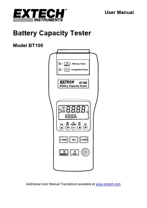
User ManualBattery Capacity TesterModel BT100Additional User Manual Translations available at IntroductionThank you for selecting the Extech Model BT100. The Battery Tester is designed for measuring the internal resistance and output voltage of batteries including lead storage cells, nickel-cadmium batteries, lithium-ion batteries, and nickel-metal hydride batteries.This device is shipped fully tested and calibrated and, with proper use, will provide years of reliable service. Please visit the Extech Instruments website () to check for the latest version of this User Guide.Features∙Accurate results are achieved using a four-terminal measurement method that eliminates lead and contact resistance.∙1kHz test current with up to 10µΩ resistance resolution.∙Dual display simultaneously indicates the internal resistance and the battery voltage.∙Comparator function with storage of up to 99 sets of resistance and voltage data for battery deterioration characterization.∙Pin type and alligator type 4-terminal Kelvin leads for quick and accurate resistance measurements.∙Memory capacity to store up to 999 (manual datalogging) or 9600 (automatic datalogging) data points.∙Supplied RS232 PC port and Windows compatible software.SafetyInternational Safety SymbolsThis symbol, adjacent to another symbol or terminal, indicates the user must refer to themanual for further information.This symbol, adjacent to a terminal, indicates that, under normal use, hazardous voltagesmay be presentDouble insulationMeter Description1. Power button: Power ON/OFF2. R READ button:① Press R button to start manually loggingreadings.② Press R READ button again to stop logging.3. M MEMORY button:① Under the manual logging mode, the testerstores a single set of logged readings to thememory by pressingM MEMORY button.② Press and hold M MEMORY button for 2seconds to enter continuous (automatic) loggingmode. Press again to stop logging.4. V-RANGE button: Select the voltage range. (4V,40V)5. HOLD button:① Press HOLD to freeze or unfreeze the displayedreading.② Press and hold the HOLD button for 2 secondsthen release, to enter the interval time (samplerate) setting for continuous data logging. Set from1 to 255 seconds. Press Set button to save andexit.6. Ω- RANGE button: Select the resistance range. (40mΩ, 400mΩ, 4Ω, 40Ω)REL button:7.① Press to move the cursor to the right.② Press REL (Relative) to zero the reading.button: Press to increase the displayed value.8.SET button:9.①Press SET to switch the comparator mode on or off.② Press and hold the SET button for 2 seconds to enter the comparator-setting mode. Pressagain to store the setting in memory.10. button: Press to decrease the displayed value.11.① Press to move the cursor to the left.②12. RS-232 connector: PC interface connector.13. – Input jack: Black test lead plug connection.14. + Input jack: Red test lead plug connection.15. LCD display (LED test status indicators are located below the LCD display)16. AC adaptor inputDisplay Description1. Measured resistance reading (or High/Low resistance limit when setting up the comparator)2. Measured voltage reading (or High/Low voltage limit when setting up the comparator)3. The comparator set number (there are 99 sets total)4. The memory location for manually logged data.Symbols:mΩ: Milliohm (resistance)V: VoltageHOLD : Hold function (display freeze)Comparator function enabledLow-BatteryBeeper enabledDATA R : Manual datalogging enabledM : Continuous datalogging enabled (flashes each time data is stored)INTV: Interval time setting for the continuous datalogging function. (1 to 255 seconds) COMP.SET : Comparator settings modeHIGH: High limit setting (threshold) for the comparatorLOW: Low limit setting (threshold) for the comparatorLED Test Status IndicatorsPASS (green LED): Battery is good (within the tolerances of the comparator’s preset limits) WARNING (yellow LED): Battery is beginning to deteriorateFAIL (red LED): Battery has failedThe LED status indications listed above are active when the High/Low comparator limits for internal resistance and the comparator threshold value for voltage are properly configured.OperationPreparation and SafetyThe following safety information must be observed to ensure maximum personal safety during the operation of this tester.∙To avoid electric shock when replacing the batteries: Disconnect the test leads from the device under test before attempting to replace the batteries.∙Check the battery polarity carefully when inserting the batteries. Refer to the battery replacement section (under Maintenance) later in this User Guide.∙Be sure to dispose of used batteries properly.∙Do not attempt to measure DC voltage exceeding 50V.∙Do not attempt to measure AC voltages; this could result in personal injury or damage to the unit.∙To avoid personal injury and/or damage to the unit, do not attempt to measure the voltage of a generator. This will result in an AC voltage being applied tothe voltage generating output terminals.∙After measuring a high voltage battery, and before continuing to measure alow voltage battery, short the measurement leads by touching the lead tipstogether. This will discharge the DC-elimination capacitor (connected acrossthe leads); otherwise a dangerous condition can exist where an excessivevoltage may be applied to the low voltage battery.Test LeadsTwo sets of test leads are supplied with the meter. Both sets provide four (4) terminal Kelvin connections which eliminate lead resistance and probe contact resistance. The application will dictate whether the alligator type or the press-probe type should be used.Testing ProcedureConnect the red test lead to the “+” jack and the black test lead to the “-” jack.1. Press the Power button to switch the tester ON.2. Use the V-RANGE or Ω-RANGE buttons to select the desired Voltage or Resistance range.3. Perform a REL Zero adjustment (see next section) each time the range is changed.4. Connect the red test probe to the positive battery terminal, and the black test probe to thenegative battery terminal.5. Read the battery’s internal resistance and the DC voltage directly on the meter’s display.Note: When the measured DC voltage or battery internal resistance value is over range, “OL” is displayed. When the AC test current faults “- - - -” will be displayed.REL Adjust (ZERO)The REL function zeros the selected range. The reading displayed when the REL button is pressed will be taken as zero and will be used to ‘offset’ subsequent measurements.1. Short the four (4) probe tips of the red and black test leads as shown in the accompanyingdiagrams.2. Press the REL button and the display will show the ‘R’ icon and the resistance and voltagevalues will zero.3. Connect the test leads to the battery to be tested.4. The REL zero adjust must be performed each time the range of the meter is changed, the testleads are swapped, or after switching between resistance and voltage tests.Comparator (99 sets)The comparator function compares the measured values with preset High and Low limit values for internal resistance and threshold voltage level, and determines the range that the measurement should fall into. Then, according to the following conditions, switches ON the corresponding LED, and sounds an audible alert as shown in the table below for the WARNING and FAIL conditions. Comparator Settings1. Press and hold the SET button for 3 seconds then release, the display will showindicating the comparator mode is enabled. 2. Use the or button to change the comparator number from 01 up to 99. 3. Use the V-RANGE or Ω-RANGE buttons to set the desired voltage and resistance measurementrange. 4. Press once, the LOW icon and the left two digits of the low limit resistance will be flashing.(Use the & buttons to select the desired value.) 5. Press once, the right two digits of the low limit resistance will be flashing. (Use theand buttons to select the desired value.) 6. Press once, the HIGH icon and the left two digits of the high limit resistance will be flashing.(Use the and buttons to select the desired value.) 7. Press once, the right two digits of the high limit resistance will be flashing. (Usethe and buttons to select the desired value.) 8. Press once, the left two digits of the threshold voltage will be flashing. (Use theand buttons to select the desired value.)9. Press once, the right two digits of the threshold voltage will be flashing. (Use theand buttons to select the desired value.)10. Repeat step 2 to step 9 to set the next comparator number. 11. Press SET again to exit the comparator setting mode.Comparator Start / Stop Controls1. Press SET to activate the comparator function, the COMP indication will appear on the display. The comparator will operate once measurements are taken.2. Use the and buttons to select the desired comparator number. The selected comparator number remains in memory even when the power is switched off. alert.4. Press SET again to switch off the comparator function.DataloggingManual Data Logging (999 sets)1. Log readings one at a time to the internal memory by pressing the MEMORY button.“DATA M NO XXX” will appear on the LCD for one second to indicate the memory location.2. Press READ button to review logged readings. The display will show “DATA R NO XXX”.3. Use the and buttons to scroll the logged readings.4. Press READ again to discontinue viewing the logged readings.Continuous Data Logging1. Press HOLD for 2 seconds, then release, and the display will show the INTV icon.2. Use the or button to select the desired interval time (datalogging sample rate) from 1second to 255 seconds.3. Press SET to save and exit the interval time setting mode.4. Press and hold MEMORY for 2 seconds to enter the continuous (automatic) logging mode, thedisplay will show the icon.5. The will flash each time a reading is stored.6. Press MEMORY again to exit the continuous datalogging mode.7. Data stored using the continuous datalogging mode cannot be read directly on the tester’sdisplay, it must be downloaded to a PC using the supplied software.Clearing the Datalogger MemoryWhen the internal memory is full, the Full icon will appear on the display and datalogging will stop.1. Press to switch OFF the tester.2. Press and hold the MEMORY button, and while continuing to hold the MEMORY button, pressthe button. The display will show the CLr icon and all datalogged readings will be cleared from memory.SpecificationsResistance measurement method Four (4) terminal Kelvin connectionsA/D conversion Dual slopeDisplays Dual LCD for measurements and programming iconsThree (3) test status LEDsDatalogger Sampling rate 1 to 255 seconds (interval time between logged readings) Open-circuit terminal voltage 3.5Vpp maxMeasurement frequency 1KHz ± 10%Input over range “OL” displayLow battery indication displayTest current fault detect “- - - -” displayAuto power off After approximately 30 minutesZero (Relative) function Circuit offset voltage is displayed as 0VHold function Display freezesAudible Alarm function Audible alert for Warning and Failure conditions (can be setON or OFF)Comparator settings Resistance High/Low limits and Voltage threshold point Number of comparator configurations 99 setsComparator output Test status LEDs for Pass (green), Warning (yellow), and Fail(red) results (audible tone for Warning and Fail conditions)Manual Datalogging memory 999 sets can be stored in meter’s internal memory Continuous (automatic) Datalogging 9600 sets can be stored in meter’s internal memory Operating conditions 0° to 40°C (32 to 104°F)80%RH (non-condensing)Storage conditions -10° to 50°C (14 to 122°F)80%RH (non-condensing)Power source Six (6) ‘AA’ 1.5V batteries; Optional 9V AC adaptor Maximum power consumption 1.0VAMaximum continuous operation 7 hours approx.Altitude 2000m max.Dimensions 250 x 100 x 45mm (9.8 x 3.9 x 1.7”)Weight 500g (1.1 lbs.) approx. (including batteries)Accessories Test Leads and batteriesOptional equipment AC adaptor (9V output)Electrical SpecificationsTo ensure accuracy the ambient temperature should be 23°C ± 5° with a humidity of 80% RH (maximum) non-condensing. In addition, perform a Zero adjustment after each range change.Resistance measurements Temperature coefficient: (±0.1% rdg ± 0.5digits)/°C Measurement frequency: 1KHz ± 10% Measurement burden voltage: 1.5mVACRange Resolution Measurement current Accuracy40m Ω 10µΩ 37.5mA approx.±(1% reading ± 10digits)400m Ω 100µΩ 3.75mA approx.4Ω 1m Ω 375µA approx. 40Ω 10m Ω 37.5µA approx.Voltage MeasurementsTemperature coefficient: (±0.1%rdg ±0.5digits)/ °CRange Resolution Accuracy4V 1mV±(0.1% reading ± 6digits)40V 10mVMaximum Input Voltage: 50VDC maximum No AC voltage input permittedMaximum voltage allowed between input terminals and ground: 60VDC/ACMaintenanceCleaning1. Repair or service not covered in this User Guide should be performed by qualified personnel only.2. Periodically wipe the case with a dry cloth; do not use abrasives or solvents.Battery Check & ReplacementThe symbol will be displayed when the batteries need replacement.1. Disconnect the test leads from the meter and from devices under test2. Switch OFF the power to the tester3. Open the battery compartment cover with a screw driver4. Replace the batteries observing polarity5. Replace and secure the battery coverBattery Safety Reminders∙Please dispose of batteries responsibly; observe local, state, and federal regulations with regard to battery disposal at all times.∙Never dispose of batteries in a fire. Batteries may explode or leak.∙Never mix battery types. Always install new batteries of the same type.As consumers, users are legally required to take used batteries to appropriate collectionsites, the retail store where the batteries were purchased, or wherever batteries are sold.not dispose of this instrument in household waste. The user is obligated to take end‐of‐lifedevices to a designated collection point for the disposal of electrical and electronic equipmentPC SoftwareOverviewThe supplied software combines data acquisition and datalogger functionality.Refer to the Software Help document that comes with the software on how to operate the software.Copyright © 2013‐2016 FLIR Systems, Inc.All rights reserved including the right of reproduction in whole or in part in any formBT100-en-GB_V4.0 11/1611。
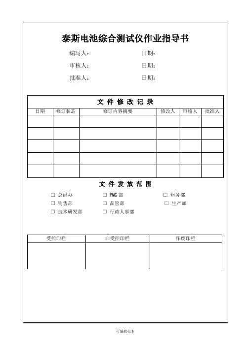

编写人: 宋金波审核人:日期:2016-8-6日期:电池综合测试仪作业指导书批准人:文件发放范围□总经办 □ PMC口财务部 □业务部□品管部 □生产部 □工程部□行政部□采购部1.0目的规定操作行为,指导正确的操作方法,保证设备的正常运转,保证产品的质量。
2.0适用范围本公司泰斯和爱维特生产的电池综合测试仪的操作。
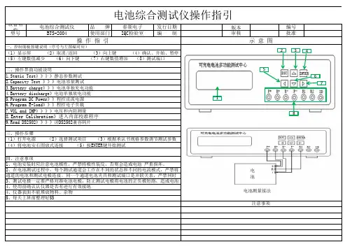
3.0定义无->1 .Static Test2. C apacity Test3. Battery Charge Battery Discharge ->1 ,静态参数测试 2 ,电池容量测试 3,电池单独充电功能 4 当所选择功能选项超过第4项之后,自动翻页到第5项,如下图显示:-> 5.Program DC Power 6. Program E-load 7. V OLandlMPEnter Calibration->5,程控直流电源 6 .程控电子负载 7 .电压和内阻测量.进入内部校准程序当所选择功能超过第8项之后,动翻页到最后一,项,如下图显示:->9.ReadDS2502 ->9 .读DS2502兼容返回 ESC向上键左键数值减少▽向下键4.0职责4.1品管人员负责对电池综合测试仪的保养与正确调式操作。
4.2品管人员对其进行参数的确认,操作的实施。
5.0程序5.1对电池综合测试仪的外部检查5.1.1测试表笔连接线完好,电源线连接完好。
5. 2综合测试操作5. 2.1打开测试仪背后电源开关;5.2.2在开机画面显示之后,进入功能菜单显示界面,如下图显示:在此功能选项中,我们只需选择第1项,静态参数测试,按确认键进入下一项选择,如下图显示:确认项始[ENTER ]5.2.3在按下确认键之后,进入参数设置界面,如下图显示:->1 .Pack type:Lion 2.Pack Vol: 3.6V3.Pack Cap:500mAh4.Lion OC/OD: YES此参数设置后面介绍,5.2.4参数设置好之后,在按下确认键之后,进入参数设置界面,如下图显示:>右键 数值增加开路电压 电池内阻 过电流保护值 当前测试状态VOL=O.OOOV TS= 0.00m < IMP= O.OmQOVC=O.OOA R1= O.OK v Test Fail: 0000000短路保护时间R1识别电阻a- TEST Fail : VOL LOW b- TEST Fail : VOL HIGHc- TEST Fail : IMPLOWd- TEST Fail : IMPHIGH表示电压偏低 表示电压偏高 表示内阻偏低 表示内阻偏高e- TEST Fail : CHARGE ERR 表示充电功能故障 f- TEST Fail : g- TEST Fail : h- TEST Fail : i- TEST Fail : j- TEST DISCHR ERR OVC LOW OVC HIGH Rl LOW R2 HIGH SHORT ERR 表示放电功能故障 表示过流保护电流偏低 表示过流保护电流偏高 表示识别电阻值偏低 表示识别电阻值偏高 表示短路保护功能不正常VOL 和V-L 交替显示,VOL 为电池开路电压,V-L 为电池负载电压TS 为电池短路保护时间,IMP 为电池内阻,OVC 为电池过电流保护电流数值 Rl 为识别电阻值(即为我司电池保护板NTC 端)5.2.5开始测试5.2.5.1测试合格,测试仪上面显示绿灯,显示器上面显示各项实测数值,测试状态显示:TESTComplete : OK525.2测试不良,测试仪上面显示红灯,并且蜂鸣器响起,显示器上面显示己检测项目数值, 测试状态显示不合格项目,不合格项目信息说明:5.2.6静态参数设置->1.Pack type:2. Pack Vol:3. Pack Cap: 54. C harge:Lion3.6V OOmAh YES->5.Discharge:YES6.Over Current:YES7.R1:YES8.R2:NO£->9.VOL-Min: 3.8V10.VOL-Max: 4.1V11.IMP-Min:50mQ12.IMP・Max:150mQ- >13.VOC・ 2.00A14.VOC-Max:7.00A15.R1・Min:7.0KQ16.R1-Max:I2.0KQ-->17.R2-Min:0.0KQ18.R2-Max:0.0KQ19.CHECK ID:No20.ID Type:Read->21.Short YES22.Short TIME:30mS23.Short Re:OPEN24.OPEN Time: 300mS->25.Detv-Max:0.2V 26.Exit Mode:Save 设置电池内阻上限Lion 锂电池(Li-ion)NiMH镣氢电池NiCd棵镉电池SLA小型铅楸电池此选项中,我司只可选Lion选择电池电出(3. 6V, 7. 2V等)此选项中・我司只可选3.6V选择电池标称容节此选项中,根据我司B0M或规格书中的标称容宰设置讫彳"1迎彳.允电汇渎此选项中-我司必洌项目,只可选YES选择是否进行放电测试此选项中,我司改剥项目,只可选YES选择是否进行过电流测试此选项中,我司必测项目,只可选YES 选择是否测试识别也阻R1此选项中,我司必测项目,只可选YES A tz H l|i| ;T ;n Mil山min此选项中,我司目前只有一个识别电阻端•逸掉是a测试识别电阻R2 R1测试之后.R2可以选择NO设轮电池电压卜'限此设置中・我司设置3^8V里客巳笠遂要不除夕卜?设置电池电压上限此设置中,我司设*. IV《客户特殊要求除外)V电池内阻下限此设■中,我司设(客户特殊要求除外)此设置中.我司设置150mD (客户特殊要求除外),仕心& 此设着中,根据〈规格书〉或<BOM>中要求设置.一设户L过电流保护卜限般单MOS设置2. 00A.双而S设置5. 00A■I由此设置中,根据〈规格书〉或<B0i>*要求设置,一设fl.廷电流侏炉上限般单M0S设置7. 00A.双MOS设置12. 00ACHI此设置中,根据〈规格书>§£<B0M>中要求设置.一«为I只别电HIR1 h限般设置7 0KQ,客户特殊要求除外) _ _ 4as{n H||由IJH RI k KB此设置中,根据〈规格书〉或<B0M>中要求设置.一攻直职刎吧阳KI工眼殷设置12 QKQ(客户特殊要__________设咒识别电R1R2T限此设置中二第8项选择N0.此项不用设置设置识别电阻R2下限此设置中[第8项选择N0〉此项不用设il 选择是否测试码片以及种类皆菁费4费杲箱瞥有生产带码选择码片型号此设置中,第19项选择N0,此项不用设置设徂是否允许短路测试此选顼中•.我司必倒项目•只可选您设咒短路保护最大允许时间此设置中.我司目前设置为30mS 设置短路保护后自恢复方式此设置中.我司目前设置为OPEN开路恢复模式,不选择Charge充电恢复模式设置开路恢复时间此设置中,我司目前设置时间为30也§设置负载电压卜降的最大值些送煎电,我回旦画[殳置和癸选择退出设置菜单模式,可选择模式有:Save饪次保存当前设置No Save当前设置不保存Reset恢复到出厂设置状态此设骂中.为了方便下次设置.每次保存当前设置模式选择Save。
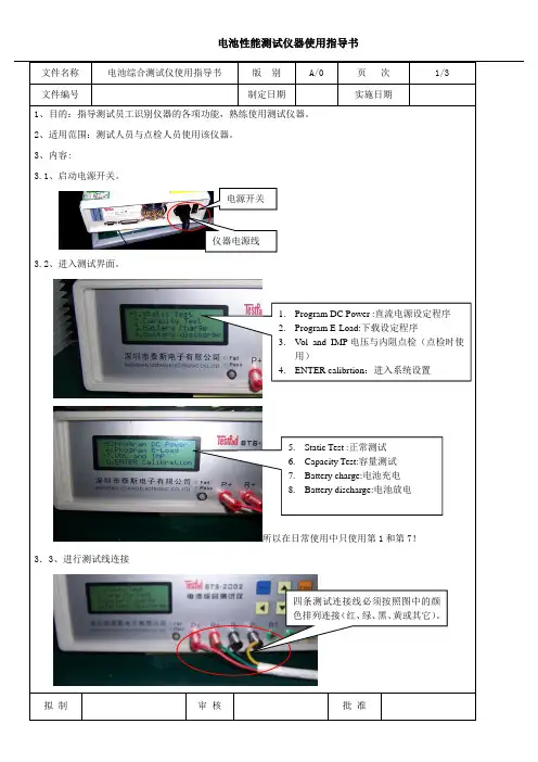
文件编号制定日期实施日期1、目的:指导测试员工识别仪器的各项功能,熟练使用测试仪器。
2、适用范围:测试人员与点检人员使用该仪器。
3、内容:3.1、启动电源开关。
电源开关仪器电源线3.2、进入测试界面。
1.Program DC Power :直流电源设定程序2.Program E-Load:下载设定程序3.V ol and IMP电压与内阻点检(点检时使用)4.ENTER calibrtion:进入系统设置5.Static Test :正常测试6.Capacity Test:容量测试7.Battery charge:电池充电8.Battery discharge:电池放电所以在日常使用中只使用第1和第7!3.3、进行测试线连接四条测试连接线必须按照图中的颜色排列连接(红、绿、黑、黄或其它)。
拟制审核批准文件编号制定日期实施日期3. 4、按上下键选择测试项目。
3.5、正常测试选择1 Static Test ,进入下一级测试设定菜单。
拟 制审 核批 准向上键 向下键选定指针选定测试项目之后按“ENTER ”键进入下一级菜单。
1.Pack type :Lion (封装种类:我们选用锂电)2.Pack V ol :电压(单节电池选择3.60v ) 3.:Pack Cap :容量(依据生产的电池来选择,点检时设定为200。
)4.Charge :充电(一般选择YES )5. Discharge :放电(选择YES )6.Over Current :过流测试(一般选择YES ,蓝牙电池选择NO )7.:R1:电阻1(没有连接线,选择NO) 8.R2:电阻2(没有连接线,选择NO)左、右用于选择项目和数字变化,左键减小,右键增大。
文件名称电池综合测试仪使用指导书版别A/0 页次3/3 文件编号制定日期实施日期9. V oL-Min:输出电压下限(根据产品工艺设定,点检时设定为3.80V)10.V ol-Max:输出电压上限(根据产品工艺设定,点检时设定为4.00V)11.:IMP-Min:内阻测试(根据产品工艺设定,一般设定为50,点检时设定为80)12. IMP-Min:内阻测试(根据产品工艺设定点检时设定为280)13. Ovc-Min:过流测试下限(一般设定为1.2,点检也一样)14. Ovc-Max:过流测试上限(一般设定为7.2,点检时设定为7.5)15.:R1-Min:不须设定16. R1-Min:不须设定17.:R2-Min:不须设定18. R2-Min:不须设定19.CHECK ID:ID 检测(设定为NO)20. LOAD: 负载电阻(设定为2或4欧姆根据工艺参数卡设定)21.:Short TEST:YES(短路测试设定为YES)22. Short TEST:(设定为30mS)23. Short Re:Charge短路恢复方式(Charge)24.OPEN TIME: 断开时间(设定为200mS)25.detV-Max:电压差(2欧姆负载设定为0.8,4欧姆负载设定为0.5)26.Exit Mode:退出模式(设定为“Save”保存设置)以上设定完成后,进入测试;多节大电流电池由技术人员调试。
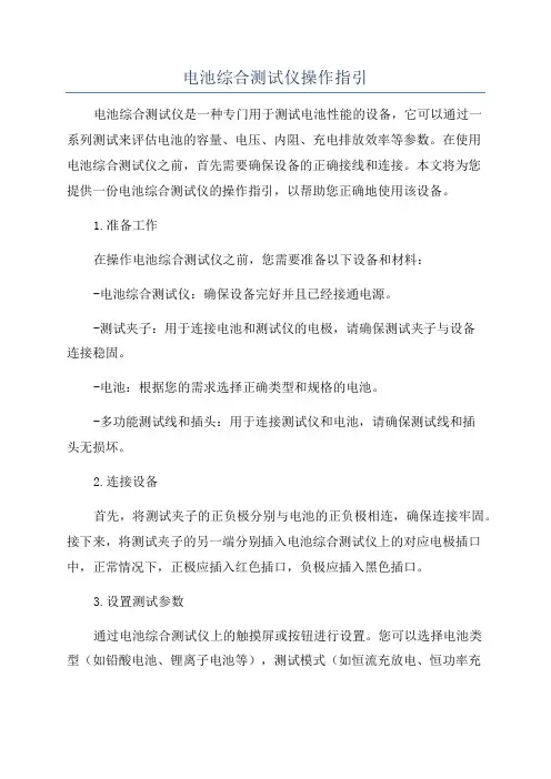
电池综合测试仪操作指引电池综合测试仪是一种专门用于测试电池性能的设备,它可以通过一系列测试来评估电池的容量、电压、内阻、充电排放效率等参数。
在使用电池综合测试仪之前,首先需要确保设备的正确接线和连接。
本文将为您提供一份电池综合测试仪的操作指引,以帮助您正确地使用该设备。
1.准备工作在操作电池综合测试仪之前,您需要准备以下设备和材料:-电池综合测试仪:确保设备完好并且已经接通电源。
-测试夹子:用于连接电池和测试仪的电极,请确保测试夹子与设备连接稳固。
-电池:根据您的需求选择正确类型和规格的电池。
-多功能测试线和插头:用于连接测试仪和电池,请确保测试线和插头无损坏。
2.连接设备首先,将测试夹子的正负极分别与电池的正负极相连,确保连接牢固。
接下来,将测试夹子的另一端分别插入电池综合测试仪上的对应电极插口中,正常情况下,正极应插入红色插口,负极应插入黑色插口。
3.设置测试参数通过电池综合测试仪上的触摸屏或按钮进行设置。
您可以选择电池类型(如铅酸电池、锂离子电池等),测试模式(如恒流充放电、恒功率充放电等)和测试参数(如充电电流、放电电流等)。
根据您的实际需求和电池规格,设置适当的测试参数。
4.进行电池测试在完成参数设置后,您可以开始进行电池测试。
电池综合测试仪会根据您的设置,进行充电、放电或循环测试等操作。
您可以监视测试仪上的显示屏,实时查看电池的电压、电流和容量等信息。
5.分析测试结果测试完成后,您可以查看电池综合测试仪上所显示的测试结果和图表。
根据这些数据,您可以分析电池的性能和健康状况,判断是否需要更换电池或进行其他维护措施。
6.安全操作在操作电池综合测试仪时-使用适当类型和规格的电池,确保测试仪的电压和电流不超过电池的额定范围。
-确保测试夹子和测试线插头的连接牢固,避免电流过大或接触不良导致的安全事故。
-在进行高电流测试时,注意防止电池过热或短路,提前做好散热和防护措施。
-使用绝缘手套、眼镜等个人防护用品,确保测试过程中的人身安全。

电池综合测试仪BTS-4002用户手册版本:1.0深圳市泰斯电子有限公司2012年3月l 在第一次使用本产品前,请详细阅读【用户手册】。
l 本机所附电源线内包含安全接地线,请确保电源插座安全接地线接地良好,在生产线场合固定使用时,请使用额外接地线连接机器后背板的安全接地螺丝孔。
l 本测试仪电路设计上不支持电池反接,在连接电池到电池测试仪前,请确认电池正负极和测试仪正负极连接线是否正确,如果反接,可能会因为电池放电电流过大导致电池或者测试仪器损坏。
l 本测试仪支持用户调整测试仪内部散热风扇运转速度,在环境温度高以及高负荷连续使用测试仪情况下,请勿将测试仪风扇速度设置为0,以免测试仪内部温度过高,影响测试精度或者导致测试仪故障。
l 本测试仪内无任何用户可以调整更换的零件或者保险丝等易损件,在未得到本公司书面许可情况下,严禁私自打开机壳,否则会影响设备保修目录1 产品概述 42 外观特性 52.1 前面板设计 52.2 键盘界面 62.3 接线端口72.4 后背板设计83 开机界面94 测试项目和参数设置104.1 参数说明104.2 测试功能描述124.3 测试步骤设置215 选项设置235.1 测试选项235.2 条码选项265.3 其他选项(信号指示)285.4 通信选项296 测试操作306.1 电池接线方式306.2 启动触发信号316.3 输出信号326.4 测试界面显示336.5 历史数据查看357 校准操作367.1 电压校准367.2 电压电流校准377.3 内阻校准387.4 其他参数校准398 特性指标401. 产品概述电池综合测试仪是一种能够快速检测电池的各项性能参数的专用测试设备,主要应用于电池生产厂家的电池生产检测,电池应用厂家电池来料检验等等用途,能够快速鉴别电池的性能指标,性能参数是否符合要求,能够根据设定参数快速判断电池是否为合格品。
深圳市泰斯电子有限公司成立多年,从最早第一代电池测试仪产品BTS-2002系列推向市场以来,得到电池生产厂家一致认同和广泛应用,在客户的大批量使用条件下,结合实际产品,不断升级;改善,从最早的1.0版本到最新的BTS-2002H的V5.9版,性能不断升级,在BTS-2002H基础上,升级到BTS-3002版本,也得到很多高端客户的认同,BTS-4002系列产品是在结合前两代的基础和优势下,新推出的最新一代电池测试仪产品,完全采用全新的设计,主控芯片采用ST公司新推出的32位ARM处理器,模拟器件采用ADI的高速16位模拟数字转换芯片,在整体精度和性能上有脱胎换骨的表现,具体表现在测试精度更高,测试速度更快,用户设置自定义更灵活,支持测试步骤自定义等等一系列的人性化改造升级。
可充电电池综合测试仪操作说明书BTS-2002深圳市泰斯电子有限公司2005/04/06目录1,前言第3页2,功能概述第5页3,仪器外观第7页4,接线方式第8页5,主功能菜单第9页6,电池静态参数测量模式第10页7,电池容量测量模式第13页8,单独充电模式第16页9,单独放电模式第16页10,程控电源模式第16页11,程控电子负载模式第17页12,电压与内阻表模式第18页13,仪器校准模式第18页14,仪器特性指标第19页15,客户反馈意见表第21页前言常见的可充电电池包含锂电池,镍镉电池,镍氢电池,以及密封铅酸蓄电池等其中,锂电池具有容量大,重量轻,循环次数高等特点,广泛应用于移动电话,PDA,数码相机,摄像机,笔记本电脑等领域,是目前最为先进的可充电电池,这里所指锂电池是成品锂电池包,由锂电芯(锂离子电芯或者里聚合物电芯)加锂电池保护板组成镍镉电池是比较早应用的可充电电池,具有成本较低,低内阻,能够大电流放电的特点,至今在一些电动工具,电动车上面有广泛应用。
镍氢电池和镍镉电池类似,但是因为不含重金属,所以对环境的污染较小,目前在一些常见的消费类电子产品中应用广泛,已基本取代以前镍镉电池的应用领域。
小型密封铅酸电池,又称免维护铅酸电池,目前工艺成熟,目前主要应用在固定式后备电源场合,如不间断电源,应急照明灯等等场合。
针对这些可充电电池的生产检测需要,特研制了专用的可充电池综合检测仪,本测试仪可以对电池的一些基本参数做一个定量的精确的测量,可以测量电池的开路电压,内阻,充电,放电性能,电池容量特别针对锂电池的功能还有过充电保护,过放电保护,过电流保护等功能,并测出过相应的数值,极大的方便了电池的生产和售前售后服务工作,采用非常简单的几个步骤就可以直观的判断电池的性能和好坏,同时也具有快速筛选的功能,可以设定测量参数的上限和下限,可以容易的从一批电池成品中快速检测出不良电池,提高的生产效率。
另外,也附加了一些特别的功能,使之具有一些通用仪器设备的特征,扩大了设备的使用灵活性,以及具有用用范围广泛的特点。
电池综合测试仪操作指引1.0目的规范电池综合功能测试仪的操作、保管与维护。
2.0范围适用公司内BTS-2004型号的电池综合功能测试仪。
3.0定义无4.0职责4.1品质部为本指导书的权责单位。
4.2各使用部门遵守本操作指引。
5.0操作内容5.1基本功能与外观1)电池静态参数快速检测; 2)电池容量检测3)可单独选择的电池充电功能;4)可单独选择的电池放电功能。
5)数控电流电压源功能; 6)数控电子负载功能。
7)电压和内阻表功能; 8)仪器校准功能9)读码,用来显示操作和测量信息的LCD 显示器,操作键盘,以及接线孔,如图所示:个轻触按键,分别是向上键,向下键,左键(减少),右键(增加),取消键(返回),确认键(开始/暂停)键。
在任何一个操作界面中,按取消键都可以退出当前操作,并返回上一级菜单,如当前在设置状态,按确认键则启动运行,如在运行状态,按确认键可以暂停当前操作,再次按下确认键,可以再次启动当前运行。
个接线端子,其中P+,P-分别连接到电池的正极和负极,作为充电电流和放电电流的连接通道,另外,R+,R-也分别用独立的两根导线连接到电池的正极和负极。
并在电池极片上汇合,作为测量信号的连接通道,这样测量的时候,通过4线制测量,可以消除导线带来的测量误差,提高测试精度。
另外R1,和R2 分别作为电池内部识别ID 电阻或者热敏电阻的连接端子,如需要的话,可以用导线连接到相应端子,ID 线用于测量一些带码片的电池,目前此项功能可选。
,测量该电池共需要5根连接线,其中P+,R+分别用两根导线连接到电池的正极,P-,R-分别用两根导线连接到电池的负极,这样可以获得精确的内阻测量结果,如不需要精确的内阻测量结果,也可以把P+,R+直接并联,P-和R-直接并联,然后再分别连接到电池的正极和负极,这样除内阻测试的电阻值可能偏大外,无其他不良影响。
如需要测试识别电阻或者热敏电阻,可将单独的导线连接到测试仪R1/R2 端到电池的对应端子。