牛顿环实验指导书范文
- 格式:doc
- 大小:63.50 KB
- 文档页数:7

牛顿环物理实验报告【篇一:用牛顿环测量透镜的曲率半径实验报告】一、实验名称:用牛顿环测量透镜的曲率半径二、实验目的:1、观察光的等厚干涉现象,了解干涉条纹特点。
2、利用干涉原理测透镜曲率半径。
3、学习用逐差法处理实验数据的方法。
三、实验仪器:牛顿环装置(其中透镜的曲率未知)、钠光灯(波长为589.3nm)、读数显微镜(附有反射镜)。
四、实验原理:将一块曲率半径r较大的平凸透镜的凸面放在一个光学平板玻璃上,使平凸透镜的球面aob和平面玻璃cd面相切于o点,组成牛顿环装置,如图所示,则在平凸透镜球面和平板玻璃之间形成一个以接触点o为中心向四周逐渐增厚的空气劈尖。
当单色平行光束近乎垂直地向ab面入射时,一部分光束在aob面上反射,一部分继续前进,到cod面上反射。
这两束反射光在aob面相遇,互相干涉,形成明暗条纹。
由于aob面是球面,和o点等距的各点对o点是对称的,因而上述明暗条纹排成如图所示的明暗相间的圆环图样,在中心有一暗点(实际观察是一个圆斑),这些环纹称为牛顿环。
图(4)牛顿环装置图(5)牛顿环根据理论计算可知,和k级条纹对应的两束相干光的光程差为? 2?式中e为第k级条纹对应的空气膜的厚度,为半波损失。
2?由干涉条件可知,当??(2k?1)(k?0,1,2,3,?)时,干涉条纹为暗条纹。
即2解得??2e?e?k(2) 2设透镜的曲率半径为r,和接触点o相距为r处空气层的厚度为e,由图4所示几何关系可得r2??r?e??r2?r2?2re?e2?r2 由于r??e,则e2可以略去。
则r2e?(3)2r2?由式(2)和式(3)可得第k级暗环的半径为rk2?2re?kr? (4)由式(4)可知,如果单色光源的波长?已知,只需测出第k级暗环的半径rk,即可算出平凸透镜的曲率半径r;反之,如果r已知,测出rk后,就可计算出入射单色光波的波长?。
但是由于平凸透镜的凸面和光学平玻璃平面不可能是理想的点接触;接触压力会引起局部弹性形变,使接触处成为一个圆形平面,干涉环中心为一暗斑;或者空气间隙层中有了尘埃等因素的存在使得在光程差公式中附加了一项。

LABORATORY MANUAL FORNEWTON’S RING METHODBackground Coherent sources of light,Concept of Interference,Interference by division of wave front and amplitude,Interference in thinfilms,Newton’s ring apparatus.Aim:To determine the wavelength of sodium light by Newton’s Ring method.Apparatus:A nearly monochromatic source of light(source of sodium light),a plano-convex lens C,an optically plane glass plate P,an opticallyflat glass plate G in-clined at an angle of45◦,a travelling microscope with measuring scale and a spherometer.Theory:•Condition for formation of bright and dark fringes:When a parallel beam of monochromatic light is incident normally on a combination of a plano-convex lens C and a glass plate P,as shown infig.1(a),a part of each incident ray is reflected from the lower surface of the lens,and a part,after refraction through thefilm between the lens and the plate,is reflected back from the surface of glass plate. These two reflected rays are coherent,hence they will interfere and produce a system of alternate dark and bright rings(seefig.1(b))with the point of contact between the lens and the plate at the center.These rings are known as Newton’s rings.(a)Experimental set-up(b)Newton’s ringsFigure1In general,the path difference between the reflected light beams which are undergoing interference(for oblique incidence)is given by∆=2µtcosθ−λ2,(1)where additional path difference ofλ2is because one of the interfering beam is reflected fromfilm to glass surface.Also,θis the angle of incidence.For normal incidenceθ=0◦and hence,the path difference will be∆=2µt−λ2.(2)In the interference pattern bright fringe will be formed if the path difference is equal to integral multiple of wavelength of light,i.e.,∆=2µt−λ2=nλ;n=0,1,2,3...⇒2µt=(n+12)λ;n=0,1,2,3 (3)For intensity minima(dark fringe),∆=(n+12)λ,and thus,2µt=nλ.n=0,1,2,3 (4)•Relationship between ring diameter and wavelength:Figure2Infig.2,let LOL is the plano-convex lens placed on glass plate.Plano-convex lens appears as part of circle of radius R.Here,radius R is known as radius of curvature of plano-convex lens.Suppose r is the radius of some n th bright ring having thickness ing the property of circle,fromfig.(2),we can writeEP×P F=P O×P Q,⇒r2n=t×(2R−t),⇒r2n=(2Rt−t2).Since R>>t,t2can be neglected thereforer2n2Rt,(5)by using Eq.(4)and Eq.(5),we haver2 n =nλRµ.(6)Using r n=D n2,we can write following relation for diameter of n th,ringD2n =2r2n=nλRµ.(7)The diameter of some m t h dark fringe will beD2m =mλRµ.(8)Subtracting Eq.(7)and Eq.(8),we can write following relationλ=D2n−D2m4R(n−m)µ.(9)Above equation is used tofind the wavelength of monochromatic light using Newton ring’s method,in which material of refractive indexµis immersed between plano-convex lens and glass plate.If air is enclosed as thinfilm havingµ=1,then Eq.(9)becomesλ=D2n−D2m4R(n−m).(10)The radius of curvature,R is calculated by spherometer(seefig.3)using followingrelationR=l26h+h2.In above,l is the mean length of the three sides of equilateral triangle formed by joining the tips of three outer legs and h represents the height of the central screw above or below the plane of the outer legs.Procedure:The experimental set-up used for the experiment is shown infig.1(a).1.Level the travelling microscope table and set the microscope tube in a verticalposition.Find the vernier constant(least count)of the horizontal scale of the travelling microscope.2.Clean the surface of the inclined glass plate G,the lens C and the glass plate P.Place them in position as shown infig.1(a)and as discussed in the description of apparatus.Place the arrangement in front of a sodium lamp so that the height of the center of the glass plate G is the same as that of the center of the sodium lamp.Figure3:Spherometer.3.Adjust the position of the travelling microscope so that it lies vertically above thecenter of lens C.Focus the microscope,so that alternate dark and bright rings are clearly visible.4.Adjust the position of the travelling microscope till the point of inter-section of thecross wires(attached in the microscope eyepiece)coincides with the center of the ring system.5.Slide the microscope to the left till the cross wire lies tangentially at the centerof the20th dark ring.Note the reading on the vernier scale of the microscope.Slide the microscope backward with the help of the slow motion screw and note the readings when the cross-wire lies tangentially at the center(seefig.1(b))of the 18th,16th,14th,12th,10th,8th,6th,and4th dark rings,respectively.[Observations offirst few rings from the center are generally not taken because it is difficult to adjust the cross-wire in the middle of these rings owing to their large width.]6.Keep on sliding the microscope to the right and note the reading when the cross-wire again lies tangentially at the center of the4th,6th,8th,10th,12th,14th,16th, 18th,and20th dark rings,respectively.7.Remove the plano-convex lens C andfind the radius of curvature of the surface ofthe lens in contact with the glass plate P accurately using a spherometer.8.Find the diameter of the each ring from the difference of the observations taken onthe left and right side of its center.9.Take any two diameter and perform the calculations for D2n −D2m(m<n)as directedin Table.1.10.Finally calculate the value of wavelength of the sodium light source using Eq.(9).Observations:DiameterFigure 4:Vernier Scale of the Microscope.1.M.S.D =....2.V.S.D =....3.Vernier constant =...cm.4.µ(air)=....Sr.no.Ring no.(n )Microscope reading (cm)D n =L-R (cm)D 2n (cm 2)D 2n −D 2m (cm 2)Left(L)Right(R)Main Vernier Total Main Vernier Total12345678910Table 1:Measurements of the diameter of the ring.Spherometer1.Pitch of the screw=.........cm.2.Number of divisions on circular head=..........3.Least count of the spherometer=..........cm.Sr.no.Spherometer readings onh(cm)l(cm) convex surface plane surface1.2.3.Table2:Calculations of h and l.4.The mean height h of the central screw=.......cm and the mean distancebetween the two legs of the spherometer,l=.........cm.5.The radius of curvature R=.........cm.WavelengthSr.no.λ=D2n−D2m4R(n−m)µ(nm)1.2.3.4.5.6.7.8.9.Table3:Calculations for wavelengthλ.•The mean wavelength(λ)of Sodium light is=.........nm. Results:•Observed wavelength of the Sodium light is(λO):.......nm.•Actual wavelength(λA):589.3nm.•%error:|λO−λA|×100=.....%.λAPrecautions:Notice that as you go away from the central dark spot the fringe width decreases.In order to minimize the errors in measurement of the diameter of the rings the following precautions should be taken:1.The microscope should be parallel to the edge of the glass plate.2.The mirrors should be in perfectly stable positions when reading are being taken.3.There should be no play between the screw and the nut in which it rotates.4.To avoid any backlash error,the micrometer screw of the travelling microscopeshould be moved very slowly and be moved in one direction while taking observa-tions.5.While measuring diameters,the microscope cross-wire should be adjusted in themiddle of the ring(seefig.1(b)).Sample viva voce questions:1.What do you understand by the interference of light?2.What are essential conditions for obtaining interference of light?3.What do you understand by coherent sources?4.Is it possible to observe interference pattern by having two independent sourcessuch as two sodium lamp?5.Fro the interference to happen,why two sources should be monochromatic?6.Why are the Newton’s rings circular?7.Why is central ring dark?8.Where are these rings formed?9.Sometimes these rings are elliptical or distorted,why?10.What is the difference between the rings observed by reflected light and thoseobserved by transmitted light?11.What will happen if the glass plate is silvered on the front surface?12.Why do the rings gets closer andfiner as we move away from the center?13.What will happen when a little water is introduced in between the plano-convexlens and the plate?14.How does the diameter of rings change on the introduction of liquid?15.Can youfind out the refractive index of a liquid by this experiment? References•F.Jenkins and H.White,Fundamental of Optics,TATA-McGRAW HILL.•A.Ghatak,Optics,TATA-McGRAW HILL.Note:Soft copy of this manual is available on http://www.nitj.ac.in/physics/。

大学物理牛顿环实验一、实验目的1、观察牛顿环的干涉现象2、研究干涉现象与光波的波动性质3、学习使用分光仪、读数显微镜的方法二、实验原理牛顿环是一种典型的干涉现象,它是由一束光分成两束相干光,在空间叠加而成。
当一束光照射在玻璃表面时,会产生反射和透射两种现象。
反射光会在玻璃表面形成亮斑,而透射光则会继续传播。
当透射光再次照射到玻璃表面时,会再次产生反射和透射,形成一系列的反射和透射光。
这些反射和透射光会相互干涉,形成明暗相间的条纹,这就是牛顿环。
三、实验步骤1、调整分光仪,使一束光通过玻璃棱镜,分成两束相干光,并在空间叠加。
2、调整分光仪的望远镜,观察到清晰的牛顿环。
3、使用读数显微镜测量牛顿环的直径,并记录下来。
4、改变分光仪的棱镜角度,观察干涉条纹的变化,并记录下来。
5、分析实验数据,得出结论。
四、实验结果与分析1、实验结果在实验中,我们观察到了清晰的牛顿环干涉现象,并且使用读数显微镜测量了牛顿环的直径。
随着分光仪棱镜角度的变化,干涉条纹也会发生变化。
2、结果分析通过实验数据,我们可以得出以下(1)牛顿环是由两束相干光在空间叠加而形成的干涉现象。
(2)干涉条纹的明暗交替是由于两束光的相位差引起的。
(3)通过测量牛顿环的直径,我们可以计算出光波的波长。
(4)随着分光仪棱镜角度的变化,干涉条纹会发生变化,这是因为光的波长和入射角发生了变化。
五、结论通过本次实验,我们深入了解了干涉现象与光波的波动性质,学习了使用分光仪、读数显微镜的方法。
这对于我们今后在光学领域的研究具有重要意义。
大学物理牛顿环实验一、实验目的1、观察牛顿环的干涉现象2、研究干涉现象与光波的波动性质3、学习使用分光仪、读数显微镜的方法二、实验原理牛顿环是一种典型的干涉现象,它是由一束光分成两束相干光,在空间叠加而成。
当一束光照射在玻璃表面时,会产生反射和透射两种现象。
反射光会在玻璃表面形成亮斑,而透射光则会继续传播。
当透射光再次照射到玻璃表面时,会再次产生反射和透射,形成一系列的反射和透射光。
第1篇一、实验背景牛顿环实验是光学中的一个经典实验,通过观察和分析牛顿环现象,可以深入了解光的干涉原理,并应用于测量透镜的曲率半径等实际应用中。
牛顿环实验的核心原理是等厚干涉现象,即在薄膜层厚度相同的位置,光波发生干涉,形成明暗相间的条纹。
二、实验原理1. 牛顿环的形成牛顿环实验装置主要由一块曲率半径较大的平凸透镜和一块光学玻璃平板组成。
当平凸透镜的凸面与平板接触时,在接触点附近形成一层空气膜。
当平行单色光垂直照射到牛顿环装置上时,光在空气膜的上、下表面反射,形成两束光波。
这两束光波在空气膜上表面相遇,产生干涉现象。
2. 等厚干涉现象在牛顿环装置中,空气膜的厚度从中心到边缘逐渐增加。
由于空气膜厚度相同的位置对应于同一干涉条纹,因此这种现象称为等厚干涉。
根据等厚干涉原理,厚度相同的位置,光程差也相同,从而形成明暗相间的干涉条纹。
3. 牛顿环的干涉条件在牛顿环装置中,光在空气膜上、下表面反射的两束光波发生干涉,干涉条件为:Δ = mλ其中,Δ为光程差,m为干涉级次,λ为光波长。
4. 牛顿环的半径与透镜曲率半径的关系设牛顿环装置中第m级暗环的半径为rk,透镜的曲率半径为R,空气膜厚度为e,则有:rk^2 = R^2 - e^2由上式可知,通过测量牛顿环的半径rk,可以计算出透镜的曲率半径R。
三、实验步骤1. 准备实验装置,包括牛顿环仪、钠光灯、凸透镜、平板玻璃等。
2. 将牛顿环仪放置在实验台上,调整透镜与平板玻璃之间的距离,使牛顿环清晰可见。
3. 打开钠光灯,调整显微镜的焦距,使牛顿环图像清晰。
4. 测量第m级暗环的半径rk,重复多次测量,求平均值。
5. 根据测量结果,利用上述公式计算透镜的曲率半径R。
四、实验结果与分析通过实验测量,可以得到一系列牛顿环的半径rk。
根据实验原理,可以计算出透镜的曲率半径R。
通过对比实际值与测量值,可以分析实验误差,并探讨提高实验精度的方法。
五、实验结论牛顿环实验是一种经典的干涉实验,通过观察和分析牛顿环现象,可以深入了解光的干涉原理,并应用于测量透镜的曲率半径等实际应用中。

牛顿环详案或者教案-湖南高校通用第一篇:牛顿环详案或者教案-湖南高校通用实验8.牛顿环测透镜的曲率半径教学目的1、理解等厚干涉形成牛顿环的机理;2、掌握用牛顿环测量平凸透镜曲率半径的方法;3、掌握读数显微镜的调节及使用方法。
教学重点1、清晰牛顿环图案的调整;2、利用牛顿环测量平凸透镜曲率半径的方法;3、除读数显微镜的空回误差。
教学难点1、清晰牛顿环图案的调整;2、消除读数显微镜的空回误差。
课型:提高性实验(2学时)教学内容:1、牛顿环的产生原因;2、消除系统误差的方法介绍;3、读数显微镜的使用及注意事项4、用牛顿环测量平凸透镜曲率半径的方法教学方法:讲解教学内容,明确其重点和难点,然后实际演示操作要点课件:PPT 教学手段学生操作,随堂检查操作情况。
根据学生的操作情况将容易犯错的问题做重点提示,学生可以根据操作中遇到的具体问题个别提问。
教学过程【课前的准备】:1.仪器设备的检查,注意要校零。
2.实验的预做(采集三组以上数据进行处理)。
3.作出数据表格设计的参考。
【课上的常规检查】预习报告、数据表格的设计等 1 引言“牛顿环”是牛顿在1675年制作天文望远镜时,偶然把一个望远镜的物镜放在平板玻璃上发现的。
因为是牛顿发现的,所以称为牛顿环。
牛顿环实际上是一种利用分振方法实现等厚干涉现象,实验原理并不复杂,但却有其研究价值和实用意义。
牛顿实验原理——光的干涉广泛应用于科学研究,工业生产和检验技术中。
如:利用光的干涉法进行薄膜等厚、微小角度、曲面的曲率半径等几何量的精密测量,也普遍应用于检测加工工件表面的光洁度和平整度及机械零件的内力分布等。
因此不管对于科学研究还是实验教学,研究牛顿环是很有意义的。
牛顿环干涉实验是大学物理实验中的一个经典实验项目,几乎所有的理科大学都开设有这样一个实验。
牛顿环实验既能够培养学生的基本实验技能,又能提高学生解决问题的能力。
学生们在做此实验的过程中往往都需要眼睛紧紧地盯着显微镜目镜仔细观察,同时还需要移动牛顿环装置和调焦手轮,寻找最清晰的干涉条纹并要移动到最佳观察位置。
实验六 牛顿环光的干涉现象在科学研究和工业生产上有着广泛的应用,如测量光波波长、精确地测量微小物的长度、厚度和角度,检验物体表面光洁度等。
本实验将利用光的等厚干涉现象之一的牛顿环来测量平凸透镜的曲率半径及光波波长,同时也可选做利用劈尖干涉测量细丝的直径。
【实验目的】1.熟悉读数显微镜的调整和使用,掌握消除螺距误差的方法。
2.观察等厚干涉现象—牛顿环,加强对干涉现象的认识。
并学习利用干涉现象测量平凸透镜的曲率半径或微小厚度的方法,以及光波波长相对测定的方法。
3.学习用逐差法或外推法处理实验数据。
【实验原理】1.利用牛顿环测透镜曲率半径。
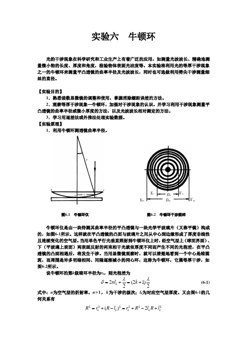
图6-1 牛顿环仪 图6-2 牛顿环干涉图样牛顿环仪是由一块待测其曲率半径的平凸透镜与一块光学平玻璃片(又称平镜)构成的,如图6-1所示。
这样就在平凸透镜的凸面与玻璃片之间从中心到边缘形成了厚度非线性且连续变化的空气层。
当用单色平行光垂直照射到牛顿环仪上时,经空气层上(球面界面)、下(平玻璃上表面)两表面反射的两束相干光就依厚度不同而产生不同的光程差,在平凸透镜的凸面相遇后,将发生干涉。
当用显微镜观察时,就可以清楚地看到一个中心是暗圆斑,而周围是许多明暗相间、间隔逐渐减小的同心环,这称为牛顿环,它属等厚干涉,如图6-2所示。
设牛顿环的第k 级暗环半径为r k ,则光程差为2(21)22k nl k λλδ=+=+ (6-1)式中:n 为空气层的折射率,n=1,k 为干涉的级次;l k 为对应空气层厚度。
又由图6-1的几何关系有222222()2k k k k k R r R l r R l R l =+-=+-+D n D mX nX ´n由于R >>l k ,故略去2k l 项,解得22k k r l R=整理后得牛顿环暗纹半径公式为2(0,1,2,3,)k r kR k λ== (6-2)则干涉环直径公式为24(0,1,2,3,)k D kR k λ== (6-3)原则上可以通过上式经测得第k 级暗环的直径或半径,在已知单色光波λ的情况下,即可计算出透镜的曲率半径R (或已知R 求λ)。
一、实验目的1. 观察光的等厚干涉现象,了解干涉条纹的特点。
2. 学习利用干涉现象测量透镜的曲率半径。
3. 理解牛顿环的成因及其在光学测量中的应用。
二、实验原理牛顿环是一种典型的等厚干涉现象。
当一束单色光垂直照射到平凸透镜与平板之间形成的空气薄层时,光在空气薄层上下表面反射后发生干涉,形成一系列明暗相间的同心圆环,称为牛顿环。
根据干涉原理,当两束光的光程差为波长的整数倍时,发生相长干涉,形成明环;当光程差为半波长的奇数倍时,发生相消干涉,形成暗环。
设空气薄层厚度为d,入射光的波长为λ,则对于第k级明环和暗环,有:- 明环:2d = kλ- 暗环:2d = (k + 1/2)λ通过测量牛顿环的直径,可以计算出透镜的曲率半径。
设第k级明环的直径为D,则曲率半径R与D的关系为:R = (kλ)² / D三、实验仪器1. 牛顿环仪2. 平面玻璃板3. 凸透镜4. 钠光灯5. 读数显微镜6. 秒表四、实验步骤1. 将牛顿环仪调整至水平状态,并将平面玻璃板放置在仪器的支架上。
2. 将凸透镜放置在玻璃板上,使其凸面与玻璃板接触。
3. 打开钠光灯,调整其高度,使光线垂直照射到牛顿环仪上。
4. 使用读数显微镜观察牛顿环,记录下第k级明环和暗环的直径D。
5. 重复步骤4,记录多组数据。
五、数据处理1. 根据实验数据,计算第k级明环和暗环的厚度d。
2. 利用公式R = (kλ)² / D,计算透镜的曲率半径R。
3. 求出所有数据的平均值,作为最终结果。
六、实验结果与分析通过实验,我们观察到了牛顿环的等厚干涉现象,并成功测量了透镜的曲率半径。
实验结果表明,牛顿环的直径与透镜的曲率半径之间存在一定的关系,验证了实验原理的正确性。
七、实验结论1. 牛顿环实验是一种简单易行的光学干涉实验,可以用于观察光的等厚干涉现象。
2. 利用牛顿环可以测量透镜的曲率半径,具有很高的精度。
3. 牛顿环实验在光学测量和光学仪器制造等领域具有广泛的应用。
牛顿环法测曲率半径目录1. 牛顿环法测曲率半径 (2)1.1 实验简介 (2)1.2 实验内容 (2)1.3 实验原理 (3)1.4 实验仪器 (6)1.5 实验指导 (8)1. 牛顿环法测曲率半径牛顿环法测曲率半径---实验简介光的干涉现象表明了光的波动的性质,干涉现象在科学研究与计量技术中有着广泛的应用。
在干涉现象中,不论何种干涉,相邻干涉条纹的光程差的改变都等于相干光的波长,可见光的波长虽然很小,但干涉条纹间的距离或干涉条纹的数目是可以计量的。
因此,通过对干涉条纹数目或条纹移动数目的计量,可以得到以光的波长为单位的光程差。
利用光的等厚干涉可以测量光的波长,检验表面的平面度,球面度,光洁度,以及精确测量长度,角度和微小形变等1.1 实验简介牛顿环法测曲率半径---实验简介光的干涉现象表明了光的波动的性质,干涉现象在科学研究与计量技术中有着广泛的应用。
在干涉现象中,不论何种干涉,相邻干涉条纹的光程差的改变都等于相干光的波长,可见光的波长虽然很小,但干涉条纹间的距离或干涉条纹的数目是可以计量的。
因此,通过对干涉条纹数目或条纹移动数目的计量,可以得到以光的波长为单位的光程差。
利用光的等厚干涉可以测量光的波长,检验表面的平面度,球面度,光洁度,以及精确测量长度,角度和微小形变等1.2 实验内容牛顿环法测曲率半径---实验内容图1本实验的主要内容为利用干射法测量平凸透镜的曲率半径。
1.观察牛顿环将牛顿环按图2所示放置在读数显微镜镜筒和入射光调节架下方,调节玻璃片的角度,使通过显微镜目镜观察时视场最亮。
调节目镜,看清目镜视场的十字叉丝后,使显微镜镜筒下降到接近牛顿环仪然后缓慢上升,直到观察到干涉条纹,再微调玻璃片角度和显微镜,使条纹清晰。
2.测牛顿环半径使显微镜十字叉丝交点和牛顿环中心重合,并使水平方向的叉丝和标尺平行()与显微镜移动方向平行)。
记录标尺读数。
转动显微镜微调鼓轮,使显微镜沿一个方向移动,同时数出十字叉丝竖丝移过的暗环数,直到竖丝与第N环相切为止(N根据实验要求决定)。
实验报告--牛顿环实验报告:牛顿环一、实验目的1.学习和掌握牛顿环的原理和实验方法。
2.观察和分析牛顿环的干涉现象。
3.通过实验数据分析,得出环的直径与条纹间距之间的关系。
4.学习使用逐差法处理实验数据。
二、实验原理牛顿环是一种利用光的干涉现象来测量表面曲率或者验证光学元件表面的形状和光学原理的实验方法。
其基本原理是当光从两种不同介质(如空气和玻璃)的界面反射时,会产生相干光束,它们之间会发生干涉现象,从而形成明暗交替的环状条纹。
根据干涉理论,若光程差等于波长的整数倍,则出现亮条纹;若光程差等于半波长的奇数倍,则出现暗条纹。
因此,通过测量亮条纹或暗条纹的位置,可以计算出光的波长以及被测表面的曲率。
三、实验步骤1.搭建实验装置:将牛顿环装置放置在显微镜上,使牛顿环能被显微镜清晰观察到。
2.调节显微镜:通过显微镜观察牛顿环,调整显微镜的倍数和位置,使条纹清晰可见。
3.测量直径:使用测量显微镜中的标尺,测量牛顿环的直径(如D)。
4.测量条纹间距:在显微镜下,测量相邻亮条纹(或暗条纹)之间的距离(如d)。
5.改变光源波长:更换不同颜色的光源(如红光、绿光、紫光等),重复步骤1至4,记录数据。
6.数据处理与分析:利用所得数据,分析环的直径与条纹间距之间的关系。
四、实验数据分析根据实验数据,我们可以得出以下结论:1.随着光源波长的增加,牛顿环的直径(D)也相应增加。
这符合光的干涉理论,因为波长越长的光,其干涉条纹的间距也越大。
2.相邻亮条纹间距(d)与光源波长(λ)之间存在近似线性关系。
通过线性拟合,我们可以得出d与λ之间的关系式为d = kλ,其中k为常数。
这个关系式可以用作计算被测表面曲率的基础。
通过本实验,我们学习到了牛顿环的原理和实验方法,并观察到了光的干涉现象。
通过测量和分析牛顿环的直径和条纹间距,我们得出了它们与光源波长之间的关系。
这些知识对于我们理解和掌握光学原理,以及进行相关应用研究具有重要意义。