Autodesk Robot 结构设计分析软件标准入门手册
- 格式:doc
- 大小:1.13 MB
- 文档页数:15
AutoCADMEP建筑工程设计入门指南AutoCAD MEP(Mechanical, Electrical, Plumbing)是一种专注于建筑工程设计的软件工具,能够帮助设计师创建、编辑和分析各种建筑设备和系统。
本篇文章将提供一份AutoCAD MEP建筑工程设计入门指南,帮助读者快速了解和使用该软件。
第一章:介绍AutoCAD MEPAutoCAD MEP是由Autodesk开发的一款专用软件,旨在帮助建筑工程师和设计师进行机械、电气和管道系统的建模和设计。
它结合了AutoCAD和Revit的功能,能够提供更高效的工作流程和更精确的设计结果。
第二章:界面和工作空间在本节中,将介绍AutoCAD MEP的界面和工作空间。
包括主工作区域、工具栏、菜单栏、命令行和属性编辑器等。
读者将了解如何自定义工作空间以适应自己的需求,以及如何使用各种工具和命令。
第三章:建筑系统建模本章将详细介绍如何在AutoCAD MEP中进行建筑系统建模。
从创建建筑模型到添加各种建筑组件和设备,包括空调系统、电气设备和管道系统等。
读者将了解如何使用不同的工具和功能进行建模,并学会如何调整参数以实现最佳效果。
第四章:系统分析和优化建筑系统的分析和优化是一个重要的环节,可以帮助设计师评估系统的性能,提高能源效率和减少资源浪费。
在本章中,将介绍AutoCAD MEP中的分析工具,包括能源分析、运行模拟和液体流动模拟等。
读者将学会如何使用这些工具来评估和优化建筑系统的性能。
第五章:协作和文档管理在多人合作的建筑项目中,协作和文档管理是至关重要的。
AutoCAD MEP提供了各种协作和文档管理工具,帮助设计师协调工作、共享设计文件和进行版本控制。
本章将介绍如何使用这些工具,并提供一些建议和技巧以提高协作效率。
第六章:实际案例分析为了更好地理解AutoCAD MEP的应用,本章将提供一些实际案例分析。
通过具体的项目示例,读者将了解如何使用AutoCAD MEP解决实际的建筑工程设计问题,并学会从理论应用到实际项目中的技巧和经验。
Autodesk® Robot™ Structural Analysis Professional 2015Wind load simulation in Autodesk® Robot TM Structural Analysis ProfessionalSouza, True and Partners:Souza and True was founded in 1959 by Edward K. True and Richard W. Souza, with the goal to provide superior structural engineering advice and design services to architects, owners, and contractors. We work closely with our clients to provide them the most efficient and optimum results while staying on schedule and on budget. Our design experience spans a long history of both publicly and privately funded projects, from new construction to historic renovations. While we design all types of structures, our specialty is designing structures in the following industries: health care, research, museum, theatre, academic, housing, laboratory, commercial, municipal, parking, residential, and industrial. We use the latest analysis, design, and documentation tools, including FEA, BIM, and LEED, and have extensive experience with various project delivery methods, such as IPD. We offer a full range of structural engineering services, including:•Analysis and design•Construction administration•Comparative studies and feasibility studies•Structural evaluations•Peer reviews•Expert witnessLin Gallant:Lin Gallant is an associate at Souza, True and Partners, with more than eight years of experience in structural engineering design. As a registered professional structural engineer in Massachusetts, Lin is focused on providing structural engineering solutions to clients in the building industry. Lin’s design experience spans all industries and building types, from hospitals and research facilities to intermodal transportation centers. With a strong background in IT, Lin is the technology leader at his firm, responsible for researching and implementing new technology aligned to his company’s business strategy and client demands. Prior to joining Souza and True, Lin has worked at both large and small multidisciplinary engineering firms and in the public sector at a regional planning agency. Lin’s college education focused on structural engineering and technology at UMass Amherst, where he obtained his bachelor’s and master’s degrees in civil engineering.Wind Load Simulation in Autodesk Robot Structural Analysis ProfessionalContentsIntroduction (3)Present solutions: analytical methods and wind tunnel testing (4)A new wind simulation solution: Robot Structural Analysis Professional (5)Conclusions (8)IntroductionAccurately capturing wind load effects on tall buildings and complex structures presents structural engineers with difficult design challenges. In the United States, most building codes require that designers adhere to the wind load provisions of ASCE 7, with most states currently referencing either ASCE 7-05 or ASCE 7-10. Other counties have similar codes, or reference ASCE 7 for wind design. While there are significant differences between the two versions, they each offer three wind load analysis methods for engineers to use: two analytical methods and one testing method. The two analytical methods, one simplified and one more detailed, allow engineers to calculate wind pressures quickly using tables, figures, and equations. However, the use of the analytical methods is limited to structures with specific geometric and response characteristics. For buildings and structures that fall outside these limitations, the code allows wind tunnel testing, which requires engaging the services of a wind consultant. Choosing which of these methods to implement is a decision that should be made early in the design process. For tall structures and complex structures, this decision requires engineers to balance design accuracy, safety, and efficiency with impacts to workflow.Present solutions: analytical methods and wind tunnel testingThe analytical methods presented in ASCE 7 are suitable for capturing against-wind load effects for low-rise and mid-rise buildings with standard shapes, surroundings, and response characteristics, and in these cases are relatively easy to implement. However, for buildings that fall outside these parameters, it can be difficult to apply either analytical method, and the results can vary considerably from reality. This is because the equations, tables, and figures used by each method were derived from test results for simple (rectangular) building shapes, and represent the upper envelope of values for those tests. These methods do not account for: aerodynamic effects for irregular- shaped structures and building protrusions (balconies, fins, etc.); the influence of adjacent structures and topography; or aeroelastic interactions between wind flow and the motion of the structure, such as vortex shedding, galloping, and flutter. In addition, they offer limited guidance on torsional loading effects. Compared to testing results, analyticalresults for tall and complex structures have been generally shown to produce higher along-wind loading pressures on the overall structure, which can lead to overly conservative designs. Analytical results have also been shown tounderestimate along-wind loading pressures on localized regions and components, which can lead to unconservative designs of cladding and supporting elements. Furthermore, the analytical methods don’t account for aeroelasticinteractions, which can induce larger building responses than against-wing loading. For complex structures, ASCE 7 recognizes these deficiencies and requires that engineers design according to recognized literature or use the results of wind tunnel testing.In a wind tunnel test, direct measurements of wind pressures on a structure are obtained by subjecting ageometrically scaled model of a structure, and its surroundings, to a simulated wind environment. Wind consultants are able to use wind tunnel data and postprocessing to account for aerodynamic effects of the actual building shape, the influence of nearby structures and topography, the local wind climate, and aeroelastic building response. Results obtained from instrumented full-sized structures, subject to design-level wind speeds, have shown wind tunnel test results are more accurate than analytical method results. These results can be more refined and focus on project-specific concerns, which allows for the potential of safer, better performing, and more cost-effective designs. Wind studies can also investigate other design concerns, such as occupant comfort, the outdoor wind comfort ofpedestrians, air-quality impacts of building exhaust, and more. However, hiring a wind consultant does have both an upfront cost and workflow impacts that must be considered.Figure 1. Wind tunnel and model—view from northwest.Generally, hiring a wind consultant to conduct wind tunnel tests is expensive (tens of thousands of dollars), a cost that is dependent on the number and type of tests and level of postprocessing analysis. The willingness of clients to make this upfront investment is not always an easy proposition. The upfront cost of hiring a wind consultant can be offset by cost savings from design efficiencies achieved from the results, and can be further rationalized by increases in safety and occupant comfort. For the design team, there are also workflow challenges. The design team must be aware of the complexities that arise from adding another consultant to the project team, in determining their scope of work and in weaving their testing schedule into the overall project schedule. Since many of the most important form and function decisions occur early in the design process, it is advantageous to determine what impact wind design is going to have on the structure as early as possible. Engaging a wind consultant early in the process is clearly desirable from a results standpoint, but has cost implications (additional testing) and might not be feasible within the project schedule. Alternatively, designers can use the analytical procedures from ASCE 7 for preliminary design purposes, but, as discussed previously, those results could be unrealistic. What engineers need is a wind simulation tool that considers all wind load effects and is easy and cost-effective to use in the early stages of design. Companies that specialize in wind analysis use computer analysis tools, but the software is typically complex, proprietary, and not commercially available. What engineers need is a commercially available structural analysis and design program with wind simulation capabilities.A new wind simulation solution: Robot Structural Analysis ProfessionalWith the release of Autodesk® Robot TM Structural Analysis Professional 2015 software, Autodesk incorporates a powerful new wind simulation tool into the software that enables users to emulate wind tunnel testing to investigate building performance. By incorporating computational fluid dynamics (CFD) analysis capabilities into Robot Structural Analysis Professional, users will be able to quickly subject their structures to simulated wind flows. The analysis can be customized and the results can be viewed or used to automatically generate wind loads on the structure. Robot Structural Analysis Professional’s wind simulation analysis is unique to structural analysis and design software, and is applicable to all structure types. Unlike code-based analytical methods, the program accounts for the actual building geometry and the interaction between wind flow and building response. As building parameters change, such as geometry, mass, or stiffness, the engineer can quickly update the wind analysis and see the results of these changes. Preliminary validation testing has revealed that Robot Structural Analysis Professional’s wind simulation results closely match those from the code-based analytical methods, for regular-shaped, low-rise structures, and wind tunnel results for more complex structures. Autodesk has made available a validation study of wind tunnel testing so users can understand the results the simulation will provide for them. Additional validation tests are proposed for a wide variety of structure types, so designers can be confident that the wind simulation results are accurate for all applications.Figure 2. Wind parameters in Robot Structural Analysis ProfessionalConducting a wind simulation analysis in Robot Structural Analysis Professional is both fast and easy. Once the model has been built, the user simply engages the wind simulation command and begins defining the analysisparameters. The Wind Simulation dialog box enables the user to adjust various wind simulation parameters, including: wind direction; wind velocity (or a uniform pressure); terrain elevation; load generation requirements; and the wind profile along the height of the building, which allows for different wind exposure simulation. These parameters enable the user to customize his or her analysis to fit the building and site characteristics. Once the analysis is started, the user will see the wind pressure results from the wind flow analysis, updated in real time, as the analysis progresses. Once the analysis is complete, either by converging to a set tolerance or as dictated by the user, the user can have the program automatically generate and apply equivalent static loads from the simulation results to the structural members.A typical wind simulation takes only a few minutes to complete, which is a significant time savings over either the analytical or wind tunnel testing methods. Because of this speed and ease of implementation, Robot Structural Analysis Professional’s wind simulation will enable engineers to determine wind load effects earlier in the designprocess, without compromising accuracy or waiting for results from an outside consultant. Predicting wind load effects early in design can reveal detrimental wind-induced building responses—before structural system changes become a surprising and costly redesign issue. This provides the design team with the ability to quickly investigate the impact of design decisions, creating a unique and iterative approach to wind design. Robot Structural Analysis Professional’s wind simulation capabilities can help augment analyticalmethods and physical testing early in the designprocess—prior to the application of code-recognized methods for wind design—offeringsignificant advantages when it comes to projectunderstanding and fast project iteration.Figure 3. The terrain category wind profile was translated into several points used to input a velocity profile into the Robot Structural Analysis Professional wind simulation tool.ConclusionsWind load effects on tall or geometrically complicated buildings and complex structures such as masts, truss towers, and industrial platforms can be challenging to account for accurately and can create complex workflows for the design team. The code-based wind design methods offer designers three approaches to capture these effects, but each method has limitations and trade-offs between accuracy and cost. The analytical methods suffer from limitations on applicability and accuracy, and wind tunnel testing comes at a cost and with impacts to workflow. Robot Structural Analysis Professional’s wind simulation can supplement each method and address some of their shortcomings, even before the application of code-recognized methods for wind design. Engineers can use this software to validate or supplement analytical method results, and to identify potential wind design issues that require special consideration earlier in the design process. Robot Structural Analysis Professional can replace wind tunnel testing during the early design stages, providing meaningful results much more quickly and at a much lower cost. The software can’t replace all wind tunnel test types, such as occupant comfort or outdoor pedestrian comfort; however, it can be used tosupplement, validate, and investigate wind tunnel test results, and perhaps to reduce the number of tests required. This can help save engineering time, reduce wind consultant costs, and shrink overall project costs. The software provides a unique approach to wind simulation and load generation that cannot be found in other structural analysis and design software. Robot Structural Analysis Professional’s wind load simulation is a robust tool that improves a firm’s wind design capabilities, at a cost much lower than a single wind tunnel test, and provides many other useful analysis and design features.Autodesk, the Autodesk logo, and Robot are registered trademarks or trademarks of Autodesk, Inc., and/or its subsidiaries and/or affiliates in theUSA and/or other countries. All other brand names, product names, or trademarks belong to their respective holders. Autodesk reserves the rightto alter product and services offerings, and specifications and pricing at any time without notice, and is not responsible for typographical orgraphical errors that may appear in this document. © 2014 Autodesk, Inc. All rights reserved.Figure 4. Wind load simulation tool in action in Robot Structural Analysis Professional.。

REVIT-YJKS 结构设计软件用户手册北京盈建科软件股份有限公司2016.05第一章概述一、产品概要Autodesk Revit 是目前主流的建筑信息模型软件,此款软件采用了全三维的模型表述方式,可以使用户更加直观准确的观察结构的细部特征,为准确的判断结构设计的准确性提供了数据基础。
同时又可以高效的结合三维模型和二维平面,利用共享属性信息作为二维标注的关联基础,实现了模型平面、立面、剖面的信息高效联动,减少了设计师大量的重复劳动,提高了工作的效率和准确性。
全三维的设计模式,全专业的信息集成以及建筑全生命周期的数据管理让Revit 在建筑行业迅速的普及,但是Revit 提供的计算手段(Robot Structural Analysis)存在不能适应中国规范,无法详细统计计算结果等问题,并不能满足国内结构设计工程师的设计习惯和设计要求。
因此Revit 结构目前还并不能完全代替结构计算软件的地位。
目前,国内很多结构设计软件提供了Revit 的数据转换接口实现结构模型和Revit 模型的互联互通,但是由于这类产品在国内仍属于起步期,结构模型直接转换的效果和信息的容量目前还有待完善。
YJK 软件是一款为多、高层建筑结构计算分析而设计的空间组合结构有限元分析与设计软件,适用于各种规则和复杂体型的多、高层钢筋混凝土框架、框剪、剪力墙、筒体结构及钢筋混凝土结构和高层钢结构软件。
为了解决结构设计信息在Revit 中传递的技术瓶颈,基于自身的技术优势,YJK 推出了基于Revit 的三维结构设计软件REVIT-YJKS。
从以下几个方面给出了结构的解决方案:1、利用模型关联的功能将YJK 的结构数据和Revit 模型对应起来,使整套BIM 结构设计解决方案不但适用于YJK 转换生成的Revit 模型,同样适用于用户自建的Revit 模型。
2、程序提供了YJK 结构模型转换生成Revit 模型以及Revit 模型生成YJK 模型的双向互导功能,在模型转换级别做到了无缝连接。
Autodesk®Robot™ Structural Analysis ProfessionalComprehensive analysis for your structural projects.Modeling in Autodesk Revit Structure Structural Analysis in Robot Structural Analysis Structural Analysis in Robot Structural AnalysisShop Drawings Created with AutoCAD Structural DetailingAutodesk® Robot™ Structural Analysis Professional software complements building information modeling (BIM) with coordinated digital analysis and design.Integrated Structural Analysis Made EasierAutodesk® Robot™ Structural Analysis Professionalsoftware is a collaborative, versatile, and fastersoftware application that can help you compete andwin in the global economy. Purpose-built for BIM,Autodesk Robot Structural Analysis Professionalcalculates even your more complex models withpowerful finite element auto-meshing, nonlinearalgorithms, and a comprehensive collection ofdesign codes to help you achieve results in minutes,not hours. Autodesk Robot Structural AnalysisProfessional offers a smoother, collaborativeworkflow and interoperability with 3D bidirectionallinks to Autodesk companion products. The openAPI (application programming interface) helps toprovide a scalable, country-specific analysis solution for large and complex building structures. Subscription BenefitAs an exclusive Subscription benefit, Robot™ Extensions for Autodesk® Robot™ Structural Analysis Professional software extend the capabilities of Autodesk structural analysis tools, providing structural engineers with even more flexibility to achieve their results. Simple tools are available that enable users to extracta large range of data from Autodesk Robot Structural Analysis Professional, and no special programming experience is required.Bidirectional Links with Autodesk Revit StructureExperience the powerful bidirectional integration of Autodesk Robot Structural Analysis Professional and Autodesk Revit Structure software. More smoothly import and export structural models between the two applications by using the Autodesk Revit Extensions analysis link. Bidirectional linking enables more accurate structural analysis and design results to be updated throughout the building information model for coordinated construction documentation.From Analysis to Fabrication DrawingsStructural engineers using Autodesk Robot Structural Analysis Professional can benefit from the ability to more smoothly transfer select design data to AutoCAD Structural Detailing software, providing an integrated workflow from analysis through design tofinal project documentation and structural drawings.Modeling, Analysis, and DesignWhile Autodesk Robot Structural Analysis Professional can enable users to analyze awide range of structures, the software includes features specifically created for the modeling, analysis, and design of buildings. The building design layout includes floor plane views to more easily create columns and generate beam framing layouts. Engineers can use tools to efficiently add, copy, remove, and edit geometry for similar building stories.Advanced Auto-Meshing and Modeling Autodesk Robot Structural Analysis Professionalis a robust structural analysis software application with powerful mesh generation techniques that enable structural engineers to more efficiently work with even more complex models. Automatic mesh definition tools allow for manual manipulationof the mesh, refinement, and meshing around openings of any shape and size. The many meshing tools available enable structural engineers to more quickly create a high-quality finite element mesh on virtually any shape of structure.Analysis CapabilitiesAutodesk Robot Structural Analysis Professionalis a powerful, easier-to-use, and efficient toolfor general linear static analysis. In addition, it equips structural engineers with the ability to go beyond the traditional analysis capabilities of other software programs. Engineers can better explore design alternatives and investigate the linear and true nonlinear behavior of a structure. The software enables the simple and effective analysis of many types of nonlinearity, including P-delta analysis, tension/compression members and supports, cables, and plastic hinges, just to name a few. Autodesk Robot Structural Analysis Professional provides cutting-edge tools for the dynamic analysis of structures, and high-level fast dynamic solvers help provide dynamic analysis that can be more easily carried out for demanding structures. Analysis SolversAutodesk Robot Structural Analysis Professional includes state-of-the-art solvers to deliver faster processing of even more complex structural models. These analysis algorithms, based on advanced technology, enable engineers to deliver more accurate results faster, helping them to more easily optimize and reanalyze structures and explore a variety of structural configurations.Advanced Auto-Meshing and Modeling CapabilitiesState-of-the-Art Analysis SolversAutodesk Robot Structural Analysis Professional software utilizes state-of-the-art finite element auto-meshing capabilities. Faster Simulation and Calculations of Complex StructuresWide Range of Analysis CapabilitiesAutodesk Robot Structural Analysis Professional software is a comprehensive global analysis application with an open API, delivering more flexibility to analyze and design a broad range of structures.Greater Versatility and Global AnalysisReinforced Concrete and Steel Design Solution Autodesk Robot Structural Analysis Professional contains integrated reinforced concrete and steel design modules based on more than 40 international steel codes and 30 reinforced concrete codes, helping to simplify the design process, and assist engineers with selecting and evaluating structural elements.International Design CodesAutodesk Robot Structural Analysis Professional includes more than 60 sections and materials databases from around the world, enabling international projects to be completed more easily. With 70 built-in design codes for an array of countries, structural engineers can work with country-specific section shapes, imperial or metric units, and country-specific building codes within the same integrated model.Multilingual for Global MarketsCompete in the global market with Autodesk Robot Structural Analysis Professional. The software supports multinational design teams by providing many languages, including English, French,Romanian, Spanish, Russian, Polish, Chinese, and Japanese. Structural analysis can be performed in one language and output can be generated in another, providing versatility among global teams. Imperial and metric units can be used in combination within the same structural model,providing adaptability to varying environments.Extensive Output of Analysis ResultsAutodesk Robot Structural Analysis Professional provides wide flexibility in obtaining analysis results. Results may be viewed on individual members, parts of the structure, or for the structure as a whole in the forms of diagrams and maps. Tabular results may be easily filtered to show specific data and easily output to spreadsheets for user postprocessing of data.The printout composition feature provides the ability to save tables and model views in a user-defined layout. Results and maps saved in this layout are automatically refreshed after model changes. Printouts can be made directly from printout composition or can be presented in Microsoft ® Word editor HTML format.Extended Capabilities with an Open API The concept of linking applications together to provide a single solution is not new, but few solutions offer the practical approach of Autodesk Robot Structural Analysis Professional. This program utilizes component object model (COM) technology as introduced by Microsoft, allowing the solution to be open architecture and openly programmable by any engineer. The open and more flexible API offers an extensive list of possibilities, including integrating Autodesk Robot Structural Analysis Professional software with external programs, such as Microsoft Excel ® software, Microsoft Word, and AutoCAD ® software; extracting results from Autodesk Robot Structural Analysis Professional; writing postprocessing software, such as special codified analysis for steel, concrete, timber, and aluminum; and the ability to create parametric structures in Autodesk Robot StructuralAnalysis Professional.Building Information Modeling for Structural Engineering BIM for structural engineers follows this same methodology for the entire structural engineering process, focusing on a digital model that can be used for coordination with architects; mechanical, electrical, and plumbing engineers; and civilengineers that is integrated with analysis, design, and construction documentation, and extending that digital model from design through fabrication and construction.Autodesk Robot Structural Analysis Professional Autodesk Robot Structural Analysis software off ers a smoother workfl ow and interoperability with the Autodesk structural engineering BIM solution, Autodesk ®Revit ®Structure software. Extend design and analysis capabilities by harnessing the power of the software’s open API (application programming interface) to help fi t your unique needs.Building information modeling (BIM) is anintegrated process built on coordinated, reliable information about a project from design through construction and into operations. By adopting BIM, architects, engineers, contractors, andowners can more easily create coordinated, digital design information and documentation; use that information to visualize, simulate, and analyze performance, appearance, and cost; and reliably deliver the project faster, more economically, and with reduced environmental impact.Autodesk Revit StructureAutodesk Revit Structure integrates multimaterial physical and analytical models, providing concurrent structural modeling for more effi cient, up-to-date documentation as well as tight integration for analysis and design.AutoCAD Structural DetailingAutoCAD ®Structural Detailing software is a powerful solution for faster and more effi cient detailing and creation of fabrication shop drawings for reinforced concrete and steel structures.A smoother workfl ow and interoperability with the Autodeskstructural engineering BIM solution.。
Robot框架二维设计这些简单易懂的教程向您介绍如何建模和分析不同类型的结构,并引导您了解使用的主要工作流。
包括,建立二维框架模型,定义载荷,探索结果并生成报告,验证结构(钢),建筑设计,创建结构模型,进行地震分析,框架三维设计,建立三维框架模型,定义荷载-三维框架,进行分析并探索结果,钢结构设计,板材设计,模型板,定义载荷,进行分析并探索结果,所需(理论)加固面积的计算,提供(实际)加固面积的计算。
在这些教程中,您将学习如何建模、分析和设计基本的二维钢结构。
定义载荷,在本教程中,将学习如何定义静荷载(包括自重和均匀荷载)并将其应用于二维结构。
探索结果并生成报告,在本教程中,将学习如何在结构项目上运行计算。
验证结构(钢),在本教程中,您将学习如何运行钢结构设计的代码检查。
一、建立二维框架模型在本教程中,将学习如何在立面视图中建模基本二维结构。
项目的最终版本如下所示。
单击此处开始本教程。
任务列表:设置首选项和结构轴、了解如何启动新的框架二维设计会话,以及如何将区域设置的首选项设置为欧洲规范(公制)。
然后学习如何在X和Y方向创建自定义结构轴,作为设计的基础。
设置钢筋截面和绘制钢筋,学习如何设置不同部分的条形图,然后学习如何使用这些新的条形图绘制结构。
模型支架,学习如何通过建模附加属性(如括号)来增强结构。
定义支持,了解如何设置固定在UX和UZ方向的固定支架。
二、设置首选项和结构轴了解如何启动新的框架二维设计会话,以及如何将区域设置的首选项设置为欧洲规范(公制)。
然后学习如何在X和Y方向创建自定义结构轴,作为设计的基础。
在打开屏幕中,单击(框显二维设计)或选择“文件>新建项目…”,然后单击(框显二维设计)。
首先,设置首选项以使用本教程中使用的欧洲规范区域设置。
一旦设置了这些首选项,除非特别修改,否则它们在您使用软件期间不会更改。
在菜单栏中,选择工具>(首选项…)。
在“首选项”对话框的“语言”区域中,将“区域设置”设置为“欧洲代码”。
AutoCAD Mechanical 2010快速入门2009 年 4 月©2009 Autodesk, Inc. All Rights Reserved. Except as otherwise permitted by Autodesk, Inc., this publication, or parts thereof, may not be reproduced in any form, by any method, for any purpose.Certain materials included in this publication are reprinted with the permission of the copyright holder.TrademarksThe following are registered trademarks or trademarks of Autodesk, Inc., in the USA and other countries: 3DEC (design/logo), 3December, , 3ds Max, ADI, Alias, Alias (swirl design/logo), AliasStudio, Alias|Wavefront (design/logo), ATC, AUGI, AutoCAD, AutoCAD Learning Assistance, AutoCAD LT, AutoCAD Simulator, AutoCAD SQL Extension, AutoCAD SQL Interface, Autodesk, Autodesk Envision, Autodesk Insight, Autodesk Intent, Autodesk Inventor, Autodesk Map, Autodesk MapGuide, Autodesk Streamline, AutoLISP, AutoSnap, AutoSketch, AutoTrack, Backdraft, Built with ObjectARX (logo), Burn, Buzzsaw, CAiCE, Can You Imagine, Character Studio, Cinestream, Civil 3D, Cleaner, Cleaner Central, ClearScale, Colour Warper, Combustion, Communication Specification, Constructware, Content Explorer, Create>what's>Next> (design/logo), Dancing Baby (image), DesignCenter, Design Doctor, Designer's Toolkit, DesignKids, DesignProf, DesignServer, DesignStudio, Design|Studio (design/logo), Design Web Format, Discreet, DWF, DWG, DWG (logo), DWG Extreme, DWG TrueConvert, DWG TrueView, DXF, Ecotect, Exposure, Extending the Design Team, Face Robot, FBX, Filmbox, Fire, Flame, Flint, FMDesktop, Freewheel, Frost, GDX Driver, Gmax, Green Building Studio, Heads-up Design, Heidi, HumanIK, IDEA Server, i-drop, ImageModeler, iMOUT, Incinerator, Inferno, Inventor, Inventor LT, Kaydara, Kaydara (design/logo), Kynapse, Kynogon, LandXplorer, LocationLogic, Lustre, Matchmover, Maya, Mechanical Desktop, Moonbox, MotionBuilder, Movimento, Mudbox, NavisWorks, ObjectARX, ObjectDBX, Open Reality, Opticore, Opticore Opus, PolarSnap, PortfolioWall, Powered with Autodesk Technology, Productstream, ProjectPoint, ProMaterials, R asterDWG, R eactor, R ealDWG, R eal-time R oto, R EALVIZ, R ecognize, R ender Queue, R etimer,R eveal, R evit, Showcase, ShowMotion, SketchBook, Smoke, Softimage, Softimage|XSI (design/logo), SteeringWheels, Stitcher, Stone, StudioTools, Topobase, Toxik, TrustedDWG, ViewCube, Visual, Visual Construction, Visual Drainage, Visual Landscape, Visual Survey, Visual Toolbox, Visual LISP, Voice Reality, Volo, Vtour, Wire, Wiretap, WiretapCentral, XSI, and XSI (design/logo). The following are registered trademarks or trademarks of Autodesk Canada Co. in the USA and/or Canada and other countries: Backburner,Multi-Master Editing, River, and Sparks.The following are registered trademarks or trademarks of MoldflowCorp. in the USA and/or other countries: Moldflow, MPA, MPA (design/logo),Moldflow Plastics Advisers, MPI, MPI (design/logo), Moldflow Plastics Insight,MPX, MPX (design/logo), Moldflow Plastics Xpert.All other brand names, product names or trademarks belong to their respective holders.DisclaimerTHIS PUBLICATION AND THE INFORMATION CONTAINED HEREIN IS MADE AVAILABLE BY AUTODESK, INC. "AS IS." AUTODESK, INC. DISCLAIMS ALL WARRANTIES, EITHER EXPRESS OR IMPLIED, INCLUDING BUT NOT LIMITED TO ANY IMPLIED WARRANTIES OF MERCHANTABILITY OR FITNESS FOR A PARTICULAR PURPOSE REGARDING THESE MATERIALS.Published by:Autodesk, Inc.111 Mclnnis ParkwaySan Rafael, CA 94903, USA目录第 1 章简介 . . . . . . . . . . . . . . . . . . . . . . . . . . . . . . . . . 1为什么要使用此手册 . . . . . . . . . . . . . . . . . . . . . . . . . . . . . 1其他资源 . . . . . . . . . . . . . . . . . . . . . . . . . . . . . . . . . . . 1开始之前 . . . . . . . . . . . . . . . . . . . . . . . . . . . . . . . . . . . 2第 2 章熟悉工作区域 . . . . . . . . . . . . . . . . . . . . . . . . . . . . 3 AutoCAD Mechanical 用户界面 . . . . . . . . . . . . . . . . . . . . . . . 3工作空间设置 . . . . . . . . . . . . . . . . . . . . . . . . . . . . . . . . 4工程图文件类型 . . . . . . . . . . . . . . . . . . . . . . . . . . . . . . . 8第 3 章AutoCAD Mechan cal 中的工程图命令 . . . . . . . . . . . . . . . 9工程图命令 . . . . . . . . . . . . . . . . . . . . . . . . . . . . . . . . . 9绘制构造线 . . . . . . . . . . . . . . . . . . . . . . . . . . . . . . . . . 11创建孔 . . . . . . . . . . . . . . . . . . . . . . . . . . . . . . . . . . . 12创建倒角孔 . . . . . . . . . . . . . . . . . . . . . . . . . . . . . . . . . 16创建填充图案 . . . . . . . . . . . . . . . . . . . . . . . . . . . . . . . . 18绘制矩形 . . . . . . . . . . . . . . . . . . . . . . . . . . . . . . . . . . 20绘制中心线图案 . . . . . . . . . . . . . . . . . . . . . . . . . . . . . . 21绘制剖面线 . . . . . . . . . . . . . . . . . . . . . . . . . . . . . . . . . 22创建倒角 . . . . . . . . . . . . . . . . . . . . . . . . . . . . . . . . . . 23iii第 4 章使用增强命令修改工程图 . . . . . . . . . . . . . . . . . . . . . . 25增强命令 . . . . . . . . . . . . . . . . . . . . . . . . . . . . . . . . . . 25第 5 章生成标准零件 . . . . . . . . . . . . . . . . . . . . . . . . . . . . 29标准零件工具集 . . . . . . . . . . . . . . . . . . . . . . . . . . . . . . 29工具集库导航 . . . . . . . . . . . . . . . . . . . . . . . . . . . . . 30调整面板大小 . . . . . . . . . . . . . . . . . . . . . . . . . . . . . 33插入螺钉组件 . . . . . . . . . . . . . . . . . . . . . . . . . . . . . 34插入紧固件 . . . . . . . . . . . . . . . . . . . . . . . . . . . . . . 38编辑标准零件 . . . . . . . . . . . . . . . . . . . . . . . . . . . . . . . . 39标准零件的投影视图 . . . . . . . . . . . . . . . . . . . . . . . . . . . . 40更改表示方式 . . . . . . . . . . . . . . . . . . . . . . . . . . . . . . . . 41第 6 章使用图层组织对象 . . . . . . . . . . . . . . . . . . . . . . . . . 43预定义的 Mechanical 图层 . . . . . . . . . . . . . . . . . . . . . . . . . 43Mechanical 图层管理器 . . . . . . . . . . . . . . . . . . . . . . . . . . 46预定义的对象特性 . . . . . . . . . . . . . . . . . . . . . . . . . . . . . 48对象特性设置 . . . . . . . . . . . . . . . . . . . . . . . . . . . . . . . . 49第 7 章创建隐藏线 . . . . . . . . . . . . . . . . . . . . . . . . . . . . . 55关联隐藏线 . . . . . . . . . . . . . . . . . . . . . . . . . . . . . . . . . 55第 8 章可重复使用的局部视图绘图工具 . . . . . . . . . . . . . . . . . . 59倒角 . . . . . . . . . . . . . . . . . . . . . . . . . . . . . . . . . . . . 59标题栏 . . . . . . . . . . . . . . . . . . . . . . . . . . . . . . . . . . . 60关联局部视图 . . . . . . . . . . . . . . . . . . . . . . . . . . . . . . . . 61第 9 章增强尺寸标注 . . . . . . . . . . . . . . . . . . . . . . . . . . . . 65创建 Mechanical 标注 . . . . . . . . . . . . . . . . . . . . . . . . . . . 65多重标注 . . . . . . . . . . . . . . . . . . . . . . . . . . . . . . . . . . 69编辑标注 . . . . . . . . . . . . . . . . . . . . . . . . . . . . . . . . . . 71第 10 章添加明细表和引出序号 . . . . . . . . . . . . . . . . . . . . . . . 73创建零件参照 . . . . . . . . . . . . . . . . . . . . . . . . . . . . . . . . 73关于 BOM 表 . . . . . . . . . . . . . . . . . . . . . . . . . . . . . . . . 75创建引出序号 . . . . . . . . . . . . . . . . . . . . . . . . . . . . . . . . 76创建明细表 . . . . . . . . . . . . . . . . . . . . . . . . . . . . . . . . . 77 iv | 目录第 11 章国际绘图标准 . . . . . . . . . . . . . . . . . . . . . . . . . . . . 79设置绘图标准 . . . . . . . . . . . . . . . . . . . . . . . . . . . . . . . . 79创建自定义标准 . . . . . . . . . . . . . . . . . . . . . . . . . . . . . . 80文字和符号比例 . . . . . . . . . . . . . . . . . . . . . . . . . . . . . . 82基于标准的注释 . . . . . . . . . . . . . . . . . . . . . . . . . . . . . . 83索引 . . . . . . . . . . . . . . . . . . . . . . . . . . . . . . . . 85目录 | vvi1简介AutoCAD® Mechanical 软件扩展了 AutoCAD®的功能,以便您可以快速创建和管理 Mechanical 工程图。
autodesk inventor基础教程2021Autodesk Inventor基础教程2021主要包括以下内容:1.安装和启动Autodesk Inventor 2021:首先,需要从Autodesk官方网站或合法的渠道下载并安装Autodesk Inventor 2021。
完成安装后,打开Autodesk Inventor,可以选择新建一个项目或打开现有项目。
2.界面介绍:教程将详细介绍Inventor的界面布局,包括主菜单、工具栏、浏览器、绘图区域等部分,以及如何自定义界面。
3.创建基本视图:在Inventor中,可以通过从三维模型创建基本视图来创建工程图。
基本视图是主视图、俯视图、左视图等六个标准视图。
教程将介绍如何创建这些基本视图,以及如何调整它们的位置和比例。
4.创建剖视图:剖视图是一种用于显示模型内部结构的视图。
教程将介绍如何创建剖视图,以及如何编辑剖视图的边界和剖面线。
5.标注尺寸和添加注释:在工程图中,需要标注尺寸和添加注释以解释图形的内容。
教程将介绍如何使用Inventor的尺寸标注功能来标注模型特征的尺寸,以及如何添加文字、箭头、云形等注释。
6.添加和管理装配体组件:在Inventor中,可以使用装配体功能将多个组件组合在一起。
教程将介绍如何添加装配体组件,以及如何管理装配体中的组件位置和约束关系。
7.创建爆炸视图:爆炸视图是一种用于展示装配体中组件的拆卸顺序的视图。
教程将介绍如何创建爆炸视图,以及如何调整爆炸视图的顺序和方向。
8.渲染和可视化:Inventor提供了渲染和可视化工具,可以使模型更具表现力。
教程将介绍如何使用Inventor的渲染工具来添加材质、灯光等效果,以及如何使用可视化工具来查看模型在不同角度下的表现。
9.导出和共享模型:在完成模型和工程图的创建后,可能需要将其导出或共享给其他人。
教程将介绍如何导出模型和工程图为其他格式,以及如何使用Inventor的共享功能来与其他人共享模型和工程图。
Inventor基础培训教程一、引言AutodeskInventor是一款强大的三维机械设计软件,广泛应用于产品设计和制造领域。
本教程旨在为零基础用户介绍Inventor的基本功能和使用方法,帮助读者快速掌握Inventor的基本操作,为深入学习打下坚实基础。
二、软件界面与功能模块1.软件界面启动Inventor后,映入眼帘的是其直观、易用的界面。
软件界面主要包括栏、菜单栏、工具栏、浏览器、绘图区和状态栏等部分。
2.功能模块Inventor包含多个功能模块,以满足不同设计需求。
主要模块如下:(1)零件设计:用于创建和编辑三维零件模型。
(2)装配设计:用于将多个零件组合成装配体,并进行分析和仿真。
(3)工程图:用于创建和编辑二维工程图。
(4)钣金设计:用于设计钣金零件。
(5)焊接设计:用于设计焊接结构和焊接工艺。
(6)框架设计:用于设计框架和管路系统。
(7)模具设计:用于设计注塑模具。
(8)线路设计:用于设计电气线路和电缆。
三、基本操作与工具1.鼠标操作在Inventor中,鼠标操作至关重要。
左键用于选择和拖动对象,右键用于打开上下文菜单,中键用于平移和缩放视图。
2.视图控制视图控制工具位于界面右下角,包括旋转、平移、缩放等操作。
通过鼠标滚轮和键盘快捷键也可以实现视图控制。
3.工具栏Inventor的工具栏位于界面顶部和左侧,提供了丰富的设计工具。
通过右键工具栏,可以自定义显示的工具栏和命令。
4.命令输入在命令框中输入命令名称,可以快速执行相关操作。
输入命令时,系统会自动提示可能的命令,方便用户选择。
5.浏览器浏览器用于显示和管理当前文档中的零件、装配体和工程图。
通过浏览器,可以轻松地切换和编辑不同组件。
四、零件设计1.创建草图在零件设计模块中,需要创建草图。
草图是二维图形,用于定义三维模型的轮廓。
选择“草图”命令,在绘图区绘制草图。
2.创建特征基于草图,可以创建各种特征,如拉伸、旋转、扫掠等。
选择相应的命令,设置参数,即可三维模型。


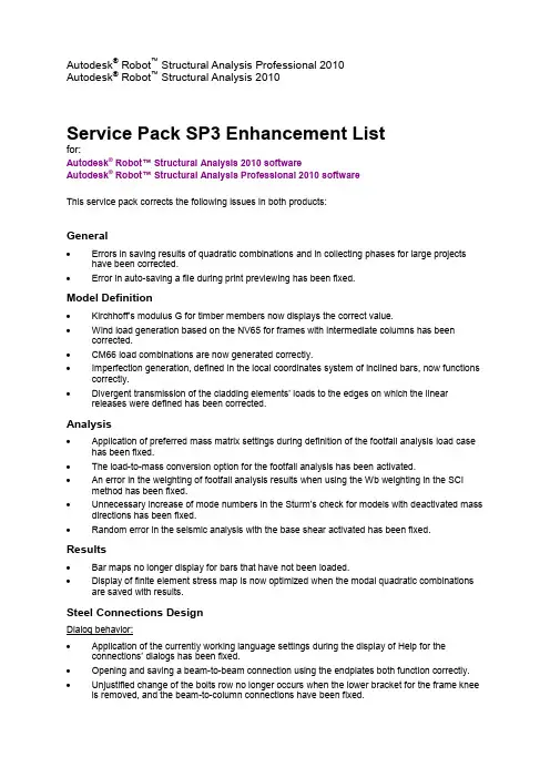
Autodesk® Robot™ Structural Analysis Professional 2010Autodesk® Robot™ Structural Analysis 2010Service Pack SP3 Enhancement Listfor:Autodesk® Robot™ Structural Analysis 2010 softwareAutodesk® Robot™ Structural Analysis Professional 2010 softwareThis service pack corrects the following issues in both products:General∙Errors in saving results of quadratic combinations and in collecting phases for large projects have been corrected.∙Error in auto-saving a file during print previewing has been fixed.Model Definition∙Kirchhoff’s modulu s G for timber members now displays the correct value.∙Wind load generation based on the NV65 for frames with intermediate columns has been corrected.∙CM66 load combinations are now generated correctly.∙Imperfection generation, defined in the local coordinates system of inclined bars, now functions correctly.∙Divergent transmission of the cladding elements’ loads to the edges on which the linear releases were defined has been corrected.Analysis∙Application of preferred mass matrix settings during definition of the footfall analysis load case has been fixed.∙The load-to-mass conversion option for the footfall analysis has been activated.∙An error in the weighting of footfall analysis results when using the Wb weighting in the SCI method has been fixed.∙Unnecessary increase of mode numbers in the Sturm’s check for models with deactivated mass directions has been fixed.∙Random error in the seismic analysis with the base shear activated has been fixed.Results∙Bar maps no longer display for bars that have not been loaded.∙Display of finite element stress map is now optimized when the modal quadratic combinations are saved with results.Steel Connections DesignDialog behavior:∙Application of the currently working language settings during the display of Help for the connections’ dialogs has been fixed.∙Opening and saving a beam-to-beam connection using the endplates both function correctly.∙Unjustified change of the bolts row no longer occurs when the lower bracket for the frame knee is removed, and the beam-to-column connections have been fixed.∙Recognition of a beam cut in a beam-to-beam connection has been fixed.∙The undefined “Beam length for calculations” data has been corrected.Connection definition:∙Problems with the import of tapered sections and their connection definitions have been fixed.∙Gusset plates are now generated correctly.∙Plates of sizes different from the beam-to-beam connection dialog data are now generated correctly.∙Fixed column base definition has been corrected.∙Stiffeners for the fixed column connections of columns made from hollow sections are now generated correctly.∙Distance between bolts in gussets and endplates is now recognized correctly.∙Excessive warnings about undefined stiffeners in the truss node connection are no longer generated.Connection verification:∙Calculation of the rotational stiffness S j,ini for beam-to-column and beam-to-beam connections has been fixed.∙EC3 beam-to-column connection with the endplate is now correctly checked.∙CM66 truss node connections are now correctly checked.∙Calculation of the effective width for the overlapping diagonal in truss tube connections has been fixed.∙Verification of the CM66 column base connections has been corrected.∙Stiffness calculation of the EC3 frame knee connection has been fixed.∙Endplate stiffness calculation of the EC3 beam-to-beam connection has been corrected.∙Efficiency ratio calculation for the truss connection using brackets has been corrected.Steel Members Design∙Information on the code check tab (always related to the first verified member) has been corrected.∙Consideration of moving loads in the calculations has been fixed.∙Wrong internal forces for the tension-only members in the nonlinear analysis have been corrected.∙Correct steel strength values are now used for the Australian standard AS4100 (steels 400P&F t=12-20 mm and 450P&F t=32-50 mm).∙The I sections in pure compression for small compression forces are now classified correctly for the EN 1993-1-1 standard calculation.∙Lack of the yield strength reduction for increasing element thickness based on the Danish annex to the EC3 has been corrected.∙The proper formula for bidirectional bending code check based on the EC3 is now used.∙Default structure type as sway for the calculation of buckling parameters based on the EC3 has been fixed.∙Manual changes of the material coefficients for calculations based on the EC3 are now properly considered.∙Selection controls in the Indian Standard calculation methods’ dialog box are now active.∙The lateral buckling C1 value based on the Spanish code SE-A:2006 is now calculated correctly. ∙The “c” coefficient for the SNIP code design is now calculated correctly.Timber Design∙Incorrect information on the code check tab (always related to the first verified member) has been corrected.Concrete Design∙Unnecessary display of “No error” no longer occurs when a project containing stirrups with pins is opened.∙Loss of information about the “cage method” based on the BAEL anchorage reinforcement pattern has been fixed.∙Calculation of beams with openings based on the BAEL code has been fixed.∙Change of results after the sequential calculations has been corrected.∙Collision of the top reinforcement bars in beams has been fixed.∙Selection of bars on the General tab of the reinforcement table now functions correctly.∙Wrong stamp sizes in the drawing tables have been corrected.∙Incorrect symbols of the closed stirrups have been fixed.∙Lack of information about the generated combinations based on ACI wall design has been fixed. ∙The value of the reduction strength factor based on ACI wall design is now correct.∙Unjustifiably large value of the required reinforcement based on the BAEL slabs has been fixed. ∙Very slow import from the Autodesk Robot software real reinforcement module has been corrected.Autodesk and Robot are registered trademarks or trademarks of Autodesk, Inc., and/or its subsidiaries and/or affiliates in the USA and/or other countries. All other brand names, product names, or trademarks belong to their respective holders. Autodesk reserves the right to alter product offerings and specifications at any time without notice, and is not responsible for typographical or graphical errors that may appear in this document.Occasionally, Autodesk makes statements regarding planned or future development efforts for our existing or new products and services. These statements are not intended to be a promise or guarantee of future delivery of products, services, or features but merely reflect our current plans, which may change. The Company assumes no obligation to update these forward-looking statements to reflect any change in circumstances,after the statements are made.© 2009 Autodesk, Inc. All rights reserved.。
【Robot中英对照说明书】(add ins)Preferences首选项【Robot中英对照说明书】(add ins)Preferences首选项Preferences首选项Topics in this section本节主题•Preferences•首选项•Languages•语音•General Parameters•一般参数•View Parameters•视图参数Use this dialog to select parameters for displaying graphics.•使用此对话框可以选择显示图形的参数。
•Desktop Settings•桌面设置•Toolbar and Menu•工具栏和菜单•Printout Parameters•打印输出参数•Advanced•高级•Calculations (Autodesk® Robot™ Structural Analysis 360)•计算(Autodesk®Robot™结构分析360)To access this dialog, click Tools > Preferences, and then select Calculations from the list of parameters.•要访问此对话框,请单击“工具”>“首选项”,然后从参数列表中选择“计算”。
•3D View - Work Modes•3D视图-工作模式Parent topic:Preliminary Setup父主题:初步设置Preferences首选项To access the Preferences dialog:要访问“首选项”对话框:•Click Tools menu > Preferences••单击“工具”菜单>“首选项”•Click (Preferences).••单击(首选项)。
After you click , a dialog displays that lets you select or modify the Robot parameters.单击后,将显示一个对话框,可用于选择或修改Robot参数。
一.新建一个项目打开REVIT后单击“新建项目”即可,默认情况下会使用REVIT自带的中国样板文件二.绘制轴网和标高轴网绘制方法:1. “常用”选项卡→“基准”面板→“轴网”1. 画出一条轴线1. 画第二条轴线,该案例中采用的是3900间距的轴网将鼠标放在轴网一端→向右移动,出现一条水平的虚线捕捉线→然后输入数据“3900”→回车键→画出第二条轴线1. 可以依照以上方法,画出所有轴线,如果像本实例一样,轴线之间尺寸都是相同的,也可以使用“阵列”命令选择一条画好的轴线→“修改轴网”选项卡→“阵列”→点选轴线→向右水平移动→输入间距“3900”→回车键→输入阵列数“10”→回车键1. 依照以上轴线画法,完成轴网,横向轴网的间距分别为8100,3600,8100轴网的常用设置:1. 更改轴网符号一般情况下轴网会按照阿拉伯数字一直排列下去,可以把横向的轴线改为用大写字母表示双击轴网旁的小球→输入大写字母“A”→回车键以后再画横向轴线时,便会从大写字母A开始排列1. 不显示轴网编号或者两头显示轴网编号点选一条轴线→单击轴网编号旁边的小方框→可切换是否显示轴网符号1. 修改轴网符号位置点选一条轴线→单击轴网编号附近的折断符号→拖拽小圆点,将轴网编号移动至合适的位置标高的绘制方法:标高在REVIT建模中有着非常重要的作用,REVIT建模中很多图元的定位都需要依靠标高来进行,因此建立一套精确详细的标高会使后面的建模过程方便很多。
标高绘制最好在轴网绘制之后进行,因为先画过轴网的话,绘制标高的时候会在立面图上显示轴网的位置,在绘制标高的时候能够有所参照。
1. 在左侧的REVIT项目浏览器中,打开“南立面”视图1. “常用”选项卡→“基准”面板→“标高”1. 将鼠标移动至标高线左侧端点,直至出现竖向虚线捕捉线,输入需要偏移于该标高线的高度,这里这条标高线为±0.000,输入偏移数量为“5400”,回车1. 向右移动鼠标,将标高线拉至需要的位置,这里我们拉至第六条轴网线的旁边1. 按照以上方法,画出剩余的标高线,结果如下轴网的绘制工作便完成了标高的相关设置:1. 改变标高名称,在标高比较多比较复杂的时候,需要建立完善的标高名称,以便以后建模过程的使用,本实例中建筑由两部分组成,两部分分别用L1和L2来表示。
autodesk inventor基础教程2021 -回复如何使用Autodesk Inventor 进行基本设计。
以下是基于2021 版本的教程。
第一步:安装和启动Autodesk Inventor1. 首先,从Autodesk 官方网站或合法的渠道下载并安装Autodesk Inventor 2021。
2. 完成安装后,打开Autodesk Inventor。
3. 在欢迎界面上,您可以选择新建一个项目或打开现有项目。
选择"新建" 以开始一个新项目。
第二步:创建一个新项目1. 在新项目对话框中,输入项目名称和所在位置等必要信息。
2. 确认文件单位和标准设置,按需选择英制或公制单位。
3. 在"启动设计" 标签下,选择适合您项目要求的模板。
通常,您可以选择"标准模型" 模板以开始设计。
4. 点击"创建" 按钮以创建新项目。
第三步:绘制草图1. 在"模型" 窗格中,选择"创建草图" 工具。
2. 在"绘制" 选项卡上,选择合适的草图平面。
您可以选择XY 平面、XZ 平面或YZ 平面等。
3. 使用绘图工具(如直线、圆弧、矩形等)开始绘制所需形状。
您还可以使用约束工具对草图进行对齐、距离和角度等约束。
4. 完成草图后,点击"结束草图" 以退出绘图环境。
第四步:创建特征1. 在"创建特征" 工具中,选择适当的特征(如挤压、旋转、孔等)。
2. 在图形预览窗口中选择草图或实体作为操作对象。
3. 输入参数和尺寸等相关信息,以确定特征的几何属性。
4. 点击"确定" 完成特征创建。
第五步:装配部件1. 在"装配" 窗格中,选择"创建装配" 工具。
2. 导入或创建所需的零部件作为装配的组成部分。
A u t o d e s k®R o b o t™S t r u c t u r a l A n a l y s i sP r o f e s s i o n a lV E R I F I C A T I O N M A N U A LF O R E C B E LG I A N N A D S T E E L C O D EMarch 2014© 2014 Autodesk, Inc. All Rights Reserved. Except as otherwise permitted by Autodesk, Inc., this publication, or parts thereof, may not be reproduced in any form, by any method, for any purpose.Certain materials included in this publication are reprinted with the permission of the copyrightholder.DisclaimerTHIS PUBLICATION AND THE INFORMATION CONTAINED HEREIN IS MADE AVAILABLEBY AUTODESK, INC. “AS IS.” AUTODESK, INC. DISCLAIMS ALL WARRANTIES, EITHEREXPRESS OR IMPLIED, INCLUDING BUT NOT LIMITED TO ANY IMPLIED WARRANTIESOF MERCHANTABILITY OR FITNESS FOR A PARTICULAR PURPOSE REGARDING THESEMATERIALS.TrademarksThe following are registered trademarks of Autodesk, Inc., in the USA and/or other countries:Autodesk Robot Structural Analysis Professional, Autodesk Concrete Building Structures, Spreadsheet Calculator, ATC, AutoCAD, Autodesk, Autodesk Inventor, Autodesk (logo), Buzzsaw,Design Web Format, DWF, ViewCube, SteeringWheels, and Autodesk Revit.All other brand names, product names or trademarks belong to their respective holders.Third Party Software Program CreditsACIS Copyright© 1989-2001 Spatial Corp. Portions Copyright© 2002 Autodesk, Inc.Copyright© 1997 Microsoft Corporation. All rights reserved.International CorrectSpell™ Spelling Correction System© 1995 by Lernout & Hauspie SpeechProducts, N.V. All rights reserved.Inst allShield™ 3.0. Copyright© 1997 InstallShield Software Corporation. All rights reserved.PANTONE® and other Pantone, Inc. trademarks are the property of Pantone, Inc.© Pantone, Inc.,2002.Portions Copyright© 1991-1996 Arthur D. Applegate. All rights reserved.Portions relating to JPEG © Copyright 1991-1998 Thomas G. Lane. All rights reserved. Portions ofthis software are based on the work of the Independent JPEG Group.Portions relating to TIFF © Copyright 1997-1998 Sam Leffler. © Copyright 1991-1997 SiliconGraphics, Inc. All rights reserved.Government UseUse, duplication, or disclosure by the U.S. Government is subject to restrictions as set forth inFAR 12.212 (Commercial Computer Software-Restricted Rights) and DFAR 227.7202 (Rights inTechnical Data and Computer Software), as applicable.I N T R O D U C T I O N (1)S T E E L (2)B E L G I U M E U R O C O D E3N B N E N1993-1:2005/A C:2009/A N B:2010 (3)G ENERAL R EMARKS (4)V ERIFICATION E XAMPLE -B ENDING WITH L ATERAL-TORSIONAL B UCKLING ANALYSIS FOR CANTILEVER (6)INTRODUCTIONThis verification manual contains numerical examples for structures prepared and originally calculated by Autodesk Robot Structural Analysis Professional version 2013. The comparison of results is still valid for the next versions.All examples have been taken from handbooks that include benchmark tests covering fundamental types of behaviour encountered in structural analysis. Benchmark results (signed as “Handbook”) are recalled, and compared with results of Autodesk Robot Structural Analysis Professional (signed further as “Robot”).Each example contains the following parts:- title of the problem- specification of the problem- Robot solution to the problem- outputs with calculation results and calculation notes- comparison between Robot results and exact solution- conclusions.S T E E LEurocode 3 (Belgian NAD) NBN EN 1993-1:2005/ AC:2009/ANB:2010Select preferences corresponding to your example using “Preferences…” or “Job Preferences…” (click Tools).A. PreferencesTo specify your regional settings in PREFERENCES dialog click Tools/ Preferences.Default PREFERENCES dialog opens e.g.:Select appropriate regional setting (e.g. Belgique) from the selection listB. Job PreferencesTo specify your job preferences in JOB PREFERENCES dialog click Tools/ Job Preferences.Default JOB PREFERENCES dialog opens, e.g.:You can define a new type of Job Preferences to make it easier in the future.First of all, make selection of documents and parameters appropriate for the project conditions from the list view tabs in JOB PREFERENCES dialog.For example, to choose code, click Design codes tab from the left list view; then select code from Steel/Aluminium structures selection list or press More codes button which opensConfiguration of Code List.Selection of an appropriate code category (e.g. Steel/Aluminum) from the combo boxopens a new suitable list. Set Belgian code as the current code.Press OK.After the job preferences decisions are set, you can save it under a new name (e.g. Belgian codes) by pressing Save Job Preferences iconin the JOB PREFERENCES dialog.1.2.TITLE:Critical moment Mcr for lateral torsional buckling of cantilever I-beam according to Belgian standard. SPECIFICATION:Calculate the values of critical moment Mcr for two I300 cantilever beams with a span of 3,0 m.The material is S235. Applied loads: uniform dead loads of pz = -10,0 kN/m acting on the top of beams. The weight of bars is negligible. The bars are unbraced.Verify:1. the first bar → without warping at the support end (fully fixed)2. the second one → with warping at the support endSOLUTION:After having defined and calculated the structure models, go to [Steel/Aluminum Design] tab.Define new types of members in accordance with the structure assumptions in DEFINITIONS dialog. It can be set in Member type combo box list.In this example, the beams (numbered 1 and 2) have to be defined as a cantilever for the purposesof a verification.(e.g. “beam”) may be initially opened.On Members tab, for the selected “Beam”from Member type combo box,press the Parameters button.It opens MEMBER DEFINITION - PARAMETERS dialog.Type a new name in Member type editable field. Next, change the parameters to meet the initial datarequirements of the structure. Set (as needed) the following lateral-buckling parameters: ∙switch on: the Lateral buckling check box or/and Flexural-torsional buckling check box Array∙define the appropriate Lateral buckling length coefficient fora member by pressing Upper/Lower flange. It opensLATERAL BUCKLING LENGTH COEFFICIENTS dialog.If a defined “Member type” is indicated as a cantilever the new option is activ ated in the form of the check box "Cantilever without warping effects".select the appropriate Load level icondefine the appropriate load type for a featured member by pressing [More…] button;It opens ADDITIONAL PARAMETERS dialognext, choose the load typeby pressing the icon - it opens Arraya new dialog∙select Method of calculation∙choose Additional sets of member parameters∙define bracings for Lateral buckling and B ucklingCan be done in two ways in [MEMBER DEFINITION-MEMBER] dialog:1st way - by pressing Upper/Lower flange button from Lateral buckling frame2nd way - by pressing either “Buckling length coeff.” icon from B uckling frameThe first method opensLATERAL BUCKLING LENGTH COEFFICIENTS dialog:The second one opensBUCKING TYPE DIAGRAMS dialog:For both methods if you click the last icon - Intermediate bracings - the new dialog INTERNAL BRACINGS will appear.In the INTERNAL BRACINGSdialog, there are possibilitiesto define bracings for bucklingand lateral bucklingfor a currently defined membertype independently.In this particular example no bracings were defined.Now, save the newly-created member types under new names.In the described example two member types were created:1. “fixed support” → prepared for el.1 without warping at the support end (fully fixed)2. “warping ends” →prepared for el.2 with warping at member’s ends.number of a member must beof Member type.→also any name of membercan be entered.In the CALCULATIONS dialog set the following:-> Verification options - list of v erified members,-> Loads cases - list of chosen loads-> Limit state-> ConfigurationBefore doing calculations you have to remember to specify appropriate parameters for verificationin the CONFIGURATION dialog. Access the CONFIGURATION dialog by clicking the [Configuration] button in the CALCULATIONS dialog.Now, start the calculations - press the Calculations button in CALCULATIONS dialog.MEMBER VERIFICATION dialog with the most significant messages (Messages tab) and results data (Results tab) will appear on screen.Pressing the line with results for the member 1 opens the RESULTS dialog with detailed resultsfor the analyzed member. The views of the RESULTS dialogs are presented below.Simplified results tabDetailed results tabPressing the [Calc.Note] button in “RESULTS - Code” dialog opens the printout note for the analyzed member. You can obtain Simplified results printout or Detailed results printout, depending on from which tab the choice was made. The printout note view of Simplified results is presented below.SIMPLIFIED RESULTS printout for member n o1STEEL DESIGN---------------------------------------------------------------------------------------------------------------------------------------- CODE: NBN EN 1993-1:2005/AC:2009/ANB:2010, Eurocode 3: Design of steel structures. ANALYSIS TYPE:Member Verification---------------------------------------------------------------------------------------------------------------------------------------- CODE GROUP:MEMBER: 1 without warping node1 POINT: 1 COORDINATE: x = 0.00 L = 0.00 m ---------------------------------------------------------------------------------------------------------------------------------------- LOADS:Governing Load Case: 1 DL1---------------------------------------------------------------------------------------------------------------------------------------- MATERIAL:S 235 ( S 235 ) fy = 235.00 MPa----------------------------------------------------------------------------------------------------------------------------------------SECTION PARAMETERS: IPE 300h=30.0 cm gM0=1.00 gM1=1.00b=15.0 cm Ay=36.16 cm2 Az=25.68 cm2 Ax=53.81 cm2tw=0.7 cm Iy=8356.11 cm4 Iz=603.78 cm4 Ix=19.47 cm4tf=1.1 cm Wely=557.07 cm3 Welz=80.50 cm3---------------------------------------------------------------------------------------------------------------------------------------- INTERNAL FORCES AND CAPACITIES:My,Ed = -45.00 kN*mMy,el,Rd = 130.91 kN*mMy,c,Rd = 130.91 kN*m Vz,Ed = 30.00 kNTau,z,max,Ed = 15.83 MPaMb,Rd = 120.19 kN*mClass of section = 3----------------------------------------------------------------------------------------------------------------------------------------LATERAL BUCKLING PARAMETERS:z = 1.00 Mcr = 305.38 kN*m Curve,LT - b XLT = 0.89Lcr,low=6.00 m Lam_LT = 0.65 fi,LT = 0.70 XLT,mod = 0.92---------------------------------------------------------------------------------------------------------------------------------------- BUCKLING PARAMETERS:About y axis: About z axis:---------------------------------------------------------------------------------------------------------------------------------------- VERIFICATION FORMULAS:Section strength check:My,Ed/My,c,Rd = 0.34 < 1.00 (6.2.5.(1))sqrt(Sig,x,Ed*^2 + 3*Tau,z,max,Ed^2)/(fy/gM0) = 0.34 < 1.00 (6.2.1.(5))Tau,z,max,Ed/(fy/(sqrt(3)*gM0)) = 0.12 < 1.00 (6.2.6.(4))Global stability check of member:My,Ed/Mb,Rd = 0.37 < 1.00 (6.3.2.1.(1))---------------------------------------------------------------------------------------------------------------------------------------- Section OKYou can also estimate the verifications for the other section or e.g. lighter IPE sectionin a convenient quick way:while still in R ESULTS-CODE dialog, type the required section name only in the combo box and choose the new section from a list, e.g. HEA 160.Press ENTER. Calculations and results for entered section are refreshed instantly.The results printout for the newly selected section can be presented by pressing [Calc.Note] button.COMPARISON of Critical Moment Mcr [kNm]for lateral-torsional buckling of a cantilever members:CONCLUSIONS:Belgium NBN EN 1993-1:2005/ AC:2009/ ANB:2010 standard provides formulas for calculating Mcr for a cantilever for two types of its support:1. without warping at the support end (fully fixed)2. with warping at the support end (fixed with warping).Agreement of Mcr results for:∙manually calculated & RSA - for all cases calculated according to Belgium standard;∙CTiCM LTBeam software & RSA (NBN code) – for a cantilever without warping at the support end (fully fixed).The differences between the results of calculations carried out according to Belgium standard and CTiCM LTBeam software appear for the case of beams with possiblitty of warping at both ends (these differences resulting from the use of other verification formulas in the above mentioned standards).。
Autodesk Robot 结构设计分析软件 标准入门手册 目录 Autodesk Robot 结构设计分析软件 快速浏览……………………………………………………………1 软件概述…………………………………………………………3
Robot模块…………………………………………………………3
Robot的页面布局………………………………………………5
软件的基本配置…………………………………………………6
首选项………………………………………………6 工程首选项……………………………………………7 导航功能………………………………………………8
Robot工作界面的使用方法………………………………10
系统菜单……………………………………10 文件菜单……………………………………11 编辑菜单……………………………………11 浏览菜单……………………………………12 图形菜单……………………………………12 荷载菜单……………………………………12 分析菜单……………………………………13 结果菜单……………………………………13 设计菜单………………………………13 工具菜单………………………………14 窗口菜单………………………………14 帮助菜单………………………………14 布置系统……………………………………………………15
输入结构分析数据……………………………………18
分析结构……………………………………………………22
结果预览……………………24 梁的示意图………………………………24 面的示意图………………………………26 彩图结果…………………………………………28 结构元素的设计……………………………………29
钢构件和木构件的设计…………………………29 钢连接设计………………………………32 RC设计…………………………………………34 所需钢筋面积(理论值)的计算……………………34 假设钢筋面积的计算…………35 报告及输出计算书…………………………37
快捷键列表……………………39
三维框架结构……………………………………41
软件配置…………………………………………43 模块定义………………………………………………44
杆的定义(二维框架)………………………………………44 约束的定义…………………………………………45 2D椼架的定义…………………………………………46 荷载定义………………………………47 特殊荷载工况下荷载的定义…………………………48 复制已有框架……………………………………52 横向梁的定义……………………………………53 交叉约束的定义………………………………54 复制已定义的杆(梁横截面或支撑)……………………56 结构分析………………………………………………57
结果预览……………………………………………………58
以图形的形式预览梁的结构………………………………58 以表格的形式预览杆的结构………………………………60 压力分析……………………………………………………61 打印前的准备…………………………………………64
“捕捉”视图和计算记录的数据……………………64 准备输出的计算书………………………………………65 打印输出计算报告……………………………………67 RC和钢混合结构…………………………………………71
程序的配置…………………………………………73 模型定义…………………………………………74
结构轴的定义…………………………………………74 截面的定义………………………………………………77 杆的定义………………………………………………80 约束的定义………………………………………………86 荷载工况的定义…………………………………………87 在预定义的荷载工况下定义荷载……………………89 改变结构类型……………………………………99 附加结构轴的定义…………………………………………99 复制已存在的框架…………………………………………101 横向梁的定义………………………… 103 板的定义……………………………………106 起始端的定义……………………………………109 墙面的定义…………………………………………114 墙面支撑的定义………………………………119 网格参数的定义……………………………………120 板荷载的定义………………………………124 结构分析……………………………………………………125
结果预览……………………………………………………128
以彩图形式显示面板…………………………128 结构的变形……………………………………131 以表格形式显示面板……………………133 Autodesk Robot Structural Analysis与Revit® Structure 的结合………………………139
将Revit模块导入到Robot中………………………………141
在Revit® Structure打开工程…………………………141 向Robot发送数据…………………………………142 Robot中的结构分析………………………………149
在屏幕上显示部件………………………………150 显示从Revit® Structure导入的荷载工况…………151 网格参数的定义…………………………………………153 计算………………………………………………156 结果预览——以彩图形式显示面板………………157 结果预览——以图表形式显示杆………………160 在Robot中结构的修正………………………………163
替换截面…………………………………………163 移除杆………………………………………………166 添加新元素…………………………………………167 从Robot中升级Revit模块………………………………172
升级Revit® Structure工程……………………172 显示模块变化……………………………………177 AUTODESK ROBOT 结构分析软件 快速浏览
摘要: 本手册的目的是为新手用户介绍Autodesk Robot结构分析系统,提供一些程序配置方面的指导,菜单系统和导航功能。还有许多数据输入和结果输出的方法。据了解,Autodesk Robot Structural Analysis 2011 可以在PC上成功安装。
软件概述 什么是Autodesk Robot 结构分析软件? Autodesk Robot 结构分析软件(Robot)用于建模分析以及各种结构分析的单一集成软件。 该软件允许用户创建结构、运行结构分析、检验获得的结果,执行规范以检查结构构件的计算,为已设计和计算的结构建立文档。 Robot – 下面是本商业版本软件的重要特征: *线性,非线性和动态(模态,频谱,地震,时间历史,推覆,P-delta,屈曲变形,塑性)结构分析。 *多语言工作环境(15种独立用户界面语言设置,设计及计算记录)。 *多国工作环境——根据50多个设计规范进行设计。 *框架、板和壳,加上一个功能强大的GUI建模工具和网格生成器允许,用户定义任何模拟形状的结构或配置 - 就像您分析真正的几何结构一样。 *与Revit®结构的双向集成的品质,再加上与国际金融组织及企业识别系统的整合。 *一个开放的应用程序编程接口,允许用户对自己的应用程序进行前/后期的处理。 Robot 模块 Robot 是一个拥有许多功能及普通用户工作环境的软件。 运行软件后,Robot弹出选择窗口,打开现存的结构或是输入已存的设计模块。 以下是出现的对话框: 1、选择已存的结构工程(选择工程): - 显示最近编辑过的工程 - 可选择存储在光盘上的工程 2、创建新工程(选择新工程) -显示默认结构类型(建筑设计,板设计,壳设计,3D框架设计)显示最近编辑过的工程。 -选择新建工程类型(更多选择)。 下面显示的窗口是选择新建工程后的截图。这个窗口用于选择将要分析的结构类型或是加载已存的结构。
图解2.1 Robot 模块窗口 注释:当光标移至窗口上的图标时,会显示其功能的简介。
以下是最常用的图标:
建筑设计 框架3D设计 壳设计(用于在3D结构下 椼架3D设计 为任何形状的表面建模)
板设计 框架2D设计 格架设计 椼架2D设计 目录 2.1 Robot 基本模块
Robot 的页面布局
图解 3.1 - Robot 经典页面布局 软件的基本配置