魔灯固件使用指南
- 格式:doc
- 大小:23.50 KB
- 文档页数:3
魔灯固件使用指南Audio:1. Audio Meters 音频测量器2. Analog Gain 声音插值模拟增益3. L-DigitalGain 左声道增益4. R-DigitalGain 右声道增益5. AGC ACG自动增益6. Input Source 声音输入源7. Mic Power 麦克风供电8. Output volume 输出音量9. Monitoring-USB USB端口监听LiveV1. Global Draw 全局信息显示2. Zebras 斑马纹曝光不足区域显示3. Focus Peak 对焦峰值4. Magic Zoom MW对焦同步放大器5. Cropmks(0/7) 剪裁比例6. Ghost Image 鬼影显示,要选定一张照片按LV键7. Live Defish8. Spotmeter 点测光9. False Color 伪色图,SET为开关,Q键选种类10. Histo/Wavefm 录像时显示直方图11. ClearScreen 清屏,半按快门时/待机时Expo:1. ISO 自定感光率2. WhiteBalance 自定色温,LV模式下按Q可以检测3. WBShift G/M 自定白平衡偏移4. WBShift B/A 自定白平衡偏移5. Shutter 自定快门速度,LV模式下按Q 检测6. Aperture 自定光圈7. Light Adjust 光线调节,高光色调优先/ALO浓度8. PictureStyle 照片风格9. REC PicStyle 录像的画面风格10. Contrast 对比度,LV模式下可实时查看11. Saturation 饱和度,LV模式下可实时查看12. Sharpness 清晰度13. Flash AEcomp 照片曝光补偿Movie:1. Bit Rate(CBR) 自定视频码率2. BuffWarnLevel 缓冲区报警设置3. Time Indicator 时间指示器4. Bitrate Info 比特率信息5. Movie Logging 生成短片文件日志6. Movie Restart 录像中断时(29分29秒)重新录像7. MovieModeRemap 视频模式映射8. REC/STBY notif 录制备用通知9. Movie REC key 录制热键设置10. Force LiveView 强制保持实时显示模式11. Force HDMI-VGA 强制同步输出HDIM或VGA信号Shoot:1. HDR Bracketing HDR档次,Q关闭/SET快门数/PLAY键设置EV值。
很多朋友见到这么多文件发给他,都是一头雾水,头蒙,该怎么升级,其实很简单,就是把固件复制到卡里,相机内升级固件就可以了。
相机出现绿色英文提示:please restart your camera,关机相机,再开机就好了。
删除键是魔灯的菜单,menu是佳能的菜单。
半按快门退出菜单。
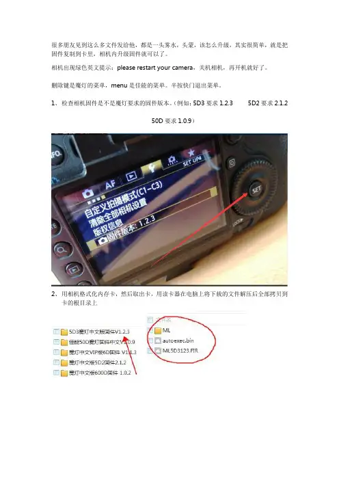
1、检查相机固件是不是魔灯要求的固件版本。
(例如:5D3要求1.2.3 5D2要求2.1.2
50D要求1.0.9)
2、用相机格式化内存卡,然后取出卡,用读卡器在电脑上将下载的文件解压后全部拷贝到
卡的根目录上
3、将卡插入相机,选择固件版本,按SET键,执行固件升级。
大约10秒,出现上图,立即关闭相机电源,必须在倒计时结束前关机相机电源。
打开相机,按删除键,调出ML菜单
5D3高级中文版,要告诉我你的机器码,格尼授权文件以后,才可以使用魔灯菜单
注意事项:相机不开机,按住SET键不松开开机(不加载魔灯固件)。
或者不装卡,重新插上电池就可以开机了,是因为卡里文件不对造成的。
实在开不开机,按住Q键和快门10秒后不松开,再开机!。

魔灯升级方法及使用指南魔灯升级方法及使用指南1. 简介魔灯是一款智能照明设备,具有多种灯光效果和智能控制功能。
本文档将详细介绍魔灯的升级方法以及使用指南。
2. 魔灯升级方法2.1 准备工作在升级魔灯之前,确保以下准备工作已完成:- 一台个人电脑或移动设备- USB数据线- 魔灯最新的固件升级程序2.2 固件升级程序访问魔灯官方网站,最新的固件升级程序到电脑或移动设备。
2.3 连接魔灯与电脑/移动设备使用USB数据线连接魔灯和电脑/移动设备。
2.4 启动固件升级程序运行的固件升级程序,并按照程序提示进行操作。
2.5 等待升级完成在固件升级过程中,不要断开魔灯与电脑/移动设备的连接,以免造成升级失败。
3. 魔灯使用指南3.1 魔灯启动按下魔灯上的电源按钮,即可启动魔灯。
3.2 灯光效果设置通过魔灯上的控制按钮或移动设备上的应用程序,可以切换不同的灯光效果。
例如,单色、渐变、跳变等。
3.3 亮度调节通过魔灯上的控制按钮或移动设备上的应用程序,可以调节魔灯的亮度。
3.4 定时功能魔灯具有定时功能,可以设置定时开关机,以满足不同场景下的需求。
3.5 远程控制通过移动设备上的应用程序,可以远程控制魔灯的开关、灯光效果、亮度等。
4. 附件本文档没有涉及到附件。
5. 法律名词及注释5.1 魔灯:指本文档涉及的智能照明设备。
5.2 固件:指魔灯的软件程序,包含了魔灯的功能和控制方法。
6. 结束语本文档提供了魔灯的升级方法及使用指南,希望能帮助用户更好地使用魔灯。
如需进一步了解或有任何疑问,请参考魔灯官方网站或联系客服。
魔灯固件使用指南魔灯固件使用指南Audio:1. Audio Meters 音频测量器2. Analog Gain 声音插值模拟增益3. L-DigitalGain 左声道增益4. R-DigitalGain 右声道增益5. AGC ACG自动增益6. Input Source 声音输入源7. Mic Power 麦克风供电8. Output volume 输出音量9. Monitoring-USB USB端口监听LiveV1. Global Draw 全局信息显示2. Zebras 斑马纹曝光不足区域显示3. Focus Peak 对焦峰值4. Magic Zoom MW对焦同步放大器5. Cropmks(0/7) 剪裁比例6. Ghost Image 鬼影显示,要选定一张照片按LV键7. Live Defish8. Spotmeter 点测光9. False Color 伪色图,SET为开关,Q键选种类10. Histo/Wavefm 录像时显示直方图11. ClearScreen 清屏,半按快门时/待机时Expo:1. ISO 自定感光率2. WhiteBalance 自定色温,LV模式下按Q可以检测3. WBShift G/M 自定白平衡偏移4. WBShift B/A 自定白平衡偏移5. Shutter 自定快门速度,LV模式下按Q检测6. Aperture 自定光圈7. Light Adjust 光线调节,高光色调优先/ALO浓度8. PictureStyle 照片风格9. REC PicStyle 录像的画面风格10. Contrast 对比度,LV模式下可实时查看11. Saturation 饱和度,LV模式下可实时查看12. Sharpness 清晰度13. Flash AEcomp 照片曝光补偿Movie:1. Bit Rate(CBR) 自定视频码率2. BuffWarnLevel 缓冲区报警设置3. Time Indicator 时间指示器4. Bitrate Info 比特率信息5. Movie Logging 生成短片文件日志6. Movie Restart 录像中断时(29分29秒)重新录像7. MovieModeRemap 视频模式映射8. REC/STBY notif 录制备用通知9. Movie REC key 录制热键设置10. Force LiveView 强制保持实时显示模式11. Force HDMI-VGA 强制同步输出HDIM或VGA信号Shoot:1. HDR Bracketing HDR档次,Q关闭/SET快门数/PLAY键设置EV值。
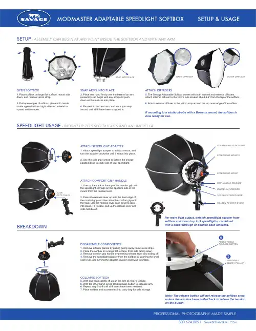
1. Place softbox on large flat surface, mount side down, and release velcro strap.2. Pull open edges of softbox, place both hands inside against left and right sides of material to spread softbox open.3. Place one hand firmly over the base of an arm (assembly can begin with any arm) and push down until arm clicks into place.4. Proceed to the next arm, and work your way around until all 8 have been snapped in.5. The Savage Adjustable Softbox comes with both internal and external diffusers. Attach internal diffuser to the velcro tabs located about 4.5” from the top of the softbox.6. Attach external diffuser to the velcro strip around the top outer edge of the softbox.If mounting to a studio strobe with a Bowens mount, the softbox is now ready for use.OPEN SOFTBOXSNAP ARMS INTO PLACEATTACH DIFFUSERSSNAP INTO PLACE INNER DIFFUSER SPEEDLIGHT MOUNTSADAPTER RELEASE LEVERSPEEDLIGHT MOUNTGRIP HANDLE RELEASE UMBRELLA RECEIVER TILT ADJUSTMENT KNOBTIGHTEN TO LIGHT STANDOUTER DIFFUSERSETUP- ASSEMBLY CAN BEGIN AT ANY POINT INSIDE THE SOFTBOX AND WITH ANY ARMSPEEDLIGHT USAGE- MOUNT UP TO 5 SPEEDLIGHTS AND AN UMBRELLAATTACH SPEEDLIGHT ADAPTERATTACH COMFORT GRIP HANDLEDISSASEMBLE COMPONENTSCOLLAPSE SOFTBOX1. Attach speedlight adapter to softbox mount, and turn the adapter clockwise until it snaps into place.2. Use the side grip screws to tighten the orange padded disks to each side of your speedlight.1. Line up the track at the top of the comfort grip with the speedlight carriage on the opposite side of the mount from the release lever.2. Press the release lever up with the front edge of the comfort grip and then slide the comfort grip onto the track until the release lever pops down to lock into place. To release, pull up the release lever and slide handle off.For more light output, detatch speedlight adapter from softbox and mount up to 5 speedlights, combinedwith a shoot through or bounce back umbrella.SLIDEONTO TRACK1. Remove diffuser panels by pulling gently away from velcro strips.2. Place the softbox on a large flat surface, front side facing down.3. Remove comfort grip handle by pressing release lever and sliding off.4. Remove the speedlight adapter from the softbox by pushing the small side lever, and turning the adapter counter clockwise to unlock.BREAKDOWNNote: The release button will not release the softbox arms unless the arm has been pulled back to relieve the tension on the button.145235. With one hand, gently lift up on the arm to relieve tension.6. With the other hand, press black release button to collapse arm.6. Repeat step 5 & 6 until all 8 arms have been released.7.Place softbox and accessories into carry bag for safe storage.GRIP ARM &5FIRMLY PRESS6a v age niversal com。
魔灯”定时曝光(延时拍摄)“使用指南
定时曝光又称延时拍摄,是利用延时自动控制器,按照预定的时间间距进行定格摄影的方法。
在影视中常常看到含苞待放的花朵,顷刻之间就吐艳盛开的情景,就是根据自然规律和镜头长度的需要,预先规定每拍摄一格的时间间距,用自动控制器,逐格地进行拍摄而成的。
下面请欣赏一下延时拍摄的魅力吧!
欣赏完以后具体介绍一下延时拍摄功能的使用说明:
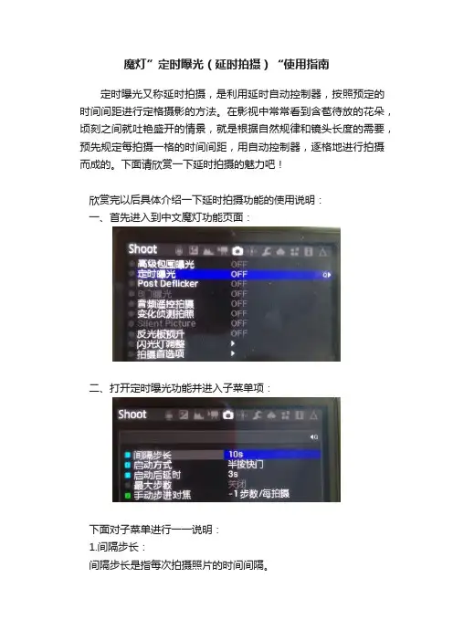
一、首先进入到中文魔灯功能页面:
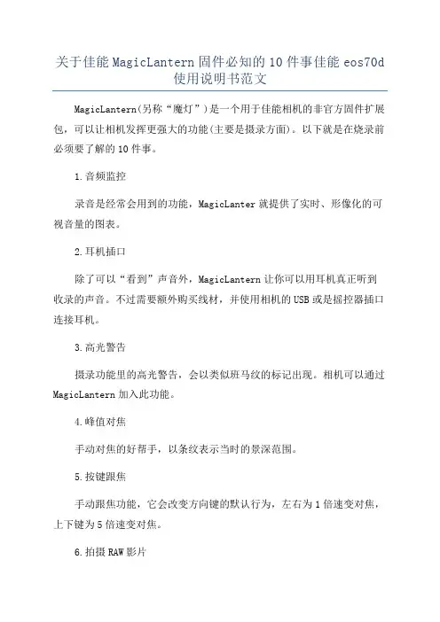
二、打开定时曝光功能并进入子菜单项:
下面对子菜单进行一一说明:
1.间隔步长:
间隔步长是指每次拍摄照片的时间间隔。
2.启动方式:
启动方式有三种,一是离开菜单,设定好以后离开菜单的时候即开始进行拍摄。
二是半按快门,设定好以后半按快门键即开始进行拍摄。
三是拍摄照片,设定好以后拍摄一张照片以后即开始进行拍摄。
3.启动后延时:
启动后延时是指,当你使用自己设定好的启动方式启动的时候,需要延时多长时间才开始进行拍摄。
4.最大步数:
最大步数是指此次延时拍摄时拍摄多少张自动停止,如果为0就会一直拍摄,需要手动停止,可直接关机停止或者按删除键进入菜单关闭。
5.手动步进对焦:
此设置必须要在自动对焦下才可使用(“AF”),可以选择加或者减步数/拍摄即每拍摄一张照片就会自动加或者减一次焦点位置。
很多朋友见到这么多文件发给他,都是一头雾水,头蒙,该怎么升级,其实很简单,就是把固件复制到卡里,相机内升级固件就可以了。
相机出现绿色英文提示:please restart your camera,关机相机,再开机就好了。
删除键是魔灯的菜单,menu是佳能的菜单。
半按快门退出菜单。
1、检查相机固件是不是魔灯要求的固件版本。
(例如:5D3要求1.2.3 5D2要求2.1.2
50D要求1.0.9)
2、用相机格式化内存卡,然后取出卡,用读卡器在电脑上将下载的文件解压后全部拷贝到
卡的根目录上
3、将卡插入相机,选择固件版本,按SET键,执行固件升级。
大约10秒,出现上图,立即关闭相机电源,必须在倒计时结束前关机相机电源。
打开相机,按删除键,调出ML菜单
5D3高级中文版,要告诉我你的机器码,格尼授权文件以后,才可以使用魔灯菜单
注意事项:相机不开机,按住SET键不松开开机(不加载魔灯固件)。
或者不装卡,重新插上电池就可以开机了,是因为卡里文件不对造成的。
实在开不开机,按住Q键和快门10秒后不松开,再开机!。

魔灯升级方法及使用指南魔灯是一种能够实现愿望的神奇道具,它在很多文学作品和故事中都被提及。
魔灯有许多版本和升级方式,下面将介绍一种常见的升级方法以及使用指南。
一、魔灯的升级方法1.1强化灯体材质在原有的基础上增加一层特殊材质,可以增加魔灯的耐用度和灯体强度。
可以选择一些高强度的金属材质,如铁、钢等,使灯体更加坚固耐用。
1.2增加灯中精灵数量由于魔灯中的精灵是实现愿望的关键,所以可以通过增加精灵的数量来提高魔灯的能力。
可以在原有的基础上增加一至两只精灵,也可以增加精灵的种类,如水灵、火灵等。
1.3提升精灵的能力精灵是魔灯的核心,提升精灵的能力也是一种升级方法。
可以通过培训、锻炼等方式来提升精灵的能力,使其更加强大和灵活。
1.4添加新的功能可以根据使用者的需求,给魔灯添加新的功能。
例如,可以为魔灯增加一个追踪功能,使魔灯能够根据使用者的意图自动追踪目标;或者可以增加一个时间暂停功能,使时间在特定区域内停滞。
二、魔灯的使用指南2.1准备工作在使用魔灯之前,需要对使用者自身进行一些准备工作。
首先,明确自己的愿望,并确定愿望的具体内容和要求。
其次,了解魔灯的规则和限制,避免因使用不当而导致后果不可预料。
2.2唤醒魔灯精灵当准备好后,可以开始使用魔灯。
首先,轻轻摩擦魔灯的表面,唤醒魔灯中的精灵。
在唤醒时要保持专注和诚意,不得有任何杂念或负面情绪。
2.3提出愿望当精灵出现后,可以向其提出愿望。
在提出愿望时,要清晰明确地表达自己的需求,并注意愿望的语言和措辞。
要避免模糊或含糊不清的表达,以免产生误解或产生不良后果。
2.4确认愿望在提出愿望后,精灵会确认愿望的内容和要求。
此时,使用者需要再次确认愿望的准确性和完整性,并与精灵达成共识。
2.5实现愿望一旦愿望得到确认,精灵会开始实现愿望。
在实现过程中,使用者需要保持耐心和信任,不得干涉或指导精灵的行动。
应相信精灵的能力和智慧,让其按照最佳的方式来实现愿望。
2.6接受结果当愿望实现后,使用者需要接受实现结果。
关于佳能MagicLantern固件必知的10件事佳能eos70d
使用说明书范文
MagicLantern(另称“魔灯”)是一个用于佳能相机的非官方固件扩展包,可以让相机发挥更强大的功能(主要是摄录方面)。
以下就是在烧录前必须要了解的10件事。
1.音频监控
录音是经常会用到的功能,MagicLanter就提供了实时、形像化的可视音量的图表。
2.耳机插口
除了可以“看到”声音外,MagicLantern让你可以用耳机真正听到收录的声音。
不过需要额外购买线材,并使用相机的USB或是摇控器插口连接耳机。
3.高光警告
摄录功能里的高光警告,会以类似班马纹的标记出现。
相机可以通过MagicLantern加入此功能。
4.峰值对焦
手动对焦的好帮手,以条纹表示当时的景深范围。
5.按键跟焦
手动跟焦功能,它会改变方向键的默认行为,左右为1倍速变对焦,上下键为5倍速变对焦。
6.拍摄RAW影片
通过升级此固件实现录制RAW影片功能。
7.双ISO
有点类似于自动感光度功能,可以让相机在两个感光度之间切换。
对于拍摄光比较大,或者需要转换场景的情况十分有用。
8.间隔拍摄(Intervalometer)
定时间隔拍摄功能,用来拍摄多重曝光或延时摄影很有用。
MagicLantern让你不用摇控器就可以做到。
9.免费
10.这些本是佳能应有的功能
这些功能都是由制作人从相机中发掘出来,换句话说,这其实都是佳能相机本来应该有的功能吧不过由于是非官方软件,所以MagicLantern 并不会针对烧录固件导致的相机问题进行担保。
BNI IOL-801-000-Z036 BNI IOL-802-000-Z036Smart Light User’s Guidey o f C M A /F l o d y n e /H y d r a d y n e ▪ M o t i o n C o n t r o l ▪ H y d r a u l i c ▪ P n e u m a t i c ▪ E l e c t r i c a l ▪ M e c h a n i c a l ▪ (800) 426-5480 ▪ w w w .cContent1Notes to the user 3 1.1 About this guide3 1.2 Structure of the guide3 1.3 Typographical conventions3 Enumerations 3 Actions 3 Syntax3 Cross-references3 1.4 Symbols3 1.5 Abbreviations3 2Safety4 2.1 Intended use4 2.2 General safety notes 4 2.3 Meaning of the warnings4 3Getting Started5 3.1 Overview BNI IOL-801-000-Z036 5 3.2 Overview BNI IOL-802-000-Z036 6 3.3 Mechanical connection7 3.4 Electrical connection 7 3.5 Function ground 7 3.6 IO-Link connection7 Sensor Hub connection 7 Module versions7 3.7 Short description of the functionality 8 3.8 Segment mode 8 3.9 Level mode 8 3.10 Runlight mode11 4IO-Link Interface 12 4.1 IO-Link Data12 4.2 Process data / Output data12 Bit definitions in segment mode13 4.3 Parameter data/ Request data16 Mode 40hex18 Number of segments 41hex 18 Level type 42hex18 Level resolution 43hex18 Level mode segment x color 44hex, 45hex, 46hex, 47hex, 48hex 18 Bit definition Segment x18 Level mode limit x-y, 49hex, 4Ahex, 4Bhex, 4Chex 19 Runlight mode, background color 4Dhex 20 Runlight mode, running color 4Ehex20 Runlight mode, number of running segments 4Fhex 20 Supply monitoring 50hex 21 Brightness 51hex21 Blinking frequency 52hex 22 Blinking mode 53hex22 4.4 Errors 22 4.5 Events22 5Technical Data 23 5.1 Dimensions23 5.2 Mechanical data 23 5.3 Electrical data23 5.4 Operating conditions 23 5.5 LED indicator24 Status LED24y o f C M A /F l o d y n e /H y d r a d y n e ▪ M o t i o n C o n t r o l ▪ H y d r a u l i c ▪ P n e u m a t i c ▪ E l e c t r i c a l ▪ M e c h a n i c a l ▪ (800) 426-5480 ▪ w w w .c6Appendix25 6.1 Product ordering code 25 6.2 Order information25 Included material25y o f C M A /F l o d y n e /H y d r a d y n e ▪ M o t i o n C o n t r o l ▪ H y d r a u l i c ▪ P n e u m a t i c ▪ E l e c t r i c a l ▪ M e c h a n i c a l ▪ (800) 426-5480 ▪ w w w .c1 Notes to the user1.1 About this guide This guide describes the Balluff BNI IOL-80x-000-Z03x for the application as status light module. Hereby it is about an IO-Link device which communicates by means of IO-Link protocol with the superordinate IO-Link master assembly.1.2 Structure of theguideThe guide is organized so that the sections build on one another. Section 2: Basic safety information.Section 3: The main steps for installing the device.Section 4: IO-Link, parameter and process data for the device. Section 5: Technical data for the device.1.3 Typographicalconventions The following typographical conventions are used in this Guide. Enumerations Enumerations are shown in list form with bullet points.• Entry 1, • Entry 2.ActionsAction instructions are indicated by a preceding triangle. The result of an action is indicated by an arrow.Ø Action instruction 1. Ä Action result. Ø Action instruction 2. SyntaxNumbers :Decimal numbers are shown without additional indicators (e.g. 123),Hexadecimal numbers are shown with the additional indicator hex (e.g. 00hex ).Cross-references Cross-references indicate where additional information on the topic can be found (seeSection 5 -"Technical Data“).1.4 SymbolsNote!This symbol indicates a security notice which most be observed.Note, tipThis symbol indicates general notes.1.5 AbbreviationsBNI DPP EMC FE IOL SPDUBalluff Networking Interface Direct Parameter PageElectromagnetic Compatibility Function Earth IO-LinkService Protocol Data Unity o f C M A /F l o d y n e /H y d r a d y n e ▪ M o t i o n C o n t r o l ▪ H y d r a u l i c ▪ P n e u m a t i c ▪ E l e c t r i c a l ▪ M e c h a n i c a l ▪ (800) 426-5480 ▪ w w w .c2 Safety2.1 Intended useThis guide describes the Balluff BNI IOL-80x-000-Z03x for the application as status light module. Hereby it is about an IO-Link device which communicates by means of IO-Link protocol with the superordinate IO-Link master assembly.2.2 General safetynotesInstallation and startupInstallation and startup are to be performed only by trained specialists. Any damage resulting from unauthorized manipulation or improper use voids the manufacturer's guarantee and warranty.The device complies with EMC Class A. Such equipment may generate RF noise. The operator must take precautionary measures accordingly.The device must be powered only using an approved power supply (see section 5 “Technical data”). Only approved cable may b e used.Operation and testingThe operator is responsible for observing local prevailing safety regulations. When defects and non-clearable faults in the device occur, take it out of service and secure against unauthorized use.Approved use is ensured only when the housing is fully installed.2.3 Meaning of thewarningsNote!The pictogram used with the word "Caution" warns of a possible hazardoussituation affecting the health of persons or equipment damage. Ignoring these warnings can result in injury or equipment damage.Ø Always observe the described measures for preventing this danger.y o f C M A /F l o d y n e /H y d r a d y n e ▪ M o t i o n C o n t r o l ▪ H y d r a u l i c ▪ P n e u m a t i c ▪ E l e c t r i c a l ▪ M e c h a n i c a l ▪ (800) 426-5480 ▪ w w w .c3 Getting Started3.1 Overview BNI IOL-801-000-Z036Fig. 3-1: BNI IOL-801-000-Z0361 Cap2 Segment 13 Segment 24 Segment 35 Socket6 M12 connector7 M18 thread for mounting 8 Status LED1234587 6y o f C M A /F l o d y n e /H y d r a d y n e ▪ M o t i o n C o n t r o l ▪ H y d r a u l i c ▪ P n e u m a t i c ▪ E l e c t r i c a l ▪ M e c h a n i c a l ▪ (800) 426-5480 ▪ w w w .c3 Getting Started3.2 Overview BNI IOL-802-000-Z036Fig. 3-2: BNI IOL-802-000-Z0361 Cap2 Segment 13 Segment 24 Segment 35 Segment 46 Segment 57 Socket8 M12 connector9 M18 thread for mounting10Status LED810679 54321y o f C M A /F l o d y n e /H y d r a d y n e ▪ M o t i o n C o n t r o l ▪ H y d r a u l i c ▪ P n e u m a t i c ▪ E l e c t r i c a l ▪ M e c h a n i c a l ▪ (800) 426-5480 ▪ w w w .c3 Getting Started3.3 Mechanicalconnection The BNI IOL-80x-000-Z03x modules are attached by using an M18 nut.3.4 Electricalconnection The BNI IOL-80x-000-Z03x modules require no separate supply voltage connection. Power is provided through the IO-Link interface by the host IO-Link Master.3.5 Function groundNote!The FE connection from the housing to the machine must be low-impedance and as short as possible.3.6 IO-LinkconnectionIO-Link (M12, A-coded, male)Sensor HubconnectionØ Connection protection ground to FE terminal, if present. ØConnect the incoming IO-Link line to the Sensor Hub.Note, tip!A standard 3 wire sensor cable is used for connecting to the host IO-Linkmaster.Module versionsFE terminal with a screw to connect protection groundy o f C M A /F l o d y n e /H y d r a d y n e ▪ M o t i o n C o n t r o l ▪ H y d r a u l i c ▪ P n e u m a t i c ▪ E l e c t r i c a l ▪ M e c h a n i c a l ▪ (800) 426-5480 ▪ w w w .c3 Getting Started3.7 Short description of the functionality The functionality of the Balluff status light module can be controlled through process dataand SPDU registers. It has three main mode of functionality: · Segment mode· Level mode · Runlight modeWith the help of these three modus various warning and indication signals can be indicated.3.8 Segment mode In the segment mode the module can be used as a standard status light, with configurablenumber of segments. Maximum five or three segments can be set, depending on the type of the Smartlight. The color of each segment can be selected form a color table, which has five pre-defined colors. To use the module as a standard status light, the Mode SPDU register must be set to segment mode. The number of the active segments must be set too. This can be done through number of segments SPDU register. Irrespectively of the selected number of segments, always all of the LEDs are used as a display element. The number of the segments can be set any number between 1 and the maximal number of the segments. The module has 20 or 12 LED (depending on the type of the Smartligth), which are equally distributed between the segments.(By BNI IOL-802-000-Z03x, when three segments are set, one-one LEDs between the segments will be always switched off).The process data controls the color of each segment. The combinations of the pre-defined colors are not limited. In the segment mode, the segments can be set to blink too. Each segment has a control bit in process data, which determines the blinking of thecorresponding segment. The blinking has two modus. Either normal blinking or flash mode can be selected. In normal blinking the LEDs are switched on and off periodically with a 50% duty cycle. In the flash mode, the LEDs are switched on and off quickly three times. The flash is repeated in every second. The type of the blinking can be set in SPDU register. The frequency of the normal blinking can be changed through an SPDU register.3.9 Level mode In level mode the complete module works as one indicator element. In this case a levelvalue can be displayed. The higher value the module becomes, the more LEDs will beswitched on. This mode can be used as a level indicator, for example to indicate a fluid level in a tank. To use the signal light as a level meter, the Mode SPDU register must be set to Level mode. In this case all of the LEDs are working as one display element. The number of the LEDs switched on depends on the input level. In the level mode the input process data does not give the colors of the segment, but the level. The resolution of the input level can be selected from 8 bit up to 16 bit.In the level mode various parameters can be controlled through SPDU registers. These parameters should be set before the level mode is used. The level display can be selected to be bottom-up or top-down. In the bottom-up mode the level indicator increases from the bottom of the module. In the top-down mode the indicator increases from the top of the module.Although there are no real segments in the level mode, because the LEDs are controlled by the input level, the LEDs are divided into five virtual segments. BNI IOL-801-000-Z03x module can be divided into 3 virtual segments, while the BNI IOL-802-000-Z03x can be divided into 5 virtual segments. These virtual segments can have their own color. The color of these segments can be set through SPDU register (Level mode segment x color SPDU register). So it can be realized, that the level meter can have more colors (up to themaximum number of the segments). Some or all colors can be set as dominant color. This means, when the input level is high enough to switch on the next LED and this LED is in another virtual segment, the LEDs, which are under the actual LED, take over the color of the actual LED. In this case, as the input level increases, the color of the full LED bar can be changed.The following examples are valid for BNI IOL-802-000-Z03x (Smartlight with 5 segments), the BNI IOL-801-000-Z03x (Smartlight with 3 segments) is working similar, only the number of the virtual segments are different. The lower two segments are green, the middle two segments are yellow color and the upper segment is red in the examples.y o f C M A /F l o d y n e /H y d r a d y n e ▪ M o t i o n C o n t r o l ▪ H y d r a u l i c ▪ P n e u m a t i c ▪ E l e c t r i c a l ▪ M e c h a n i c a l ▪ (800) 426-5480 ▪ w w w .c3 Getting StartedThe LED bar at increasing input data and no color dominance. (The virtual segments can be seen on the left side.) Of course the segment 2 or 4 does not have to be the same color as segment 3 or 5.y o f C M A /F l o d y n e /H y d r a d y n e ▪ M o t i o n C o n t r o l ▪ H y d r a u l i c ▪ P n e u m a t i c ▪ E l e c t r i c a l ▪ M e c h a n i c a l ▪ (800) 426-5480 ▪ w w w .c3 Getting StartedThe LED bar at increasing input data, all the colors are dominant.y o f C M A /F l o d y n e /H y d r a d y n e ▪ M o t i o n C o n t r o l ▪ H y d r a u l i c ▪ P n e u m a t i c ▪ E l e c t r i c a l ▪ M e c h a n i c a l ▪ (800) 426-5480 ▪ w w w .c3 Getting StartedBy default the 20 LED are divided into equal virtual segments. The height of the virtual segments can be modified too. There are four SPDU register (Level mode limit x-y SPDU register), in which the limits of the virtual segments can be modified. For example: If theinput level value is higher than the limit value of the 2. and 3. segment (level mode limit 2-3), the current LED will become the color of the Level mode segment 2 color.The LED bar at increasing input data, there is no color dominance. The Limits of thesegments are modified, so they are not equally distributed. Of course segment 3, 4 and 5 could have different colors too.3.10 Runlight modeIn the runlight mode, the complete module displays a running light effect. To use the module as a runlight display, the Mode SPDU register must be set to runlight mode. In this case all of the LEDs are working as one runlight effect. The process data has no meaning because the runlight mode is controlled only by SPDU registers.Four registers set the functionality of the runlight. The color of the running LEDs and the background color can be selected in two SPDU register. The colors are the same as the colors in the segment mode. The number of the running segments can be set too. In runlight mode 1, 2 or 3 running segments can be selected, but only by the 5 segment version. Smartlight with 3 segment can have only one running segment. One segment contains 4 LED. The speed of the running segment can be selected too. The blinking frequency register controls the speed of the running segment in runlight mode.y o f C M A /F l o d y n e /H y d r a d y n e ▪ M o t i o n C o n t r o l ▪ H y d r a u l i c ▪ P n e u m a t i c ▪ E l e c t r i c a l ▪ M e c h a n i c a l ▪ (800) 426-5480 ▪ w w w .c4 IO-Link Interface4.1 IO-Link Data4.2 Process data /Output dataBNI IOL-801-000-Z036, Segment Modey o f C M A /F l o d y n e /H y d r a d y n e ▪ M o t i o n C o n t r o l ▪ H y d r a u l i c ▪ P n e u m a t i c ▪ E l e c t r i c a l ▪ M e c h a n i c a l ▪ (800) 426-5480 ▪ w w w .c4IO-Link InterfaceBNI IOL-802-000-Z036, Segment ModeBit definitions in segment modeBit 0-2 / 4-6000 = off 001 = green 010 = red 011 = yellow 100 = blue 101 = reserved 110 = reserved 111 = whiteBit 3 / 70 – segment does not blink1 – segment blinks according to the blink modus settingsy o f C M A /F l o d y n e /H y d r a d y n e ▪ M o t i o n C o n t r o l ▪ H y d r a u l i c ▪ P n e u m a t i c ▪ E l e c t r i c a l ▪ M e c h a n i c a l ▪ (800) 426-5480 ▪ w w w .c4 IO-Link InterfaceBNI IOL-801-000-Z036, Level ModeLevel value: 8, 10, 12, 14 or 16 bit value for level indicator. The resolution can be set in Level resolution SPDU register. The Level value is always left justified.BNI IOL-802-000-Z036, Level ModeLevel value: 8, 10, 12, 14 or 16 bit value for level indicator. The resolution can be set in Level resolution SPDU register. The Level value is always left justified.y o f C M A /F l o d y n e /H y d r a d y n e ▪ M o t i o n C o n t r o l ▪ H y d r a u l i c ▪ P n e u m a t i c ▪ E l e c t r i c a l ▪ M e c h a n i c a l ▪ (800) 426-5480 ▪ w w w .c4 IO-Link InterfaceBNI IOL-801-000-Z036, Runlight ModeBNI IOL-802-000-Z036, Runlight ModeIn runlight mode the process data has no meanings, only SPDU registers are controlling the functionality.y o f C M A /F l o d y n e /H y d r a d y n e ▪ M o t i o n C o n t r o l ▪ H y d r a u l i c ▪ P n e u m a t i c ▪ E l e c t r i c a l ▪ M e c h a n i c a l ▪ (800) 426-5480 ▪ w w w .c4 IO-Link Interface4.3 Parameter data/Request datay o f C M A /F l o d y n e /H y d r a d y n e ▪ M o t i o n C o n t r o l ▪ H y d r a u l i c ▪ P n e u m a t i c ▪ E l e c t r i c a l ▪ M e c h a n i c a l ▪ (800) 426-5480 ▪ w w w .c4 IO-Link Interfacey o f C M A /F l o d y n e /H y d r a d y n e ▪ M o t i o n C o n t r o l ▪ H y d r a u l i c ▪ P n e u m a t i c ▪ E l e c t r i c a l ▪ M e c h a n i c a l ▪ (800) 426-5480 ▪ w w w .c4 IO-Link InterfaceMode 40hexThe operating mode of the module.0 = Segment mode 1 = Level mode 2 = Runlight modeNumber ofsegments 41hexNumber of the segments.Note, tip!When BNI IOL-802-000-Z036 is configured to have 3 segments, 1-1 LED is always switched of between the segments.Level type 42hexThe type of the level indicator.0 = bottom up 1 = top downLevel resolution 43hexThe resolution of the input data in level mode.0 = 8 bit 1 = 10 bit 2 = 12 bit 3 = 14 bit 4 = 16 bitLevel modesegment x color 44hex, 45hex,46hex, 47hex, 48hexBit definition Segment xBit 0-2, color of the x segment000 = off 001 = green 010 = red 011 = yellow 100 = blue 101 = reserved 110 = reserved 111 = whiteBit 3, color dominance0 - color is not dominant 1 - color is dominanty o f C M A /F l o d y n e /H y d r a d y n e ▪ M o t i o n C o n t r o l ▪ H y d r a u l i c ▪ P n e u m a t i c ▪ E l e c t r i c a l ▪ M e c h a n i c a l ▪ (800) 426-5480 ▪ w w w .c4 IO-Link InterfaceLevel mode limit x-y,49hex, 4A hex, 4B hex , 4C hexAn 8, 10, 12, 14, 16 bit number (depends on the resolution) determines the limits between two segments in level mode. The limit values are always right justified.y o f C M A /F l o d y n e /H y d r a d y n e ▪ M o t i o n C o n t r o l ▪ H y d r a u l i c ▪ P n e u m a t i c ▪ E l e c t r i c a l ▪ M e c h a n i c a l ▪ (800) 426-5480 ▪ w w w .c4 IO-Link InterfaceRunlight mode, background color 4D hexThe color of the background in runlight modeBit 0-2, background color000 = off 001 = green 010 = red 011 = yellow 100 = blue 101 = reserved 110 = reserved 111 = whiteRunlight mode, running color 4E hexThe color of the running segment in runlight modeBit 0-2, running color000 = off 001 = green 010 = red 011 = yellow 100 = blue 101 = reserved 110 = reserved 111 = whiteRunlight mode, number of running segments 4F hexNumber of the running segments. Each segment contains 4 LED. Values between 1 and 3 can be sety o f C M A /F l o d y n e /H y d r a d y n e ▪ M o t i o n C o n t r o l ▪ H y d r a u l i c ▪ P n e u m a t i c ▪ E l e c t r i c a l ▪ M e c h a n i c a l ▪ (800) 426-5480 ▪ w w w .c4IO-Link InterfaceSupply monitoring 50hexUnder voltage Us 0: Us voltage is Ok1: Low voltage on IO-Link pin 1LED Voltage failure 0: LED Voltage is Ok 1: LED Voltage failureBrightness 51hex At three byte SPDU register sets the brightness for each channel (red, green, blue). Values from 0x00 to 0x7F are accepted.y o f C M A /F l o d y n e /H y d r a d y n e ▪ M o t i o n C o n t r o l ▪ H y d r a u l i c ▪ P n e u m a t i c ▪ E l e c t r i c a l ▪ M e c h a n i c a l ▪ (800) 426-5480 ▪ w w w .c4 IO-Link InterfaceBlinking frequency 52hex The frequency of the blinking can be selected. It is only valid for 50% duty cycle blinking. The frequency of the flashing cannot be changed. Values between 1 and 5 are accepted. One means the slowest and five means the fastest blinking.Note, tip!The blinking frequency register affects not only blinking frequency, but the speed of the running light.Blinking mode 53hexSegment x flashing bit sets the mode of the blinking.0 - blinking with 50% duty cycle 1 - flashingNote!Through this register only the mode of the blinking can be set (either 50% duty cycle or flash). The blinking of the desired segment must be activated in process data to enable blinking.4.4 Errors4.5 Eventsy o f C M A /F l o d y n e /H y d r a d y n e ▪ M o t i o n C o n t r o l ▪ H y d r a u l i c ▪ P n e u m a t i c ▪ E l e c t r i c a l ▪ M e c h a n i c a l ▪ (800) 426-5480 ▪ w w w .c5 Technical Data5.1 DimensionsBNI IOL-802-000-Z036BNI IOL-801-000-Z0365.2 Mechanical data5.3 Electrical data5.4 Operatingconditionsy o f C M A /F l o d y n e /H y d r a d y n e ▪ M o t i o n C o n t r o l ▪ H y d r a u l i c ▪ P n e u m a t i c ▪ E l e c t r i c a l ▪ M e c h a n i c a l ▪ (800) 426-5480 ▪ w w w .c5 Technical Data5.5 LED indicatorStatus LEDThe status LED indicates the current status of the power supply and the communication. It can be switched on, switched of and flashing.LED is flashingLED is flashingStatus LEDy o f C M A /F l o d y n e /H y d r a d y n e ▪ M o t i o n C o n t r o l ▪ H y d r a u l i c ▪ P n e u m a t i c ▪ E l e c t r i c a l ▪ M e c h a n i c a l ▪ (800) 426-5480 ▪ w w w .c6 Appendix6.1 Product orderingcode6.2 Order informationIncluded material BNI IOL-80x-000-Z036 consists of the following components:· signal light · M18x1 nut · rubber foot · screw M4 · spring washer · user’s guideBNI IOL-80x-000-Z036Balluff Networking Interface IO-Link Interface801: Smart Light 3 Segment 802: Smart Light 5 SegmentStandard versionMechanical designZ036 = Die-cast zinc housing, matte nickel plated Polycarbonate transparent housing Bus connection M12 external thread, Module fastening M18 external thready o f C M A /F l o d y n e /H y d r a d y n e ▪ M o t i o n C o n t r o l ▪ H y d r a u l i c ▪ P n e u m a t i c ▪ E l e c t r i c a l ▪ M e c h a n i c a l ▪ (800) 426-5480 ▪ w w w .cNotesy o f C M A /F l o d y n e /H y d r a d y n e ▪ M o t i o n C o n t r o l ▪ H y d r a u l i c ▪ P n e u m a t i c ▪ E l e c t r i c a l ▪ M e c h a n i c a l ▪ (800) 426-5480 ▪ w w w .cBalluff GmbH516 E · E d i t i o n 1306 · R e v i s e d E d i t i o n 1304 · S u b j e c t t o m o d i f i c a t i o ny o f C M A /F l o d y n e /H y d r a d y n e ▪ M o t i o n C o n t r o l ▪ H y d r a u l i c ▪ P n e u m a t i c ▪ E l e c t r i c a l ▪ M e c h a n i c a l ▪ (800) 426-5480 ▪ w w w .c。

魔灯升级方法及使用指南(一)引言概述:魔灯是一款独特的智能照明设备,通过简单的操作可实现多种灯光效果和控制方式。
本文将为您提供魔灯的升级方法及使用指南,以帮助您充分利用这一智能照明设备的功能。
正文:一、升级方法1. 确认设备型号:在进行升级之前,首先需要确认您的魔灯设备型号,以确保下载正确的升级包。
2. 下载升级包:访问魔灯官方网站或应用商店,下载适用于您的设备型号的最新升级包。
3. 连接设备与电脑:使用USB数据线将设备连接至电脑,并确保电脑上已安装设备驱动程序。
4. 导入升级包:将下载的升级包导入到魔灯设备的根目录或指定升级文件夹中。
5. 执行升级:断开设备与电脑的连接,重新启动魔灯设备,按照设备界面的指引执行升级操作。
二、使用指南1. 灯光模式切换:利用魔灯设备上的开关按钮或通过手机App 进行灯光模式的切换。
2. 亮度调节:根据需要,通过设备上的亮度调节按钮或手机App进行灯光的亮度调节。
3. 色温调节:魔灯可实现冷、暖光色温的调节,通过设备上的色温调节按钮或手机App进行调节。
4. 定时功能设置:利用设备的定时功能,可按照设置的时间自动开启或关闭魔灯,提供更便捷的使用体验。
5. 联动控制:通过将魔灯与其他智能设备连接,如音乐播放器、智能助手等,实现联动控制,打造更丰富的照明效果。
总结:本文介绍了魔灯的升级方法及使用指南。
通过升级可获得更好的设备性能和功能体验。
使用指南部分详细介绍了魔灯的灯光模式切换、亮度调节、色温调节、定时功能设置和联动控制等功能,帮助用户更好地利用魔灯的智能照明功能,满足不同场景的需求。
希望本文对您在使用魔灯过程中能起到一定的指导作用。
1.请确保您的600D官方固体版本为1.0.2 ;2.将相机设置全部清除,回到初始状态;3.将拔盘转至“M”档;4.刷机前确保电池有80%以上的电量;5.魔灯V2.3没有为600D开启音频控制功能。
刷机有风险,请慎重!特别提醒:经本人亲身体验,使用ML的实时取景模式(如:峰值对焦、魔术放大、斑马纹等在实时取景下才能发挥效用)会很消耗电量。
各菜单选项说明一.Expo 曝光1. WhiteBalance 白平衡2. ISO自定ISO感光度3. Shutter 快门4. Aperture 光圈5. PictureStyle 照片风格设定6. REC PicStyle 录影风格设定7. Exp.Override 曝光优先二.Overlay 显示模式1. Global Draw 球形绘制2. Zebras 条纹显示3. Focus Peak 对焦辅助4. Magic Zoom 放大镜(魔术放大)5. Cropmarks 照片裁切构图辅助6. Ghost image 重影显示(要选定一张照片按LV键)7. Defishing 专供三洋8mm鱼眼矫正8. Spotmeter 点测光9. False color 伪色图10. Histogram 录影显示直方图(柱状图)Waveform 录影显示直方图(波形)11. Vectorscope 向量范围图三.Movie 影片1.Bit Rate 自定视频码率2.Time Indicator时间指示器3.Movie Logging影片记录4.Movie Restart 影片重新启动设定5.REC/STBY notif录制或待机自定义通知6.Movie REC key录影热键设置7.Force LiveView录制保持开启显示模式8.Shutter Lock 快门锁定9. FPS override 帧数优先10.HDR video 高动态范围视频11.Image Effects 图像效果四.Shoot 快门1.HDR Bracketing HDR包围2.Intervalometer 延时摄影3.Bulb/Focus Ramping B门曝光/焦距修正4.Bulb Timer 慢速快门5.Motion Detect 移动侦测快门6.Silent Picture 在LV模式下半按快门.自动静音拍摄7.Mirror Lockup 反光镜锁定8.Flash tweaks 闪光灯调整...五.Focus 对焦1.Trap Focus 陷阱对焦2.Focus Patterns 对焦方式3.Follow Focus 跟踪对焦4.Focus Step Size 焦距步长5.Focus Step Delay 对焦延迟6.Focus End Point 对焦结束点7.Rack Delay 聚焦延迟8.Rack Focus变焦9.Stack focus 焦点叠加10.Focus distance and DOF info 焦距和DOF信息六.Display 萤幕显示1.LV contrast LV对比2.LV saturation LV饱和3.LV display gain LV显示增益4.Color scheme 颜色方案5.Clear overlays 清除复盖6. Focus box (LV) 对焦框(LV)7.Force HDMI-VGA8.Screen layout settings 屏幕布局设置9.Audio Meters音频指示器七.Prefs 偏好设置1.Image review settings 图片查看设置2.LiveView zoom settings 实时查看缩放设置3.Arrow/SET shortcuts 箭头/ SET键的快捷方式设置4.Misc key settings 其它键设置5.Powersave in LiveView 实时查看时省电模式设置6. Config file…配置文件7.LV display presets LV显示预设8.Crop Factor Display 裁切系数显示八.Debug调试1.Screenshot – 10s 截图–10秒后2.Don’t click me! 这一项请不要按,否则会花屏!需关机再开才能消除3.Stability tests 稳定性试验4.Show tasks…显示任务…5.Save CPU usage log 保存CPU使用记录6. Free Memory 可用内存7.Shutter Count 快门次数(供参考,不是很准确,我这里后面的2168就不知道是什么意思,实际已使用快门7286次)8.CMOS Temperat CMOS温度九.最后一项是帮助信息, 不做介绍,省略……Magic Lantern 菜单详解按删除按钮显示菜单,使用箭头键导航。
【图】中文魔灯固件使用“峰值对焦”使用指南官方合作邮箱:******************峰值对焦是在使用手动镜头或手动对焦模式时,透过观察被摄物体是否显现峰值色彩来判断是否成功对焦。
峰值对焦中的峰值颜色随着调焦,在取景画面中连续可见,取景框中任何位置都可以是对焦点,操作者可以在相机的显示屏里随意调整合焦平面的分布,可以随意决定合焦的主体。
下面就具体说明如何进行设置:一、如果是自动镜头请将镜头推到MF档位,手动镜头无需设置。
二、在liveview模式下,按“info”键将相机调整到魔灯取景模式,如下图1所示:三、打开魔灯功能页面,选择“峰值对焦”,按“Q”键进入子菜单,如下图2、图3所示:四、下面对子菜单进行一一说明:1、过滤器偏离:过滤器偏离有三个选项,增强边缘是指对被拍摄物体边缘的敏感度进行增强,细节是对被拍摄物体本身细节的敏感度进行增强,平衡兼顾了以上两方面的敏感度,如下图4所示。
2、图像缓冲区:图像缓冲区有两种选择高分辨率和低分辨率,如果光线较暗的情况下选择低分辨率可提高识别度,否则选择高分辨率。
3、门槛:门槛是指手动调焦过程中拍摄物体所占像素是总像素多少的时候就被认定为焦点。
从 0.1%~1.0%是以 0.1%递增,从 1%~5.0%是以 0.5%递增。
拍摄简单光滑的物体时数要调小,反之拍摄复杂物体时门槛值要调大,如下图5所示。
4、颜色:颜色选项是指表现峰值的颜色,这里说明一下“全局聚焦”和“本地聚焦”,选择全局聚焦的效果是在整个被拍摄物体上显示上面的几种颜色的某一种颜色,本地聚焦是在拍摄物体上出现以上几种颜色的混合颜色,如下图6所示。
5、灰度图像:当打开灰度图像功能时,实时显示呈现的是黑白图像,但是拍摄出来的结果是彩色的,当被拍摄物体是五颜六色的时候,峰值颜色不好分辨的时候,就要开启此功能来分辨。
图1。
魔灯Dual ISO(双感光度)的理解与设置探索(原创)作者愚翁移山(landagent)1.什么是Dual ISO(双感光度)?Dual ISO(双感光度)就是两个ISO值同时在一张照片上感光呈现图像。
高ISO H和低ISO l是隔双行间隔排列成像的,即在光学传感器CMOS上的分布如下:l l l l l l l l l lH H H H H H H H H HH H H H H H H H H Hl l l l l l l l l ll l l l l l l l l lH H H H H H H H H HH H H H H H H H H Hl l l l l l l l l ll l l l l l l l l l...........在解析图像的时候(通过中文魔灯卡导出工具或cr2hdr解析),高光部分ISO H高光溢出,去除不要,用ISO l插值填补;同样,在暗区,ISO l低位截止,也摒弃,用ISO H插值填补;在中间值部分,ISO H降低亮度与ISO l混合成像。
2.为什么要用Dual ISO?当我们看到蓝天白云,美丽景色的时候,多想拍一张蓝天白云清晰可见,山水花木又历历在目。
但是,往往事与愿违,把蓝天白云拍摄清楚了(曝光准确了),山水就变暗了;反之,山水拍摄清楚了,天空就过曝了,失去了云彩的轮廓。
这是什么原因呢?是相机的宽容度不够。
Dual ISO是直接提高相机CMOS的感光宽容度,在双感光度下成像,提高低光区域亮度,减少噪声,保留高光区域细节,不至于高光溢出。
3.什么时候用Dual ISO?当场景亮区与暗区光比超过12EV时,即超出了相机的动态范围,就可以使用Dual ISO (双感光度)。
什么是EV?曝光值(Exposure Value):是由快门速度值和光圈值组合表示摄影镜头通光能力的一个数值。
曝光值每改变1EV,将改变一挡曝光,即改变曝光时间或光圈一档。
相机的动态范围多少?以佳能EOS 6D为例:ISO 100 动态范围11.4EVISO 200 动态范围11.4EVISO 400 动态范围11.2EVISO 800 动态范围10.9EVISO 1600 动态范围10.4EV也就是说佳能EOS 6D的动态范围不超过12EV,所以我们说超过12EV时,就可以使用Dual ISO(双感光度)。
Magic Lantern v2.3 - User's Guide魔术灯2.3版用户指南资料来源:http://wiki.magiclantern.fm/userguide内容下载时间:2014年2月中文翻译:蜗居客Features产品特点●Audio: disable AGC, audio meters, manual audio controls, selectable input source (internal,internal+external, external stereo, balanced), audio monitoring via A/V cable.音频:使用自动增益控制、音频表、手动音频控制、可选择的输入源(内部,内部+外部,外部立体声,平衡状态)、通过A / V电缆监控音频。
●Exposure helpers: ETTR, zebras, false color, histogram, waveform, spotmeter, vectorscope.曝光辅助:向右曝光、斑马图、伪彩色、直方图、波形图、点测光表、矢量图。
●Focus tools: focus peaking, zoom while recording, trap focus, rack_focus, follow_focus,stack_focus.对焦工具:峰值对焦、录像中变焦、陷阱对焦、焦点偏移、跟踪对焦。
●Movie helpers: Bitrate control, movie logging (Exif-like metadata), auto-restart after bufferoverflow or 4 GB limit, HDR video, advanced FPS control.摄像辅助:比特率控制、录像记录(EXIF类型的元数据)、缓冲区溢出或因4 GB的限制中断后自动重新启动录像过程、高动态视频、高级每秒帧数控制。
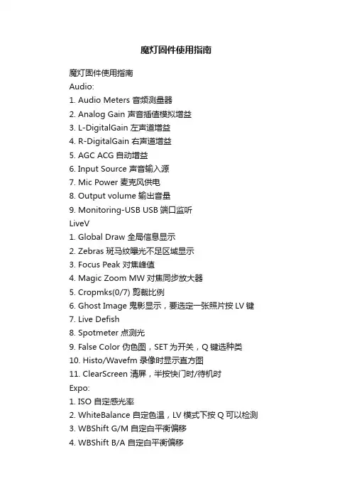
魔灯固件使用指南Audio:
1. Audio Meters 音频测量器
2. Analog Gain 声音插值模拟增益
3. L-DigitalGain 左声道增益
4. R-DigitalGain 右声道增益
5. AGC ACG自动增益
6. Input Source 声音输入源
7. Mic Power 麦克风供电
8. Output volume 输出音量
9. Monitoring-USB USB端口监听
LiveV
1. Global Draw 全局信息显示
2. Zebras 斑马纹曝光不足区域显示
3. Focus Peak 对焦峰值
4. Magic Zoom MW对焦同步放大器
5. Cropmks(0/7) 剪裁比例
6. Ghost Image 鬼影显示,要选定一张照片按LV键
7. Live Defish
8. Spotmeter 点测光
9. False Color 伪色图,SET为开关,Q键选种类
10. Histo/Wavefm 录像时显示直方图
11. ClearScreen 清屏,半按快门时/待机时
Expo:
1. ISO 自定感光率
2. WhiteBalance 自定色温,LV模式下按Q可以检测
3. WBShift G/M 自定白平衡偏移
4. WBShift B/A 自定白平衡偏移
5. Shutter 自定快门速度,LV模式下按Q检测
6. Aperture 自定光圈
7. Light Adjust 光线调节,高光色调优先/ALO浓度
8. PictureStyle 照片风格
9. REC PicStyle 录像的画面风格
10. Contrast 对比度,LV模式下可实时查看
11. Saturation 饱和度,LV模式下可实时查看
12. Sharpness 清晰度
13. Flash AEcomp 照片曝光补偿
Movie:
1. Bit Rate(CBR) 自定视频码率
2. BuffWarnLevel 缓冲区报警设置
3. Time Indicator 时间指示器
4. Bitrate Info 比特率信息
5. Movie Logging 生成短片文件日志
6. Movie Restart 录像中断时(29分29秒)重新录像
7. MovieModeRemap 视频模式映射
8. REC/STBY notif 录制备用通知
9. Movie REC key 录制热键设置
10. Force LiveView 强制保持实时显示模式
11. Force HDMI-VGA 强制同步输出HDIM或VGA信号
Shoot:
1. HDR Bracketing HDR档次,Q关闭/SET快门数/PLAY键设置EV值。
2. Take a pic ever 设定间隔拍摄时间,第三项需激活
3. Intervalometer 间隔拍摄启动,PLAY或MENU件停止
4. Bulb Ramping 曝光斜坡图
5. Bulb Timer 自定义慢速快门
6. LCD Remote Shot 使用LCD感应器拍照
7. Audio RemoteShot 使用话筒感知声音拍照
8. Motion Detect 运动、移位侦测拍照
9. Silent/slit pic 无声图片/分割图片,文件扩展名422
10. Mirror Lockup 反光板锁定,LV模式按第二次快门反光板即可复位
Focus:
1. Trap Focus 陷阱对焦,MF档,半按快门对焦完成即拍照
2. Focus Patterns 集中对焦
3. Follow Focus 按键跟焦
4. Focus StepSize 焦点选择
5. Focus StepDelay 对焦延迟
6. Focus End Point 对焦后自动结束
7. Rack focus 虚焦,LV模式下MF档调焦距
8. Stack focus 对焦堆积,SET调节,PLAY运行,LV模式下
Tweaks:
1. LVGain(NightVision) 添加LV模式
2. Exposure Simulation 模拟曝光
3. DOF Preview 景深预览
4. AF frame display AF帧显示
5. LCD Sensor Shortcuts 手动调整LCD亮度,挡住感应器按上下键
6. Auto BurstPicQuality 自动图片分割质量
7. Show cropmarks in 显示剪裁比例
8. ISO selection ISO选择
9. LV Auto ISO (M mode) LV模式自动ISO
10. Crop Factor Display 系数显示
11. LiveView Zoom LV时放大比例,PLAY键选择
Play:
1. SET+MainDial(play)
2. Cropmarks
3. After taking a pic 已使用的照片
4. Zoom in PLAY mode 缩放模式
5. Quick Erase 快速删除
Config:
1. Config AutoSave 参数自动保存
2. Save config now 保存参数
3. Delete config file 删除设置文件
4. DISP profiles 设置文件地址设置Debug:此功能调试相机用,非特殊情况严禁使用!
Power:电源
1. Dim display 显示较暗时
2. Turn off LCD and LV 关闭LCD和LV模式时
3. Turn off GlobalDraw
4. Save power when REC 当录制时保存电源信息Help:帮助文件。